EP1972786A2 - Rotary compressor, car air conditioner and water heater including the compressor - Google Patents
Rotary compressor, car air conditioner and water heater including the compressor Download PDFInfo
- Publication number
- EP1972786A2 EP1972786A2 EP08011548A EP08011548A EP1972786A2 EP 1972786 A2 EP1972786 A2 EP 1972786A2 EP 08011548 A EP08011548 A EP 08011548A EP 08011548 A EP08011548 A EP 08011548A EP 1972786 A2 EP1972786 A2 EP 1972786A2
- Authority
- EP
- European Patent Office
- Prior art keywords
- compression element
- airtight container
- refrigerant
- pressure
- cylinder
- Prior art date
- Legal status (The legal status is an assumption and is not a legal conclusion. Google has not performed a legal analysis and makes no representation as to the accuracy of the status listed.)
- Granted
Links
Images


Classifications
-
- F—MECHANICAL ENGINEERING; LIGHTING; HEATING; WEAPONS; BLASTING
- F04—POSITIVE - DISPLACEMENT MACHINES FOR LIQUIDS; PUMPS FOR LIQUIDS OR ELASTIC FLUIDS
- F04C—ROTARY-PISTON, OR OSCILLATING-PISTON, POSITIVE-DISPLACEMENT MACHINES FOR LIQUIDS; ROTARY-PISTON, OR OSCILLATING-PISTON, POSITIVE-DISPLACEMENT PUMPS
- F04C18/00—Rotary-piston pumps specially adapted for elastic fluids
- F04C18/30—Rotary-piston pumps specially adapted for elastic fluids having the characteristics covered by two or more of groups F04C18/02, F04C18/08, F04C18/22, F04C18/24, F04C18/48, or having the characteristics covered by one of these groups together with some other type of movement between co-operating members
- F04C18/34—Rotary-piston pumps specially adapted for elastic fluids having the characteristics covered by two or more of groups F04C18/02, F04C18/08, F04C18/22, F04C18/24, F04C18/48, or having the characteristics covered by one of these groups together with some other type of movement between co-operating members having the movement defined in group F04C18/08 or F04C18/22 and relative reciprocation between the co-operating members
- F04C18/356—Rotary-piston pumps specially adapted for elastic fluids having the characteristics covered by two or more of groups F04C18/02, F04C18/08, F04C18/22, F04C18/24, F04C18/48, or having the characteristics covered by one of these groups together with some other type of movement between co-operating members having the movement defined in group F04C18/08 or F04C18/22 and relative reciprocation between the co-operating members with vanes reciprocating with respect to the outer member
- F04C18/3562—Rotary-piston pumps specially adapted for elastic fluids having the characteristics covered by two or more of groups F04C18/02, F04C18/08, F04C18/22, F04C18/24, F04C18/48, or having the characteristics covered by one of these groups together with some other type of movement between co-operating members having the movement defined in group F04C18/08 or F04C18/22 and relative reciprocation between the co-operating members with vanes reciprocating with respect to the outer member the inner and outer member being in contact along one line or continuous surfaces substantially parallel to the axis of rotation
- F04C18/3564—Rotary-piston pumps specially adapted for elastic fluids having the characteristics covered by two or more of groups F04C18/02, F04C18/08, F04C18/22, F04C18/24, F04C18/48, or having the characteristics covered by one of these groups together with some other type of movement between co-operating members having the movement defined in group F04C18/08 or F04C18/22 and relative reciprocation between the co-operating members with vanes reciprocating with respect to the outer member the inner and outer member being in contact along one line or continuous surfaces substantially parallel to the axis of rotation the surfaces of the inner and outer member, forming the working space, being surfaces of revolution
-
- F—MECHANICAL ENGINEERING; LIGHTING; HEATING; WEAPONS; BLASTING
- F04—POSITIVE - DISPLACEMENT MACHINES FOR LIQUIDS; PUMPS FOR LIQUIDS OR ELASTIC FLUIDS
- F04C—ROTARY-PISTON, OR OSCILLATING-PISTON, POSITIVE-DISPLACEMENT MACHINES FOR LIQUIDS; ROTARY-PISTON, OR OSCILLATING-PISTON, POSITIVE-DISPLACEMENT PUMPS
- F04C23/00—Combinations of two or more pumps, each being of rotary-piston or oscillating-piston type, specially adapted for elastic fluids; Pumping installations specially adapted for elastic fluids; Multi-stage pumps specially adapted for elastic fluids
- F04C23/001—Combinations of two or more pumps, each being of rotary-piston or oscillating-piston type, specially adapted for elastic fluids; Pumping installations specially adapted for elastic fluids; Multi-stage pumps specially adapted for elastic fluids of similar working principle
-
- F—MECHANICAL ENGINEERING; LIGHTING; HEATING; WEAPONS; BLASTING
- F04—POSITIVE - DISPLACEMENT MACHINES FOR LIQUIDS; PUMPS FOR LIQUIDS OR ELASTIC FLUIDS
- F04C—ROTARY-PISTON, OR OSCILLATING-PISTON, POSITIVE-DISPLACEMENT MACHINES FOR LIQUIDS; ROTARY-PISTON, OR OSCILLATING-PISTON, POSITIVE-DISPLACEMENT PUMPS
- F04C23/00—Combinations of two or more pumps, each being of rotary-piston or oscillating-piston type, specially adapted for elastic fluids; Pumping installations specially adapted for elastic fluids; Multi-stage pumps specially adapted for elastic fluids
- F04C23/008—Hermetic pumps
-
- F—MECHANICAL ENGINEERING; LIGHTING; HEATING; WEAPONS; BLASTING
- F04—POSITIVE - DISPLACEMENT MACHINES FOR LIQUIDS; PUMPS FOR LIQUIDS OR ELASTIC FLUIDS
- F04C—ROTARY-PISTON, OR OSCILLATING-PISTON, POSITIVE-DISPLACEMENT MACHINES FOR LIQUIDS; ROTARY-PISTON, OR OSCILLATING-PISTON, POSITIVE-DISPLACEMENT PUMPS
- F04C2210/00—Fluid
- F04C2210/10—Fluid working
- F04C2210/1027—CO2
-
- F—MECHANICAL ENGINEERING; LIGHTING; HEATING; WEAPONS; BLASTING
- F04—POSITIVE - DISPLACEMENT MACHINES FOR LIQUIDS; PUMPS FOR LIQUIDS OR ELASTIC FLUIDS
- F04C—ROTARY-PISTON, OR OSCILLATING-PISTON, POSITIVE-DISPLACEMENT MACHINES FOR LIQUIDS; ROTARY-PISTON, OR OSCILLATING-PISTON, POSITIVE-DISPLACEMENT PUMPS
- F04C2210/00—Fluid
- F04C2210/10—Fluid working
- F04C2210/1072—Oxygen (O2)
-
- F—MECHANICAL ENGINEERING; LIGHTING; HEATING; WEAPONS; BLASTING
- F25—REFRIGERATION OR COOLING; COMBINED HEATING AND REFRIGERATION SYSTEMS; HEAT PUMP SYSTEMS; MANUFACTURE OR STORAGE OF ICE; LIQUEFACTION SOLIDIFICATION OF GASES
- F25B—REFRIGERATION MACHINES, PLANTS OR SYSTEMS; COMBINED HEATING AND REFRIGERATION SYSTEMS; HEAT PUMP SYSTEMS
- F25B2400/00—General features or devices for refrigeration machines, plants or systems, combined heating and refrigeration systems or heat-pump systems, i.e. not limited to a particular subgroup of F25B
- F25B2400/02—Centrifugal separation of gas, liquid or oil
-
- Y—GENERAL TAGGING OF NEW TECHNOLOGICAL DEVELOPMENTS; GENERAL TAGGING OF CROSS-SECTIONAL TECHNOLOGIES SPANNING OVER SEVERAL SECTIONS OF THE IPC; TECHNICAL SUBJECTS COVERED BY FORMER USPC CROSS-REFERENCE ART COLLECTIONS [XRACs] AND DIGESTS
- Y10—TECHNICAL SUBJECTS COVERED BY FORMER USPC
- Y10S—TECHNICAL SUBJECTS COVERED BY FORMER USPC CROSS-REFERENCE ART COLLECTIONS [XRACs] AND DIGESTS
- Y10S418/00—Rotary expansible chamber devices
- Y10S418/01—Non-working fluid separation
Definitions
- the electromotive element 14 is disposed above the upper cover 66 in the airtight container 12 at a predetermined interval.
- a peripheral portion of the upper cover 66 is fixed to the upper support member 54 from above via main bolts 78... Tips of the main bolts 78... engage with the lower support member 56.
- a refrigerant introducing tube 92 for introducing the refrigerant gas into the upper cylinder 38 is inserted/connected into the sleeve 141, and one end of the refrigerant introducing tube 92 communicates with a suction passage (not shown) of the upper cylinder 38.
- the refrigerant introducing tube 92 passes through an upper part of the airtight container 12 to reach the sleeve 144, and the other end thereof is inserted/connected into the sleeve 144 to communicate with the inside of the airtight container 12.
- the lower end of the space portion 102 has a substantially conical shape gradually thinned toward the fine hole 108, and the lower end of the fine hole 108 opens toward the oil reservoir 13 formed in the bottom part of the airtight container 12.
- the oil separation mechanism 100 is disposed in the airtight container 12 of the rotary compressor 10, the refrigerant circuit including the compressor 10 can be prevented from being enlarged, and this can contribute to miniaturization of an apparatus.
- a refrigerant introducing tube 294 for introducing the refrigerant gas into the lower cylinder 240 is inserted/connected into the sleeve 342, and one end of the refrigerant introducing tube 294 communicates with the suction passage 258 of the cylinder 240.
- upper and lower support members 425, 445 which are support members for blocking an upper opening surface of the upper cylinder 421 and a lower opening surface of the lower cylinder 441 and for serving also as bearings of the rotation shaft 404.
- a discharge valve 430 of the second stage compression element 420 for opening/closing the discharge port 429 is disposed in an upper part of the upper support member 425 in a state in which the valve is positioned in the discharge noise silencing chamber 427.
- the lower cover 448 is constituted of a donut-shaped circular steel plate, and fixed to the lower support member 445 from below by main bolts 465 in a peripheral portion thereof. It is to be noted that tips of the main bolts 465 engage with the upper support member 425.
- a low-pressure (LP) refrigerant drawn in the compression chamber 441a of the lower cylinder 441 on the low pressure chamber side is compressed by the operation of the lower roller 443 and the lower vane 444 to obtain an intermediate pressure (MP), and discharged into the discharge noise silencing chamber 447 formed in the lower support member 445 from the lower cylinder 441 on the high pressure chamber side via the discharge port 449.
- MP intermediate pressure
- the gas refrigerant having the intermediate pressure discharged into the discharge noise silencing chamber 447 is discharged into the airtight container 402 from the intermediate discharge tube 466 via a communication path (not shown), and accordingly the inside of the airtight container 402 obtains the intermediate pressure.
- the discharged refrigerant in the second stage compression element 420 is circulated in a refrigerant circuit (not shown) disposed outside the two-stage compression system rotary compressor 401 from the discharge noise silencing chamber 427 formed in the upper support member 425 via the discharge piping 432, and drawn in a first stage compression element 440 side again.
- the rotary compression mechanism section 510 is constituted of a high stage side compression element 520 and a low stage side compression element 540 which are driven by the rotation shaft 504 of the electric motor 503.
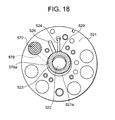
- the high stage side compression element 520 and the low stage side compression element 540 are constituted of: an intermediate partition plate 560; upper and lower cylinders 521, 541 disposed on/under the intermediate partition plate 560; upper and lower eccentric portions 522, 542 disposed on the rotation shaft 504 with a phase difference of 180 degrees in the upper and lower cylinders 521, 541; upper and lower rollers 523, 543 (see FIGS. 17 , 18 ) fitted into the upper and lower eccentric portions 522, 542 to eccentrically rotate; upper and lower vanes 524, 544 (see FIGS.
- suction passages 526a, 546a which connect suction ports 526, 546 (see FIGS. 17 , 18 ) to the insides of the upper and lower cylinders 521, 541, respectively, and dented discharge noise silencing chambers 527, 547.
- the discharge noise silencing chambers 527, 547 communicate with discharge ports 529, 549. Openings of these discharge noise silencing chambers 527, 547 are closed by covers, respectively. That is, the discharge noise silencing chamber 527 is closed by an upper cover 528, and the discharge noise silencing chamber 547 is closed by a lower cover 548.
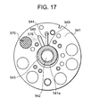
- the refrigerant in a refrigerant circuit connected to the outside is drawn in a compression chamber 541a of the lower cylinder 541 on the low pressure chamber side via the suction piping 551, and the suction passage 546a formed in the lower support member 545 and further via a suction port 546 shown in a lower surface view of the lower cylinder 541 in FIG. 17 .
Abstract
Description
- The present invention relates to a rotary compressor constituted by housing a driving element and a rotary compression mechanism section driven by the driving element in an airtight container, and a car air conditioner and a heat pump type water heater using the rotary compressor.
- This type of rotary compressor has heretofore been, for example, an internal intermediate pressure type multistage (two-stage) compression system rotary compressor including first and second rotary compression elements, and the compressor is constituted of a driving element and a rotary compression mechanism section driven by the driving element in an airtight container.
- Moreover, a refrigerant gas is drawn in a cylinder on the side of a low pressure chamber via a suction port of the first rotary compression element, compressed by an operation of a roller and a vane to obtain an intermediate pressure, and discharged into the airtight container from the side of a high pressure chamber of the cylinder via a discharge port and a discharge noise silencing chamber. Moreover, the refrigerant gas having the intermediate pressure in the airtight container is drawn in the cylinder on the side of the low pressure chamber from a suction port of the second rotary compression element, compressed by the operation of the roller and vane in a second stage to constitute a high-temperature/pressure refrigerant gas, and discharged to the outside of the compressor from the side of the high pressure chamber via the discharge port and discharge noise silencing chamber.
- Moreover, a bottom portion in the airtight container is constituted as an oil reservoir, and oil is pumped up from the oil reservoir by an oil pump (oil supply means) attached to one end (lower end) of a rotation shaft, and supplied to a sliding portion of the rotary compression mechanism section to lubricate and seal the portion (see, for example, Japanese Patent No.
2507047 2-294587 2000-105004 2000-105005 2003-74997 10-141270 - However, the oil mixed in the refrigerant gas compressed by the first rotary compression element as described above is discharged into the airtight container, and separated from the refrigerant gas to a certain degree in the process of movement in a space in the airtight container. However, the oil mixed in the refrigerant gas compressed by the second rotary compression element is discharged as such to the outside of the compressor together with the refrigerant gas.
- Therefore, there has been a problem that the oil in the oil reservoir runs short and that a sliding performance or sealing property lowers. There has also been a possibility that a trouble is caused in refrigerant circulation in a refrigerant circuit, or the refrigerant circuit is adversely affected otherwise by the oil discharged to the outside of the compressor.
- Moreover, an oil separator is connected to a piping outside the airtight container to separate the oil from the discharged refrigerant gas, and the oil is devised to be returned to the compressor in this manner, but there has been a problem that an installation space enlarges.
- According to the present invention, there is provided a vertical rotary compressor constituted by housing a driving element and a rotary compression mechanism section driven by the driving element in an airtight container, the compressor comprising: oil separation means, disposed in the airtight container, for centrifugally separating oil in a refrigerant which has been compressed by the rotary compression mechanism section and discharged.
- Moreover, according to the present invention, in the above-described invention, the oil separation means is disposed in the vicinity of the rotary compression mechanism section in a space between the airtight container and the rotary compression mechanism section.
- Furthermore, according to the present invention, there is provided a rotary compressor constituted by comprising a driving element and a rotary compression element driven by the driving element in an airtight container, the compressor comprising: a cylinder constituting the rotary compression element; a support member which blocks an opening surface of the cylinder; a discharge noise silencing chamber formed in the support member to communicate with the inside of the cylinder; and a cover attached to the support member to block an opening of the discharge noise silencing chamber on a side opposite to the cylinder, wherein a discharge passage for discharging a refrigerant discharged into the discharge noise silencing chamber from the cylinder to the outside of the airtight container is formed in the cover.
- Additionally, in the rotary compressor of the present invention, additionally, a cover side discharge noise silencing space which communicates with the discharge noise silencing chamber is formed in the cover.
- Moreover, in the rotary compressor of the present invention, additionally, the discharge passage is connected to the discharge noise silencing chamber in a state in which the discharge passage is partitioned from the cover side discharge noise silencing space.
- Furthermore, according to the present invention, there is provided a rotary compressor comprising: a rotary compression mechanism section constituted of first and second stage compression elements in such a manner that a discharged gas from the first stage compression element is drawn in the second stage compression element; an electric motor which drives the rotary compression mechanism section; an airtight container in which the electric motor and the rotary compression mechanism section are housed and which is filled with a discharged gas refrigerant of the first stage compression element; an oil reservoir portion formed in a bottom part of the airtight container; and an oil supply passage including one end opened in a space portion which is an oil passage formed in an outer periphery of a rotation shaft of the electric motor, and the other end opened in an in-cylinder space portion formed between a compression step end point and a suction step start point in a cylinder wall of the second stage compression element.
- Additionally, according to the present invention, there is provided a rotary compressor comprising: a rotary compression mechanism section constituted of a low stage side compression element and a high stage side compression element in such a manner that a discharged gas from the low stage side compression element is drawn in the high stage side compression element; an electric motor which drives the rotary compression mechanism section; an airtight container in which the electric motor and the rotary compression mechanism section are housed and which is filled with a discharged gas refrigerant of the low stage side compression element; and a pressure control valve housed in a housing constituting the rotary compression mechanism section, wherein the pressure control valve is constituted to introduce the gas refrigerant in the airtight container into a cylinder of the high stage side compression element, when a discharge pressure of the low stage side compression element lowers to a predetermined value or less and to interrupt the introducing of the gas refrigerant in the airtight container into the cylinder, when the discharge pressure of the low stage side compression element exceeds the predetermined value and rises.
- Moreover, the pressure control valve comprises: a piston; and a cylinder in which the piston is slidably housed. Furthermore, a resultant force of a low pressure side pressure and an elastic force of a spring, and a gas refrigerant pressure in the airtight container are applied in a facing manner to the piston, the piston is moved in one direction in the cylinder by the resultant force in such a manner as to be capable of introducing the gas refrigerant in the airtight container into the cylinder of the high stage side compression element, when the discharge pressure of the low stage side compression element lowers to the predetermined value or less, and the piston is moved in the other direction by the gas refrigerant pressure in the airtight container against the resultant force to interrupt the introducing of the gas refrigerant in the airtight container into the cylinder, when the discharge pressure of the low stage side compression element exceeds the predetermined value and rises.
- Furthermore, according to the present invention, there is provided a car air conditioner comprising: the above-described rotary compressor, wherein a carbon dioxide gas is used as a refrigerant.
- Additionally, according to the present invention, there is provided a heat pump type water heater comprising: the above-described rotary compressor, wherein a carbon dioxide gas is used as a refrigerant.
-
-
FIG. 1 is a vertical sectional view of a vertical rotary compressor according to one embodiment of the present invention; -
FIG. 2 is a diagram showing a flow of a refrigerant gas in an oil separation mechanism of the rotary compressor ofFIG. 1 ; -
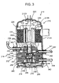
FIG. 3 is a vertical side view of an internal intermediate pressure type multistage (two-stage) compression system rotary compressor including first and second rotary compression elements as an embodiment of another rotary compressor of the present invention; -
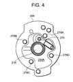
FIG. 4 is a plan view of an upper support member constituting the rotary compressor ofFIG. 3 ; -
FIG. 5 is a vertical side view of the rotary compressor according to another embodiment of the present invention; -
FIG. 6 is a vertical side view of the rotary compressor according to still another embodiment of the present invention; -
FIG. 7 is a plan view of the upper support member constituting the rotary compressor according to still another embodiment of the present invention; -
FIG. 8 is a vertical sectional view of a two-stage compression system rotary compressor according to still another embodiment of the present invention; -
FIG. 9 is a lower surface view of a lower support member of the two-stage compression system rotary compressor ofFIG. 8 ; -
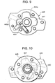
FIG. 10 is an upper surface view of the upper support member and an upper cover of the two-stage compression system rotary compressor ofFIG. 8 ; -
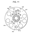
FIG. 11 is a lower surface view of a lower cylinder of the two-stage compression system rotary compressor ofFIG. 8 ; -
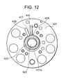
FIG. 12 is an upper surface view of an upper cylinder of the two-stage compression system rotary compressor ofFIG. 8 ; -
FIG. 13 is a schematically enlarged view around an opening of an oil supply passage in the upper cylinder of the two-stage compression system rotary compressor ofFIG. 8 ; -
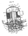
FIG. 14 is a vertical sectional view of the two-stage compression system rotary compressor according to still another embodiment of the present invention; -
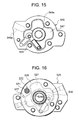
FIG. 15 is a lower surface view of the lower support member of the two-stage compression system rotary compressor ofFIG. 14 ; -
FIG. 16 is an upper surface view of the upper support member and upper cover of the two-stage compression system rotary compressor ofFIG. 14 ; -
FIG. 17 is a lower surface view of the lower cylinder of the two-stage compression system rotary compressor ofFIG. 14 ; -
FIG. 18 is an upper surface view of the upper cylinder of the two-stage compression system rotary compressor ofFIG. 14 ; -
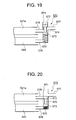
FIG. 19 is a schematic structure diagram of a pressure control valve in the two-stage compression system rotary compressor ofFIG. 14 , showing a state in which an intermediate pressure is lower than a predetermined value: -
FIG. 20 is a schematic structure diagram of the pressure control valve in the two-stage compression system rotary compressor ofFIG. 14 , showing a state in which the intermediate pressure exceeds the predetermined value: -
FIG. 21 is an explanatory view of an intermediate pressure control by the pressure control valve of the two-stage compression system rotary compressor ofFIG. 14 ; and -
FIG. 22 is a general characteristic graph showing a relation between an outside air temperature and a high/low/intermediate pressure in a case where the two-stage compression system rotary compressor ofFIG. 14 is applied to a heat pump type water heater. -
FIG. 1 shows a vertical rotary compressor of one embodiment of the present invention, and shows a vertical sectional view of arotary compressor 10 of an internal intermediate pressure type multistage (two-stage) compression system, including first and secondrotary compression elements - In
FIG. 1 ,reference numeral 10 denotes a vertical rotary compressor of the internal intermediate pressure type multistage compression system. Therotary compressor 10 is constituted of: a vertical andcylindrical airtight container 12 formed of a steel plate; anelectromotive element 14 which is a driving element disposed/housed above an inner space of theairtight container 12; and a rotarycompression mechanism section 18 disposed under theelectromotive element 14 and constituted of a first rotary compression element 32 (first stage) and a second rotary compression element 34 (second stage) driven by arotation shaft 16 of theelectromotive element 14. - A bottom part of the
airtight container 12 is constituted as anoil reservoir 13, and the airtight container is constituted of a containermain body 12A in which theelectromotive element 14 and the rotarycompression mechanism section 18 are housed, and a substantially bowl-shaped end cap (lid body) 12B which blocks an upper opening of the containermain body 12A. Moreover, a circular attachinghole 12D is formed in a center of the upper surface of theend cap 12B, and a terminal (wiring is omitted) 20 for supplying a power to theelectromotive element 14 is attached to the attachinghole 12D. - The
electromotive element 14 is constituted of astator 22 attached in an annular shape along an inner peripheral surface of an upper space of theairtight container 12, and arotor 24 inserted/disposed inside thestator 22 with a slight gap. Therotor 24 is fixed to therotation shaft 16 passing through a center and extending in a perpendicular direction. - The
stator 22 includes a stackedmember 26 in which donut-shaped electromagnetic steel plates are stacked upon one another, and astator coil 28 wound around a teeth portion of the stackedmember 26 by a direct winding (concentrated winding) system. Moreover, therotor 24 is also formed of a stackedmember 30 of electromagnetic steel plates in the same manner as in thestator 22, and a permanent magnet MG is inserted/constituted in the stackedmember 30. - The rotary
compression mechanism section 18 is constituted of: upper andlower cylinders rotary compression elements lower rollers eccentric portions lower cylinders intermediate partition plate 36 disposed between the upper andlower cylinders rollers rotary compression elements vanes rollers lower cylinders upper support member 54 and alower support member 56 which are support members for blocking an upper opening surface of theupper cylinder 38 and a lower opening surface of thelower cylinder 40 to also serve as bearings of therotation shaft 16. - The
upper support member 54 and thelower support member 56 are provided with: suction passages 60 (upper suction passage is not shown) which communicate with the insides of the upper andlower cylinders noise silencing chambers upper cover 66 and alower cover 68. - In this case, a peripheral portion of the
lower cover 68 is fixed to thelower support member 56 from below bymain bolts 129 ... Tips of themain bolts 129 ... engage with theupper support member 54. - It is to be noted that the discharge
noise silencing chamber 64 of the firstrotary compression element 32 communicates with the inside of theairtight container 12 via a communication path. This communication path is constituted of a hole (not shown) extending through thelower support member 56,upper support member 54,upper cover 66, upper andlower cylinders intermediate partition plate 36. In this case, anintermediate discharge tube 121 is vertically disposed on an upper end of the communication path, and a refrigerant having an intermediate pressure is discharged into theairtight container 12 via theintermediate discharge tube 121. - Moreover, the
electromotive element 14 is disposed above theupper cover 66 in theairtight container 12 at a predetermined interval. A peripheral portion of theupper cover 66 is fixed to theupper support member 54 from above viamain bolts 78... Tips of themain bolts 78... engage with thelower support member 56. - On the other hand, an
oil hole 80 in a vertical direction, and oil supply holes 82, 84 (formed also in the upper and lowereccentric portions 42, 44) in a transverse direction, which communicate with theoil hole 80, are formed in an axial center in therotation shaft 16, and oil is supplied to sliding portions of the rotarycompression mechanism section 18 from the holes. - Moreover, in this case, existing oils such as mineral oil, polyalkylene glycol (PAG), alkyl benzene oil, ether oil, and ester oil are used as oils which are lubricants.
- On the side surface of the container
main body 12A of theairtight container 12,sleeves upper support member 54 andlower support member 56 and upper side (position substantially corresponding to the lower end of the electromotive element 14) of theupper cover 66. Thesleeve 141 is vertically adjacent to thesleeve 142, and thesleeve 143 is disposed in a position deviating from that of thesleeve 144 by approximately 90 degrees. - Moreover, one end of a
refrigerant introducing tube 92 for introducing the refrigerant gas into theupper cylinder 38 is inserted/connected into thesleeve 141, and one end of therefrigerant introducing tube 92 communicates with a suction passage (not shown) of theupper cylinder 38. Therefrigerant introducing tube 92 passes through an upper part of theairtight container 12 to reach thesleeve 144, and the other end thereof is inserted/connected into thesleeve 144 to communicate with the inside of theairtight container 12. - One end of a
refrigerant introducing tube 94 for introducing the refrigerant gas into thelower cylinder 40 is inserted/connected into thesleeve 142, and one end of therefrigerant introducing tube 94 communicates with thesuction passages 60 of thelower cylinder 40. Arefrigerant discharge tube 96 is inserted/connected into thesleeve 143, and one end of therefrigerant discharge tube 96 is connected to anoil separation mechanism 100 which is oil separation means described later. - The
oil separation mechanism 100 for separating oil in discharged refrigerant compressed by the secondrotary compression element 34 is disposed in a gap (space) formed between the rotarycompression mechanism section 18 and the inner peripheral surface of theairtight container 12 in the vicinity of the rotarycompression mechanism section 18 in theairtight container 12. - Here, the
oil separation mechanism 100 will be described with reference toFIG. 2 . That is, theoil separation mechanism 100 is constituted of: amain body 101; aspace portion 102 which is formed into a vertically long cylindrical shape in themain body 101 and whose upper surface opens; acommunication tube 104 which blocks an opening in the upper surface of thespace portion 102; acommunication hole 106 which connects the dischargenoise silencing chamber 62 of the secondrotary compression element 34 to thespace portion 102 of theoil separation mechanism 100 via acommunication path 63 formed in theupper support member 54; and afine hole 108 formed in thespace portion 102 on a lower side. - The
communication tube 104 is formed in a size substantially equal to an inner diameter of thespace portion 102, and is inserted/connected via an opening in the upper surface of thespace portion 102. Atip portion 104A (lower end) of thecommunication tube 104 is formed in a predetermined length and a piping thickness smaller than that of another portion, and thetip portion 104A opens downwards in thespace portion 102. A gap is formed between thespace portion 102 and thetip portion 104A of thecommunication tube 104. Thecommunication hole 106 is formed in a position substantially corresponding to an upper end of thetip portion 104A of thecommunication tube 104 in such a manner that the refrigerant from the dischargenoise silencing chamber 62 is discharged toward the outer wall surface of thetip portion 104A of thecommunication tube 104 from thecommunication hole 106 via thecommunication path 63. It is to be noted that therefrigerant discharge tube 96 is inserted/connected into another opening formed in an upper portion of thecommunication tube 104. - Moreover, the lower end of the
space portion 102 has a substantially conical shape gradually thinned toward thefine hole 108, and the lower end of thefine hole 108 opens toward theoil reservoir 13 formed in the bottom part of theairtight container 12. - Furthermore, the
oil separation mechanism 100 is screwed/fixed toward therotation shaft 16 from theairtight container 12 by screws (not shown), and accordingly attached to the outer surface of theupper support member 54. - Next, an operation of the above-described constitution will be described. When the
stator coil 28 of theelectromotive element 14 is excited via the terminal 20 and a wiring (not shown), theelectromotive element 14 starts, and therotor 24 rotates. By the rotation, the upper andlower rollers eccentric portions rotation shaft 16 eccentrically rotate in the upper andlower cylinders - Accordingly, a low-pressure refrigerant gas drawn in the
lower cylinder 40 on the side of a low pressure chamber from a suction port (not shown) via therefrigerant introducing tube 94 and thesuction passage 60 formed in thelower support member 56 is compressed by the operation of theroller 48 andvane 52 to obtain an intermediate pressure. The gas is discharged into theairtight container 12 from theintermediate discharge tube 121 via a discharge port (not shown) from thelower cylinder 40 on the side of a high pressure chamber and a communication path (not shown) from the dischargenoise silencing chamber 64 formed in thelower support member 56. Accordingly, the inside of theairtight container 12 attains the intermediate pressure. - Moreover, the refrigerant gas having the intermediate pressure in the
airtight container 12 flows out of thesleeve 144, and is drawn in theupper cylinder 38 on the side of the low pressure chamber from the suction port (not shown) via therefrigerant introducing tube 92 and a suction passage 58 formed in theupper support member 54. The drawn-in refrigerant gas having the intermediate pressure is compressed in a second stage by the operation of theroller 46 andvane 50 to constitute a high-temperature/pressure refrigerant gas. The gas passes through a discharge port (not shown) from the side of the high pressure chamber, and is discharged into the dischargenoise silencing chamber 62 formed in theupper support member 54. The refrigerant discharged in the dischargenoise silencing chamber 62 is discharged into thespace portion 102 from thecommunication hole 106 of theoil separation mechanism 100 via thecommunication path 63. At this time, the refrigerant gas and the oil mixed in the refrigerant gas are discharged toward the outer wall surface of thetip portion 104A of thecommunication tube 104 in thespace portion 102 from thecommunication hole 106 as shown by an arrow inFIG. 2 . The discharged refrigerant gas and oil turn around in a spiral form in a gap formed between the outer wall surface of thetip portion 104A and the inner peripheral surface of thespace portion 102, and flow downwards in thespace portion 102 by momentum at the time of the discharging. - In this process, the oil mixed in the refrigerant gas is centrifugally separated from the refrigerant gas, and attached to the outer wall surface of the
space portion 102 and the like. The oil flows along the outer wall surface, reaches thefine hole 108 formed under thespace portion 102, and is returned to the oil reservoir in the lower part of theairtight container 12. - When the oil mixed in the refrigerant gas compressed by the second
rotary compression element 34 is centrifugally separated by theoil separation mechanism 100, the oil mixed in the refrigerant gas can be effectively separated. - Accordingly, since an oil discharge amount from the
compressor 10 can be remarkably reduced, it is possible to avoid beforehand a disadvantage that the oil runs short in thecompressor 10 or that the inside of the refrigerant circuit is adversely affected. - Moreover, since the
oil separation mechanism 100 is disposed in the space between theairtight container 12 and the rotarycompression mechanism section 18, thecompressor 10 can be prevented from being enlarged by the disposedoil separation mechanism 100. - Furthermore, since the
oil separation mechanism 100 is disposed in theairtight container 12 of therotary compressor 10, the refrigerant circuit including thecompressor 10 can be prevented from being enlarged, and this can contribute to miniaturization of an apparatus. - Additionally, the
oil separation mechanism 100 is attached to the outer surface of theupper support member 54 in which the dischargenoise silencing chamber 62 of the secondrotary compression element 34 is formed, and accordingly a path via which the refrigerant compressed by the secondrotary compression element 34 and discharged into the dischargenoise silencing chamber 62 enters theoil separation mechanism 100 can be minimized. Design changes of therotary compressor 10 can be minimized. Accordingly, an increase of a production cost can be suppressed to the utmost. - It is to be noted that in the present embodiment, the vertical rotary compressor has been described in accordance with the vertical rotary compressor of the two-stage compression system including the first and second
rotary compression elements - Moreover, in the present embodiment, the oil separated by the
oil separation mechanism 100 is returned to the oil reservoir in theairtight container 12, but the present invention is not limited to this embodiment, and the oil may be returned to a sliding portion of the rotarycompression mechanism section 18. - As described above in detail, according to the present invention, the oil separation means for centrifugally separating the oil in the refrigerant compressed and discharged by the rotary compression mechanism section is disposed in the airtight container. Therefore, the rotary compressor can be prevented from being enlarged, and an amount of oil discharged to the outside of the rotary compressor can be remarkably reduced.
- Therefore, the refrigerant circuit including the rotary compressor can be prevented from being enlarged, and this can contribute to miniaturization of the apparatus. A total length of the rotary compressor can be prevented from being enlarged by the disposed oil separation means. Especially, since the oil separation means is disposed in the vicinity of the rotary compression mechanism section in the airtight container, the path for guiding the refrigerant compressed by the rotary compression mechanism section into the oil separation means can be reduced, and design changes of the rotary compressor can be minimized.
- Next, another embodiment of the present invention will be described in detail with reference to
FIGS. 3 to 7 .FIG. 3 is a vertical side sectional view of an internal intermediate pressure type multistage (two-stage) compression systemrotary compressor 210 including first and secondrotary compression elements - In the figure,
reference numeral 210 denotes an internal intermediate pressure type multistage compression system rotary compressor in which carbon dioxide (CO2) is used as a refrigerant. The multistage compression systemrotary compressor 210 is constituted of: a cylindricalairtight container 212 formed of a steel plate; a drivingelement 214 disposed/housed on an upper side of an inner space of theairtight container 212; and a rotarycompression mechanism section 218 disposed under the drivingelement 214 and constituted of a first rotary compression element 232 (first stage) and a second rotary compression element 234 (second stage) driven by arotation shaft 216 of the drivingelement 214. - A bottom part of the
airtight container 212 is constituted as an oil reservoir, and the airtight container is constituted of a containermain body 212A in which thedriving element 214 and the rotarycompression mechanism section 218 are housed, and a substantially bowl-shaped end cap (lid body) 212B which blocks an upper opening of the containermain body 212A. A circular attachinghole 212D is formed in a center of the upper surface of theend cap 212B, and a terminal (wiring is omitted) 220 for supplying a power to the drivingelement 214 is attached to the attachinghole 212D. - The driving
element 214 is constituted of astator 222 attached in an annular shape along an inner peripheral surface of an upper space of theairtight container 212, and arotor 224 inserted/disposed inside thestator 222 with a slight gap. Therotor 224 is fixed to therotation shaft 216 passing through the center and extending in a perpendicular direction. - The
stator 222 includes astacked member 226 in which donut-shaped electromagnetic steel plates are stacked upon one another, and astator coil 228 wound around a teeth portion of the stackedmember 226 by a direct winding (concentrated winding) system. Therotor 224 is also formed of astacked member 230 of electromagnetic steel plates in the same manner as in thestator 222, and a permanent magnet MG is buried/constituted in the stackedmember 230. - An
intermediate partition plate 236 is held between the firstrotary compression element 232 and the secondrotary compression element 234. That is, the firstrotary compression element 232 and the secondrotary compression element 234 of the rotarycompression mechanism section 218 are constituted of: theintermediate partition plate 236; anupper cylinder 238 and alower cylinder 240 disposed on/under theintermediate partition plate 236; upper andlower rollers eccentric portions rotation shaft 216 with a phase difference of 180 degrees to eccentrically rotate in the upper andlower cylinders lower rollers lower cylinders upper support member 254 and alower support member 256 which are support members for blocking an upper opening surface of thecylinder 238 and a lower opening surface of thecylinder 240 and for serving also as bearings of therotation shaft 216. - The
upper support member 254 and thelower support member 256 are provided with:suction passages lower cylinders noise silencing chambers concave portions 254A (the portion on the side of thelower support member 256 is not shown) which are partially dented as described later and which are blocked by anupper cover 266 and alower cover 268. Theupper support member 254 is formed into a shape extending along the inner periphery of the cylindricalairtight container 212, and is partially cut out in such a manner that oil supplied on the side of the drivingelement 214 flows downstream as a lubricant. The insides of theairtight container 212 on/under theupper support member 254 communicate with each other. - Here, to constitute the first and second
rotary compression elements upper support member 254, secondrotary compression element 234,intermediate partition plate 236, firstrotary compression element 232, andlower support member 256 are arranged in order, and integrally fixed together with theupper cover 266 andlower cover 268 by a plurality offastening bolts 278. That is, the peripheries of the first and secondrotary compression elements upper cover 266 of theupper support member 254 by the plurality offastening bolts 278. Thefastening bolts 278 are fixed to four peripheral places of therotation shaft 216 at a predetermined interval. - It is to be noted that the discharge
noise silencing chamber 264 communicates with theairtight container 212 via a communication path (not shown) extending through the upper andlower cylinders intermediate partition plate 236. An intermediate discharge tube (not shown) is vertically disposed on an upper end of the communication path, and a refrigerant having an intermediate pressure compressed by the firstrotary compression element 232 is discharged into theairtight container 212 from the intermediate discharge tube. - Moreover, even in this case, carbon dioxide (CO2) described above, which is an ecologically friendly natural refrigerant, is used as the refrigerant in consideration of flammability, toxicity and the like, and existing oils such as mineral oil, alkyl benzene oil, ether oil, ester oil, and polyalkylene glycol (PAG) are used as oils which are lubricants.
- On the side surface of the container
main body 212A of theairtight container 212,sleeves suction passages upper support member 254 andlower support member 256 and the side surface of theupper cover 266. A sleeve (not shown) is welded/fixed to a position corresponding to the upper side of the upper cover 266 (a position substantially corresponding to the lower end of the drivingelement 214 in this case). - Moreover, one end (in actual, a collar) of a
refrigerant introducing tube 292 for introducing the refrigerant gas into theupper cylinder 238 is inserted/connected into thesleeve 341, and one end of therefrigerant introducing tube 292 communicates with thesuction passage 260 of thecylinder 238. Therefrigerant introducing tube 292 passes through an upper part of theairtight container 212 to reach the sleeve (not shown) disposed in the position substantially corresponding to the lower end of the drivingelement 214, and the other end thereof is inserted/connected into the sleeve to communicate with the inside of theairtight container 212. - Furthermore, one end (actually a collar) of a
refrigerant introducing tube 294 for introducing the refrigerant gas into thelower cylinder 240 is inserted/connected into thesleeve 342, and one end of therefrigerant introducing tube 294 communicates with thesuction passage 258 of thecylinder 240. - A
discharge passage 266A opened in a position corresponding to thesleeve 343 and communicating with the inside of the dischargenoise silencing chamber 262 is formed in theupper cover 266. Thisupper cover 266 is constituted in such a thickness that a collar C communicating with arefrigerant discharge tube 296 inserted from thesleeve 343 is fitted/inserted and is connectable, and thedischarge passage 266A is formed by carving a hole within a thickness of theupper cover 266. That is, thedischarge passage 266A extending toward therotation shaft 216 from the side of thesleeve 343, bending downwards, and extending to the dischargenoise silencing chamber 262 is formed in theupper cover 266. - Moreover, the
refrigerant discharge tube 296 is inserted/connected into thesleeve 343, and one end of therefrigerant discharge tube 296 extends through thedischarge passage 266A formed in theupper cover 266 via the collar C to communicate with the inside of the dischargenoise silencing chamber 262. That is, the collar C does not pass through theupper support member 254 as in a conventional collar, and passes through thedischarge passage 266A formed in theupper cover 266 and opens into the dischargenoise silencing chamber 262 to connect therefrigerant discharge tube 296 to the dischargenoise silencing chamber 262. Moreover, the refrigerant discharged into the dischargenoise silencing chamber 262 from theupper cylinder 238 flows through thesleeve 343 from thedischarge passage 266A, passes through therefrigerant discharge tube 296, and is discharged to the outside of theairtight container 212. - On the other hand, a plurality of
bolt holes fastening bolts 278 are disposed at a predetermined interval centering on therotation shaft 216 in the vicinity of the outer periphery of theupper support member 254, and thesebolt holes FIG. 4 ). Theconcave portion 254A formed in theupper support member 254 is dented/formed into a four-leaf clover shape dented in the vicinity of the outer diameter of theupper support member 254 avoiding therespective bolt holes concave portion 254A is also dented/formed between the bolt holes 278C, 278D between which a conventional collar of therefrigerant discharge tube 296 is fitted. Accordingly, a volume in the dischargenoise silencing chamber 262 is enlarged. It is to be noted thatreference numeral 270 denotes a discharge port of thecylinder 238, and the port is openably closed by a discharge valve constituted of a leaf spring (not shown). - Next, an operation of the above-described constitution will be described. When the
stator coil 228 of the drivingelement 214 is excited via theterminal 220 and a wiring (not shown), the drivingelement 214 starts, and therotor 224 rotates. By the rotation, the upper andlower rollers eccentric portions rotation shaft 216 eccentrically rotate in the upper andlower cylinders - Accordingly, a low-pressure refrigerant drawn in the
lower cylinder 240 on the side of a low pressure chamber from a suction port (not shown) via therefrigerant introducing tube 294 and thesuction passage 258 formed in thelower support member 256 is compressed by the operation of theroller 248 and vane to obtain an intermediate pressure. The gas is discharged into theairtight container 212 from the intermediate discharge tube via a communication path (not shown) from thelower cylinder 240 on the side of a high pressure chamber. Accordingly, the inside of theairtight container 12 attains the intermediate pressure. - Moreover, the refrigerant gas having the intermediate pressure in the
airtight container 212 flows out of the sleeve, and is drawn in thecylinder 238 on the side of the low pressure chamber from the suction port via therefrigerant introducing tube 292 and a suction passage (not shown) formed in theupper support member 254. The intermediate-pressure refrigerant gas drawn in thecylinder 238 on the side of the low pressure chamber is compressed in a second stage by the operation of theroller 246 and vane to constitute a high-temperature/pressure refrigerant gas. The gas passes through a discharge port from the side of the high pressure chamber, and flows into the dischargenoise silencing chamber 262 formed in theupper support member 254. - Furthermore, pulsation of the high-temperature/pressure discharged gas which has flown into the discharge
noise silencing chamber 62 is alleviated. Thereafter, the gas passes through thedischarge passage 266A formed in theupper cover 266, then passes through therefrigerant discharge tube 296 from the collar C, and flows into an external gas cooler (not shown) or the like. After the refrigerant radiates heat in the gas cooler, the refrigerant is decompressed by a decompressor (not shown), and flows into an evaporator (not shown). - Then, the refrigerant evaporates, and is thereafter drawn in the first
rotary compression element 232 from therefrigerant introducing tube 294. This cycle is repeated. - As described above, the
discharge passage 266A for discharging the refrigerant discharged into the dischargenoise silencing chamber 262 from thecylinder 238 to the outside of theairtight container 212 is formed in theupper cover 266 which closes the opening of theconcave portion 254A formed in theupper support member 254 on a side opposite to thecylinder 238 of the dischargenoise silencing chamber 262. Therefore, even when theconcave portion 254A is formed between the bolt holes 278C, 278D of theupper support member 254 to enlarge the volume of the dischargenoise silencing chamber 262, the collar C of therefrigerant discharge tube 296 for discharging the refrigerant can be inserted/connected into theupper cover 266. Accordingly, even when theairtight container 212 is not enlarged, noises generated by the pulsation of the discharged gas can be reduced. - Next,
FIG. 5 shows a vertically sectional side view of therotary compressor 210 according to another embodiment of the present invention. It is to be noted that the same parts as those ofFIGS. 3 and4 are denoted with the same reference numerals, and description thereof is omitted. In therotary compressor 210 described in the above embodiment, an upper cover side dischargenoise silencing chamber 272 which communicates with the dischargenoise silencing chamber 262 is formed in theupper cover 266. - In the thick
upper cover 266, portions other than connecting portions of thesleeve 343 are carved on the side of the drivingelement 214, and dented to form the dischargenoise silencing chamber 272. Moreover, the dischargenoise silencing chamber 272 is connected to the dischargenoise silencing chamber 262. Accordingly, the dischargenoise silencing chamber 262 is further enlarged, and the refrigerant gas flows as shown by a broken-line arrow in the figure. That is, since the upper cover side dischargenoise silencing chamber 272 communicating with the dischargenoise silencing chamber 262 is formed in theupper cover 266, the volume of the dischargenoise silencing chamber 262 can further be enlarged. Accordingly, even when theairtight container 212 is not enlarged, the noises generated by the pulsation of the discharged gas can be reduced, and the noises generated by the pulsation can further be reduced. - Next,
FIG. 6 shows a vertically sectional side view of therotary compressor 210 according to still another embodiment of the present invention. It is to be noted that the same parts as those ofFIGS. 3 to 5 are denoted with the same reference numerals, and the description is omitted. In therotary compressor 210 described in the embodiment ofFIG. 5 , thedischarge passage 266A is partitioned from an upper cover side dischargenoise silencing chamber 272 by apartition plate 266B, and communicates with the dischargenoise silencing chamber 262 in this state. - Thus, the
discharge passage 266A partitioned from the upper cover side dischargenoise silencing chamber 272 communicates with the dischargenoise silencing chamber 262. Accordingly, the refrigerant gas flows as shown by a broken-line arrow in the figure. In addition to the function ofFIG. 5 , a distance from the discharge port of thecylinder 238 to thedischarge passage 266A can be lengthened. Accordingly, the pulsation of the discharged gas is further reduced, and an effect of silencing the noise of the discharged gas can be remarkably increased. - Next,
FIG. 7 shows a plan view of theupper support member 254 constituting therotary compressor 210 according to another embodiment of the present invention. It is to be noted that the same parts as those ofFIGS. 3 to 6 are denoted with the same reference numerals, and description thereof is omitted. In therotary compressor 210 described in the above embodiment, an outer diameter of theupper support member 254 is formed substantially into a circular shape, and a periphery of theupper support member 254 is formed into a circular shape which substantially contacts an inner periphery of the cylindricalairtight container 212. - The
concave portion 254A is formed in theupper support member 254, and theconcave portion 254A is dented/formed into a four-leaf clover shape avoiding therespective bolt holes concave portion 254A is dented/formed even between the bolt holes 278C, 278D between which the collar of therefrigerant discharge tube 296 has been heretofore fitted. That is, the outer diameter of theupper support member 254 is formed into the circular shape which substantially contacts the inner periphery of the cylindricalairtight container 212. Moreover, theconcave portion 254A is formed into the four-leaf clover shape dented in the vicinity of the outer diameter of theupper support member 254 avoiding therespective bolt holes noise silencing chamber 262 can further be enlarged, an effect similar to the above-described effect can be obtained. It is to be noted thatreference numeral 270 denotes a discharge port of thecylinder 238, and the port is openably closed by a discharge valve constituted of a leaf spring (not shown). A communication path (not shown) for allowing the oil which is the lubricant supplied on the side of the drivingelement 214 to flow downstream is formed in theupper support member 254 within the scope of a strength of theupper support member 254 or a function of the dischargenoise silencing chamber 262. - It is to be noted that in the respective embodiments of
FIGS. 3 to 7 , the present invention is applied to therotary compressor 210 of the internal intermediate pressure type multistage compression system, but is not limited to the compressor, and the present invention is also effective in a rotary compressor including a single cylinder. - As described above in detail, according to the present invention, even when the volume of the discharge noise silencing chamber formed in the support member is enlarged, an attaching dimension for attaching a piping for discharging the refrigerant can be secured. Accordingly, the noises generated by the pulsation of the discharged gas can be effectively reduced.
- Moreover, since the cover side discharge noise silencing space communicating with the discharge noise silencing chamber is formed in the cover, the volume of the discharge noise silencing chamber can further be enlarged. Accordingly, the noises generated by the pulsation of the discharged gas can further be reduced.
- Furthermore, since the discharge passage partitioned from the cover side discharge noise silencing space is connected to the discharge noise silencing chamber, the distance from the cylinder to the discharge passage can be lengthened. Accordingly, the pulsation of the discharged gas can further be reduced, and the effect of silencing the noise of the discharged gas can be remarkably increased.
- Next, another embodiment of the present invention will be described in detail with reference to
FIGS. 8 to 13 .FIG. 8 shows a two-stage compression systemrotary compressor 401 according to the embodiment of the rotary compressor of the present invention. That is, a vertically sectional view of the two-stage compression systemrotary compressor 401 of an intermediate pressure dome type including a secondstage compression element 420 and a firststage compression element 440 is shown. - As shown in
FIG. 8 , the two-stage compression systemrotary compressor 401 according to the present embodiment is constituted of: a cylindricalairtight container 402 formed of a steel plate; anelectric motor 403 disposed on an upper side of an inner space of theairtight container 402; a rotarycompression mechanism section 410 disposed under theelectric motor 403; an oil supply mechanism 470 for supplying oil to a sliding portion of the rotarycompression mechanism section 410 and the like. - It is to be noted that in the two-stage compression system
rotary compressor 401, carbon dioxide (CO2) described above, which is an ecologically friendly natural refrigerant, is used as the refrigerant in consideration of flammability, toxicity and the like. Existing oils such as mineral oil, alkyl benzene oil, ether oil, and ester oil are used as lubricating oils. - The above-described constitution will be described in more detail. The
airtight container 402 is constituted of a containermain body 402a in which the rotarycompression mechanism section 410 of theelectric motor 403 is housed, and a substantially bowl-shapedend cap 402b which closes an upper opening of the containermain body 402a. A bottom part of the container is constituted as anoil reservoir 402c. A circular attachinghole 402d is formed in an upper surface center of theend cap 402b, and a terminal (wiring is omitted) 405 for supplying a power to theelectric motor 403 is attached to the attachinghole 402d. - The
electric motor 403 is constituted of astator 406 attached in an annular shape along an inner peripheral surface of an upper space of theairtight container 402, and arotor 407 inserted/disposed inside thestator 406 with a slight interval. - The
stator 406 includes a stackedmember 406a in which donut-shaped electromagnetic steel plates are stacked upon one another, and astator coil 406b wound around a teeth portion of the stackedmember 406a by a direct winding (concentrated winding) system. Therotor 407 is also formed of astacked member 407a of electromagnetic steel plates in the same manner as in thestator 406, and a permanent magnet MG is inserted/constituted in the stackedmember 407a. Moreover, therotor 407 is fixed to arotation shaft 404 extending through the center of theelectric motor 403 in a perpendicular direction. - The rotary
compression mechanism section 410 is constituted of the secondstage compression element 420 and the firststage compression element 440 which are driven by therotation shaft 404 of theelectric motor 403. The secondstage compression element 420 and the firststage compression element 440 are constituted of: anintermediate partition plate 460; upper andlower cylinders intermediate partition plate 460; upper and lowereccentric portions rotation shaft 404 with a phase difference of 180 degrees in the upper andlower cylinders lower rollers 423, 443 (seeFIGS. 11 ,12 ) fitted into the upper and lowereccentric portions lower vanes 424, 444 (seeFIGS. 11 ,12 ) which abut on the upper andlower rollers lower cylinders lower support members upper cylinder 421 and a lower opening surface of thelower cylinder 441 and for serving also as bearings of therotation shaft 404. - In the upper and
lower support members suction passages suction ports 426, 446 (seeFIGS. 11 ,12 ) to the insides of the upper andlower cylinders noise silencing chambers noise silencing chambers discharge ports noise silencing chambers noise silencing chamber 427 is closed by anupper cover 428, and the dischargenoise silencing chamber 447 is closed by alower cover 448. - Moreover, an
upper bearing 424a is vertically formed in a middle of theupper support member 425, and alower bearing 444a is formed in such a manner as to extend through the middle of thelower support member 445. Moreover, therotation shaft 404 is supported by theupper bearing 424a of theupper support member 425 and thelower bearing 444a of thelower support member 445. - The
upper cover 428 closes the upper surface opening of the dischargenoise silencing chamber 427 to partition theairtight container 402 into a dischargenoise silencing chamber 427 side and anelectric motor 403 side. As shown inFIG. 10 , theupper cover 428 is constituted of a substantially donut-shaped circular steel plate in which a hole for passing theupper bearing 424a of theupper support member 425 is formed, and a peripheral portion of the upper cover is fixed to theupper support member 425 from above bymain bolts 467. Tips of themain bolts 467 engage with thelower support member 445. It is to be noted that, as shown inFIG. 10 , adischarge valve 430 of the secondstage compression element 420 for opening/closing thedischarge port 429 is disposed in an upper part of theupper support member 425 in a state in which the valve is positioned in the dischargenoise silencing chamber 427. - The
lower cover 448 is constituted of a donut-shaped circular steel plate, and fixed to thelower support member 445 from below bymain bolts 465 in a peripheral portion thereof. It is to be noted that tips of themain bolts 465 engage with theupper support member 425. - As shown in
FIG. 9 , adischarge valve 450 of the firststage compression element 440 for opening/closing thedischarge port 449 is disposed in a lower surface of thelower support member 445 in a state in which the valve is positioned in the dischargenoise silencing chamber 447. - As shown in
FIGS. 9 and 10 , thedischarge valves discharge valves upper support member 425 or thelower support member 445 in such a manner as to elastically abut on and close thedischarge ports - Moreover, the discharge
noise silencing chamber 447 is connected to theelectric motor 403 side of theupper cover 428 in theairtight container 402 via a communication path (not shown) which is a hole extending through the upper andlower cylinders intermediate partition plate 460. Moreover, anintermediate discharge tube 466 is vertically disposed on an upper end of the communication path (not shown), and theintermediate discharge tube 466 is constituted in such a manner as to discharge an intermediate-pressure refrigerant into theairtight container 402 therefrom. - As shown in
FIG. 8 , a suction piping 451 of the firststage compression element 440 is connected/attached to thesuction passage 446a of thelower support member 445. One end of a suction piping 431 of the secondstage compression element 420 is connected into theairtight container 402 on the upper side of theupper cover 428, although not shown. The other end of the suction piping communicates with thesuction passage 426a of the secondstage compression element 420. A discharge piping 432 of the secondstage compression element 420 is attached in such a manner as to be taken out of the dischargenoise silencing chamber 427 of the secondstage compression element 420. - Next, the oil supply mechanism 470 will be described. A
paddle 471 formed by twisting a pipe in a spiral shape is attached to a lower part of therotation shaft 404. A lower end of thepaddle 471 is immersed into the oil stored in theoil reservoir 402c, rotates simultaneously with the rotation of therotation shaft 404, and constitutes a pump mechanism for pumping up the oil of theoil reservoir 402c by a centrifugal force. The oil pumped up by thepaddle 471 is supplied to thelower bearing 444a, theupper bearing 424a, and a space portion 475 which is an oil supply passage formed in a central portion of theintermediate partition plate 460 via an oil groove 472 formed in thepaddle 471, anoil communication path 473 disposed in a vertical direction in an axial center of the rotation shaft, and anoil communication path 474 disposed in a transverse direction to communicate with theoil communication path 473 in the vertical direction. The space portion 475 is a space inside the roller, which is divided by the upper and lowereccentric portions rotation shaft 404 and the upper and lower support members. The above-described constitution is the same as that of a conventional known oil supply mechanism. Additionally, the oil supply mechanism 470 of the present embodiment is different from a conventional constitution in that one end of the mechanism opens in the space portion 475 which is an oil passage and the other end thereof includes anoil supply passage 477 opened in theupper cylinder 421. - As shown in
FIG. 13 , anopening 477a of theoil supply passage 477 in theupper cylinder 421 is opened in aspace portion 485 formed between a compressionstep end point 481 and a suctionstep start point 482 in theupper cylinder 421. - An operation of the two-stage compression system
rotary compressor 401 according to the present embodiment constituted as described above will be described. - The
stator coil 406b of theelectric motor 403 is energized via theterminal 405 and a wiring (not shown). When thestator coil 406b is energized, theelectric motor 403 starts, and therotor 407 rotates. By the rotation of therotor 407, the upper and lowereccentric portions stage compression element 420 and the firststage compression element 440 disposed integrally with therotation shaft 404 rotate, and the upper andlower rollers eccentric portions lower cylinders - Accordingly, in the first
stage compression element 440, the refrigerant in a refrigerant circuit connected to the outside is drawn in acompression chamber 441a of thelower cylinder 441 on the low pressure chamber side via the suction piping 451, and thesuction passage 446a formed in thelower support member 445 and further via asuction port 446 shown in a lower surface view of thelower cylinder 441 inFIG. 11 . A low-pressure (LP) refrigerant drawn in thecompression chamber 441a of thelower cylinder 441 on the low pressure chamber side is compressed by the operation of thelower roller 443 and thelower vane 444 to obtain an intermediate pressure (MP), and discharged into the dischargenoise silencing chamber 447 formed in thelower support member 445 from thelower cylinder 441 on the high pressure chamber side via thedischarge port 449. - The gas refrigerant having the intermediate pressure discharged into the discharge
noise silencing chamber 447 is discharged into theairtight container 402 from theintermediate discharge tube 466 via a communication path (not shown), and accordingly the inside of theairtight container 402 obtains the intermediate pressure. - The gas refrigerant having the intermediate pressure in the
airtight container 402 is passed through the suction piping 431, drawn in the secondstage compression element 420, and compressed in the second stage. That is, the intermediate-pressure gas refrigerant is drawn in thecompression chamber 421a of theupper cylinder 421 on the low pressure chamber side from thesuction port 426 shown in an upper surface view of theupper cylinder 421 inFIG. 12 via thesuction passage 426a formed in theupper support member 425. The drawn-in intermediate-pressure gas refrigerant is compressed in the second stage by the operation of theupper roller 423 and theupper vane 424 to constitute a gas refrigerant having a high temperature and pressure (HP), and is discharged from the high pressure chamber side via thedischarge port 429. The discharged refrigerant in the secondstage compression element 420 is circulated in a refrigerant circuit (not shown) disposed outside the two-stage compression systemrotary compressor 401 from the dischargenoise silencing chamber 427 formed in theupper support member 425 via the discharge piping 432, and drawn in a firststage compression element 440 side again. - At the time of the compression operation, the oil stored in the
oil reservoir 402c is pumped up by a pumping function of thepaddle 471. The pumped-up oil is supplied to the upper andlower bearings oil communication path 473 in the vertical direction and theoil communication path 474 in the transverse direction. - Moreover, at the time of the compression operation, after the
contact point 485 between theupper roller 423 and theupper cylinder 421 passes through theopening 477a, theopening 477a of theoil supply passage 477 communicates with thespace portion 485 formed between thecontact point 485 and the compressionstep end point 481. Thespace portion 485 is formed between the compressionstep end point 481 and the suctionstep start point 482 and is therefore a negative pressure portion. Therefore, by use of a negative pressure in thespace portion 485, theoil supply passage 477 is capable of sufficiently supplying the oil stored in the space portion 475 which is the oil passage into theupper cylinder 421. - It is to be noted that a supply amount of the oil into the
upper cylinder 421 by theoil supply passage 477 can be adjusted, when a time for communication of an element influencing an oil passage resistance or theopening 477a of theoil supply passage 477 with the space portion is changed. - For example, when a sectional area of the
oil supply passage 477 is reduced, or a bent portion of theoil supply passage 477 is formed at an acute angle, the oil passage resistance of theoil supply passage 477 increases, and the oil supply amount into thespace portion 485 can be decreased. Moreover, when theopening 477a is expanded as shown inFIG. 13 or theopening 477a of theoil supply passage 477 is brought close to the compressionstep end point 481, an opening time of theoil supply passage 477 into thespace portion 485 lengthens, and the oil supply amount into thespace portion 485 can be increased. - As described above, in the rotary compression mechanism section, the rotor contacts the cylinder wall while rotating to perform a compression function. In this case, while the contact point between the rotor and the cylinder wall moves to the compression step end point or the suction step start point, the negative pressure space is formed.
- Therefore, in the present invention, noting that such a negative pressure region is formed in the cylinder of the second stage compression element, the oil supply passage is disposed whose one end opens in the space portion as the oil passage formed in the outer periphery of the rotation shaft of the electric motor and whose other end opens in the space portion formed between the compression step end point and the suction step start point in the cylinder wall of the second stage compression element. Therefore, the oil can be sufficiently supplied into the cylinder of the second stage compression element from the oil passage of the oil supply mechanism. The oil supply amount into the cylinder of the second stage compression element can be adjusted, when the oil passage resistance of the oil supply passage, a time for opening the oil supply passage into the in-cylinder space portion between the compression step end point and the suction step start point and the like are changed.
- It is to be noted that the above-described embodiment has been described in accordance with the two-stage compression system rotary compressor, but the present invention is not limited to the embodiment, and the present invention is also applicable to a multistage compression system rotary compressor in which the rotary
compression mechanism section 410 is constituted of three, four or more stages. - The multistage compression system rotary compressor described above in detail is used in air conditioners for household use, air conditioners for business use (package air conditioner), air conditioners for automobiles, heat pump type water heaters, refrigerators for household use, refrigerators for business use, freezers for business use, freezers/coolers for business use, automatic dispensers and the like.
- Next, still another embodiment of the present invention will be described in detail with reference to
FIGS. 14 to 21 .FIG. 14 shows a vertically sectional view of a two-stage compression system rotary compressor embodying the rotary compressor of the present invention in this case, that is, an intermediate pressure dome type two-stage compression system rotary compressor including high and low stage side compression elements. - As shown in
FIG. 14 , a two-stage compression systemrotary compressor 501 according to the embodiment is constituted of: a cylindricalairtight container 502 formed of a steel plate; anelectric motor 503 disposed on an upper side of an inner space of theairtight container 502; a rotarycompression mechanism section 510 disposed under theelectric motor 503; apressure control valve 570 housed in a housing constituting the rotarycompression mechanism section 510 and the like. - The
airtight container 502 is constituted of a containermain body 502a in which the rotarycompression mechanism section 510 of theelectric motor 503 is housed, and a substantially bowl-shapedend cap 502b which closes an upper opening of the containermain body 502a. A bottom part of the container is constituted as an oil reservoir. A circular attachinghole 502d is formed in an upper surface center of theend cap 502b, and a terminal (wiring is omitted) 505 for supplying a power to theelectric motor 503 is attached to the attachinghole 502d. - The
electric motor 503 is constituted of astator 506 attached in an annular shape along an inner peripheral surface of an upper space of theairtight container 502, and arotor 507 inserted/disposed inside thestator 506 with a slight interval. The electric motor is constituted in such a manner that a rotation number can be controlled. - The
stator 506 includes a stackedmember 506a in which donut-shaped electromagnetic steel plates are stacked upon one another, and astator coil 506b wound around a teeth portion of the stackedmember 506a by a direct winding (concentrated winding) system. Therotor 507 is also formed of a stacked member 507a of electromagnetic steel plates in the same manner as in thestator 506, and a permanent magnet MG is inserted/constituted in the stacked member 507a. Moreover, therotor 507 is fixed to arotation shaft 504 extending through the center of theelectric motor 503 in a perpendicular direction. - The rotary
compression mechanism section 510 is constituted of a high stageside compression element 520 and a low stageside compression element 540 which are driven by therotation shaft 504 of theelectric motor 503. The high stageside compression element 520 and the low stageside compression element 540 are constituted of: anintermediate partition plate 560; upper andlower cylinders intermediate partition plate 560; upper and lowereccentric portions rotation shaft 504 with a phase difference of 180 degrees in the upper andlower cylinders lower rollers 523, 543 (seeFIGS. 17 ,18 ) fitted into the upper and lowereccentric portions lower vanes 524, 544 (seeFIGS. 17 ,18 ) which abut on the upper andlower rollers lower cylinders lower support members upper cylinder 521 and a lower opening surface of thelower cylinder 541 to also serve as bearings of therotation shaft 504. - It is to be noted that the
intermediate partition plate 560, thecylinders upper support member 525, and thelower support member 545 constitute a housing of the rotarycompression mechanism section 510 mentioned in the present invention. - In the upper and
lower support members suction passages suction ports 526, 546 (seeFIGS. 17 ,18 ) to the insides of the upper andlower cylinders noise silencing chambers noise silencing chambers discharge ports noise silencing chambers noise silencing chamber 527 is closed by anupper cover 528, and the dischargenoise silencing chamber 547 is closed by alower cover 548. - Moreover, an
upper bearing 524a is vertically formed in a middle of theupper support member 525, and alower bearing 544a is formed in such a manner as to extend through the middle of thelower support member 545. Moreover, therotation shaft 504 is supported by theupper bearing 524a of theupper support member 525 and thelower bearing 544a of thelower support member 545. - Furthermore, the
upper cover 528 closes the upper surface opening of the dischargenoise silencing chamber 527 to partition theairtight container 502 into a dischargenoise silencing chamber 527 side and anelectric motor 503 side. As shown inFIG. 16 , theupper cover 528 is constituted of a substantially donut-shaped circular steel plate in which a hole for passing theupper bearing 524a of theupper support member 525 is formed, and a peripheral portion of the upper cover is fixed to theupper support member 525 from above bymain bolts 567. Tips of themain bolts 567 engage with thelower support member 545. It is to be noted that, as shown inFIG. 16 , adischarge valve 530 of the high stageside compression element 520 for opening/closing thedischarge port 529 is disposed in an upper part of theupper support member 525 in a state in which the valve is positioned in the dischargenoise silencing chamber 527. - The
lower cover 548 is constituted of a donut-shaped circular steel plate, and fixed to thelower support member 545 from below bymain bolts 565 in a peripheral portion thereof. It is to be noted that tips of themain bolts 565 engage with theupper support member 525. - As shown in
FIG. 15 , adischarge valve 550 of the low stageside compression element 540 for opening/closing thedischarge port 549 is disposed in a lower surface of thelower support member 545 in a state in which the valve is positioned in the dischargenoise silencing chamber 547. - The
discharge valves discharge valves upper support member 525 or thelower support member 545 in such a manner as to elastically abut on and close thedischarge ports - Moreover, the discharge
noise silencing chamber 547 is connected to theelectric motor 503 side of theupper cover 528 in theairtight container 502 via a communication path (not shown) which is a hole extending through the upper andlower cylinders intermediate partition plate 560. Moreover, anintermediate discharge tube 566 is vertically disposed on an upper end of the communication path (not shown), and theintermediate discharge tube 566 is constituted in such a manner as to discharge an intermediate-pressure refrigerant into theairtight container 502 therefrom. - As shown in
FIG. 14 , a suction piping 551 of the low stageside compression element 540 is connected/attached to thesuction passage 546a of thelower support member 545. One end of a suction piping 531 of the high stageside compression element 520 is connected into theairtight container 502 on the upper side of theupper cover 528, although not shown. The other end of the suction piping communicates with thesuction passage 526a of the high stageside compression element 520. A discharge piping 532 of the high stage side compression element is attached in such a manner as to be taken out of the dischargenoise silencing chamber 527 of the high stageside compression element 520. - The
pressure control valve 570 is disposed in the housing of the rotarycompression mechanism section 510 constituted of theintermediate partition plate 560,cylinders upper support member 525,lower support member 545 and the like. Thepressure control valve 570 is constituted of acylinder 571, two upper andlower pistons rod 574,communication paths - As seen from
FIGS. 14 ,19, 20 , thecylinder 571 extends through the upper surface of theupper support member 525 from thelower cylinder 541 of the rotarycompression mechanism section 510, and an upper surface thereof opens into theairtight container 502. Thepistons cylinder 571, and are constituted in such a manner that an intermediate pressure by the gas refrigerant in the airtight container introduced from an opening (seeFIG. 16 ) of the cylinder upper surface is applied to the upper surface of the upper piston. Aspring 575 is disposed under thelower piston 573, and is set in such a manner that thepiston 573 is pushed upwards from below with a predetermined force. In thecommunication path 576, a portion of thecylinder 571 in which thespring 575 is disposed is connected to thesuction passage 546a of the low stageside compression element 540. - By this constitution, a resultant force of an elastic force of the
spring 575 from below and a low pressure by the refrigerant drawn in the low stageside compression element 540 is applied to thepistons airtight container 502 is applied from above. Moreover, the elastic force is set in such a manner that thespring 575 pushes upwards thepistons pistons - As shown in
FIGS. 19 and 20 , when thepistons communication path 577 connects theairtight container 502 to a portion between both thepistons cylinder 571. The communication path opens into an upper surface position of theupper piston 572 in thecylinder 571, when thepistons - As shown in
FIGS. 19 and 20 , when thepistons communication path 578 connects an in-cylinder compression chamber 521a of the high stageside compression element 520 to a portion between both thepistons cylinder 571. The communication path is formed in such a manner that an opening into thecylinder 571 is closed by the side surface of theupper piston 572, when thepistons - For example, it is assumed that the two-stage compression system
rotary compressor 501 is used in a heat pump type water heater and that the two-stage compression systemrotary compressor 501 indicates a pressure characteristic graph shown inFIG. 21 . In this case, when outside air is at -10°C, in the two-stage compression systemrotary compressor 501, an intermediate pressure is about 5 MPaG, a discharge pressure is about 12 MPaG, and a low pressure is 2 MPaG. The elastic force of thespring 575 is set in such a manner that thepistons - Moreover, as shown in
FIG. 18 , an opening position of thecommunication path 578 into thecompression chamber 521a is set to an appropriate position extending to thedischarge port 529 from thesuction port 526 in thecompression chamber 521a in the low stageside compression element 540. It is to be noted that a compressed refrigerant amount in the high stage side compression element at the time of a power saving operation described later is set by the position. - Furthermore, in the two-stage compression system
rotary compressor 501, carbon dioxide (CO2) described above, which is an ecologically friendly natural refrigerant, is used as the refrigerant in consideration of flammability, toxicity and the like. Existing oils such as mineral oil, alkyl benzene oil, ether oil, and ester oil are used as lubricant oils. - An operation of the two-stage compression system
rotary compressor 501 according to the embodiment constituted as described above will be described. First, a basic operation mode will be described. Thestator coil 506b of theelectric motor 503 is energized via theterminal 505 and a wiring (not shown). When thestator coil 506b is energized, theelectric motor 503 starts, and therotor 507 rotates. By the rotation of therotor 507, the upper and lowereccentric portions side compression element 520 and low stageside compression element 540 disposed integrally with therotation shaft 504 rotate, and the upper andlower rollers eccentric portions lower cylinders - Accordingly, in the low stage
side compression element 540, the refrigerant in a refrigerant circuit connected to the outside is drawn in acompression chamber 541a of thelower cylinder 541 on the low pressure chamber side via the suction piping 551, and thesuction passage 546a formed in thelower support member 545 and further via asuction port 546 shown in a lower surface view of thelower cylinder 541 inFIG. 17 . A low-pressure (LP) refrigerant drawn in thecompression chamber 541a is compressed by the operation of thelower roller 543 and thelower vane 544 to obtain an intermediate pressure (MP), and discharged into the dischargenoise silencing chamber 547 formed in thelower support member 545 from thelower cylinder 541 on the high pressure chamber side via thedischarge port 549. - The gas refrigerant having the intermediate pressure discharged into the discharge
noise silencing chamber 547 is discharged into theairtight container 502 from theintermediate discharge tube 566 via a communication path (not shown), and accordingly the inside of theairtight container 502 obtains the intermediate pressure. - The gas refrigerant having the intermediate pressure in the
airtight container 502 is passed through the suction piping 531, drawn in the high stageside compression element 520, and compressed in the second stage. That is, the intermediate-pressure gas refrigerant is drawn in thecompression chamber 521a of theupper cylinder 521 on the low pressure chamber side from thesuction port 526 shown in an upper surface view of theupper cylinder 521 inFIG. 18 via thesuction passage 526a formed in theupper support member 525. The drawn-in intermediate-pressure gas refrigerant is compressed in the second stage by the operation of theupper roller 523 and theupper vane 524 to constitute a gas refrigerant having a high temperature and pressure (HP), and is discharged from the high pressure chamber side via thedischarge port 529. The discharged refrigerant in the high stageside compression element 520 is circulated in a refrigerant circuit (not shown) disposed outside the two-stage compression systemrotary compressor 501 from the dischargenoise silencing chamber 527 formed in theupper support member 525 via the discharge piping 532, and drawn in a low stageside compression element 540 side again. - The two-stage compression system
rotary compressor 501 according to the present embodiment is used in a heat pump type water heater, and has operation characteristics shown inFIG. 21 at the time of a water heating operation. In this case, when the temperature of the outside air exceeds -10°C, the operation is performed in the basic operation mode. In the operation characteristics ofFIG. 21 , when the outside air is at -10°C or more, a high pressure side pressure HP is 12 MPaG or more, an intermediate pressure MP is 5 MPaG or more, a low pressure side pressure LP is 4 MPaG or more, and a high/low pressure difference of the high stageside compression element 520 is 7 MPaG or less. Therefore, in the two-stage compression systemrotary compressor 501, when the intermediate pressure indicates a predetermined value (5 MPaG in this case) or more, the intermediate pressure (MP) in theairtight container 502 applied to thepistons spring 575 applied to thepistons communication path 576. - By this setting, in the two-stage compression system
rotary compressor 501, when the outside air is at -10°C or more (i.e., the intermediate pressure is 5 MPaG or more), thepistons communication path 578 is closed. Therefore, in this state, theairtight container 502 is not directly connected to thecompression chamber 521a in the high stageside compression element 520 via thecommunication paths - However, when the outside air is at -10°C or less (i.e., the intermediate pressure is 5 MPaG or less), the resultant force applied to the lower surface of the
lower piston 573 is larger than the intermediate pressure of theairtight container 502 applied to the upper surface of thepiston 572, and thepistons airtight container 502 is directly connected to thecompression chamber 521a of the high stageside compression element 520 via thecommunication path 577,cylinder 571, andcommunication path 578. - Therefore, in the high stage
side compression element 520, even when the contact point between theupper roller 523 and thecylinder 521 goes beyond thesuction port 526, a compression function is not performed on a rotation front side of the contact point until the contact point goes beyond anopening 578a (seeFIG. 18 ) of thecommunication path 578. This means that a cylinder volume is substantially decreased. Therefore, a suction amount in the high stageside compression element 520 decreases, and the intermediate pressure moves to an upper solid line with respect to a conventional dotted line inFIG. 21 . Accordingly, the high/low pressure difference in the high stageside compression element 520 can be decreased as compared with conventional characteristics. This is referred to as the power saving operation. - Here, in the heat pump type water heater using the two-stage compression system rotary compressor using carbon dioxide (CO2) which is a refrigerant having a large high/low pressure difference, when a suction volume of the first stage (lower stage side) and that of the second stage (high stage side) are constant at a ratio of approximately 2:1, a compression ratio of the first stage is approximately 2, and characteristics shown in
FIG. 22 are generally indicated. In this device, in a region of the outside air at +10°C or more, the discharge pressure (i.e., high pressure side pressure) HP of the high stage side compression element is about 12 MPaG or more, the suction pressure of the high stage side compression element, that is, the discharge pressure of the low stage side compression element is an intermediate pressure MP of 8 MPaG or more, and the suction pressure (i.e., the low pressure side pressure) LP of the low stage side compression element is 4 MPaG or more. Therefore, the high/low pressure difference (difference between the discharge pressure HP of the high stage side compression element and the suction pressure MP of the high stage side compression element) of the high stage side compression element in the two-stage compression system rotary compressor using carbon dioxide (CO2) as the refrigerant is 4 MPaG, and a pressure difference on the low stage side is equal to that on the high stage side. However, in the two-stage compression system rotary compressor, since a compression ratio is substantially constant, the lower the outside air temperature is, the lower the discharge pressure MP of the low stage side compression element becomes. Therefore, the high/low pressure difference of the high stage side compression element is further increased. - However, as described above, in the present invention, since the suction amount in the high stage
side compression element 520 decreases, and the intermediate pressure moves to an upper solid line with respect to a conventional dotted line (solid line inFIG. 22 ) shown inFIG. 21 , the problem is solved. - In the two-stage compression system rotary compressor according to the present embodiment, as described above, since the
pressure control valve 570 for performing the power saving operation is housed in the housing constituting the rotarycompression mechanism section 510, in a freezer apparatus using the two-stage compression systemrotary compressor 501, a bypass circuit, electromagnetic opening/closing valve, or pressure detection device are not required in the refrigerant circuit unlike the conventional apparatus, and the apparatus is simplified. - Moreover, by the
pressure control valve 570, the resultant force of the elastic force of thespring 575 and the low pressure side pressure, and the gas refrigerant pressure in theairtight container 502 are applied in a facing manner with respect to thepistons cylinder 571. When the discharge pressure of the low stageside compression element 540 drops to a predetermined value or less, thepistons cylinder 571 by the resultant force against the intermediate pressure. Accordingly, the gas refrigerant in theairtight container 502 can be introduced into thecylinder 521 of the high stageside compression element 520. When the discharge pressure of the low stageside compression element 540 exceeds the predetermined value and rises, thepistons airtight container 502 against the resultant force to interrupt the introduction of the gas refrigerant in theairtight container 502 into thecylinder 521. Therefore, only thespring 575 is used as a driving mechanism, and a structure of pressure adjustment means can be simplified. - It is to be noted that in the present embodiment, the
electric motor 503 is constituted in such a manner that the rotation number can be controlled. Therefore, when the rotation number of theelectric motor 503 is controlled, a capability of the two-stage compression systemrotary compressor 501 can be controlled. When the rotation number of theelectric motor 503 is controlled in this manner to control the compression capability, the intermediate pressure also changes. Even in this case, thepressure control valve 570 operates, and the intermediate pressure can be adjusted. - Therefore, when the two-stage compression system
rotary compressor 501 of the present embodiment is used in a car cooler or a heat pump type water heater, it is possible to operate the compressor safely at the outside air temperature that changes in a broad range. - As described above, in this case, the pressure in the airtight container is set to an intermediate pressure in the rotary compressor of the present invention. When the discharge pressure of the low stage side compression element drops to the predetermined value or less, the gas refrigerant in the airtight container is introduced into the cylinder of the high stage side compression element. When the discharge pressure of the low stage side compression element exceeds the predetermined value and rises, the introduction of the gas refrigerant in the airtight container into the cylinder. The pressure control valve constituted in this manner is housed in the housing constituting the rotary compression mechanism section. Therefore, in the freezer apparatus using the two-stage compression system rotary compressor, unlike the conventional apparatus, the bypass circuit, electromagnetic opening/closing valve, or pressure detection device is not required. The freezer apparatus using the two-stage compression system rotary compressor can be simplified and miniaturized. It is to be noted that in the above-described constitution, when it is possible to control the rotation of the electric motor, the capability can be adjusted.
- Moreover, the pressure control valve is constituted of the piston and the cylinder in which the piston is slidably housed. Moreover, the resultant force of the low pressure side pressure and the elastic force of the spring, and the gas refrigerant pressure in the airtight container are applied in the facing manner with respect to the piston. When the discharge pressure of the low stage side compression element drops to the predetermined value or less, the piston is moved in one direction in the cylinder by the resultant force in such a manner that the gas refrigerant in the airtight container can be introduced into the cylinder of the high stage side compression element. When the discharge pressure of the low stage side compression element exceeds the predetermined value and rises, the piston is moved in the other direction by the gas refrigerant pressure in the airtight container against the resultant force in such a manner as to interrupt the introduction of the gas refrigerant in the airtight container into the cylinder. When the pressure control valve is constituted in such a manner as to realize this operation, the structure of the pressure control valve can be simplified because only the spring is used as the driving mechanism of the pressure control valve.
- Furthermore, in the car air conditioner according to the present invention, a carbon dioxide gas is used as the refrigerant gas, the two-stage compression system rotary compressor is used, and therefore a heating operation is possible against any change of the outside air temperature in a broad range.
- Additionally, in a water heater air conditioner according to the present invention, a carbon dioxide gas is used as the refrigerant gas, the two-stage compression system rotary compressor is used, therefore high-temperature water can be supplied, and a water heating operation is possible against any change of the outside air temperature in a broad range.
Claims (4)
- A two-stage compression system rotary compressor comprising: a rotary compression mechanism section (510) constituted of a low stage side compression element (540) and a high stage side compression element (520) in such a manner that a gas discharged from the low stage side compression element (540) is drawn in the high stage side compression element (520); an electric motor (503) which drives the rotary compression mechanism section (510); an airtight container (502) in which the electric motor (503) and the rotary compression mechanism section (510) are housed and which is filled with refrigerant gas discharged from the low stage side compression element (540); and a pressure control valve (570) housed in a housing constituting the rotary compression mechanism section, wherein the pressure control valve (570) is constituted to introduce the refrigerant gas in the airtight container (502) into the cylinder (521) of the high stage side compression element (520), when the discharge pressure of the low stage side compression element (540) lowers to a predetermined value or less, and to interrupt the introducing of the refrigerant gas in the airtight container (502) into the cylinder (521), when the discharge pressure of the low stage side compression element (540) rises and exceeds the predetermined value.
- The rotary compressor according to claim 1, wherein the pressure control valve comprises: a piston (572) and a cylinder (571) in which the piston (572) is slidably housed, wherein the resultant force of the low pressure side pressure and the elastic force of a spring (575), and the pressure of refrigerant gas in the airtight container (502) are applied to the piston in opposite directions, whereby the piston (572) is moved in the cylinder (571) in one direction by the resultant force in such a manner as to be capable of introducing the refrigerant gas in the airtight container (502) into the cylinder (521) of the high stage side compression element (520), when the discharge pressure of the low stage side compression element (540) lowers to a predetermined value or less, and the piston (572) is moved in the other direction by the pressure of the refrigerant gas in the airtight container against said resultant force to interrupt the introducing of the refrigerant gas in the airtight container into the cylinder (521), when the discharge pressure of the low stage side compression element (540) rises and exceeds the predetermined value.
- A car air conditioner comprising the rotary compressor according to claim 1 or 2, wherein a carbon dioxide gas is used as the refrigerant.
- A heat pump type water heater comprising the rotary compressor according to claim 1 or 2, wherein carbon dioxide gas is used as the refrigerant.
Applications Claiming Priority (5)
| Application Number | Priority Date | Filing Date | Title |
|---|---|---|---|
| JP2003342461A JP2005105986A (en) | 2003-09-30 | 2003-09-30 | Vertical rotary compressor |
| JP2003352566A JP2005113878A (en) | 2003-10-10 | 2003-10-10 | Rotary compressor |
| JP2003376064A JP4289975B2 (en) | 2003-11-05 | 2003-11-05 | Multi-stage rotary compressor |
| JP2003387349A JP2005147562A (en) | 2003-11-18 | 2003-11-18 | Two-stage compression type rotary compressor, and car air conditioner and heat pump type hot water supply apparatus using it |
| EP04021471A EP1520990B1 (en) | 2003-09-30 | 2004-09-09 | Rotary compressor |
Related Parent Applications (2)
| Application Number | Title | Priority Date | Filing Date |
|---|---|---|---|
| EP04021471A Division EP1520990B1 (en) | 2003-09-30 | 2004-09-09 | Rotary compressor |
| EP04021471.0 Division | 2004-09-09 |
Publications (3)
| Publication Number | Publication Date |
|---|---|
| EP1972786A2 true EP1972786A2 (en) | 2008-09-24 |
| EP1972786A3 EP1972786A3 (en) | 2009-06-10 |
| EP1972786B1 EP1972786B1 (en) | 2010-08-18 |
Family
ID=34317604
Family Applications (3)
| Application Number | Title | Priority Date | Filing Date |
|---|---|---|---|
| EP08011547A Not-in-force EP1972787B1 (en) | 2003-09-30 | 2004-09-09 | Rotary compressor with noise silencing chamber. |
| EP08011548A Not-in-force EP1972786B1 (en) | 2003-09-30 | 2004-09-09 | Rotary compressor, car air conditioner and water heater including the compressor |
| EP04021471A Not-in-force EP1520990B1 (en) | 2003-09-30 | 2004-09-09 | Rotary compressor |
Family Applications Before (1)
| Application Number | Title | Priority Date | Filing Date |
|---|---|---|---|
| EP08011547A Not-in-force EP1972787B1 (en) | 2003-09-30 | 2004-09-09 | Rotary compressor with noise silencing chamber. |
Family Applications After (1)
| Application Number | Title | Priority Date | Filing Date |
|---|---|---|---|
| EP04021471A Not-in-force EP1520990B1 (en) | 2003-09-30 | 2004-09-09 | Rotary compressor |
Country Status (5)
| Country | Link |
|---|---|
| US (1) | US7462021B2 (en) |
| EP (3) | EP1972787B1 (en) |
| CN (2) | CN101201050B (en) |
| AT (3) | ATE472059T1 (en) |
| DE (2) | DE602004027781D1 (en) |
Families Citing this family (29)
| Publication number | Priority date | Publication date | Assignee | Title |
|---|---|---|---|---|
| DE112005002716A5 (en) * | 2004-08-24 | 2007-08-09 | Ixetic Bad Homburg Gmbh | compressor |
| US20060245961A1 (en) * | 2005-04-28 | 2006-11-02 | Tecumseh Products Company | Rotary compressor with permanent magnet motor |
| CN100402872C (en) * | 2005-07-21 | 2008-07-16 | 李玉斌 | Crankshaft for three cylinder rotary compressor |
| US20090159259A1 (en) * | 2006-06-30 | 2009-06-25 | Sunil Kumar Sinha | Modular heat pump liquid heater system |
| US7543456B2 (en) * | 2006-06-30 | 2009-06-09 | Airgenerate Llc | Heat pump liquid heater |
| DE102006058839A1 (en) * | 2006-12-13 | 2008-06-19 | Pfeiffer Vacuum Gmbh | Lubricant-sealed rotary vane vacuum pump |
| DE102008013784B4 (en) * | 2007-03-15 | 2017-03-23 | Denso Corporation | compressor |
| JP4251239B2 (en) * | 2007-07-25 | 2009-04-08 | ダイキン工業株式会社 | Hermetic compressor |
| TR201905911T4 (en) | 2009-06-16 | 2019-05-21 | Daikin Ind Ltd | Rotary compressor |
| JP5150564B2 (en) * | 2009-06-22 | 2013-02-20 | 日立アプライアンス株式会社 | Horizontal hermetic compressor |
| JP5515990B2 (en) | 2010-04-06 | 2014-06-11 | 株式会社Ihi | Turbo compressor and turbo refrigerator |
| CA2809945C (en) | 2010-08-30 | 2018-10-16 | Oscomp Systems Inc. | Compressor with liquid injection cooling |
| US9267504B2 (en) | 2010-08-30 | 2016-02-23 | Hicor Technologies, Inc. | Compressor with liquid injection cooling |
| US9284955B2 (en) | 2011-03-18 | 2016-03-15 | Panasonic Intellectual Property Management Co., Ltd. | Compressor |
| US9109598B2 (en) * | 2011-03-18 | 2015-08-18 | Panasonic Intellectual Property Management Co., Ltd. | Compressor with oil separating mechanism |
| CN103089628B (en) * | 2011-11-07 | 2016-03-16 | 三洋电机株式会社 | Rotary compressor |
| CN103089627B (en) * | 2011-11-07 | 2015-08-12 | 三洋电机株式会社 | Rotary compressor |
| CN103797249B (en) * | 2011-11-10 | 2016-08-24 | 松下电器产业株式会社 | Compressor |
| JP6090169B2 (en) * | 2011-11-10 | 2017-03-08 | パナソニックIpマネジメント株式会社 | Compressor |
| WO2013172002A1 (en) * | 2012-05-14 | 2013-11-21 | パナソニック株式会社 | Compressor |
| JP6077352B2 (en) * | 2013-03-26 | 2017-02-08 | 東芝キヤリア株式会社 | Multi-cylinder rotary compressor and refrigeration cycle apparatus |
| CN103821723B (en) * | 2014-02-17 | 2016-12-07 | 广东美芝制冷设备有限公司 | Rotary compressor and there is its refrigerating circulatory device |
| CN105134596B (en) * | 2014-06-04 | 2019-05-31 | 珠海格力节能环保制冷技术研究中心有限公司 | Compound compressor |
| BE1022091B1 (en) * | 2014-08-14 | 2016-02-15 | Atlas Copco Airpower Naamloze Vennootschap | SPIRAL COMPRESSOR |
| JP6643712B2 (en) * | 2016-02-26 | 2020-02-12 | パナソニックIpマネジメント株式会社 | 2-cylinder hermetic compressor |
| JP6704526B2 (en) * | 2017-07-25 | 2020-06-03 | 三菱電機株式会社 | Refrigeration cycle equipment |
| CN208831238U (en) * | 2017-12-22 | 2019-05-07 | 珠海格力节能环保制冷技术研究中心有限公司 | A kind of compressor and refrigerating circulatory device |
| CN112746963B (en) * | 2019-10-31 | 2022-06-14 | 广东美的白色家电技术创新中心有限公司 | Compressor, compressor assembly, heat exchange system and electrical equipment |
| JP6897811B1 (en) * | 2020-01-30 | 2021-07-07 | 株式会社富士通ゼネラル | Rotary compressor |
Citations (5)
| Publication number | Priority date | Publication date | Assignee | Title |
|---|---|---|---|---|
| JPH02294587A (en) | 1989-05-09 | 1990-12-05 | Matsushita Electric Ind Co Ltd | 2-stage compression type rotary compressor |
| JPH10141270A (en) | 1996-11-01 | 1998-05-26 | Matsushita Electric Ind Co Ltd | Two stage gas compressor |
| JP2000105005A (en) | 1998-09-29 | 2000-04-11 | Sanyo Electric Co Ltd | Rotary compressor |
| JP2000105004A (en) | 1998-09-28 | 2000-04-11 | Sanyo Electric Co Ltd | Rotary compressor |
| JP2003074997A (en) | 2001-09-04 | 2003-03-12 | Sanyo Electric Co Ltd | Supercritical refrigeration unit |
Family Cites Families (18)
| Publication number | Priority date | Publication date | Assignee | Title |
|---|---|---|---|---|
| US3250459A (en) * | 1964-06-15 | 1966-05-10 | Ingersoll Rand Co | Gear-rotor motor-compressor |
| US3558248A (en) * | 1968-01-10 | 1971-01-26 | Lennox Ind Inc | Screw type refrigerant compressor |
| JPS59110884A (en) * | 1982-12-17 | 1984-06-26 | Hitachi Ltd | Scroll compressor |
| US4640669A (en) * | 1984-11-13 | 1987-02-03 | Tecumseh Products Company | Rotary compressor lubrication arrangement |
| JPS62203992A (en) * | 1986-03-03 | 1987-09-08 | Hitachi Ltd | Enclosed scroll compressor |
| JPS63138189A (en) * | 1986-11-29 | 1988-06-10 | Toshiba Corp | Rotary compressor |
| JPH0826865B2 (en) * | 1986-12-25 | 1996-03-21 | 株式会社東芝 | 2-cylinder rotary compressor |
| GB2259332B (en) * | 1991-06-19 | 1994-12-14 | Brasil Compressores Sa | Hermetic compressor with rotary rolling piston |
| JP2803456B2 (en) * | 1991-10-23 | 1998-09-24 | 三菱電機株式会社 | Multi-cylinder rotary compressor |
| JPH0626484A (en) * | 1992-07-10 | 1994-02-01 | Daikin Ind Ltd | High pressure dome-shaped electric compressor |
| JPH0960591A (en) * | 1995-08-21 | 1997-03-04 | Toyota Autom Loom Works Ltd | Oil separating mechanism of compressor |
| JP3671552B2 (en) * | 1996-09-30 | 2005-07-13 | ダイキン工業株式会社 | Oil separator for compressor and method for producing the same |
| JP4103225B2 (en) * | 1998-06-24 | 2008-06-18 | 株式会社日本自動車部品総合研究所 | Compressor |
| JP2001073945A (en) * | 1999-08-31 | 2001-03-21 | Sanyo Electric Co Ltd | Hermetic electric compressor |
| US6309198B1 (en) * | 2000-02-24 | 2001-10-30 | Scroll Technologies | Scroll compressor with improved oil flow |
| JP3370046B2 (en) * | 2000-03-30 | 2003-01-27 | 三洋電機株式会社 | Multi-stage compressor |
| US6499971B2 (en) * | 2000-12-01 | 2002-12-31 | Bristol Compressors, Inc. | Compressor utilizing shell with low pressure side motor and high pressure side oil sump |
| CN1423055A (en) * | 2001-11-30 | 2003-06-11 | 三洋电机株式会社 | Revolving compressor, its manufacturing method and defrosting device using said compressor |
-
2004
- 2004-09-09 DE DE602004027781T patent/DE602004027781D1/en active Active
- 2004-09-09 DE DE602004028767T patent/DE602004028767D1/en active Active
- 2004-09-09 AT AT04021471T patent/ATE472059T1/en not_active IP Right Cessation
- 2004-09-09 AT AT08011548T patent/ATE478261T1/en not_active IP Right Cessation
- 2004-09-09 AT AT08011547T patent/ATE529641T1/en not_active IP Right Cessation
- 2004-09-09 EP EP08011547A patent/EP1972787B1/en not_active Not-in-force
- 2004-09-09 EP EP08011548A patent/EP1972786B1/en not_active Not-in-force
- 2004-09-09 EP EP04021471A patent/EP1520990B1/en not_active Not-in-force
- 2004-09-22 US US10/945,925 patent/US7462021B2/en not_active Expired - Fee Related
- 2004-09-30 CN CN2007101696960A patent/CN101201050B/en not_active Expired - Fee Related
- 2004-09-30 CN CNB2004100921582A patent/CN100430603C/en not_active Expired - Fee Related
Patent Citations (6)
| Publication number | Priority date | Publication date | Assignee | Title |
|---|---|---|---|---|
| JPH02294587A (en) | 1989-05-09 | 1990-12-05 | Matsushita Electric Ind Co Ltd | 2-stage compression type rotary compressor |
| JP2507047B2 (en) | 1989-05-09 | 1996-06-12 | 松下電器産業株式会社 | Two-stage compression rotary compressor |
| JPH10141270A (en) | 1996-11-01 | 1998-05-26 | Matsushita Electric Ind Co Ltd | Two stage gas compressor |
| JP2000105004A (en) | 1998-09-28 | 2000-04-11 | Sanyo Electric Co Ltd | Rotary compressor |
| JP2000105005A (en) | 1998-09-29 | 2000-04-11 | Sanyo Electric Co Ltd | Rotary compressor |
| JP2003074997A (en) | 2001-09-04 | 2003-03-12 | Sanyo Electric Co Ltd | Supercritical refrigeration unit |
Also Published As
| Publication number | Publication date |
|---|---|
| US20050069423A1 (en) | 2005-03-31 |
| CN101201050A (en) | 2008-06-18 |
| DE602004027781D1 (en) | 2010-08-05 |
| EP1520990A3 (en) | 2006-01-11 |
| EP1972787A2 (en) | 2008-09-24 |
| CN100430603C (en) | 2008-11-05 |
| ATE478261T1 (en) | 2010-09-15 |
| EP1972787A3 (en) | 2009-06-10 |
| DE602004028767D1 (en) | 2010-09-30 |
| EP1972786B1 (en) | 2010-08-18 |
| CN101201050B (en) | 2010-06-09 |
| ATE472059T1 (en) | 2010-07-15 |
| EP1972786A3 (en) | 2009-06-10 |
| CN1603625A (en) | 2005-04-06 |
| EP1520990B1 (en) | 2010-06-23 |
| EP1972787B1 (en) | 2011-10-19 |
| EP1520990A2 (en) | 2005-04-06 |
| ATE529641T1 (en) | 2011-11-15 |
| US7462021B2 (en) | 2008-12-09 |
Similar Documents
| Publication | Publication Date | Title |
|---|---|---|
| EP1972786B1 (en) | Rotary compressor, car air conditioner and water heater including the compressor | |
| US8998596B2 (en) | Scroll compressor | |
| KR20100010451A (en) | Compressor | |
| EP2312164B1 (en) | Scroll compressor | |
| WO2006014081A1 (en) | Capacity variable device for rotary compressor and driving method of air conditioner having the same | |
| EP2187060B1 (en) | Hermetic compressor and refrigeration cycle device having the same | |
| KR101381085B1 (en) | 2 stage rotary compressor | |
| KR102565824B1 (en) | Scroll compressor | |
| US20060104846A1 (en) | Scroll compressor | |
| US11692547B2 (en) | Hermetic compressor having oil guide that surrounds rotating shaft | |
| US20220316474A1 (en) | Scroll compressor and air conditioner having same | |
| EP3636929B1 (en) | Rotary compressor | |
| EP1911975B1 (en) | Sealed electric compressor | |
| JP4766872B2 (en) | Multi-cylinder rotary compressor | |
| CN112177933A (en) | Compressor with a compressor housing having a plurality of compressor blades | |
| CN112412789B (en) | Compressor and refrigeration cycle device | |
| KR102566589B1 (en) | Scroll compressor | |
| WO2023074214A1 (en) | Compressor and freezer device | |
| CN112412791B (en) | Rotary compressor and refrigeration cycle device | |
| JP4263047B2 (en) | Horizontal type compressor | |
| JP4169620B2 (en) | Refrigerant cycle equipment | |
| KR100360862B1 (en) | Discharge valve apparatus of rotary compressor | |
| CN116457574A (en) | Compressor and refrigeration cycle device | |
| JP2000205131A (en) | Hermetic motor-driven compressor |
Legal Events
| Date | Code | Title | Description |
|---|---|---|---|
| PUAI | Public reference made under article 153(3) epc to a published international application that has entered the european phase |
Free format text: ORIGINAL CODE: 0009012 |
|
| AC | Divisional application: reference to earlier application |
Ref document number: 1520990 Country of ref document: EP Kind code of ref document: P |
|
| AK | Designated contracting states |
Kind code of ref document: A2 Designated state(s): AT BE BG CH CY CZ DE DK EE ES FI FR GB GR HU IE IT LI LU MC NL PL PT RO SE SI SK TR |
|
| RIN1 | Information on inventor provided before grant (corrected) |
Inventor name: MATSUURA, DAI Inventor name: EBARA, TOSHIYUKI Inventor name: MATSUMORI, HIROYUKI Inventor name: SAITO, TAKAYASU Inventor name: SATO, TAKASHI |
|
| PUAL | Search report despatched |
Free format text: ORIGINAL CODE: 0009013 |
|
| AK | Designated contracting states |
Kind code of ref document: A3 Designated state(s): AT BE BG CH CY CZ DE DK EE ES FI FR GB GR HU IE IT LI LU MC NL PL PT RO SE SI SK TR |
|
| RIC1 | Information provided on ipc code assigned before grant |
Ipc: F04C 29/06 20060101ALI20090505BHEP Ipc: F04C 23/00 20060101ALI20090505BHEP Ipc: F04C 29/02 20060101AFI20090505BHEP Ipc: F04C 18/356 20060101ALI20090505BHEP |
|
| 17P | Request for examination filed |
Effective date: 20091208 |
|
| GRAP | Despatch of communication of intention to grant a patent |
Free format text: ORIGINAL CODE: EPIDOSNIGR1 |
|
| AKX | Designation fees paid |
Designated state(s): AT BE BG CH CY CZ DE DK EE ES FI FR GB GR HU IE IT LI LU MC NL PL PT RO SE SI SK TR |
|
| RIN1 | Information on inventor provided before grant (corrected) |
Inventor name: MATSUMORI, HIROYUKI Inventor name: EBARA, TOSHIYUKI Inventor name: SAITO, TAKAYASU Inventor name: MATSUURA, DAI Inventor name: SATO, TAKASHI |
|
| GRAS | Grant fee paid |
Free format text: ORIGINAL CODE: EPIDOSNIGR3 |
|
| GRAA | (expected) grant |
Free format text: ORIGINAL CODE: 0009210 |
|
| AC | Divisional application: reference to earlier application |
Ref document number: 1520990 Country of ref document: EP Kind code of ref document: P |
|
| AK | Designated contracting states |
Kind code of ref document: B1 Designated state(s): AT BE BG CH CY CZ DE DK EE ES FI FR GB GR HU IE IT LI LU MC NL PL PT RO SE SI SK TR |
|
| REG | Reference to a national code |
Ref country code: GB Ref legal event code: FG4D |
|
| REG | Reference to a national code |
Ref country code: CH Ref legal event code: EP |
|
| REG | Reference to a national code |
Ref country code: IE Ref legal event code: FG4D |
|
| REF | Corresponds to: |
Ref document number: 602004028767 Country of ref document: DE Date of ref document: 20100930 Kind code of ref document: P |
|
| REG | Reference to a national code |
Ref country code: NL Ref legal event code: VDEP Effective date: 20100818 |
|
| PG25 | Lapsed in a contracting state [announced via postgrant information from national office to epo] |
Ref country code: AT Free format text: LAPSE BECAUSE OF FAILURE TO SUBMIT A TRANSLATION OF THE DESCRIPTION OR TO PAY THE FEE WITHIN THE PRESCRIBED TIME-LIMIT Effective date: 20100818 Ref country code: FI Free format text: LAPSE BECAUSE OF FAILURE TO SUBMIT A TRANSLATION OF THE DESCRIPTION OR TO PAY THE FEE WITHIN THE PRESCRIBED TIME-LIMIT Effective date: 20100818 |
|
| PG25 | Lapsed in a contracting state [announced via postgrant information from national office to epo] |
Ref country code: CY Free format text: LAPSE BECAUSE OF FAILURE TO SUBMIT A TRANSLATION OF THE DESCRIPTION OR TO PAY THE FEE WITHIN THE PRESCRIBED TIME-LIMIT Effective date: 20100818 Ref country code: BG Free format text: LAPSE BECAUSE OF FAILURE TO SUBMIT A TRANSLATION OF THE DESCRIPTION OR TO PAY THE FEE WITHIN THE PRESCRIBED TIME-LIMIT Effective date: 20101118 Ref country code: PL Free format text: LAPSE BECAUSE OF FAILURE TO SUBMIT A TRANSLATION OF THE DESCRIPTION OR TO PAY THE FEE WITHIN THE PRESCRIBED TIME-LIMIT Effective date: 20100818 Ref country code: PT Free format text: LAPSE BECAUSE OF FAILURE TO SUBMIT A TRANSLATION OF THE DESCRIPTION OR TO PAY THE FEE WITHIN THE PRESCRIBED TIME-LIMIT Effective date: 20101220 Ref country code: SI Free format text: LAPSE BECAUSE OF FAILURE TO SUBMIT A TRANSLATION OF THE DESCRIPTION OR TO PAY THE FEE WITHIN THE PRESCRIBED TIME-LIMIT Effective date: 20100818 |
|
| PG25 | Lapsed in a contracting state [announced via postgrant information from national office to epo] |
Ref country code: GR Free format text: LAPSE BECAUSE OF FAILURE TO SUBMIT A TRANSLATION OF THE DESCRIPTION OR TO PAY THE FEE WITHIN THE PRESCRIBED TIME-LIMIT Effective date: 20101119 Ref country code: BE Free format text: LAPSE BECAUSE OF FAILURE TO SUBMIT A TRANSLATION OF THE DESCRIPTION OR TO PAY THE FEE WITHIN THE PRESCRIBED TIME-LIMIT Effective date: 20100818 Ref country code: NL Free format text: LAPSE BECAUSE OF FAILURE TO SUBMIT A TRANSLATION OF THE DESCRIPTION OR TO PAY THE FEE WITHIN THE PRESCRIBED TIME-LIMIT Effective date: 20100818 Ref country code: SE Free format text: LAPSE BECAUSE OF FAILURE TO SUBMIT A TRANSLATION OF THE DESCRIPTION OR TO PAY THE FEE WITHIN THE PRESCRIBED TIME-LIMIT Effective date: 20100818 |
|
| PG25 | Lapsed in a contracting state [announced via postgrant information from national office to epo] |
Ref country code: DK Free format text: LAPSE BECAUSE OF FAILURE TO SUBMIT A TRANSLATION OF THE DESCRIPTION OR TO PAY THE FEE WITHIN THE PRESCRIBED TIME-LIMIT Effective date: 20100818 Ref country code: MC Free format text: LAPSE BECAUSE OF NON-PAYMENT OF DUE FEES Effective date: 20100930 |
|
| REG | Reference to a national code |
Ref country code: CH Ref legal event code: PL |
|
| PG25 | Lapsed in a contracting state [announced via postgrant information from national office to epo] |
Ref country code: RO Free format text: LAPSE BECAUSE OF FAILURE TO SUBMIT A TRANSLATION OF THE DESCRIPTION OR TO PAY THE FEE WITHIN THE PRESCRIBED TIME-LIMIT Effective date: 20100818 Ref country code: EE Free format text: LAPSE BECAUSE OF FAILURE TO SUBMIT A TRANSLATION OF THE DESCRIPTION OR TO PAY THE FEE WITHIN THE PRESCRIBED TIME-LIMIT Effective date: 20100818 Ref country code: IT Free format text: LAPSE BECAUSE OF FAILURE TO SUBMIT A TRANSLATION OF THE DESCRIPTION OR TO PAY THE FEE WITHIN THE PRESCRIBED TIME-LIMIT Effective date: 20100818 Ref country code: SK Free format text: LAPSE BECAUSE OF FAILURE TO SUBMIT A TRANSLATION OF THE DESCRIPTION OR TO PAY THE FEE WITHIN THE PRESCRIBED TIME-LIMIT Effective date: 20100818 Ref country code: CZ Free format text: LAPSE BECAUSE OF FAILURE TO SUBMIT A TRANSLATION OF THE DESCRIPTION OR TO PAY THE FEE WITHIN THE PRESCRIBED TIME-LIMIT Effective date: 20100818 |
|
| PLBE | No opposition filed within time limit |
Free format text: ORIGINAL CODE: 0009261 |
|
| STAA | Information on the status of an ep patent application or granted ep patent |
Free format text: STATUS: NO OPPOSITION FILED WITHIN TIME LIMIT |
|
| PG25 | Lapsed in a contracting state [announced via postgrant information from national office to epo] |
Ref country code: ES Free format text: LAPSE BECAUSE OF FAILURE TO SUBMIT A TRANSLATION OF THE DESCRIPTION OR TO PAY THE FEE WITHIN THE PRESCRIBED TIME-LIMIT Effective date: 20101129 |
|
| 26N | No opposition filed |
Effective date: 20110519 |
|
| PG25 | Lapsed in a contracting state [announced via postgrant information from national office to epo] |
Ref country code: LI Free format text: LAPSE BECAUSE OF NON-PAYMENT OF DUE FEES Effective date: 20100930 Ref country code: CH Free format text: LAPSE BECAUSE OF NON-PAYMENT OF DUE FEES Effective date: 20100930 Ref country code: IE Free format text: LAPSE BECAUSE OF NON-PAYMENT OF DUE FEES Effective date: 20100909 |
|
| REG | Reference to a national code |
Ref country code: DE Ref legal event code: R097 Ref document number: 602004028767 Country of ref document: DE Effective date: 20110519 |
|
| PG25 | Lapsed in a contracting state [announced via postgrant information from national office to epo] |
Ref country code: LU Free format text: LAPSE BECAUSE OF NON-PAYMENT OF DUE FEES Effective date: 20100909 Ref country code: HU Free format text: LAPSE BECAUSE OF FAILURE TO SUBMIT A TRANSLATION OF THE DESCRIPTION OR TO PAY THE FEE WITHIN THE PRESCRIBED TIME-LIMIT Effective date: 20110219 |
|
| PG25 | Lapsed in a contracting state [announced via postgrant information from national office to epo] |
Ref country code: TR Free format text: LAPSE BECAUSE OF FAILURE TO SUBMIT A TRANSLATION OF THE DESCRIPTION OR TO PAY THE FEE WITHIN THE PRESCRIBED TIME-LIMIT Effective date: 20100818 |
|
| REG | Reference to a national code |
Ref country code: FR Ref legal event code: PLFP Year of fee payment: 13 |
|
| PGFP | Annual fee paid to national office [announced via postgrant information from national office to epo] |
Ref country code: GB Payment date: 20160907 Year of fee payment: 13 Ref country code: DE Payment date: 20160907 Year of fee payment: 13 |
|
| PGFP | Annual fee paid to national office [announced via postgrant information from national office to epo] |
Ref country code: FR Payment date: 20160816 Year of fee payment: 13 |
|
| REG | Reference to a national code |
Ref country code: DE Ref legal event code: R119 Ref document number: 602004028767 Country of ref document: DE |
|
| GBPC | Gb: european patent ceased through non-payment of renewal fee |
Effective date: 20170909 |
|
| REG | Reference to a national code |
Ref country code: FR Ref legal event code: ST Effective date: 20180531 |
|
| PG25 | Lapsed in a contracting state [announced via postgrant information from national office to epo] |
Ref country code: DE Free format text: LAPSE BECAUSE OF NON-PAYMENT OF DUE FEES Effective date: 20180404 Ref country code: GB Free format text: LAPSE BECAUSE OF NON-PAYMENT OF DUE FEES Effective date: 20170909 |
|
| PG25 | Lapsed in a contracting state [announced via postgrant information from national office to epo] |
Ref country code: FR Free format text: LAPSE BECAUSE OF NON-PAYMENT OF DUE FEES Effective date: 20171002 |