EP1969099B2 - Processus et dispositif de traitement de biomasse - Google Patents
Processus et dispositif de traitement de biomasse Download PDFInfo
- Publication number
- EP1969099B2 EP1969099B2 EP07709151.0A EP07709151A EP1969099B2 EP 1969099 B2 EP1969099 B2 EP 1969099B2 EP 07709151 A EP07709151 A EP 07709151A EP 1969099 B2 EP1969099 B2 EP 1969099B2
- Authority
- EP
- European Patent Office
- Prior art keywords
- torrefying
- chamber
- gas
- drying
- torrefaction
- Prior art date
- Legal status (The legal status is an assumption and is not a legal conclusion. Google has not performed a legal analysis and makes no representation as to the accuracy of the status listed.)
- Active
Links
- 239000002028 Biomass Substances 0.000 title claims description 111
- 238000000034 method Methods 0.000 title claims description 34
- 239000007789 gas Substances 0.000 claims description 158
- 238000001035 drying Methods 0.000 claims description 157
- 239000000463 material Substances 0.000 claims description 157
- 230000002093 peripheral effect Effects 0.000 claims description 25
- 238000010438 heat treatment Methods 0.000 claims description 20
- 238000001704 evaporation Methods 0.000 claims description 17
- 238000001816 cooling Methods 0.000 claims description 13
- 230000008020 evaporation Effects 0.000 claims description 13
- 229910052760 oxygen Inorganic materials 0.000 claims description 8
- 239000001301 oxygen Substances 0.000 claims description 8
- 239000002994 raw material Substances 0.000 claims description 7
- 239000002699 waste material Substances 0.000 claims description 5
- 239000000112 cooling gas Substances 0.000 claims description 4
- 239000002245 particle Substances 0.000 claims description 2
- 239000007787 solid Substances 0.000 claims description 2
- 238000006243 chemical reaction Methods 0.000 description 13
- 238000002485 combustion reaction Methods 0.000 description 11
- UGFAIRIUMAVXCW-UHFFFAOYSA-N Carbon monoxide Chemical compound [O+]#[C-] UGFAIRIUMAVXCW-UHFFFAOYSA-N 0.000 description 10
- 239000003546 flue gas Substances 0.000 description 10
- XLYOFNOQVPJJNP-UHFFFAOYSA-N water Substances O XLYOFNOQVPJJNP-UHFFFAOYSA-N 0.000 description 7
- 238000000926 separation method Methods 0.000 description 6
- 239000000446 fuel Substances 0.000 description 5
- 150000003839 salts Chemical class 0.000 description 5
- 239000010902 straw Substances 0.000 description 4
- QVGXLLKOCUKJST-UHFFFAOYSA-N atomic oxygen Chemical compound [O] QVGXLLKOCUKJST-UHFFFAOYSA-N 0.000 description 3
- 238000013461 design Methods 0.000 description 3
- 238000010586 diagram Methods 0.000 description 3
- 238000012546 transfer Methods 0.000 description 3
- 241000196324 Embryophyta Species 0.000 description 2
- 230000005484 gravity Effects 0.000 description 2
- 238000004519 manufacturing process Methods 0.000 description 2
- 244000025254 Cannabis sativa Species 0.000 description 1
- OKTJSMMVPCPJKN-UHFFFAOYSA-N Carbon Chemical compound [C] OKTJSMMVPCPJKN-UHFFFAOYSA-N 0.000 description 1
- 230000015572 biosynthetic process Effects 0.000 description 1
- 229910052799 carbon Inorganic materials 0.000 description 1
- 238000010276 construction Methods 0.000 description 1
- 238000005260 corrosion Methods 0.000 description 1
- 230000007797 corrosion Effects 0.000 description 1
- 230000001186 cumulative effect Effects 0.000 description 1
- 230000007423 decrease Effects 0.000 description 1
- 230000008030 elimination Effects 0.000 description 1
- 238000003379 elimination reaction Methods 0.000 description 1
- 238000005516 engineering process Methods 0.000 description 1
- 230000002349 favourable effect Effects 0.000 description 1
- 230000002209 hydrophobic effect Effects 0.000 description 1
- 239000010805 inorganic waste Substances 0.000 description 1
- 239000000203 mixture Substances 0.000 description 1
- 238000012986 modification Methods 0.000 description 1
- 230000004048 modification Effects 0.000 description 1
- 150000002894 organic compounds Chemical class 0.000 description 1
- 239000011368 organic material Substances 0.000 description 1
- 238000013021 overheating Methods 0.000 description 1
- 238000012802 pre-warming Methods 0.000 description 1
- 238000012545 processing Methods 0.000 description 1
- 238000013138 pruning Methods 0.000 description 1
- 238000000197 pyrolysis Methods 0.000 description 1
- 238000011084 recovery Methods 0.000 description 1
- 230000001105 regulatory effect Effects 0.000 description 1
- 239000000126 substance Substances 0.000 description 1
- 230000007704 transition Effects 0.000 description 1
- 238000005406 washing Methods 0.000 description 1
Images


Classifications
-
- C—CHEMISTRY; METALLURGY
- C10—PETROLEUM, GAS OR COKE INDUSTRIES; TECHNICAL GASES CONTAINING CARBON MONOXIDE; FUELS; LUBRICANTS; PEAT
- C10L—FUELS NOT OTHERWISE PROVIDED FOR; NATURAL GAS; SYNTHETIC NATURAL GAS OBTAINED BY PROCESSES NOT COVERED BY SUBCLASSES C10G, C10K; LIQUEFIED PETROLEUM GAS; ADDING MATERIALS TO FUELS OR FIRES TO REDUCE SMOKE OR UNDESIRABLE DEPOSITS OR TO FACILITATE SOOT REMOVAL; FIRELIGHTERS
- C10L5/00—Solid fuels
- C10L5/40—Solid fuels essentially based on materials of non-mineral origin
-
- C—CHEMISTRY; METALLURGY
- C10—PETROLEUM, GAS OR COKE INDUSTRIES; TECHNICAL GASES CONTAINING CARBON MONOXIDE; FUELS; LUBRICANTS; PEAT
- C10B—DESTRUCTIVE DISTILLATION OF CARBONACEOUS MATERIALS FOR PRODUCTION OF GAS, COKE, TAR, OR SIMILAR MATERIALS
- C10B53/00—Destructive distillation, specially adapted for particular solid raw materials or solid raw materials in special form
- C10B53/02—Destructive distillation, specially adapted for particular solid raw materials or solid raw materials in special form of cellulose-containing material
-
- C—CHEMISTRY; METALLURGY
- C10—PETROLEUM, GAS OR COKE INDUSTRIES; TECHNICAL GASES CONTAINING CARBON MONOXIDE; FUELS; LUBRICANTS; PEAT
- C10L—FUELS NOT OTHERWISE PROVIDED FOR; NATURAL GAS; SYNTHETIC NATURAL GAS OBTAINED BY PROCESSES NOT COVERED BY SUBCLASSES C10G, C10K; LIQUEFIED PETROLEUM GAS; ADDING MATERIALS TO FUELS OR FIRES TO REDUCE SMOKE OR UNDESIRABLE DEPOSITS OR TO FACILITATE SOOT REMOVAL; FIRELIGHTERS
- C10L5/00—Solid fuels
- C10L5/40—Solid fuels essentially based on materials of non-mineral origin
- C10L5/44—Solid fuels essentially based on materials of non-mineral origin on vegetable substances
- C10L5/442—Wood or forestry waste
-
- C—CHEMISTRY; METALLURGY
- C10—PETROLEUM, GAS OR COKE INDUSTRIES; TECHNICAL GASES CONTAINING CARBON MONOXIDE; FUELS; LUBRICANTS; PEAT
- C10L—FUELS NOT OTHERWISE PROVIDED FOR; NATURAL GAS; SYNTHETIC NATURAL GAS OBTAINED BY PROCESSES NOT COVERED BY SUBCLASSES C10G, C10K; LIQUEFIED PETROLEUM GAS; ADDING MATERIALS TO FUELS OR FIRES TO REDUCE SMOKE OR UNDESIRABLE DEPOSITS OR TO FACILITATE SOOT REMOVAL; FIRELIGHTERS
- C10L5/00—Solid fuels
- C10L5/40—Solid fuels essentially based on materials of non-mineral origin
- C10L5/44—Solid fuels essentially based on materials of non-mineral origin on vegetable substances
- C10L5/445—Agricultural waste, e.g. corn crops, grass clippings, nut shells or oil pressing residues
-
- C—CHEMISTRY; METALLURGY
- C10—PETROLEUM, GAS OR COKE INDUSTRIES; TECHNICAL GASES CONTAINING CARBON MONOXIDE; FUELS; LUBRICANTS; PEAT
- C10L—FUELS NOT OTHERWISE PROVIDED FOR; NATURAL GAS; SYNTHETIC NATURAL GAS OBTAINED BY PROCESSES NOT COVERED BY SUBCLASSES C10G, C10K; LIQUEFIED PETROLEUM GAS; ADDING MATERIALS TO FUELS OR FIRES TO REDUCE SMOKE OR UNDESIRABLE DEPOSITS OR TO FACILITATE SOOT REMOVAL; FIRELIGHTERS
- C10L9/00—Treating solid fuels to improve their combustion
- C10L9/08—Treating solid fuels to improve their combustion by heat treatments, e.g. calcining
- C10L9/083—Torrefaction
-
- Y—GENERAL TAGGING OF NEW TECHNOLOGICAL DEVELOPMENTS; GENERAL TAGGING OF CROSS-SECTIONAL TECHNOLOGIES SPANNING OVER SEVERAL SECTIONS OF THE IPC; TECHNICAL SUBJECTS COVERED BY FORMER USPC CROSS-REFERENCE ART COLLECTIONS [XRACs] AND DIGESTS
- Y02—TECHNOLOGIES OR APPLICATIONS FOR MITIGATION OR ADAPTATION AGAINST CLIMATE CHANGE
- Y02E—REDUCTION OF GREENHOUSE GAS [GHG] EMISSIONS, RELATED TO ENERGY GENERATION, TRANSMISSION OR DISTRIBUTION
- Y02E50/00—Technologies for the production of fuel of non-fossil origin
- Y02E50/10—Biofuels, e.g. bio-diesel
-
- Y—GENERAL TAGGING OF NEW TECHNOLOGICAL DEVELOPMENTS; GENERAL TAGGING OF CROSS-SECTIONAL TECHNOLOGIES SPANNING OVER SEVERAL SECTIONS OF THE IPC; TECHNICAL SUBJECTS COVERED BY FORMER USPC CROSS-REFERENCE ART COLLECTIONS [XRACs] AND DIGESTS
- Y02—TECHNOLOGIES OR APPLICATIONS FOR MITIGATION OR ADAPTATION AGAINST CLIMATE CHANGE
- Y02E—REDUCTION OF GREENHOUSE GAS [GHG] EMISSIONS, RELATED TO ENERGY GENERATION, TRANSMISSION OR DISTRIBUTION
- Y02E50/00—Technologies for the production of fuel of non-fossil origin
- Y02E50/30—Fuel from waste, e.g. synthetic alcohol or diesel
Definitions
- the invention relates to a process for treating a material, such as biomass or waste, comprising:
- DE 3211590 relates to a process for torrefying a material, such as biomass.
- the material is supplied from above to a reactor 1 (page 9, second paragraph; see figure 2 ).
- the reactor 1 is provided with an inner tube 3, which extends over the entire height of the reactor 1 and which is closed at its upper and lower ends.
- the reactor 1 is divided at 13 into an upper drying zone and a lower torrefying zone.
- a hot gas is introduced into the inner tube 3 via the supply line 5.
- the gas flows transversely 8 (" quer ") through the material in the processing chamber 2 (see page 9, last paragraph).
- the gas is withdrawn into the annular outer chamber 11 via covered openings 9.
- FR 2624876 discloses a reactor 1 having a drying chamber 2 and a torrefying chamber 3 (see figure 1 ).
- the flow of the gas in the torrefying chamber 3 is in counter-current to the material (page 12, lines 12-17).
- page 12 lines 12-17
- line 2 it is advantageous for the flow of the gas in the drying chamber 2 to be in counter-current to the material as well.
- DE3041627 discloses a similar set-up as the disclosure of FR2624876 , in which a counter-current flow in the torrefying chamber is disclosed.
- material or “raw material” is used here to denote various kinds of materials or raw materials.
- material or “raw material” refers not only to biomass or waste, but also any organic material. Because the material contains carbon it is generally combustible. The material can be derived e.g. from (agricultural) residues or waste.
- biomass can be very wet as a result of washing it or subjecting it to an alternative water treatment in order to reduce the salt content of the biomass.
- the removal of salts is desirable, because salts in biomass used as a fuel lead more quickly to corrosion formation in the combustion chamber of a power station. These salts also reduce the quality of the ash produced during combustion of the biomass fuel, which hampers the utilization of this ash.
- Water-soluble salts can in particular be washed out of biomass of plant origin, such as straw.
- the raw material usually has a moisture content of 5-15%, i.e. an amount of residual moisture is contained in the material.
- This material with the residual moisture is introduced into the torrefaction reactor.
- Torrefaction is a thermochemical treatment method for material. In this method the material is heated in a low-oxygen (with substoichiometric quantities of oxygen) or oxygen-free gaseous atmosphere, usually under atmospheric pressure to a temperature of 200-320°C. The lack of oxygen prevents the material from burning. Instead the material is torrefied, which leads to loss of mass because of the elimination of gases. This loss of mass generally amounts to about 30%, while the energy value is only reduced by 10%.
- the fuel produced by torrefaction therefore has a higher calorific value.
- Torrefaction also causes chemical changes to the structure of the material.
- the material loses its mechanical strength and elasticity, so it is much easier to grind.
- torrefied material is hydrophobic, and it therefore stays dry and is insensitive to atmospheric humidity. The risk of rotting and overheating is very small when the material which has been produced by torrefaction is stored.
- the temperature of the material is raised in the torrefaction reactor. Before torrefaction of the material can take place, the residual moisture must, however, first be evaporated from the material. The material is virtually completely dried in the torrefaction reactor by evaporating the residual moisture. The actual torrefaction of the material only takes place after the residual moisture has been evaporated. Torrefaction begins as soon as the temperature of the material then exceeds about 200°C. The torrefying temperature is, however, generally higher, being about 250°C.
- An object of the invention is to provide an improved process for treating material.
- the material with the residual moisture contained in it being essentially fully dried in a drying chamber by evaporation of the residual moisture
- the torrefaction of the dried material being essentially carried out in a torrefying chamber of the torrefaction reactor, and the material being conveyed through the torrefaction reactor in a transport direction
- the drying of the material in the drying chamber being carried out by introducing into it a hot drying gas that flows through the drying chamber in co-current with the material
- the torrefaction of the material in the torrefying chamber of the torrefaction reactor being carried out by introducing into it a hot torrefying gas that flows through the torrefying chamber of the torrefaction reactor in counter-current to the material.
- the material is dried in the drying chamber, after which the material is torrefied in the torrefying chamber.
- the drying chamber and the torrefying chamber form two separate spaces here.
- the evaporation of residual moisture from the material and the torrefaction of the material according to the invention therefore form two separate stages, each of which can be optimized.
- the material is almost fully dried in the drying chamber, which requires a relatively large amount of energy.
- the evaporation of residual moisture from the material is efficient, because the material and the hot gas move in co-current with each other.
- the drying chamber is designed specifically for the drying of the material.
- the temperature of the material in the torrefaction reactor rises to a torrefying temperature. Since this hot gas flows in counter-current to the material, the temperature of the hot gas "follows" the temperature of the material. The temperature of the material and the temperature of the hot gas both increase in the transport direction of the material. The inlet temperature of the hot gas then needs only be somewhat above the temperature of the material at the outlet. There is only a very small risk of "hot spots" developing in the dry material, or of uncontrolled torrefaction or pyrolysis taking place.
- the torrefying temperature in the torrefying chamber can be set and controlled accurately.
- a further advantage of the invention is that the required temperatures of the hot gases introduced - drying gas and torrefying gas - are relatively low. This facilitates the production of these hot gases.
- the temperature of the hot gas introduced into the torrefying chamber is in the range of 200-400°C, being e.g. about 300°C. Controlled torrefaction can be carried out in the torrefying chamber at such a temperature.
- the temperature of the hot gas introduced into the drying chamber can be in the range of 150-600°C, being e.g. about 350°C. This temperature is particularly suitable for the almost complete drying of the material, such as to a moisture content of ⁇ 3%. These temperatures are sufficiently low for the production using e.g. a thermal oil.
- the torrefaction reactor may comprise the drying chamber and the torrefying chamber.
- the drying chamber and the torrefying chamber form two reaction spaces of the torrefaction reactor.
- the drying of the material by evaporation of the residual moisture is essentially carried out in the first reaction space, i.e. the drying chamber, and the torrefaction of the material is essentially carried out in the second reaction space, i.e. the torrefying chamber.
- the material is in fact almost completely dried here by evaporation of the residual moisture in the torrefaction reactor, but the process in the torrefaction reactor is separated according to the invention into two stages, each of which can be optimized.
- the drying chamber in a residual-moisture dryer, and to house the torrefying chamber in the torrefaction reactor.
- the residual-moisture dryer forms a separate device, which is housed separately from the torrefaction reactor.
- the residual-moisure dryer can be so designed as to ensure the efficient evaporation of the residual moisture from the material.
- the residual-moisture dryer is connected with the torrefaction reactor for the transfer of the almost fully dried material from the residual-moisture dryer into the torrefying chamber.
- the drying gas after it has moved in co-current with the material and has thus been cooled to leave the drying chamber and to be introduced into a first heat exchanger, which heats up this drying gas, after which the drying gas heated up by the first heat exchanger is introduced into the drying chamber, and the torrefying gas after it has moved in counter-current to the material and has thus been cooled down leaving the torrefying chamber and being introduced into a second heat exchanger, which heats up this torrefying gas, after which the torrefying gas that has been heated up by the second heat exchanger is introduced into the torrefying chamber.
- the drying gas circulates in a first circuit, while the torrefying gas circulates in a second circuit.
- the provision of the material by the process according to the invention comprises introducing a relatively wet raw material into a dryer, and heating the material in the dryer to evaporate moisture from the material until the amount of residual moisture stays in it, the material that has been dried in the dryer being introduced into the drying chamber.
- the relatively wet material has a moisture content of e.g. more than 15%.
- the relatively wet material can then be thermally dried in a dryer, such as.a rotating-drum dryer before being introduced into the drying chamber of the torrefaction reactor or the residual-moisture dryer. As the material is warmed in the dryer, the temperature rises sufficiently to evaporate moisture from the material. The material is not fully dried in the dryer, i.e. an amount of residual moisture is left in the material.
- the residual moisture is mainly formed by bound water in the material.
- energy is introduced into the dryer until the moisture content of the material is about 10-15%.
- the biomass is then 85-90% dry. Reducing the moisture content in the dryer further would reduce the yield of the whole treatment method.
- the dryer is not suitable for drying the material further in an economically efficient manner.
- material with a moisture content higher than 15% can of course also be fed into the torrefaction reactor without preliminary drying or pre-drying in a separate dryer.
- straw generally has a moisture content of about 20%.
- This straw can be directly fed into the torrefaction reactor according to the invention without preliminary drying. The drying of that straw then takes place completely in the drying chamber of the torrefaction reactor according to the invention.
- the material according to the invention should preferably contain solid particles that are passed through the torrefaction reactor in the form of a packed moving bed.
- the torrefaction reactor is operated on the principle of moving-bed technology.
- the invention also relates to a device for treating material, comprising a torrefaction reactor, to which material can be fed which contains an amount of residual moisture, which torrefaction reactor is provided with an inlet for introducing this material into the torrefaction reactor, heating means for heating the material in the torrefaction reactor to a torrefying temperature, air-treating means for creating a low-oxygen environment (with substoichiometric quantities of oxygen) in the torrefaction reactor wherein the material can be converted into torrefied material during operation, and an outlet for removing torrefied material. More in particular, the present invention relates to a device for treating material as defined in claim 9.
- the drying gas and the torrefying gas are both hot gases.
- the hot drying gas is intended for evaporating residual moisture in the drying chamber, while the hot torrefying gas is intended for heating the almost completely dry material in the torrefying chamber to the required torrefying temperature.
- Combustible torrefaction gases are formed during the torrefaction process in the torrefying chamber and can be removed through the outlet orifice.
- the material is conveyed through the torrefaction reactor in a transport direction.
- the material is dried in the drying chamber by the introduction of a hot drying gas into it through one or more inlet orifices in the drying chamber.
- the hot drying gas flows through the drying chamber in co-current with the material.
- the torrefaction of the material in the torrefying chamber of the torrefaction reactor is carried out by introducing into it a hot torrefying gas through one or more inlet orifices in the torrefying chamber.
- the hot torrefying gas flows through the torrefying chamber of the torrefaction reactor in counter-current to the material.
- the drying gas and the torrefying gas flow towards each other from opposite ends of the torrefaction reactor. These gases meet each other at the outlet orifices located between the drying gas inlet orifices and the torrefying gas inlet orifices. This ensures a gas separation between the drying chamber and the torrefying chamber.
- the drying chamber and torrefying chamber are located at opposite ends of the gas separation - the gas separation delimits the drying chamber and torrefying chamber with respect to each other.
- the process in the device according to the invention can be split into two stages which can be set in an optimum manner.
- the drying chamber and the torrefying chamber form two separate spaces in the same torrefaction reactor.
- the drying chamber is located e.g. in a residual-moisture dryer, and the torrefying chamber is located in the torrefaction reactor.
- the residual-moisture dryer forms a separate entity, which is housed separately with respect to the torrefaction reactor.
- the relatively wet material can be thermally pre-dried in the dryer before it is fed into the torrefying chamber.
- the device according to the invention can therefore comprise two dryers and a torrefying chamber.
- the first drier forms a preliminary dryer that is used to reduce the moisture content to e.g. about 5-15%.
- the second dryer is formed by the drying chamber in the torrefaction reactor or by the residual-moisture dryer as described above.
- the torrefaction reactor is bounded by a peripheral wall, the drying chamber and the torrefying, chamber extending as a continuation of each other within the peripheral wall.
- the drying chamber is located between the inlet for material and the torrefying chamber, and the torrefying chamber is located between the drying chamber and the outlet for torrefied material.
- the torrefaction reactor is mounted in the upright position, a number of inlet orifices being provided in the peripheral wall, one above the other, for drying gas.
- This torrefaction reactor can be e.g. vertical or it can be erected at an angle. Since these orifices are distributed around the periphery of the peripheral wall, the gas can penetrate to the material which is located centrally within the peripheral wall. The material is given sufficient opportunity for drying over its entire cross section within the peripheral wall.
- the material can move from the top downwards within the peripheral wall under the influence of gravity. However, it is also possible for the material to flow through the torrefaction reactor from below upwards.
- a feed device is provided, for example, such as a screw member or a piston which can move up and down within the peripheral wall.
- the feed device can be located outside the hot peripheral wall of the torrefaction reactor. The thermal load of the feed device is thereby reduced.
- the outlet is connected to a cooling chamber and the torrefied material can be introduced from the torrefying chamber into the cooling chamber.
- the feed device pushes the material within the peripheral wall of the torrefaction reactor upwards until the material reaches an overflow part.
- the torrefied material overbalances along the edge of the overflow part and drops beyond it into the cooling chamber.
- the cooling chamber is generally provided with inlet orifices for cooling gas. The cooling gas cools the torrefied material.
- the design of the process and device according to the invention will be described below with the aid of the figures for treating biomass.
- the invention is not limited to biomass but can be applied to all kinds of material.
- various low-mobility materials such as non-biodegradable waste, can be treated according to the invention.
- the device for treating biomass according to the invention is indicated in its entirety by 1.
- the device for treating biomass I comprises in this embodiment a dryer 3, acting as a preliminary dryer.
- the dryer 3 has an inlet 5 for the introduction of wet biomass into the dryer 3.
- the dryer 3 also has an inlet 6 for hot gas, which is at a temperature of e.g. about 800°C.
- the hot gas introduced raises the temperature of the biomass in the dryer 3 but does not reduce the moisture content in the biomass at first.
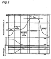
- This stage is called “pre-warming” in Fig. 2 .
- the moisture begins to evaporate from the biomass.
- the temperature of the biomass reaches the evaporation temperature, the free and loosely bound water evaporates from the biomass, while the temperature remains virtually constant.
- pre-drying in Fig. 2 .
- the biomass is dried in the dryer 3 until about 7-15% residual moisture content remains in it.
- the pre-dried biomass then leaves the dryer 3 through an outlet 7. Most of the energy of the hot gases introduced is used for drying the biomass, so its own temperature drops to 70-80°C.
- the cooled gases are removed from the dryer 3 through an outlet 8.
- the device 1 for treating biomass also comprises a torrefaction reactor 10.
- the torrefaction reactor according to the invention has an inlet 11 that is connected to the outlet 7 of the dryer 3.
- the pre-dried biomass can therefore be introduced into the torrefaction reactor 10 through the inlet 11.
- the torrefaction reactor 10 also has at least one inlet orifice 12.
- a hot gas flows through the inlet orifice 12 into the torrefaction reactor 10, so that heat transfer takes place by direct contact between the hot gas and the biomass.
- the torrefaction reactor can also be constructed for an indirect heat exchange between the hot gas and the biomass.
- Fig. 2 shows that the temperature of the biomass must first rise before torrefaction can take place. After all, the minimum temperature needed for torrefaction is about 200°C. As the temperature rises, the bound water evaporates from the biomass until the biomass is virtually free of moisture. This stage is called “post-drying and heating" in Fig. 2 . This post-drying and heating is carried out according to the invention in a drying chamber of the torrefaction reactor, which will be explained in more detail later with the aid of Fig. 3 .
- the biomass will then be torrefied (see "torrefaction" in Fig. 2 ) in a torrefying chamber of the torrefaction reactor.
- the temperature T torr can be regulated and affects the properties of the biomass fuel.
- the product quality of the torrefied biomass is reached at point A, but generally not enough combustible torrefaction gases have formed yet.
- the maximum torrefying temperature T torr is maintained beyond this point A, so that the amount of combustible torrefaction gases increases in the torrefaction reactor 10.
- the quality of the torrefied biomass is also improved here further.
- the combustible torrefaction gases leave the torrefaction reactor 10 through at least one outlet orifice 14.
- the outlet orifice 14 is connected to a combustion unit 20 with the aid of a pipe 16.
- the combustion unit 20 has an air inlet 22.
- the torrefaction gases introduced into the combustion unit 20 burn therein, which gives rise to a very hot flue gas.
- the flue gas has a temperature, for example, that lies in the range of 1000-1600°C, being e.g. 1200°C.
- the combustion unit 20 has an outlet 24 for the removal of this flue gas.
- the combustion unit 20 may also have an inlet 23 for additional fuel. The inlet 23 is desirable for example when the torrefying gases are not combustible or give rise to a flue gas that is not hot enough.
- the device I shown in Fig. 1 for treating biomass also comprises a heat exchanger 30.
- the heat exchanger 30 has an inlet 32 for hot flue gas, which inlet is connected to the outlet 24 of the combustion unit 20 with the aid of a pipe 25.
- the heat exchanger 30 has an inlet 33 for torrefaction gas.
- a fan 18 is provided in the branch line 17. Therefore, part of the torrefaction gas leaving the torrefaction reactor 10 flows into the heat exchanger 30 through the branch line 17, the fan 18 and the inlet 33.
- the flue gas entering through inlet 32 raises the temperature of the torrefaction gas to about 200-400°C. As a result of this the flue gas itself cools down to about 500-1000°C.
- the cooled flue gas then leaves the heat exchanger 30 through outlet 34, which is connected to the inlet 6 of the dryer 3.
- the heat exchanger can be either of the direct or the indirect type.
- direct heat exchange the torrefaction gas and the flue gas are in direct contact with each other.
- indirect heat exchanger the hot flue gas at a temperature of 1000-1600°C is used to heat e.g. an oil to 250-400°C, and the hot oil then heats up the torrefying gas. After that, this heated torrefaction gas flows into the torrefying chamber through the inlet orifice 12.
- the torrefied biomass is removed from the torrefaction reactor 10 through an outlet 13.
- the torrefied biomass is then conveyed to a cooler 40, where the biomass can cool down to room temperature. This is indicated by "cooling" in Fig. 2 .
- Fig. 1 shows the torrefaction reactor 10 schematically in the form of a single block diagram
- the torrefaction reactor 10 according to the invention comprises at least two reactor spaces.
- the first reactor space provides the drying chamber, while the second reactor space forms the torrefying chamber.
- the torrefaction reactor 10 according to the invention is shown in Fig. 3 in more detail.
- the torrefaction reactor 10 is essentially in the vertical position when it is in operation.
- the torrefaction reactor 10 comprises a peripheral wall 50, a bottom section 51 and a top section 52.
- the inlet 11 for introducing biomass into the torrefaction reactor 10 is located at one side of the bottom section 51.
- the bottom section 51 comprises a feed device 53 for conveying the biomass upwards within the peripheral wall 50.
- the feed device 53 is shown schematically in Fig. 3 .
- the peripheral wall 50 in the torrefaction reactor is filled with biomass during operation.
- the feed device 53 can have various designs.
- the feed device comprises two pistons and a supporting valve.
- the first piston can move through the inlet 11 to push in biomass for the second piston, which can move up and down within the peripheral wall.
- the supporting valve can move between a supporting position and a free position. When the piston has reached the end of its stroke, the supporting valve moves over to the supporting position to support the biomass within the peripheral wall.
- the second piston can then move downwards, after which the first piston can again load a quantity of biomass on it.
- the feed device can also be designed as a conveyer screw.
- the design of the feed device 53 depends on the orientation of the torrefaction reaction, which can be essentially vertical, horizontal or inclined at an angle between the two.
- the torrefaction reactor 10 is divided into a first reaction space or drying chamber 54 for the evaporation of residual moisture from the biomass, and a second reaction space or torrefying chamber 55 for torrefaction of the biomass.
- a first reaction space or drying chamber 54 for the evaporation of residual moisture from the biomass
- a second reaction space or torrefying chamber 55 for torrefaction of the biomass.
- the transition between the reaction spaces 54 and 55 is indicated by the dashed line C.
- the drying chamber 54 and the torrefying chamber 55 are therefore not enclosed chambers but form a continuous drying space 54 and torrefying space 55.
- the drying chamber 54 is therefore located between the biomass inlet 11 and the torrefying chamber 55.
- the drying chamber 54 has a number of inlet orifices 12a for the introduction of a hot drying gas.
- the drying gas introduced comes from the heat exchanger 30 (see Fig. 1 ) and has a temperature of e.g. 100-400°C.
- the drying gas and the biomass move in co-current with each other in the drying chamber 54.
- the drying gas can penetrate to the biomass at the location of the core within the peripheral wall.
- the drying gas that is introduced through the top inlet orifice 12a forms a stream of hot gas along the inside of the peripheral wall 50. Owing to this flow, the drying gas that has been introduced through the inlet orifice 12a below the first one is forced to move away from the peripheral wall 50 and is directed radially inward. This is indicated schematically by the arrows D. This ensures that not only the biomass by the peripheral wall but also the biomass in the middle is able to dry fully.
- the biomass When the biomass surpasses the level indicated by the dashed line C, the biomass is almost fully dry, i.e. the residual moisture has almost completely evaporated from the biomass.
- the moisture content of the biomass is then preferably ⁇ 3%.
- the temperature of the biomass has risen to about 200°C at the same time. Therefore, what happens above the level shown by the dashed line C is torrefaction.
- the biomass is then located in the torrefying chamber 55 for torrefying the biomass.
- the torrefying chamber 55 has inlet orifices 12b for torrefying gas, which are located in the top section 52 of the torrefaction reactor 10.
- the torrefying gas is the hot gas introduced into the torrefying chamber to torrefy the biomass.
- the torrefying gas is derived from the heat exchanger 30 (see Fig. 1 ), just like the drying gas.
- the torrefying gas flows from the inlet orifices 12b downwards through the biomass.
- the torrefying gas moves in counter-current to the biomass.
- the biomass is torrefied as it moves upward.
- the gas mixture leaving the torrefaction reactor 10 through the outlet orifices 14 will therefore contain relatively little steam according to the invention.
- the flow in the pipe 16 and the branch line 17 (see Fig. 1 ) is therefore relatively limited, which reduces the required power of the fan 18.
- the discharged combustible torrefaction gas will be hardly diluted with steam from the drying chamber 54, if at all. This has a favourable effect on the burning properties in the combustion unit 20 (see Fig. 1 ).
- the torrefaction reactor 10 has an overflow part 58. As the torrefied biomass is pushed over the edge of the overflow part 58, it overbalances along the overflow part 58 and falls into the cooling unit 40.
- the cooling unit has an inlet orifice 41 for the introduction of cooling gas. The temperature of the torrefied biomass decreases to room temperature in the cooling chamber 40. The cooled biomass leaves the cooling unit 40 through the outlet 42.
- Fig. 4 shows the temperature of the biomass, the drying gas and the torrefying gas as a function of the height z inside the torrefaction reactor (see Fig. 3 ).
- the temperature of the biomass is shown by the lowest line E, while the temperature of the drying gas and the temperature of the torrefying gas are shown by lines F and G, respectively.
- the separation between the drying chamber 54 and the torrefying chamber 55 is again shown by a dashed line C.
- Fig. 4 refers to the process according to the invention as described in the case of Fig. 3 .
- the biomass and the drying gas move in the drying chamber 54 in co-current with each other.
- the residual moisture can be eliminated from the biomass quickly and efficiently.
- the biomass and the torrefying gas introduced move in counter-current to each other. This makes it possible to control the maximum torrefying temperature accurately.
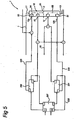
- Fig. 5 shows a second embodiment of a device for treating biomass, where the same reference numerals denote the same parts.
- the operation and construction essentially corresponds to the process and device for treating biomass as described above, and this embodiment also has the advantages mentioned above.
- the embodiment illustrated in Fig. 5 will be described below further as follows.
- the dryer used for pre-drying the biomass is not shown in Fig. 5 .
- the biomass, whether pre-dried or not, is introduced into the torrefaction reactor 10 through the inlet 11.
- the torrefaction reactor 10 is essentially vertical. Within the peripheral wall 50, the biomass moves downward under the influence of gravity. After all, the inlet 11 is located in the top section 52 of the torrefaction reactor 10, while the outlet 13 is in its bottom section 51.
- the top section of the torrefaction reactor 10 forms the drying chamber 54, while the bottom section of the torrefaction reactor 10 defines the torrefying chamber 55.
- the drying chamber 54 is located between the biomass inlet 11 and the torrefying chamber 55.
- the torrefying chamber 55 is bounded between the drying chamber 54 and the biomass outlet 13.
- the drying chamber 54 has one or more inlet orifices 12a.
- a hot drying gas flows into the drying chamber 54 of the torrefaction reactor 10 through the inlet orifices 12a, so that heat transfer takes place by direct contact between the hot drying gas and the biomass.
- the drying chamber can also be designed according to the invention for indirect heat exchange between the hot drying gas and the biomass.
- the drying gas and the biomass move in the drying chamber 54 in co-current with each other.
- Preferably a number of inlet orifices 12a are provided, one above the other, so that the drying gas can penetrate to the biomass at the location of the core (not shown in Fig. 5 ).
- the hot drying gas raises the temperature of the biomass in the drying chamber 54 and evaporates the bound water from the biomass until the biomass is almost free of moisture. This stage is indicated in Fig. 2 by "post-drying and heating".
- the hot drying gas is cooled in the process.
- the cooled drying gas is then introduced into a first heat exchanger 200.
- the first heat exchanger 200 heats the drying gas, and this heated drying gas is then again introduced into the drying chamber 54 through the inlet orifices 12a. This forms a first circuit 203, in which the drying gas circulates.
- the biomass descends from the drying chamber 54 into the torrefying chamber 55 of the torrefaction reactor, i.e. the biomass surpasses the level indicated by the dashed line C.
- the biomass is then almost completely dry, i.e. the residual moisture has been almost fully evaporated from the biomass.
- the biomass now contains e.g. ⁇ 3% of moisture.
- the temperature of the biomass will have risen to about 200°C at the same time.
- a hot torrefying gas is passed into the torrefying chamber 55 through the inlet orifices 12b.
- the torrefying gas is the hot gas that is introduced into the torrefying chamber 55 to torrefy the biomass.
- the torrefying gas moves from the inlet orifices 12b upward through the biomass.
- the torrefying gas and the biomass move in counter-current to each other.
- the biomass will be torrefied as it moves downward.
- Combustible torrefaction gases are formed when the biomass is heated to the maximum torrefying temperature T torr in the second reaction space 55.
- the amount of combustible torrefaction gas increases by maintaining this temperature for some time.
- the torrefying gas introduced and the torrefaction gases formed leave the torrefying chamber 55 through the outlet orifices 14.
- the outlet orifices 14 are connected to the pipe 16 with the aid of a branch line, and pipe 16 is connected to a combustion unit 20 (not shown in Fig. 5 ).
- the outlet orifices 14 are likewise connected to a second heat exchanger 201, and part of the torrefaction gas formed is passed into the second heat exchanger 201.
- the heat exchanger 201 heats up the torrefaction gas, and the heated torrefaction gas is introduced into the torrefying chamber 55 through the inlet orifices 12b.
- the torrefaction gas formed is used as the torrefying gas. This gas is recirculated in a second circuit 205.
- the temperature profile shown in Fig. 4 also applies to the embodiment illustrated in Fig. 5 .
- the biomass and the drying gas move in the drying chamber 54 in co-current with each other. As a result the residual moisture can be eliminated from the biomass quickly and efficiently.
- the biomass and the torrefying gas supplied move in counter-current to each other. This makes it possible to control the maximum torrefying temperature accurately.
- the heating of the drying gas and the torrefying gas in the respective heat exchangers 200 and 201 can be carried out with the aid of a third circuit 209, which comprises a heating unit 207.
- the heating unit 207 can be e.g. an oil boiler, in which case hot oil is circulated in the third circuit 209, including the heat exchangers 200 and 201. This is made possible by the use of a co-current flow in the drying chamber 54 and a counter-current flow in the torrefying chamber 55, in which case the temperatures of the drying gas and the torrefying gas remain relatively low.
- the torrefied biomass is removed from the torrefaction reactor 10 through the outlet 13.
- the torrefied biomass is then transferred to a cooler 40 (not shown in Fig. 5 ), where the biomass can be cooled down to room temperature. This is indicated in Fig. 2 by "cooling".
- the drying chamber 54 and the torrefying chamber 55 can be made as separate entities, connected to each other by a pipe.
- the drying chamber 54 is then housed in a separate residual-moisture dryer, while the torrefying chamber 55 is incorporated in the torrefaction reactor 10.
- the residual-moisture dryer in the system illustrated in Fig. 1 is inserted between the preliminary dryer 3 and the torrefaction reactor 10.
Claims (15)
- Procédé pour traiter un matériau, tel qu'une biomasse ou des déchets, comprenant :- la fourniture d'un matériau qui contient une quantité d'humidité résiduelle,- la fourniture d'un réacteur de torréfaction (10),- le chauffage du matériau dans le réacteur de torréfaction (10) à une température de torréfaction dans une atmosphère pauvre en oxygène dans le réacteur de torréfaction (10),où le matériau est converti en matériau torréfié,
caractérisé en ce que le matériau avec l'humidité résiduelle contenue dans celui-ci est pratiquement totalement séché dans une chambre de séchage (54) par évaporation de l'humidité résiduelle, et la torréfaction du matériau séché est essentiellement conduite dans une chambre de torréfaction (55) du réacteur de torréfaction (10) dans une direction de transport (B), et le séchage du matériau dans la chambre de séchage (54) est conduit en introduisant dans celle-ci un gaz de séchage chaud qui s'écoule à travers la chambre de séchage (54) en co-courant avec le matériau, et la torréfaction du matériau dans la chambre de torréfaction (55) du réacteur de torréfaction est conduite en introduisant dans celle-ci un gaz de torréfaction chaud qui s'écoule à travers la chambre de torréfaction (55) du réacteur de torréfaction (10) à contre-courant par rapport au matériau. - Procédé selon la revendication 1, dans lequel le réacteur de torréfaction (10) comprend la chambre de séchage (54) et la chambre de torréfaction (55).
- Procédé selon la revendication 1, dans lequel la chambre de séchage est logée dans un séchoir d'humidité résiduelle, et la chambre de torréfaction est logée dans le réacteur de torréfaction.
- Procédé selon l'une quelconque des revendications précédentes, dans lequel le matériau contient des particules solides qui se déplacent à travers le réacteur de torréfaction (10) sous la forme d'un lit à garnissage fixe.
- Procédé selon l'une quelconque des revendications précédentes, dans lequel le gaz de séchage après avoir été déplacé en co-courant avec le matériau et a été refroidi ainsi quitte la chambre de séchage et est introduit dans un premier échangeur de chaleur, qui chauffe ce gaz de séchage, après quoi le gaz de séchage chauffé par le premier échangeur de chaleur est introduit dans la chambre de séchage (54), et le gaz de torréfaction, après avoir été déplacé en contre-courant par rapport au matériau et a ainsi été refroidi quitte la chambre de torréfaction et est introduit dans un deuxième échangeur de chaleur, qui chauffe ce gaz de torréfaction, après quoi le gaz de torréfaction qui a été chauffé par le deuxième échangeur de chaleur est introduit dans la chambre de torréfaction (54).
- Procédé selon l'une quelconque des revendications précédentes, dans lequel la fourniture du matériau comprend l'introduction d'un matériau relativement humide dans un séchoir (3), et le chauffage du matériau dans le séchoir (3) pour évaporer l'humidité du matériau jusqu'à ce que la quantité d'humidité résiduelle reste dans le matériau, le matériau qui a été séché dans le séchoir (3) étant introduit dans la chambre de séchage (54).
- Procédé selon l'une quelconque des revendications précédentes, dans lequel la température du gaz chaud introduit dans la chambre de torréfaction (55) est dans la plage de 200 à 400 °C, par exemple, environ 300 °C.
- Procédé selon l'une quelconque des revendications précédentes, dans lequel la température du gaz chaud introduit dans la chambre de séchage (54) est dans la plage de 150 à 600 °C, par exemple, environ 350 °C.
- Dispositif pour traiter un matériau, tel qu'une biomasse ou des déchets, ledit dispositif comprend un réacteur de torréfaction (10) qui peut être alimenté avec un matériau qui contient une quantité d'humidité résiduelle, ledit réacteur de torréfaction (10) est pourvu d'une entrée (11) pour introduire ce matériau dans le réacteur de torréfaction (10), de moyens de chauffage (12) pour chauffer le matériau dans le réacteur de torréfaction (10) à une température de torréfaction, de moyens de traitement d'air pour créer une atmosphère pauvre en oxygène dans le réacteur de torréfaction où le matériau peut être converti en matériau torréfié pendant le fonctionnement, et d'une sortie (13) pour enlever le matériau torréfié,
caractérisé en ce que le réacteur de torréfaction (10) comprend une chambre de séchage (54) et une chambre de torréfaction (55), ladite chambre de séchage (54) est adaptée pour le séchage pratiquement total du matériau par évaporation de l'humidité résiduelle et ladite chambre de torréfaction (55) est adaptée pour torréfier le matériau, et où la chambre de torréfaction (55) est située en aval de la chambre de séchage (54) lorsqu'elle est observée dans la direction de circulation du matériau, et où la chambre de séchage (54) a au moins un orifice d'entrée (12a) pour un gaz de séchage et au moins un orifice de sortie (15) pour ledit gaz de séchage et éventuellement un gaz et/ou une vapeur formé pendant l'évaporation de l'humidité résiduelle, ledit orifice d'entrée (12a) pour le gaz de séchage est situé à l'extrémité de la chambre de séchage (54) qui fait face à l'entrée (11), et l'orifice de sortie (15) est situé à l'extrémité opposée de la chambre de séchage (54), et où la chambre de torréfaction (55) a au moins un orifice d'entrée (12b) pour le gaz de torréfaction et au moins un orifice de sortie (14) pour ledit gaz de torréfaction et le gaz de torréfaction formé dans le procédé de torréfaction, ledit orifice d'entrée (12b) pour le gaz de torréfaction est situé à l'extrémité de la chambre de torréfaction (55) qui fait face à la sortie (13) et l'orifice de sortie (14) est situé à l'extrémité opposée de la chambre de torréfaction (55),
lesdites orifices de sortie (14, 15) étant situé entre ladite au moins un orifice d'entrée (12a) de la chambre de séchage (54) et ladite au moins un orifice d'entrée (12b) de la chambre de torréfaction (55),
et en ce que le réacteur comprend en outre deux échangeurs de chaleur, où le premier échangeur de chaleur est disposé pour chauffer le gaz de séchage et est raccordé à l'orifice d'entrée et l'orifice de sortie de la chambre de séchage afin de former un circuit de gaz de séchage, et le deuxième échangeur de chaleur est disposé pour chauffer le gaz de torréfaction et est raccordé à l'orifice d'entrée et l'orifice de sortie de la chambre de torréfaction pour former un circuit de gaz de torréfaction. - Dispositif selon la revendication 9, dans lequel un séchoir (3) est disposé qui peut être alimenté avec un matériau relativement humide, qui est équipé de moyens de chauffage (6) pour chauffer ce matériau afin d'évaporer l'humidité du matériau jusqu'à ce que la quantité d'humidité résiduelle reste dans le matériau, et dans lequel le séchoir (3) est raccordé à la chambre de séchage (54) pour introduire le matériau séché dans le séchoir (3) dans la chambre de séchage (54).
- Dispositif selon l'une quelconque des revendications 9 à 10, dans lequel, lorsqu'il est observé dans la direction de circulation du matériau, la chambre de séchage (54) est située entre l'entrée (11) pour le matériau et la chambre de torréfaction (55), et la chambre de torréfaction (55) est située entre la chambre de séchage (54) et la sortie (13) pour le matériau torréfié.
- Dispositif selon l'une quelconque des revendications 9 à 11, dans lequel le réacteur de torréfaction (10) est délimité par une paroi périphérique (50), et la chambre de séchage (54) et la chambre de torréfaction (55) s'étendent sous la forme d'un prolongement l'une de l'autre dans la paroi périphérique (50).
- Dispositif selon la revendication 12, dans lequel le réacteur de torréfaction (10) est monté dans la position verticale, et dans lequel une pluralité d'orifices d'entrée (12a) sont disposés dans la paroi périphérique (50), les uns au-dessus des autres, pour l'introduction de gaz de séchage.
- Dispositif selon l'une quelconque des revendications 9 à 13, dans lequel la sortie (13) est raccordée à une chambre de refroidissement (40), et dans lequel le matériau torréfié peut être introduit depuis la chambre de torréfaction (55) dans la chambre de refroidissement (40).
- Dispositif selon la revendication 14, dans lequel la chambre de refroidissement (40) est pourvue d'orifices d'entrée (41) pour l'introduction de gaz de refroidissement.
Priority Applications (2)
| Application Number | Priority Date | Filing Date | Title |
|---|---|---|---|
| SI200730886T SI1969099T1 (sl) | 2006-01-06 | 2007-01-08 | Postopek in naprava za obdelavo biomase |
| PL07709151T PL1969099T5 (pl) | 2006-01-06 | 2007-01-08 | Sposób i urządzenie do obróbki biomasy |
Applications Claiming Priority (2)
| Application Number | Priority Date | Filing Date | Title |
|---|---|---|---|
| NL1030864A NL1030864C2 (nl) | 2006-01-06 | 2006-01-06 | Werkwijze en inrichting voor het behandelen van biomassa. |
| PCT/NL2007/050003 WO2007078199A1 (fr) | 2006-01-06 | 2007-01-08 | Processus et dispositif de traitement de biomasse |
Publications (3)
| Publication Number | Publication Date |
|---|---|
| EP1969099A1 EP1969099A1 (fr) | 2008-09-17 |
| EP1969099B1 EP1969099B1 (fr) | 2012-02-08 |
| EP1969099B2 true EP1969099B2 (fr) | 2017-03-22 |
Family
ID=36940727
Family Applications (1)
| Application Number | Title | Priority Date | Filing Date |
|---|---|---|---|
| EP07709151.0A Active EP1969099B2 (fr) | 2006-01-06 | 2007-01-08 | Processus et dispositif de traitement de biomasse |
Country Status (27)
| Country | Link |
|---|---|
| US (1) | US8105400B2 (fr) |
| EP (1) | EP1969099B2 (fr) |
| JP (1) | JP5118060B2 (fr) |
| CN (1) | CN101379167B (fr) |
| AP (1) | AP2469A (fr) |
| AT (1) | ATE544835T2 (fr) |
| AU (1) | AU2007203837B2 (fr) |
| BR (1) | BRPI0706225B1 (fr) |
| CA (1) | CA2636285C (fr) |
| CR (1) | CR10131A (fr) |
| DK (1) | DK1969099T4 (fr) |
| EA (1) | EA012806B1 (fr) |
| ES (1) | ES2380961T5 (fr) |
| HN (1) | HN2008001023A (fr) |
| HR (1) | HRP20120203T1 (fr) |
| MX (1) | MX2008008751A (fr) |
| MY (1) | MY162050A (fr) |
| NL (1) | NL1030864C2 (fr) |
| NO (1) | NO341548B1 (fr) |
| NZ (1) | NZ569611A (fr) |
| PL (1) | PL1969099T5 (fr) |
| PT (1) | PT1969099E (fr) |
| RS (1) | RS52254B (fr) |
| SI (1) | SI1969099T1 (fr) |
| UA (1) | UA91888C2 (fr) |
| WO (1) | WO2007078199A1 (fr) |
| ZA (1) | ZA200805887B (fr) |
Families Citing this family (80)
| Publication number | Priority date | Publication date | Assignee | Title |
|---|---|---|---|---|
| US8197561B2 (en) * | 2001-10-10 | 2012-06-12 | River Basin Energy, Inc. | Process for drying coal |
| CA2561665A1 (fr) * | 2004-04-02 | 2005-10-20 | Skill Associates, Inc. | Convertisseurs de biomasse et procedes associes |
| US9264976B2 (en) | 2007-11-16 | 2016-02-16 | Qualcomm Incorporated | Preamble design for a wireless signal |
| US8918112B2 (en) | 2007-11-16 | 2014-12-23 | Qualcomm Incorporated | Preamble design for a wireless signal |
| US9215669B2 (en) | 2007-11-16 | 2015-12-15 | Qualcomm Incorporated | Preamble design for a wireless signal |
| US9801188B2 (en) | 2008-02-01 | 2017-10-24 | Qualcomm Incorporated | Backhaul signaling for interference avoidance |
| US8768372B2 (en) | 2008-02-13 | 2014-07-01 | Qualcomm Incorporated | Sector interference management based on inter-sector performance |
| KR20100136534A (ko) | 2008-04-03 | 2010-12-28 | 노쓰 캐롤라이나 스테이트 유니버시티 | 자열 및 이동식의 건조 장치 |
| US20090293303A1 (en) * | 2008-06-03 | 2009-12-03 | Synagro Technologies, Inc. | Biosolid Drying and Utilization in Cement Processes |
| SE532746C2 (sv) * | 2008-06-11 | 2010-03-30 | Bio Energy Dev North Ab | Förfarande och apparatur för framställning av torrefierat lignocellulosamaterial |
| US8161663B2 (en) | 2008-10-03 | 2012-04-24 | Wyssmont Co. Inc. | System and method for drying and torrefaction |
| US8669404B2 (en) | 2008-10-15 | 2014-03-11 | Renewable Fuel Technologies, Inc. | Method for conversion of biomass to biofuel |
| EP2189512A1 (fr) | 2008-11-24 | 2010-05-26 | Sa Cockerill Maintenance Et Ingenierie | Procédé de torrefaction de la biomasse et controle de celui-ci |
| US8276289B2 (en) * | 2009-03-27 | 2012-10-02 | Terra Green Energy, Llc | System and method for preparation of solid biomass by torrefaction |
| FI20090183A0 (fi) * | 2009-05-08 | 2009-05-08 | Markku Olavi Raiko | Menetelmä biomassan termiseksi käsittelemiseksi lämpökattilan yhteydessä |
| EA201200082A1 (ru) * | 2009-07-02 | 2012-07-30 | Гершон Бен-Товим | Сушильный аппарат |
| US8974471B2 (en) | 2009-07-16 | 2015-03-10 | Circ Medtech Ltd. | Circumcision device and method for mass circumcision |
| US8449724B2 (en) | 2009-08-19 | 2013-05-28 | Andritz Technology And Asset Management Gmbh | Method and system for the torrefaction of lignocellulosic material |
| FR2952068B1 (fr) * | 2009-10-30 | 2012-09-28 | Olivecoal Concept | Procede de fabrication d'un combustible par torrefaction de grignon d'olive |
| BR112012011205A2 (pt) * | 2009-11-16 | 2018-04-10 | Thyssenkrupp Uhde Gmbh | dispositivo para a produção de um combustível de grão fino, processo para a produção de um combustível de grão fino e utilização de um combustível produzido de acordo com um processo |
| DE102009053059A1 (de) | 2009-11-16 | 2011-05-19 | Schäfer Elektrotechnik und Sondermaschinen GmbH | Vorrichtung und Verfahren zur Erzeugung eines feinkörnigen Brennstoffs aus festen oder pastösen Energierohstoffen durch Torrefizierung und Zerkleinerung |
| US8647586B2 (en) | 2010-03-08 | 2014-02-11 | Renewable Fuel Technologies, Inc. | Device for conversion of biomass to biofuel |
| US8956426B2 (en) | 2010-04-20 | 2015-02-17 | River Basin Energy, Inc. | Method of drying biomass |
| US9057037B2 (en) | 2010-04-20 | 2015-06-16 | River Basin Energy, Inc. | Post torrefaction biomass pelletization |
| US20110252698A1 (en) * | 2010-04-20 | 2011-10-20 | River Basin Energy, Inc. | Method of Drying Biomass |
| US20110314728A1 (en) * | 2010-06-24 | 2011-12-29 | River Basin Energy, Inc. | Method of Simultaneously Drying Coal and Torrefying Biomass |
| CN103249817B (zh) | 2010-07-29 | 2015-08-26 | 中央研究院 | 生质变成生质煤的超级烘焙法 |
| US8246788B2 (en) | 2010-10-08 | 2012-08-21 | Teal Sales Incorporated | Biomass torrefaction system and method |
| US10377954B2 (en) * | 2010-11-09 | 2019-08-13 | Board Of Regents Of The Nevada System Of Higher Education, On Behalf Of The University Of Nevada, Reno | Method for wet torrefaction of a biomass |
| NL2005716C2 (en) * | 2010-11-18 | 2012-03-12 | Stichting Energie | Torrefying device and process for the thermal treatment of organic material. |
| JP5584647B2 (ja) * | 2011-04-08 | 2014-09-03 | 株式会社日立製作所 | バイオマスの半炭化燃料の製造装置と製造方法、及び半炭化燃料を用いた発電システム |
| PL2697185T3 (pl) | 2011-04-15 | 2020-12-28 | Carbon Technology Holdings, LLC | Sposoby wytwarzania wysokowęglowych odczynników biogenicznych |
| US9580665B2 (en) | 2011-05-18 | 2017-02-28 | Bioendev Ab | Countercurrent oxygen enhanced torrefaction |
| LT2710099T (lt) | 2011-05-18 | 2016-12-12 | Bioendev Ab | Torefikacijos temperatūros stebėjimo ir kontrolės būdas |
| WO2012158111A1 (fr) * | 2011-05-18 | 2012-11-22 | Bioendev Ab | Procédé de refroidissement d'un matériau torréfié |
| US20140325900A1 (en) * | 2011-05-18 | 2014-11-06 | Bioendev Ab | Method and an arrangement for efficient torrefaction of biomass |
| WO2012158115A2 (fr) * | 2011-05-18 | 2012-11-22 | Bioendev Ab | Élimination de l'humidité dans une étape de préséchage au cours d'un processus de torréfaction |
| WO2012166771A2 (fr) | 2011-05-30 | 2012-12-06 | Washington State University Research Foundation | Traitement de biomasse utilisant un traitement thermochimique et une digestion anaérobie en combinaison |
| WO2013019111A1 (fr) | 2011-08-01 | 2013-02-07 | Stichting Energieonderzoek Centrum Nederland | Utilisation d'un condensat de torréfaction |
| US8203024B2 (en) * | 2011-08-23 | 2012-06-19 | Advanced Toffefaction Systems, LLC | Torrefaction systems and methods including catalytic oxidation and/or reuse of combustion gases directly in a torrefaction reactor, cooler, and/or dryer/preheater |
| WO2013040305A1 (fr) * | 2011-09-16 | 2013-03-21 | Astec, Inc. | Procédé et appareil permettant de traiter une matière de biomasse |
| US9127227B2 (en) | 2011-09-16 | 2015-09-08 | Astec, Inc. | Method and apparatus for processing biomass material |
| US8198493B1 (en) | 2012-01-11 | 2012-06-12 | Earth Care Products, Inc. | High energy efficiency biomass conversion process |
| NL2008682C2 (en) | 2012-04-23 | 2013-10-31 | Stichting Energie | Wet biomass treatment. |
| EP3702325A1 (fr) | 2012-05-07 | 2020-09-02 | Carbon Technology Holdings, LLC | Procédé de fabrication d'energie |
| TWI447598B (zh) * | 2012-06-13 | 2014-08-01 | China Steel Corp | 生質物之乾燥方法與其電腦程式產品 |
| US9562204B2 (en) | 2012-09-14 | 2017-02-07 | Astec, Inc. | Method and apparatus for pelletizing blends of biomass materials for use as fuel |
| DK2912150T3 (da) * | 2012-10-25 | 2017-11-06 | Astec Inc | Fremgangsmåde og indretning til pelletering af blandinger af biomassematerialer til anvendelse som brændstof |
| US9175235B2 (en) | 2012-11-15 | 2015-11-03 | University Of Georgia Research Foundation, Inc. | Torrefaction reduction of coke formation on catalysts used in esterification and cracking of biofuels from pyrolysed lignocellulosic feedstocks |
| NO342736B1 (no) * | 2013-02-20 | 2018-08-06 | Arbaflame Tech As | Fremgangsmåte og apparatur for fremstilling av brensel fra biomasse |
| PL404037A1 (pl) | 2013-05-22 | 2014-11-24 | Boneffice Spółka Z Ograniczoną Odpowiedzialnością | Sposób prowadzenia procesu toryfikacji biomasy, instalacja do prowadzenia procesu toryfikacji biomasy, toryfikowana biomasa oraz sposób oczyszczania gazów wylotowych z procesu toryfikacji |
| JP5603477B1 (ja) * | 2013-08-05 | 2014-10-08 | 株式会社アイエムティ | 連続炭化装置 |
| WO2015061701A1 (fr) | 2013-10-24 | 2015-04-30 | Biogenic Reagent Ventures, Llc | Procédés et appareil pour produire du charbon actif à partir de biomasse par le biais d'intermédiaires de cendre carbonisée |
| FR3015513B1 (fr) * | 2013-12-19 | 2016-01-01 | Axens | Procede de torrefaction d'une charge carbonee comprenant une etape de sechage optimisee |
| CN103756745B (zh) * | 2014-01-03 | 2015-09-02 | 张家港天源生物能源科技有限公司 | 生物质烘焙方法 |
| DK3094593T3 (da) | 2014-01-16 | 2022-04-11 | Carbon Tech Holdings Llc | Kulstofmikroanlæg |
| CN104841338A (zh) * | 2014-02-14 | 2015-08-19 | 上海金匙环保科技股份有限公司 | 出料装置及具有出料装置的热解处理系统 |
| WO2015127460A1 (fr) | 2014-02-24 | 2015-08-27 | Biogenic Reagent Ventures, Llc | Charbon actif extrêmement mésoporeux |
| CN105018123B (zh) * | 2014-04-30 | 2017-12-19 | 代建军 | 一种提高生物质受热均匀性和热效率的烘焙方法和系统 |
| SE538488C2 (en) * | 2014-09-18 | 2016-08-02 | Tomas Åbyhammar Med Enskild Firma Scandry | Method for thermal treatment of raw materials comprising lignocellulose |
| WO2016046580A1 (fr) | 2014-09-23 | 2016-03-31 | Bon Effice Sp. Z O.O. | Dispositif pour traiter des matières; et ensemble, installation et procédé permettant d'effectuer un processus de torréfaction |
| KR101573677B1 (ko) * | 2014-10-10 | 2015-12-02 | 한국에너지기술연구원 | 바이오매스 반탄화를 위한 역흐름 다중 방해판 열분해장치 |
| WO2016065357A1 (fr) | 2014-10-24 | 2016-04-28 | Biogenic Reagent Ventures, Llc | Compositions halogénées de charbon actif et leurs procédés de préparation et d'utilisation |
| WO2016065477A1 (fr) * | 2014-10-29 | 2016-05-06 | Gestion Viateur Girard Inc. | Procédé de torréfaction du bois, et matériau de construction produit par ce procédé |
| CA2973188A1 (fr) * | 2015-01-23 | 2016-07-28 | Bioendev Ab | Procede et systeme de torrefaction efficace d'une biomasse |
| CN104629850B (zh) * | 2015-02-06 | 2017-04-05 | 江苏大学 | 一种生物质发电装置及方法 |
| US10167428B2 (en) * | 2015-06-01 | 2019-01-01 | Central Michigan University | Methods for biomass torrefaction with carbon dioxide capture |
| CN104975167B (zh) * | 2015-07-24 | 2017-09-12 | 长沙矿冶研究院有限责任公司 | 一种含锰的多物相组成的复合锰矿提取锰的方法 |
| US10221359B2 (en) | 2016-09-20 | 2019-03-05 | Anthony Phan | Biomass treatment process and apparatus |
| JP2018075561A (ja) * | 2016-10-31 | 2018-05-17 | 北川工業株式会社 | 植物由来疎水化材料の製造方法、及び植物由来疎水化材料 |
| IT201700083676A1 (it) * | 2017-07-21 | 2019-01-21 | Sea Servizi Ecologici Ambientali S R L | Procedimento di torrefazione di fanghi biologici e relativo sistema. |
| GB2571991A (en) * | 2018-03-16 | 2019-09-18 | Wilson Bio Chemical Ltd | Processing waste into carbon char |
| HU231095B1 (hu) | 2018-03-29 | 2020-08-28 | Agricarbon Kft. | Eljárás és berendezés biomassza kezelésére |
| JP6843107B2 (ja) * | 2018-12-13 | 2021-03-17 | 中外炉工業株式会社 | トレファクション燃料製造システム |
| RU2707227C1 (ru) * | 2019-03-13 | 2019-11-25 | Федеральное государственное бюджетное образовательное учреждение высшего образования "Казанский государственный энергетический университет" (ФГБОУ ВО "КГЭУ") | Пиролизная установка |
| RU2714648C1 (ru) * | 2019-07-16 | 2020-02-18 | Смышляев Сергей Владимирович | Реактор для торрефикации древесного сырья |
| EP4217514A1 (fr) | 2020-09-25 | 2023-08-02 | Carbon Technology Holdings, LLC | Bioréduction de minerais métalliques intégrés à la pyrolyse de biomasse |
| CN112710146B (zh) * | 2021-02-01 | 2022-05-13 | 中国科学院广州能源研究所 | 一种混流两用的立式高湿有机固废烘干装置及方法 |
| KR20230145585A (ko) | 2021-02-18 | 2023-10-17 | 카본 테크놀로지 홀딩스, 엘엘씨 | 탄소-네거티브 야금 생성물 |
| CA3216762A1 (fr) | 2021-04-27 | 2022-11-03 | Carbon Technology Holdings, LLC | Compositions de biocarbone a carbone fixe optimise et leurs procedes de production |
Citations (11)
| Publication number | Priority date | Publication date | Assignee | Title |
|---|---|---|---|---|
| DE413817C (de) † | 1921-11-20 | 1925-05-22 | Buettner Werke Akt Ges Fa | Verfahren zum Trocknen und Roesten von Stoffen |
| DE2802213A1 (de) † | 1978-01-19 | 1979-07-26 | Fink Gerdinand | Verfahren und vorrichtung fuer die direktreduktion von eisenerz mit holz als reduktionsmittel |
| US4347156A (en) † | 1979-04-02 | 1982-08-31 | Lurgi Corporation | System and process for reactivating carbon |
| EP0067901A1 (fr) † | 1981-06-25 | 1982-12-29 | Deutsche Kommunal-Anlagen Miete GmbH | Procédé de fabrication d'un combustible solide, susceptible d'être stocké et sans odeur, à partir de déchets |
| DE3738665A1 (de) † | 1986-11-17 | 1988-05-26 | K Fuel Partnership | Vorrichtung mit mehreren herden und verfahren zur thermischen behandlung von kohlenstoffhaltigen materialien |
| DE3820913A1 (de) † | 1988-06-21 | 1989-12-28 | Metallgesellschaft Ag | Verfahren zum schwelen von holz zur erzeugung von holzkohle |
| DE3686727T2 (de) † | 1985-05-24 | 1993-04-22 | Clerc De Bussy Le | Verfahren zum erzeugen von geroestetem holz, auf diese weise hergestelltes produkt und dessen verwendung zum erzeugen von energie. |
| DE4319828A1 (de) † | 1993-06-16 | 1994-12-22 | Henkel Kgaa | Modifiziertes Trocknungsverfahren unter Mitverwendung von Heißdampf im Trocknungsmedium und seine Anwendung |
| DE4408455A1 (de) † | 1994-03-12 | 1995-09-14 | Metallgesellschaft Ag | Verfahren zum Erzeugen von Holzkohle im Wanderbett |
| DE10030778C2 (de) † | 2000-06-23 | 2002-11-14 | Nachhaltige Stoffnutzung Mbh G | Verfahren und Vorrichtung zur Erzeugung eines Brenngases aus Biomassen |
| EP1475429A1 (fr) † | 1999-05-21 | 2004-11-10 | Ebara Corporation | Système de génération d'énergie électrique par gazéification. |
Family Cites Families (21)
| Publication number | Priority date | Publication date | Assignee | Title |
|---|---|---|---|---|
| BE444413A (fr) * | ||||
| US4177740A (en) * | 1978-03-10 | 1979-12-11 | Enterprises International, Inc. | Apparatus for generating heat from waste fuel |
| DE3041627A1 (de) * | 1980-11-05 | 1982-06-09 | Artur Richard 6000 Frankfurt Greul | Verfahren zum aufarbeiten von zellulosehaltigen biomassen bzw. braunkohle und lignit zu einem einheitlichenk stark reaktionsfaehigen, staubfoermigen brennstoff |
| FR2512053B1 (fr) * | 1981-08-28 | 1985-08-02 | Armines | Procede de transformation de matiere ligneuse d'origine vegetale et matiere d'origine vegetale ligneuse transformee par torrefaction |
| DE3211590A1 (de) * | 1982-03-30 | 1983-10-13 | Artur Richard 6000 Frankfurt Greul | Verfahren und vorrichtung zum bertinisieren von biomassen |
| CN1015921B (zh) * | 1984-10-01 | 1992-03-18 | 佩勒伦·米尔诺公司 | 滚筒干燥机 |
| FR2591611B1 (fr) * | 1985-12-18 | 1988-11-10 | Armines | Nouveau materiau ligno-cellulosique thermocondense, procede et four pour l'obtenir. |
| FR2624876B1 (fr) * | 1987-12-22 | 1994-03-11 | Technology Exports Ltd | Procede et dispositif de torrefaction de matiere ligneuse vegetale |
| DE3803109C2 (de) * | 1988-02-03 | 1998-10-08 | Eirich Maschf Gustav | Verfahren zum Trocknen von feuchtem Material |
| CN1044333A (zh) * | 1989-01-17 | 1990-08-01 | 佐藤次郎 | 木材干燥的方法及其装置 |
| JP2969417B2 (ja) * | 1993-02-01 | 1999-11-02 | 健 黒木 | 廃プラスチックの分解方法 |
| US5993751A (en) * | 1998-06-02 | 1999-11-30 | Moriarty; Jack | Pyrolizer |
| JP3502339B2 (ja) * | 2000-10-04 | 2004-03-02 | アジアプラントサービス株式会社 | 廃棄物処理装置 |
| JP2003129062A (ja) * | 2001-10-23 | 2003-05-08 | Shizuoka Prefecture | 炭化物製造装置 |
| US20030221363A1 (en) * | 2002-05-21 | 2003-12-04 | Reed Thomas B. | Process and apparatus for making a densified torrefied fuel |
| JP3830096B2 (ja) * | 2002-06-04 | 2006-10-04 | 日本碍子株式会社 | 炭化システム |
| JP2004174426A (ja) * | 2002-11-28 | 2004-06-24 | Asia Plant Service Kk | 廃棄物処理装置 |
| JP2004330092A (ja) * | 2003-05-08 | 2004-11-25 | Hamada Seisakusho:Kk | 含水廃棄処理物の乾燥炭化処理方法及び乾燥炭化処理装置 |
| NL1025027C2 (nl) * | 2003-12-15 | 2005-06-21 | Stichting Energie | Werkwijze en stelsel voor de productie van vaste stoffen uit grondstoffen. |
| JP4472380B2 (ja) * | 2004-02-27 | 2010-06-02 | 住友大阪セメント株式会社 | バイオマス半炭化燃料の製造方法及び装置 |
| KR100569120B1 (ko) * | 2004-08-05 | 2006-04-10 | 한국에너지기술연구원 | 바이오메스 정제연료의 저온 촉매가스화 장치 및가스제조방법 |
-
2006
- 2006-01-06 NL NL1030864A patent/NL1030864C2/nl not_active IP Right Cessation
-
2007
- 2007-01-08 CN CN2007800047862A patent/CN101379167B/zh active Active
- 2007-01-08 RS RS20120150A patent/RS52254B/en unknown
- 2007-01-08 NZ NZ569611A patent/NZ569611A/en not_active IP Right Cessation
- 2007-01-08 PT PT07709151T patent/PT1969099E/pt unknown
- 2007-01-08 ES ES07709151.0T patent/ES2380961T5/es active Active
- 2007-01-08 WO PCT/NL2007/050003 patent/WO2007078199A1/fr active Application Filing
- 2007-01-08 JP JP2008549443A patent/JP5118060B2/ja active Active
- 2007-01-08 AT AT07709151T patent/ATE544835T2/de active
- 2007-01-08 PL PL07709151T patent/PL1969099T5/pl unknown
- 2007-01-08 US US12/160,106 patent/US8105400B2/en active Active
- 2007-01-08 MY MYPI20082511A patent/MY162050A/en unknown
- 2007-01-08 EA EA200870159A patent/EA012806B1/ru not_active IP Right Cessation
- 2007-01-08 AP AP2008004557A patent/AP2469A/xx active
- 2007-01-08 MX MX2008008751A patent/MX2008008751A/es active IP Right Grant
- 2007-01-08 CA CA2636285A patent/CA2636285C/fr active Active
- 2007-01-08 SI SI200730886T patent/SI1969099T1/sl unknown
- 2007-01-08 UA UAA200808845A patent/UA91888C2/ru unknown
- 2007-01-08 EP EP07709151.0A patent/EP1969099B2/fr active Active
- 2007-01-08 DK DK07709151.0T patent/DK1969099T4/en active
- 2007-01-08 AU AU2007203837A patent/AU2007203837B2/en active Active
- 2007-01-08 BR BRPI0706225A patent/BRPI0706225B1/pt active IP Right Grant
-
2008
- 2008-07-04 HN HN2008001023A patent/HN2008001023A/es unknown
- 2008-07-04 ZA ZA200805887A patent/ZA200805887B/xx unknown
- 2008-07-07 CR CR10131A patent/CR10131A/es unknown
- 2008-07-14 NO NO20083129A patent/NO341548B1/no unknown
-
2012
- 2012-03-01 HR HR20120203T patent/HRP20120203T1/hr unknown
Patent Citations (12)
| Publication number | Priority date | Publication date | Assignee | Title |
|---|---|---|---|---|
| DE413817C (de) † | 1921-11-20 | 1925-05-22 | Buettner Werke Akt Ges Fa | Verfahren zum Trocknen und Roesten von Stoffen |
| DE2802213A1 (de) † | 1978-01-19 | 1979-07-26 | Fink Gerdinand | Verfahren und vorrichtung fuer die direktreduktion von eisenerz mit holz als reduktionsmittel |
| US4347156A (en) † | 1979-04-02 | 1982-08-31 | Lurgi Corporation | System and process for reactivating carbon |
| EP0067901A1 (fr) † | 1981-06-25 | 1982-12-29 | Deutsche Kommunal-Anlagen Miete GmbH | Procédé de fabrication d'un combustible solide, susceptible d'être stocké et sans odeur, à partir de déchets |
| DE3686727T2 (de) † | 1985-05-24 | 1993-04-22 | Clerc De Bussy Le | Verfahren zum erzeugen von geroestetem holz, auf diese weise hergestelltes produkt und dessen verwendung zum erzeugen von energie. |
| DE3738665A1 (de) † | 1986-11-17 | 1988-05-26 | K Fuel Partnership | Vorrichtung mit mehreren herden und verfahren zur thermischen behandlung von kohlenstoffhaltigen materialien |
| DE3820913A1 (de) † | 1988-06-21 | 1989-12-28 | Metallgesellschaft Ag | Verfahren zum schwelen von holz zur erzeugung von holzkohle |
| EP0347972B1 (fr) † | 1988-06-21 | 1992-01-08 | Metallgesellschaft Ag | Procédé de carbonisation de bois pour la fabrication de charbon de bois |
| DE4319828A1 (de) † | 1993-06-16 | 1994-12-22 | Henkel Kgaa | Modifiziertes Trocknungsverfahren unter Mitverwendung von Heißdampf im Trocknungsmedium und seine Anwendung |
| DE4408455A1 (de) † | 1994-03-12 | 1995-09-14 | Metallgesellschaft Ag | Verfahren zum Erzeugen von Holzkohle im Wanderbett |
| EP1475429A1 (fr) † | 1999-05-21 | 2004-11-10 | Ebara Corporation | Système de génération d'énergie électrique par gazéification. |
| DE10030778C2 (de) † | 2000-06-23 | 2002-11-14 | Nachhaltige Stoffnutzung Mbh G | Verfahren und Vorrichtung zur Erzeugung eines Brenngases aus Biomassen |
Also Published As
Similar Documents
| Publication | Publication Date | Title |
|---|---|---|
| EP1969099B2 (fr) | Processus et dispositif de traitement de biomasse | |
| JP2009522097A5 (fr) | ||
| US8549769B2 (en) | System for drying and torrefaction | |
| US8203024B2 (en) | Torrefaction systems and methods including catalytic oxidation and/or reuse of combustion gases directly in a torrefaction reactor, cooler, and/or dryer/preheater | |
| US9347011B2 (en) | Method and device for treating biomass | |
| EP2430122B1 (fr) | Procédé de traitement thermique d'une biomasse en relation avec une installation de chauffage | |
| JP2015505862A (ja) | バイオマス、好ましくはリグノセルロースバイオマスを乾燥および焙焼する反応炉 | |
| US20140202073A1 (en) | Torrefaction systems and methods including catalytic oxidation and/or reuse of combustion gases directly in a torrefaction reactor, cooler, and/or dryer/preheater | |
| WO1992017744A1 (fr) | Procede et installation de traitement thermique d'une matiere biologique | |
| CA2681282C (fr) | Systeme et methode de sechage et de thermotransformation | |
| NL2005716C2 (en) | Torrefying device and process for the thermal treatment of organic material. | |
| KR102563241B1 (ko) | 유기물을 이용한 에너지 절감형 바이오차 생산 시스템 |
Legal Events
| Date | Code | Title | Description |
|---|---|---|---|
| PUAI | Public reference made under article 153(3) epc to a published international application that has entered the european phase |
Free format text: ORIGINAL CODE: 0009012 |
|
| 17P | Request for examination filed |
Effective date: 20080707 |
|
| AK | Designated contracting states |
Kind code of ref document: A1 Designated state(s): AT BE BG CH CY CZ DE DK EE ES FI FR GB GR HU IE IS IT LI LT LU LV MC NL PL PT RO SE SI SK TR |
|
| AX | Request for extension of the european patent |
Extension state: AL BA HR RS |
|
| 17Q | First examination report despatched |
Effective date: 20091026 |
|
| GRAJ | Information related to disapproval of communication of intention to grant by the applicant or resumption of examination proceedings by the epo deleted |
Free format text: ORIGINAL CODE: EPIDOSDIGR1 |
|
| GRAP | Despatch of communication of intention to grant a patent |
Free format text: ORIGINAL CODE: EPIDOSNIGR1 |
|
| RAX | Requested extension states of the european patent have changed |
Extension state: RS Payment date: 20080707 Extension state: BA Payment date: 20080707 Extension state: AL Payment date: 20080707 Extension state: HR Payment date: 20080707 |
|
| GRAP | Despatch of communication of intention to grant a patent |
Free format text: ORIGINAL CODE: EPIDOSNIGR1 |
|
| GRAS | Grant fee paid |
Free format text: ORIGINAL CODE: EPIDOSNIGR3 |
|
| GRAA | (expected) grant |
Free format text: ORIGINAL CODE: 0009210 |
|
| AK | Designated contracting states |
Kind code of ref document: B1 Designated state(s): AT BE BG CH CY CZ DE DK EE ES FI FR GB GR HU IE IS IT LI LT LU LV MC NL PL PT RO SE SI SK TR |
|
| AX | Request for extension of the european patent |
Extension state: AL BA HR RS |
|
| REG | Reference to a national code |
Ref country code: GB Ref legal event code: FG4D |
|
| REG | Reference to a national code |
Ref country code: AT Ref legal event code: REF Ref document number: 544835 Country of ref document: AT Kind code of ref document: T Effective date: 20120215 Ref country code: CH Ref legal event code: EP |
|
| REG | Reference to a national code |
Ref country code: HR Ref legal event code: TUEP Ref document number: P20120203 Country of ref document: HR |
|
| REG | Reference to a national code |
Ref country code: HR Ref legal event code: T1PR Ref document number: P20120203 Country of ref document: HR |
|
| REG | Reference to a national code |
Ref country code: DE Ref legal event code: R096 Ref document number: 602007020578 Country of ref document: DE Effective date: 20120405 |
|
| REG | Reference to a national code |
Ref country code: NL Ref legal event code: T3 |
|
| REG | Reference to a national code |
Ref country code: RO Ref legal event code: EPE |
|
| REG | Reference to a national code |
Ref country code: PT Ref legal event code: SC4A Free format text: AVAILABILITY OF NATIONAL TRANSLATION Effective date: 20120412 |
|
| REG | Reference to a national code |
Ref country code: DK Ref legal event code: T3 |
|
| REG | Reference to a national code |
Ref country code: SE Ref legal event code: TRGR |
|
| REG | Reference to a national code |
Ref country code: ES Ref legal event code: FG2A Ref document number: 2380961 Country of ref document: ES Kind code of ref document: T3 Effective date: 20120521 |
|
| REG | Reference to a national code |
Ref country code: EE Ref legal event code: FG4A Ref document number: E006581 Country of ref document: EE Effective date: 20120418 |
|
| REG | Reference to a national code |
Ref country code: GR Ref legal event code: EP Ref document number: 20120400895 Country of ref document: GR Effective date: 20120518 |
|
| REG | Reference to a national code |
Ref country code: SK Ref legal event code: T3 Ref document number: E 11598 Country of ref document: SK |
|
| PG25 | Lapsed in a contracting state [announced via postgrant information from national office to epo] |
Ref country code: IS Free format text: LAPSE BECAUSE OF FAILURE TO SUBMIT A TRANSLATION OF THE DESCRIPTION OR TO PAY THE FEE WITHIN THE PRESCRIBED TIME-LIMIT Effective date: 20120608 |
|
| REG | Reference to a national code |
Ref country code: PL Ref legal event code: T3 |
|
| PG25 | Lapsed in a contracting state [announced via postgrant information from national office to epo] |
Ref country code: CY Free format text: LAPSE BECAUSE OF FAILURE TO SUBMIT A TRANSLATION OF THE DESCRIPTION OR TO PAY THE FEE WITHIN THE PRESCRIBED TIME-LIMIT Effective date: 20120208 |
|
| PLBI | Opposition filed |
Free format text: ORIGINAL CODE: 0009260 |
|
| PLBI | Opposition filed |
Free format text: ORIGINAL CODE: 0009260 |
|
| 26 | Opposition filed |
Opponent name: THYSSENKRUPP POLYSIUS AG Effective date: 20121030 |
|
| 26 | Opposition filed |
Opponent name: PROACTOR SCHUTZRECHTSVERWALTUNG GMBH Effective date: 20121107 Opponent name: THYSSENKRUPP POLYSIUS AG Effective date: 20121030 |
|
| PLAX | Notice of opposition and request to file observation + time limit sent |
Free format text: ORIGINAL CODE: EPIDOSNOBS2 |
|
| REG | Reference to a national code |
Ref country code: DE Ref legal event code: R026 Ref document number: 602007020578 Country of ref document: DE Effective date: 20121030 |
|
| REG | Reference to a national code |
Ref country code: HU Ref legal event code: AG4A Ref document number: E015273 Country of ref document: HU |
|
| PLBB | Reply of patent proprietor to notice(s) of opposition received |
Free format text: ORIGINAL CODE: EPIDOSNOBS3 |
|
| PLAB | Opposition data, opponent's data or that of the opponent's representative modified |
Free format text: ORIGINAL CODE: 0009299OPPO |
|
| REG | Reference to a national code |
Ref country code: HR Ref legal event code: PBON Ref document number: P20120203 Country of ref document: HR Effective date: 20130109 |
|
| R26 | Opposition filed (corrected) |
Opponent name: THYSSENKRUPP RESOURCE TECHNOLOGIES GMBH Effective date: 20121030 |
|
| REG | Reference to a national code |
Ref country code: LT Ref legal event code: MM4D Effective date: 20130108 |
|
| PG25 | Lapsed in a contracting state [announced via postgrant information from national office to epo] |
Ref country code: MC Free format text: LAPSE BECAUSE OF NON-PAYMENT OF DUE FEES Effective date: 20130131 |
|
| REG | Reference to a national code |
Ref country code: CH Ref legal event code: PL |
|
| REG | Reference to a national code |
Ref country code: GR Ref legal event code: ML Ref document number: 20120400895 Country of ref document: GR Effective date: 20130802 |
|
| REG | Reference to a national code |
Ref country code: EE Ref legal event code: MM4A Ref document number: E006581 Country of ref document: EE Effective date: 20130131 |
|
| REG | Reference to a national code |
Ref country code: PT Ref legal event code: MM4A Free format text: LAPSE DUE TO NON-PAYMENT OF FEES Effective date: 20131008 |
|
| REG | Reference to a national code |
Ref country code: IE Ref legal event code: MM4A |
|
| REG | Reference to a national code |
Ref country code: SI Ref legal event code: KO00 Effective date: 20130903 |
|
| PG25 | Lapsed in a contracting state [announced via postgrant information from national office to epo] |
Ref country code: SI Free format text: LAPSE BECAUSE OF NON-PAYMENT OF DUE FEES Effective date: 20130109 Ref country code: LI Free format text: LAPSE BECAUSE OF NON-PAYMENT OF DUE FEES Effective date: 20130131 Ref country code: CH Free format text: LAPSE BECAUSE OF NON-PAYMENT OF DUE FEES Effective date: 20130131 Ref country code: LT Free format text: LAPSE BECAUSE OF NON-PAYMENT OF DUE FEES Effective date: 20130108 Ref country code: GR Free format text: LAPSE BECAUSE OF NON-PAYMENT OF DUE FEES Effective date: 20130802 Ref country code: EE Free format text: LAPSE BECAUSE OF NON-PAYMENT OF DUE FEES Effective date: 20130131 |
|
| PG25 | Lapsed in a contracting state [announced via postgrant information from national office to epo] |
Ref country code: LV Free format text: LAPSE BECAUSE OF NON-PAYMENT OF DUE FEES Effective date: 20130108 |
|
| PG25 | Lapsed in a contracting state [announced via postgrant information from national office to epo] |
Ref country code: PT Free format text: LAPSE BECAUSE OF NON-PAYMENT OF DUE FEES Effective date: 20131008 Ref country code: IE Free format text: LAPSE BECAUSE OF NON-PAYMENT OF DUE FEES Effective date: 20130108 |
|
| PG25 | Lapsed in a contracting state [announced via postgrant information from national office to epo] |
Ref country code: RO Free format text: LAPSE BECAUSE OF NON-PAYMENT OF DUE FEES Effective date: 20120208 |
|
| PLAB | Opposition data, opponent's data or that of the opponent's representative modified |
Free format text: ORIGINAL CODE: 0009299OPPO |
|
| R26 | Opposition filed (corrected) |
Opponent name: THYSSENKRUPP INDUSTRIAL SOLUTIONS AG Effective date: 20121030 |
|
| REG | Reference to a national code |
Ref country code: NL Ref legal event code: PLED Effective date: 20150116 |
|
| PG25 | Lapsed in a contracting state [announced via postgrant information from national office to epo] |
Ref country code: LU Free format text: LAPSE BECAUSE OF NON-PAYMENT OF DUE FEES Effective date: 20130108 Ref country code: BG Free format text: LAPSE BECAUSE OF FAILURE TO SUBMIT A TRANSLATION OF THE DESCRIPTION OR TO PAY THE FEE WITHIN THE PRESCRIBED TIME-LIMIT Effective date: 20120208 |
|
| APBM | Appeal reference recorded |
Free format text: ORIGINAL CODE: EPIDOSNREFNO |
|
| APBP | Date of receipt of notice of appeal recorded |
Free format text: ORIGINAL CODE: EPIDOSNNOA2O |
|
| APAH | Appeal reference modified |
Free format text: ORIGINAL CODE: EPIDOSCREFNO |
|
| APBQ | Date of receipt of statement of grounds of appeal recorded |
Free format text: ORIGINAL CODE: EPIDOSNNOA3O |
|
| REG | Reference to a national code |
Ref country code: FR Ref legal event code: PLFP Year of fee payment: 10 |
|
| APBU | Appeal procedure closed |
Free format text: ORIGINAL CODE: EPIDOSNNOA9O |
|
| REG | Reference to a national code |
Ref country code: FR Ref legal event code: PLFP Year of fee payment: 11 |
|
| PUAH | Patent maintained in amended form |
Free format text: ORIGINAL CODE: 0009272 |
|
| STAA | Information on the status of an ep patent application or granted ep patent |
Free format text: STATUS: PATENT MAINTAINED AS AMENDED |
|
| 27A | Patent maintained in amended form |
Effective date: 20170322 |
|
| AK | Designated contracting states |
Kind code of ref document: B2 Designated state(s): AT BE BG CH CY CZ DE DK EE ES FI FR GB GR HU IE IS IT LI LT LU LV MC NL PL PT RO SE SI SK TR |
|
| AX | Request for extension of the european patent |
Extension state: AL BA HR RS |
|
| REG | Reference to a national code |
Ref country code: DE Ref legal event code: R102 Ref document number: 602007020578 Country of ref document: DE |
|
| REG | Reference to a national code |
Ref country code: NL Ref legal event code: FP |
|
| REG | Reference to a national code |
Ref country code: SE Ref legal event code: RPEO |
|
| REG | Reference to a national code |
Ref country code: DK Ref legal event code: T4 Effective date: 20170628 Ref country code: SK Ref legal event code: T5 Ref document number: E 11598 Country of ref document: SK |
|
| REG | Reference to a national code |
Ref country code: ES Ref legal event code: DC2A Ref document number: 2380961 Country of ref document: ES Kind code of ref document: T5 Effective date: 20170719 |
|
| PG25 | Lapsed in a contracting state [announced via postgrant information from national office to epo] |
Ref country code: GR Free format text: LAPSE BECAUSE OF FAILURE TO SUBMIT A TRANSLATION OF THE DESCRIPTION OR TO PAY THE FEE WITHIN THE PRESCRIBED TIME-LIMIT Effective date: 20170623 |
|
| REG | Reference to a national code |
Ref country code: FR Ref legal event code: PLFP Year of fee payment: 12 |
|
| REG | Reference to a national code |
Ref country code: NL Ref legal event code: RF Free format text: RIGHT OF PLEDGE, REMOVED Effective date: 20180413 |
|
| PG25 | Lapsed in a contracting state [announced via postgrant information from national office to epo] |
Ref country code: BG Free format text: LAPSE BECAUSE OF FAILURE TO SUBMIT A TRANSLATION OF THE DESCRIPTION OR TO PAY THE FEE WITHIN THE PRESCRIBED TIME-LIMIT Effective date: 20170816 |
|
| REG | Reference to a national code |
Ref country code: NL Ref legal event code: PD Owner name: NEDERLANDSE ORGANISATIE VOOR TOEGEPAST-NATUURWETEN Free format text: DETAILS ASSIGNMENT: CHANGE OF OWNER(S), ASSIGNMENT; FORMER OWNER NAME: STICHTING ENERGIEONDERZOEK CENTRUM NEDERLAND Effective date: 20190220 |
|
| REG | Reference to a national code |
Ref country code: BE Ref legal event code: PD Owner name: NEDERLANDSE ORGANISATIE VOOR TOEGEPAST- NATUURWETE Free format text: DETAILS ASSIGNMENT: CHANGE OF OWNER(S), CESSION; FORMER OWNER NAME: STICHTING ENERGIEONDERZOEK CENTRUM NEDERLAND Effective date: 20190420 |
|
| REG | Reference to a national code |
Ref country code: ES Ref legal event code: PC2A Owner name: NEDERLANDSE ORGANISATIE VOOR TOEGEPAST-NATUURWETEN Effective date: 20190618 |
|
| REG | Reference to a national code |
Ref country code: GB Ref legal event code: 732E Free format text: REGISTERED BETWEEN 20190725 AND 20190731 |
|
| REG | Reference to a national code |
Ref country code: HU Ref legal event code: FH1C Free format text: FORMER REPRESENTATIVE(S): FARKAS TAMAS, DANUBIA SZABADALMI ES JOGI IRODA KFT., HU Representative=s name: SBGK SZABADALMI UEGYVIVOE IRODA, HU Ref country code: HU Ref legal event code: GB9C Owner name: NEDERLANDSE ORGANISATIE VOOR TOEGEPAST-NATUURW, NL Free format text: FORMER OWNER(S): STICHTING ENERGIEONDERZOEK CENTRUM NEDERLAND, NL |
|
| REG | Reference to a national code |
Ref country code: SK Ref legal event code: PC4A Ref document number: E 11598 Country of ref document: SK Owner name: NEDERLANDSE ORGANISATIE VOOR TOEGEPAST-NATUURW, NL Free format text: FORMER OWNER: STICHTING ENERGIEONDERZOEK CENTRUM NEDERLAND, PETTEN, NL Effective date: 20191126 |
|
| PGFP | Annual fee paid to national office [announced via postgrant information from national office to epo] |
Ref country code: PL Payment date: 20221222 Year of fee payment: 17 |
|
| REG | Reference to a national code |
Ref country code: AT Ref legal event code: PC Ref document number: 544835 Country of ref document: AT Kind code of ref document: T Owner name: NEDERLANDSE ORGANISATIE VOOR TOEGEPAST-NATUURW, NL Effective date: 20230207 |
|
| PGFP | Annual fee paid to national office [announced via postgrant information from national office to epo] |
Ref country code: FR Payment date: 20230124 Year of fee payment: 17 Ref country code: FI Payment date: 20230120 Year of fee payment: 17 Ref country code: ES Payment date: 20230330 Year of fee payment: 17 Ref country code: DK Payment date: 20230123 Year of fee payment: 17 Ref country code: AT Payment date: 20230120 Year of fee payment: 17 |
|
| PGFP | Annual fee paid to national office [announced via postgrant information from national office to epo] |
Ref country code: TR Payment date: 20230106 Year of fee payment: 17 Ref country code: SE Payment date: 20230119 Year of fee payment: 17 Ref country code: IT Payment date: 20230120 Year of fee payment: 17 Ref country code: BE Payment date: 20230119 Year of fee payment: 17 |
|
| P01 | Opt-out of the competence of the unified patent court (upc) registered |
Effective date: 20230522 |
|
| PGFP | Annual fee paid to national office [announced via postgrant information from national office to epo] |
Ref country code: NL Payment date: 20240119 Year of fee payment: 18 |
|
| PGFP | Annual fee paid to national office [announced via postgrant information from national office to epo] |
Ref country code: ES Payment date: 20240223 Year of fee payment: 18 |
|
| PGFP | Annual fee paid to national office [announced via postgrant information from national office to epo] |
Ref country code: AT Payment date: 20240122 Year of fee payment: 18 |
|
| PGFP | Annual fee paid to national office [announced via postgrant information from national office to epo] |
Ref country code: HU Payment date: 20240123 Year of fee payment: 18 Ref country code: FI Payment date: 20240119 Year of fee payment: 18 Ref country code: DE Payment date: 20240119 Year of fee payment: 18 Ref country code: CZ Payment date: 20231229 Year of fee payment: 18 Ref country code: SK Payment date: 20240104 Year of fee payment: 18 Ref country code: GB Payment date: 20240119 Year of fee payment: 18 |