EP1969099B2 - Process and device for treating biomass - Google Patents
Process and device for treating biomass Download PDFInfo
- Publication number
- EP1969099B2 EP1969099B2 EP07709151.0A EP07709151A EP1969099B2 EP 1969099 B2 EP1969099 B2 EP 1969099B2 EP 07709151 A EP07709151 A EP 07709151A EP 1969099 B2 EP1969099 B2 EP 1969099B2
- Authority
- EP
- European Patent Office
- Prior art keywords
- torrefying
- chamber
- gas
- drying
- torrefaction
- Prior art date
- Legal status (The legal status is an assumption and is not a legal conclusion. Google has not performed a legal analysis and makes no representation as to the accuracy of the status listed.)
- Active
Links
Images


Classifications
-
- C—CHEMISTRY; METALLURGY
- C10—PETROLEUM, GAS OR COKE INDUSTRIES; TECHNICAL GASES CONTAINING CARBON MONOXIDE; FUELS; LUBRICANTS; PEAT
- C10L—FUELS NOT OTHERWISE PROVIDED FOR; NATURAL GAS; SYNTHETIC NATURAL GAS OBTAINED BY PROCESSES NOT COVERED BY SUBCLASSES C10G OR C10K; LIQUIFIED PETROLEUM GAS; USE OF ADDITIVES TO FUELS OR FIRES; FIRE-LIGHTERS
- C10L5/00—Solid fuels
- C10L5/40—Solid fuels essentially based on materials of non-mineral origin
-
- C—CHEMISTRY; METALLURGY
- C10—PETROLEUM, GAS OR COKE INDUSTRIES; TECHNICAL GASES CONTAINING CARBON MONOXIDE; FUELS; LUBRICANTS; PEAT
- C10B—DESTRUCTIVE DISTILLATION OF CARBONACEOUS MATERIALS FOR PRODUCTION OF GAS, COKE, TAR, OR SIMILAR MATERIALS
- C10B53/00—Destructive distillation, specially adapted for particular solid raw materials or solid raw materials in special form
- C10B53/02—Destructive distillation, specially adapted for particular solid raw materials or solid raw materials in special form of cellulose-containing material
-
- C—CHEMISTRY; METALLURGY
- C10—PETROLEUM, GAS OR COKE INDUSTRIES; TECHNICAL GASES CONTAINING CARBON MONOXIDE; FUELS; LUBRICANTS; PEAT
- C10L—FUELS NOT OTHERWISE PROVIDED FOR; NATURAL GAS; SYNTHETIC NATURAL GAS OBTAINED BY PROCESSES NOT COVERED BY SUBCLASSES C10G OR C10K; LIQUIFIED PETROLEUM GAS; USE OF ADDITIVES TO FUELS OR FIRES; FIRE-LIGHTERS
- C10L5/00—Solid fuels
- C10L5/40—Solid fuels essentially based on materials of non-mineral origin
- C10L5/44—Solid fuels essentially based on materials of non-mineral origin on vegetable substances
- C10L5/442—Wood or forestry waste
-
- C—CHEMISTRY; METALLURGY
- C10—PETROLEUM, GAS OR COKE INDUSTRIES; TECHNICAL GASES CONTAINING CARBON MONOXIDE; FUELS; LUBRICANTS; PEAT
- C10L—FUELS NOT OTHERWISE PROVIDED FOR; NATURAL GAS; SYNTHETIC NATURAL GAS OBTAINED BY PROCESSES NOT COVERED BY SUBCLASSES C10G OR C10K; LIQUIFIED PETROLEUM GAS; USE OF ADDITIVES TO FUELS OR FIRES; FIRE-LIGHTERS
- C10L5/00—Solid fuels
- C10L5/40—Solid fuels essentially based on materials of non-mineral origin
- C10L5/44—Solid fuels essentially based on materials of non-mineral origin on vegetable substances
- C10L5/445—Agricultural waste, e.g. corn crops, grass clippings, nut shells or oil pressing residues
-
- C—CHEMISTRY; METALLURGY
- C10—PETROLEUM, GAS OR COKE INDUSTRIES; TECHNICAL GASES CONTAINING CARBON MONOXIDE; FUELS; LUBRICANTS; PEAT
- C10L—FUELS NOT OTHERWISE PROVIDED FOR; NATURAL GAS; SYNTHETIC NATURAL GAS OBTAINED BY PROCESSES NOT COVERED BY SUBCLASSES C10G OR C10K; LIQUIFIED PETROLEUM GAS; USE OF ADDITIVES TO FUELS OR FIRES; FIRE-LIGHTERS
- C10L9/00—Treating solid fuels to improve their combustion
- C10L9/08—Treating solid fuels to improve their combustion by heat treatments, e.g. calcining
- C10L9/083—Torrefaction
-
- Y—GENERAL TAGGING OF NEW TECHNOLOGICAL DEVELOPMENTS; GENERAL TAGGING OF CROSS-SECTIONAL TECHNOLOGIES SPANNING OVER SEVERAL SECTIONS OF THE IPC; TECHNICAL SUBJECTS COVERED BY FORMER USPC CROSS-REFERENCE ART COLLECTIONS [XRACs] AND DIGESTS
- Y02—TECHNOLOGIES OR APPLICATIONS FOR MITIGATION OR ADAPTATION AGAINST CLIMATE CHANGE
- Y02E—REDUCTION OF GREENHOUSE GAS [GHG] EMISSIONS, RELATED TO ENERGY GENERATION, TRANSMISSION OR DISTRIBUTION
- Y02E50/00—Technologies for the production of fuel of non-fossil origin
- Y02E50/10—Biofuels, e.g. bio-diesel
-
- Y—GENERAL TAGGING OF NEW TECHNOLOGICAL DEVELOPMENTS; GENERAL TAGGING OF CROSS-SECTIONAL TECHNOLOGIES SPANNING OVER SEVERAL SECTIONS OF THE IPC; TECHNICAL SUBJECTS COVERED BY FORMER USPC CROSS-REFERENCE ART COLLECTIONS [XRACs] AND DIGESTS
- Y02—TECHNOLOGIES OR APPLICATIONS FOR MITIGATION OR ADAPTATION AGAINST CLIMATE CHANGE
- Y02E—REDUCTION OF GREENHOUSE GAS [GHG] EMISSIONS, RELATED TO ENERGY GENERATION, TRANSMISSION OR DISTRIBUTION
- Y02E50/00—Technologies for the production of fuel of non-fossil origin
- Y02E50/30—Fuel from waste, e.g. synthetic alcohol or diesel
Definitions
- the invention relates to a process for treating a material, such as biomass or waste, comprising:
- DE 3211590 relates to a process for torrefying a material, such as biomass.
- the material is supplied from above to a reactor 1 (page 9, second paragraph; see figure 2 ).
- the reactor 1 is provided with an inner tube 3, which extends over the entire height of the reactor 1 and which is closed at its upper and lower ends.
- the reactor 1 is divided at 13 into an upper drying zone and a lower torrefying zone.
- a hot gas is introduced into the inner tube 3 via the supply line 5.
- the gas flows transversely 8 (" quer ") through the material in the processing chamber 2 (see page 9, last paragraph).
- the gas is withdrawn into the annular outer chamber 11 via covered openings 9.
- FR 2624876 discloses a reactor 1 having a drying chamber 2 and a torrefying chamber 3 (see figure 1 ).
- the flow of the gas in the torrefying chamber 3 is in counter-current to the material (page 12, lines 12-17).
- page 12 lines 12-17
- line 2 it is advantageous for the flow of the gas in the drying chamber 2 to be in counter-current to the material as well.
- DE3041627 discloses a similar set-up as the disclosure of FR2624876 , in which a counter-current flow in the torrefying chamber is disclosed.
- material or “raw material” is used here to denote various kinds of materials or raw materials.
- material or “raw material” refers not only to biomass or waste, but also any organic material. Because the material contains carbon it is generally combustible. The material can be derived e.g. from (agricultural) residues or waste.
- biomass can be very wet as a result of washing it or subjecting it to an alternative water treatment in order to reduce the salt content of the biomass.
- the removal of salts is desirable, because salts in biomass used as a fuel lead more quickly to corrosion formation in the combustion chamber of a power station. These salts also reduce the quality of the ash produced during combustion of the biomass fuel, which hampers the utilization of this ash.
- Water-soluble salts can in particular be washed out of biomass of plant origin, such as straw.
- the raw material usually has a moisture content of 5-15%, i.e. an amount of residual moisture is contained in the material.
- This material with the residual moisture is introduced into the torrefaction reactor.
- Torrefaction is a thermochemical treatment method for material. In this method the material is heated in a low-oxygen (with substoichiometric quantities of oxygen) or oxygen-free gaseous atmosphere, usually under atmospheric pressure to a temperature of 200-320°C. The lack of oxygen prevents the material from burning. Instead the material is torrefied, which leads to loss of mass because of the elimination of gases. This loss of mass generally amounts to about 30%, while the energy value is only reduced by 10%.
- the fuel produced by torrefaction therefore has a higher calorific value.
- Torrefaction also causes chemical changes to the structure of the material.
- the material loses its mechanical strength and elasticity, so it is much easier to grind.
- torrefied material is hydrophobic, and it therefore stays dry and is insensitive to atmospheric humidity. The risk of rotting and overheating is very small when the material which has been produced by torrefaction is stored.
- the temperature of the material is raised in the torrefaction reactor. Before torrefaction of the material can take place, the residual moisture must, however, first be evaporated from the material. The material is virtually completely dried in the torrefaction reactor by evaporating the residual moisture. The actual torrefaction of the material only takes place after the residual moisture has been evaporated. Torrefaction begins as soon as the temperature of the material then exceeds about 200°C. The torrefying temperature is, however, generally higher, being about 250°C.
- An object of the invention is to provide an improved process for treating material.
- the material with the residual moisture contained in it being essentially fully dried in a drying chamber by evaporation of the residual moisture
- the torrefaction of the dried material being essentially carried out in a torrefying chamber of the torrefaction reactor, and the material being conveyed through the torrefaction reactor in a transport direction
- the drying of the material in the drying chamber being carried out by introducing into it a hot drying gas that flows through the drying chamber in co-current with the material
- the torrefaction of the material in the torrefying chamber of the torrefaction reactor being carried out by introducing into it a hot torrefying gas that flows through the torrefying chamber of the torrefaction reactor in counter-current to the material.
- the material is dried in the drying chamber, after which the material is torrefied in the torrefying chamber.
- the drying chamber and the torrefying chamber form two separate spaces here.
- the evaporation of residual moisture from the material and the torrefaction of the material according to the invention therefore form two separate stages, each of which can be optimized.
- the material is almost fully dried in the drying chamber, which requires a relatively large amount of energy.
- the evaporation of residual moisture from the material is efficient, because the material and the hot gas move in co-current with each other.
- the drying chamber is designed specifically for the drying of the material.
- the temperature of the material in the torrefaction reactor rises to a torrefying temperature. Since this hot gas flows in counter-current to the material, the temperature of the hot gas "follows" the temperature of the material. The temperature of the material and the temperature of the hot gas both increase in the transport direction of the material. The inlet temperature of the hot gas then needs only be somewhat above the temperature of the material at the outlet. There is only a very small risk of "hot spots" developing in the dry material, or of uncontrolled torrefaction or pyrolysis taking place.
- the torrefying temperature in the torrefying chamber can be set and controlled accurately.
- a further advantage of the invention is that the required temperatures of the hot gases introduced - drying gas and torrefying gas - are relatively low. This facilitates the production of these hot gases.
- the temperature of the hot gas introduced into the torrefying chamber is in the range of 200-400°C, being e.g. about 300°C. Controlled torrefaction can be carried out in the torrefying chamber at such a temperature.
- the temperature of the hot gas introduced into the drying chamber can be in the range of 150-600°C, being e.g. about 350°C. This temperature is particularly suitable for the almost complete drying of the material, such as to a moisture content of ⁇ 3%. These temperatures are sufficiently low for the production using e.g. a thermal oil.
- the torrefaction reactor may comprise the drying chamber and the torrefying chamber.
- the drying chamber and the torrefying chamber form two reaction spaces of the torrefaction reactor.
- the drying of the material by evaporation of the residual moisture is essentially carried out in the first reaction space, i.e. the drying chamber, and the torrefaction of the material is essentially carried out in the second reaction space, i.e. the torrefying chamber.
- the material is in fact almost completely dried here by evaporation of the residual moisture in the torrefaction reactor, but the process in the torrefaction reactor is separated according to the invention into two stages, each of which can be optimized.
- the drying chamber in a residual-moisture dryer, and to house the torrefying chamber in the torrefaction reactor.
- the residual-moisture dryer forms a separate device, which is housed separately from the torrefaction reactor.
- the residual-moisure dryer can be so designed as to ensure the efficient evaporation of the residual moisture from the material.
- the residual-moisture dryer is connected with the torrefaction reactor for the transfer of the almost fully dried material from the residual-moisture dryer into the torrefying chamber.
- the drying gas after it has moved in co-current with the material and has thus been cooled to leave the drying chamber and to be introduced into a first heat exchanger, which heats up this drying gas, after which the drying gas heated up by the first heat exchanger is introduced into the drying chamber, and the torrefying gas after it has moved in counter-current to the material and has thus been cooled down leaving the torrefying chamber and being introduced into a second heat exchanger, which heats up this torrefying gas, after which the torrefying gas that has been heated up by the second heat exchanger is introduced into the torrefying chamber.
- the drying gas circulates in a first circuit, while the torrefying gas circulates in a second circuit.
- the provision of the material by the process according to the invention comprises introducing a relatively wet raw material into a dryer, and heating the material in the dryer to evaporate moisture from the material until the amount of residual moisture stays in it, the material that has been dried in the dryer being introduced into the drying chamber.
- the relatively wet material has a moisture content of e.g. more than 15%.
- the relatively wet material can then be thermally dried in a dryer, such as.a rotating-drum dryer before being introduced into the drying chamber of the torrefaction reactor or the residual-moisture dryer. As the material is warmed in the dryer, the temperature rises sufficiently to evaporate moisture from the material. The material is not fully dried in the dryer, i.e. an amount of residual moisture is left in the material.
- the residual moisture is mainly formed by bound water in the material.
- energy is introduced into the dryer until the moisture content of the material is about 10-15%.
- the biomass is then 85-90% dry. Reducing the moisture content in the dryer further would reduce the yield of the whole treatment method.
- the dryer is not suitable for drying the material further in an economically efficient manner.
- material with a moisture content higher than 15% can of course also be fed into the torrefaction reactor without preliminary drying or pre-drying in a separate dryer.
- straw generally has a moisture content of about 20%.
- This straw can be directly fed into the torrefaction reactor according to the invention without preliminary drying. The drying of that straw then takes place completely in the drying chamber of the torrefaction reactor according to the invention.
- the material according to the invention should preferably contain solid particles that are passed through the torrefaction reactor in the form of a packed moving bed.
- the torrefaction reactor is operated on the principle of moving-bed technology.
- the invention also relates to a device for treating material, comprising a torrefaction reactor, to which material can be fed which contains an amount of residual moisture, which torrefaction reactor is provided with an inlet for introducing this material into the torrefaction reactor, heating means for heating the material in the torrefaction reactor to a torrefying temperature, air-treating means for creating a low-oxygen environment (with substoichiometric quantities of oxygen) in the torrefaction reactor wherein the material can be converted into torrefied material during operation, and an outlet for removing torrefied material. More in particular, the present invention relates to a device for treating material as defined in claim 9.
- the drying gas and the torrefying gas are both hot gases.
- the hot drying gas is intended for evaporating residual moisture in the drying chamber, while the hot torrefying gas is intended for heating the almost completely dry material in the torrefying chamber to the required torrefying temperature.
- Combustible torrefaction gases are formed during the torrefaction process in the torrefying chamber and can be removed through the outlet orifice.
- the material is conveyed through the torrefaction reactor in a transport direction.
- the material is dried in the drying chamber by the introduction of a hot drying gas into it through one or more inlet orifices in the drying chamber.
- the hot drying gas flows through the drying chamber in co-current with the material.
- the torrefaction of the material in the torrefying chamber of the torrefaction reactor is carried out by introducing into it a hot torrefying gas through one or more inlet orifices in the torrefying chamber.
- the hot torrefying gas flows through the torrefying chamber of the torrefaction reactor in counter-current to the material.
- the drying gas and the torrefying gas flow towards each other from opposite ends of the torrefaction reactor. These gases meet each other at the outlet orifices located between the drying gas inlet orifices and the torrefying gas inlet orifices. This ensures a gas separation between the drying chamber and the torrefying chamber.
- the drying chamber and torrefying chamber are located at opposite ends of the gas separation - the gas separation delimits the drying chamber and torrefying chamber with respect to each other.
- the process in the device according to the invention can be split into two stages which can be set in an optimum manner.
- the drying chamber and the torrefying chamber form two separate spaces in the same torrefaction reactor.
- the drying chamber is located e.g. in a residual-moisture dryer, and the torrefying chamber is located in the torrefaction reactor.
- the residual-moisture dryer forms a separate entity, which is housed separately with respect to the torrefaction reactor.
- the relatively wet material can be thermally pre-dried in the dryer before it is fed into the torrefying chamber.
- the device according to the invention can therefore comprise two dryers and a torrefying chamber.
- the first drier forms a preliminary dryer that is used to reduce the moisture content to e.g. about 5-15%.
- the second dryer is formed by the drying chamber in the torrefaction reactor or by the residual-moisture dryer as described above.
- the torrefaction reactor is bounded by a peripheral wall, the drying chamber and the torrefying, chamber extending as a continuation of each other within the peripheral wall.
- the drying chamber is located between the inlet for material and the torrefying chamber, and the torrefying chamber is located between the drying chamber and the outlet for torrefied material.
- the torrefaction reactor is mounted in the upright position, a number of inlet orifices being provided in the peripheral wall, one above the other, for drying gas.
- This torrefaction reactor can be e.g. vertical or it can be erected at an angle. Since these orifices are distributed around the periphery of the peripheral wall, the gas can penetrate to the material which is located centrally within the peripheral wall. The material is given sufficient opportunity for drying over its entire cross section within the peripheral wall.
- the material can move from the top downwards within the peripheral wall under the influence of gravity. However, it is also possible for the material to flow through the torrefaction reactor from below upwards.
- a feed device is provided, for example, such as a screw member or a piston which can move up and down within the peripheral wall.
- the feed device can be located outside the hot peripheral wall of the torrefaction reactor. The thermal load of the feed device is thereby reduced.
- the outlet is connected to a cooling chamber and the torrefied material can be introduced from the torrefying chamber into the cooling chamber.
- the feed device pushes the material within the peripheral wall of the torrefaction reactor upwards until the material reaches an overflow part.
- the torrefied material overbalances along the edge of the overflow part and drops beyond it into the cooling chamber.
- the cooling chamber is generally provided with inlet orifices for cooling gas. The cooling gas cools the torrefied material.
- the design of the process and device according to the invention will be described below with the aid of the figures for treating biomass.
- the invention is not limited to biomass but can be applied to all kinds of material.
- various low-mobility materials such as non-biodegradable waste, can be treated according to the invention.
- the device for treating biomass according to the invention is indicated in its entirety by 1.
- the device for treating biomass I comprises in this embodiment a dryer 3, acting as a preliminary dryer.
- the dryer 3 has an inlet 5 for the introduction of wet biomass into the dryer 3.
- the dryer 3 also has an inlet 6 for hot gas, which is at a temperature of e.g. about 800°C.
- the hot gas introduced raises the temperature of the biomass in the dryer 3 but does not reduce the moisture content in the biomass at first.
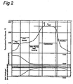
- This stage is called “pre-warming” in Fig. 2 .
- the moisture begins to evaporate from the biomass.
- the temperature of the biomass reaches the evaporation temperature, the free and loosely bound water evaporates from the biomass, while the temperature remains virtually constant.
- pre-drying in Fig. 2 .
- the biomass is dried in the dryer 3 until about 7-15% residual moisture content remains in it.
- the pre-dried biomass then leaves the dryer 3 through an outlet 7. Most of the energy of the hot gases introduced is used for drying the biomass, so its own temperature drops to 70-80°C.
- the cooled gases are removed from the dryer 3 through an outlet 8.
- the device 1 for treating biomass also comprises a torrefaction reactor 10.
- the torrefaction reactor according to the invention has an inlet 11 that is connected to the outlet 7 of the dryer 3.
- the pre-dried biomass can therefore be introduced into the torrefaction reactor 10 through the inlet 11.
- the torrefaction reactor 10 also has at least one inlet orifice 12.
- a hot gas flows through the inlet orifice 12 into the torrefaction reactor 10, so that heat transfer takes place by direct contact between the hot gas and the biomass.
- the torrefaction reactor can also be constructed for an indirect heat exchange between the hot gas and the biomass.
- Fig. 2 shows that the temperature of the biomass must first rise before torrefaction can take place. After all, the minimum temperature needed for torrefaction is about 200°C. As the temperature rises, the bound water evaporates from the biomass until the biomass is virtually free of moisture. This stage is called “post-drying and heating" in Fig. 2 . This post-drying and heating is carried out according to the invention in a drying chamber of the torrefaction reactor, which will be explained in more detail later with the aid of Fig. 3 .
- the biomass will then be torrefied (see "torrefaction" in Fig. 2 ) in a torrefying chamber of the torrefaction reactor.
- the temperature T torr can be regulated and affects the properties of the biomass fuel.
- the product quality of the torrefied biomass is reached at point A, but generally not enough combustible torrefaction gases have formed yet.
- the maximum torrefying temperature T torr is maintained beyond this point A, so that the amount of combustible torrefaction gases increases in the torrefaction reactor 10.
- the quality of the torrefied biomass is also improved here further.
- the combustible torrefaction gases leave the torrefaction reactor 10 through at least one outlet orifice 14.
- the outlet orifice 14 is connected to a combustion unit 20 with the aid of a pipe 16.
- the combustion unit 20 has an air inlet 22.
- the torrefaction gases introduced into the combustion unit 20 burn therein, which gives rise to a very hot flue gas.
- the flue gas has a temperature, for example, that lies in the range of 1000-1600°C, being e.g. 1200°C.
- the combustion unit 20 has an outlet 24 for the removal of this flue gas.
- the combustion unit 20 may also have an inlet 23 for additional fuel. The inlet 23 is desirable for example when the torrefying gases are not combustible or give rise to a flue gas that is not hot enough.
- the device I shown in Fig. 1 for treating biomass also comprises a heat exchanger 30.
- the heat exchanger 30 has an inlet 32 for hot flue gas, which inlet is connected to the outlet 24 of the combustion unit 20 with the aid of a pipe 25.
- the heat exchanger 30 has an inlet 33 for torrefaction gas.
- a fan 18 is provided in the branch line 17. Therefore, part of the torrefaction gas leaving the torrefaction reactor 10 flows into the heat exchanger 30 through the branch line 17, the fan 18 and the inlet 33.
- the flue gas entering through inlet 32 raises the temperature of the torrefaction gas to about 200-400°C. As a result of this the flue gas itself cools down to about 500-1000°C.
- the cooled flue gas then leaves the heat exchanger 30 through outlet 34, which is connected to the inlet 6 of the dryer 3.
- the heat exchanger can be either of the direct or the indirect type.
- direct heat exchange the torrefaction gas and the flue gas are in direct contact with each other.
- indirect heat exchanger the hot flue gas at a temperature of 1000-1600°C is used to heat e.g. an oil to 250-400°C, and the hot oil then heats up the torrefying gas. After that, this heated torrefaction gas flows into the torrefying chamber through the inlet orifice 12.
- the torrefied biomass is removed from the torrefaction reactor 10 through an outlet 13.
- the torrefied biomass is then conveyed to a cooler 40, where the biomass can cool down to room temperature. This is indicated by "cooling" in Fig. 2 .
- Fig. 1 shows the torrefaction reactor 10 schematically in the form of a single block diagram
- the torrefaction reactor 10 according to the invention comprises at least two reactor spaces.
- the first reactor space provides the drying chamber, while the second reactor space forms the torrefying chamber.
- the torrefaction reactor 10 according to the invention is shown in Fig. 3 in more detail.
- the torrefaction reactor 10 is essentially in the vertical position when it is in operation.
- the torrefaction reactor 10 comprises a peripheral wall 50, a bottom section 51 and a top section 52.
- the inlet 11 for introducing biomass into the torrefaction reactor 10 is located at one side of the bottom section 51.
- the bottom section 51 comprises a feed device 53 for conveying the biomass upwards within the peripheral wall 50.
- the feed device 53 is shown schematically in Fig. 3 .
- the peripheral wall 50 in the torrefaction reactor is filled with biomass during operation.
- the feed device 53 can have various designs.
- the feed device comprises two pistons and a supporting valve.
- the first piston can move through the inlet 11 to push in biomass for the second piston, which can move up and down within the peripheral wall.
- the supporting valve can move between a supporting position and a free position. When the piston has reached the end of its stroke, the supporting valve moves over to the supporting position to support the biomass within the peripheral wall.
- the second piston can then move downwards, after which the first piston can again load a quantity of biomass on it.
- the feed device can also be designed as a conveyer screw.
- the design of the feed device 53 depends on the orientation of the torrefaction reaction, which can be essentially vertical, horizontal or inclined at an angle between the two.
- the torrefaction reactor 10 is divided into a first reaction space or drying chamber 54 for the evaporation of residual moisture from the biomass, and a second reaction space or torrefying chamber 55 for torrefaction of the biomass.
- a first reaction space or drying chamber 54 for the evaporation of residual moisture from the biomass
- a second reaction space or torrefying chamber 55 for torrefaction of the biomass.
- the transition between the reaction spaces 54 and 55 is indicated by the dashed line C.
- the drying chamber 54 and the torrefying chamber 55 are therefore not enclosed chambers but form a continuous drying space 54 and torrefying space 55.
- the drying chamber 54 is therefore located between the biomass inlet 11 and the torrefying chamber 55.
- the drying chamber 54 has a number of inlet orifices 12a for the introduction of a hot drying gas.
- the drying gas introduced comes from the heat exchanger 30 (see Fig. 1 ) and has a temperature of e.g. 100-400°C.
- the drying gas and the biomass move in co-current with each other in the drying chamber 54.
- the drying gas can penetrate to the biomass at the location of the core within the peripheral wall.
- the drying gas that is introduced through the top inlet orifice 12a forms a stream of hot gas along the inside of the peripheral wall 50. Owing to this flow, the drying gas that has been introduced through the inlet orifice 12a below the first one is forced to move away from the peripheral wall 50 and is directed radially inward. This is indicated schematically by the arrows D. This ensures that not only the biomass by the peripheral wall but also the biomass in the middle is able to dry fully.
- the biomass When the biomass surpasses the level indicated by the dashed line C, the biomass is almost fully dry, i.e. the residual moisture has almost completely evaporated from the biomass.
- the moisture content of the biomass is then preferably ⁇ 3%.
- the temperature of the biomass has risen to about 200°C at the same time. Therefore, what happens above the level shown by the dashed line C is torrefaction.
- the biomass is then located in the torrefying chamber 55 for torrefying the biomass.
- the torrefying chamber 55 has inlet orifices 12b for torrefying gas, which are located in the top section 52 of the torrefaction reactor 10.
- the torrefying gas is the hot gas introduced into the torrefying chamber to torrefy the biomass.
- the torrefying gas is derived from the heat exchanger 30 (see Fig. 1 ), just like the drying gas.
- the torrefying gas flows from the inlet orifices 12b downwards through the biomass.
- the torrefying gas moves in counter-current to the biomass.
- the biomass is torrefied as it moves upward.
- the gas mixture leaving the torrefaction reactor 10 through the outlet orifices 14 will therefore contain relatively little steam according to the invention.
- the flow in the pipe 16 and the branch line 17 (see Fig. 1 ) is therefore relatively limited, which reduces the required power of the fan 18.
- the discharged combustible torrefaction gas will be hardly diluted with steam from the drying chamber 54, if at all. This has a favourable effect on the burning properties in the combustion unit 20 (see Fig. 1 ).
- the torrefaction reactor 10 has an overflow part 58. As the torrefied biomass is pushed over the edge of the overflow part 58, it overbalances along the overflow part 58 and falls into the cooling unit 40.
- the cooling unit has an inlet orifice 41 for the introduction of cooling gas. The temperature of the torrefied biomass decreases to room temperature in the cooling chamber 40. The cooled biomass leaves the cooling unit 40 through the outlet 42.
- Fig. 4 shows the temperature of the biomass, the drying gas and the torrefying gas as a function of the height z inside the torrefaction reactor (see Fig. 3 ).
- the temperature of the biomass is shown by the lowest line E, while the temperature of the drying gas and the temperature of the torrefying gas are shown by lines F and G, respectively.
- the separation between the drying chamber 54 and the torrefying chamber 55 is again shown by a dashed line C.
- Fig. 4 refers to the process according to the invention as described in the case of Fig. 3 .
- the biomass and the drying gas move in the drying chamber 54 in co-current with each other.
- the residual moisture can be eliminated from the biomass quickly and efficiently.
- the biomass and the torrefying gas introduced move in counter-current to each other. This makes it possible to control the maximum torrefying temperature accurately.
- Fig. 5 shows a second embodiment of a device for treating biomass, where the same reference numerals denote the same parts.
- the operation and construction essentially corresponds to the process and device for treating biomass as described above, and this embodiment also has the advantages mentioned above.
- the embodiment illustrated in Fig. 5 will be described below further as follows.
- the dryer used for pre-drying the biomass is not shown in Fig. 5 .
- the biomass, whether pre-dried or not, is introduced into the torrefaction reactor 10 through the inlet 11.
- the torrefaction reactor 10 is essentially vertical. Within the peripheral wall 50, the biomass moves downward under the influence of gravity. After all, the inlet 11 is located in the top section 52 of the torrefaction reactor 10, while the outlet 13 is in its bottom section 51.
- the top section of the torrefaction reactor 10 forms the drying chamber 54, while the bottom section of the torrefaction reactor 10 defines the torrefying chamber 55.
- the drying chamber 54 is located between the biomass inlet 11 and the torrefying chamber 55.
- the torrefying chamber 55 is bounded between the drying chamber 54 and the biomass outlet 13.
- the drying chamber 54 has one or more inlet orifices 12a.
- a hot drying gas flows into the drying chamber 54 of the torrefaction reactor 10 through the inlet orifices 12a, so that heat transfer takes place by direct contact between the hot drying gas and the biomass.
- the drying chamber can also be designed according to the invention for indirect heat exchange between the hot drying gas and the biomass.
- the drying gas and the biomass move in the drying chamber 54 in co-current with each other.
- Preferably a number of inlet orifices 12a are provided, one above the other, so that the drying gas can penetrate to the biomass at the location of the core (not shown in Fig. 5 ).
- the hot drying gas raises the temperature of the biomass in the drying chamber 54 and evaporates the bound water from the biomass until the biomass is almost free of moisture. This stage is indicated in Fig. 2 by "post-drying and heating".
- the hot drying gas is cooled in the process.
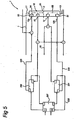
- the cooled drying gas is then introduced into a first heat exchanger 200.
- the first heat exchanger 200 heats the drying gas, and this heated drying gas is then again introduced into the drying chamber 54 through the inlet orifices 12a. This forms a first circuit 203, in which the drying gas circulates.
- the biomass descends from the drying chamber 54 into the torrefying chamber 55 of the torrefaction reactor, i.e. the biomass surpasses the level indicated by the dashed line C.
- the biomass is then almost completely dry, i.e. the residual moisture has been almost fully evaporated from the biomass.
- the biomass now contains e.g. ⁇ 3% of moisture.
- the temperature of the biomass will have risen to about 200°C at the same time.
- a hot torrefying gas is passed into the torrefying chamber 55 through the inlet orifices 12b.
- the torrefying gas is the hot gas that is introduced into the torrefying chamber 55 to torrefy the biomass.
- the torrefying gas moves from the inlet orifices 12b upward through the biomass.
- the torrefying gas and the biomass move in counter-current to each other.
- the biomass will be torrefied as it moves downward.
- Combustible torrefaction gases are formed when the biomass is heated to the maximum torrefying temperature T torr in the second reaction space 55.
- the amount of combustible torrefaction gas increases by maintaining this temperature for some time.
- the torrefying gas introduced and the torrefaction gases formed leave the torrefying chamber 55 through the outlet orifices 14.
- the outlet orifices 14 are connected to the pipe 16 with the aid of a branch line, and pipe 16 is connected to a combustion unit 20 (not shown in Fig. 5 ).
- the outlet orifices 14 are likewise connected to a second heat exchanger 201, and part of the torrefaction gas formed is passed into the second heat exchanger 201.
- the heat exchanger 201 heats up the torrefaction gas, and the heated torrefaction gas is introduced into the torrefying chamber 55 through the inlet orifices 12b.
- the torrefaction gas formed is used as the torrefying gas. This gas is recirculated in a second circuit 205.
- the temperature profile shown in Fig. 4 also applies to the embodiment illustrated in Fig. 5 .
- the biomass and the drying gas move in the drying chamber 54 in co-current with each other. As a result the residual moisture can be eliminated from the biomass quickly and efficiently.
- the biomass and the torrefying gas supplied move in counter-current to each other. This makes it possible to control the maximum torrefying temperature accurately.
- the heating of the drying gas and the torrefying gas in the respective heat exchangers 200 and 201 can be carried out with the aid of a third circuit 209, which comprises a heating unit 207.
- the heating unit 207 can be e.g. an oil boiler, in which case hot oil is circulated in the third circuit 209, including the heat exchangers 200 and 201. This is made possible by the use of a co-current flow in the drying chamber 54 and a counter-current flow in the torrefying chamber 55, in which case the temperatures of the drying gas and the torrefying gas remain relatively low.
- the torrefied biomass is removed from the torrefaction reactor 10 through the outlet 13.
- the torrefied biomass is then transferred to a cooler 40 (not shown in Fig. 5 ), where the biomass can be cooled down to room temperature. This is indicated in Fig. 2 by "cooling".
- the drying chamber 54 and the torrefying chamber 55 can be made as separate entities, connected to each other by a pipe.
- the drying chamber 54 is then housed in a separate residual-moisture dryer, while the torrefying chamber 55 is incorporated in the torrefaction reactor 10.
- the residual-moisture dryer in the system illustrated in Fig. 1 is inserted between the preliminary dryer 3 and the torrefaction reactor 10.
Landscapes
- Chemical & Material Sciences (AREA)
- Oil, Petroleum & Natural Gas (AREA)
- Organic Chemistry (AREA)
- Engineering & Computer Science (AREA)
- Thermal Sciences (AREA)
- Combustion & Propulsion (AREA)
- Physics & Mathematics (AREA)
- Materials Engineering (AREA)
- Life Sciences & Earth Sciences (AREA)
- Biodiversity & Conservation Biology (AREA)
- Forests & Forestry (AREA)
- Wood Science & Technology (AREA)
- Agronomy & Crop Science (AREA)
- Ecology (AREA)
- Drying Of Solid Materials (AREA)
- Processing Of Solid Wastes (AREA)
- Coke Industry (AREA)
Description
- The invention relates to a process for treating a material, such as biomass or waste, comprising:
- the provision of a material that contains an amount of residual moisture,
- the provision of a torrefaction reactor,
- the heating of the material in the torrefaction reactor to a torrefying temperature in a low-oxygen atmosphere in the torrefaction reactor, wherein the material is converted into a torrefied material.
-
DE 3211590 relates to a process for torrefying a material, such as biomass. The material is supplied from above to a reactor 1 (page 9, second paragraph; seefigure 2 ). The reactor 1 is provided with an inner tube 3, which extends over the entire height of the reactor 1 and which is closed at its upper and lower ends. The reactor 1 is divided at 13 into an upper drying zone and a lower torrefying zone. A hot gas is introduced into the inner tube 3 via the supply line 5. The gas flows transversely 8 ("quer") through the material in the processing chamber 2 (see page 9, last paragraph). The gas is withdrawn into the annularouter chamber 11 via covered openings 9. -
FR 2624876 drying chamber 2 and a torrefying chamber 3 (seefigure 1 ). The flow of the gas in the torrefying chamber 3 is in counter-current to the material (page 12, lines 12-17). According topage 10, line 32 -page 11,line 2 it is advantageous for the flow of the gas in thedrying chamber 2 to be in counter-current to the material as well.DE3041627 discloses a similar set-up as the disclosure ofFR2624876 - The term "material" or "raw material" is used here to denote various kinds of materials or raw materials. In this patent application the term "material" or "raw material" refers not only to biomass or waste, but also any organic material. Because the material contains carbon it is generally combustible. The material can be derived e.g. from (agricultural) residues or waste.
- Such a process is known. In the untreated state, many materials are relatively wet. The material generally contains free (unbound) and (loosely) bound water. The bound or loosely bound water is absorbed by the natural raw material itself. For example, biomass of plant origin, such as prunings and mown grass, contains a considerable amount of moisture by nature.
- Furthermore, biomass can be very wet as a result of washing it or subjecting it to an alternative water treatment in order to reduce the salt content of the biomass. The removal of salts is desirable, because salts in biomass used as a fuel lead more quickly to corrosion formation in the combustion chamber of a power station. These salts also reduce the quality of the ash produced during combustion of the biomass fuel, which hampers the utilization of this ash. Water-soluble salts can in particular be washed out of biomass of plant origin, such as straw.
- The raw material usually has a moisture content of 5-15%, i.e. an amount of residual moisture is contained in the material. This material with the residual moisture is introduced into the torrefaction reactor. Torrefaction is a thermochemical treatment method for material. In this method the material is heated in a low-oxygen (with substoichiometric quantities of oxygen) or oxygen-free gaseous atmosphere, usually under atmospheric pressure to a temperature of 200-320°C. The lack of oxygen prevents the material from burning. Instead the material is torrefied, which leads to loss of mass because of the elimination of gases. This loss of mass generally amounts to about 30%, while the energy value is only reduced by 10%. The fuel produced by torrefaction therefore has a higher calorific value.
- Torrefaction also causes chemical changes to the structure of the material. The material loses its mechanical strength and elasticity, so it is much easier to grind. Furthermore, torrefied material is hydrophobic, and it therefore stays dry and is insensitive to atmospheric humidity. The risk of rotting and overheating is very small when the material which has been produced by torrefaction is stored.
- The temperature of the material is raised in the torrefaction reactor. Before torrefaction of the material can take place, the residual moisture must, however, first be evaporated from the material. The material is virtually completely dried in the torrefaction reactor by evaporating the residual moisture. The actual torrefaction of the material only takes place after the residual moisture has been evaporated. Torrefaction begins as soon as the temperature of the material then exceeds about 200°C. The torrefying temperature is, however, generally higher, being about 250°C.
- A considerable amount of steam is generated in the torrefaction reactor when the residual moisture is evaporated in the torrefaction reactor. This can lead to a relatively fast-moving gas stream flowing in the reactor, which increases the pressure drop over the reactor. Furthermore, the energy needed for evaporating the residual moisture is much greater than the energy required for torrefaction. In particular, in a torrefaction reactor based on direct contact between the gas and the material, a relatively large amount of hot gas must be introduced into the torrefaction reactor at a high inlet temperature, which further increases the amount of gas that has to pass through the torrefaction reactor. This hampers the implementation of the method of treatment.
- An object of the invention is to provide an improved process for treating material.
- This object is achieved according to the invention by the material with the residual moisture contained in it being essentially fully dried in a drying chamber by evaporation of the residual moisture, and the torrefaction of the dried material being essentially carried out in a torrefying chamber of the torrefaction reactor, and the material being conveyed through the torrefaction reactor in a transport direction, and the drying of the material in the drying chamber being carried out by introducing into it a hot drying gas that flows through the drying chamber in co-current with the material, and the torrefaction of the material in the torrefying chamber of the torrefaction reactor being carried out by introducing into it a hot torrefying gas that flows through the torrefying chamber of the torrefaction reactor in counter-current to the material.
- According to the invention, the material is dried in the drying chamber, after which the material is torrefied in the torrefying chamber. The drying chamber and the torrefying chamber form two separate spaces here. Unlike in the known process, the evaporation of residual moisture from the material and the torrefaction of the material according to the invention therefore form two separate stages, each of which can be optimized.
- The material is almost fully dried in the drying chamber, which requires a relatively large amount of energy. The evaporation of residual moisture from the material is efficient, because the material and the hot gas move in co-current with each other. The drying chamber is designed specifically for the drying of the material.
- When a hot gas is introduced, which is e.g. in direct contact with the material, the temperature of the material in the torrefaction reactor rises to a torrefying temperature. Since this hot gas flows in counter-current to the material, the temperature of the hot gas "follows" the temperature of the material. The temperature of the material and the temperature of the hot gas both increase in the transport direction of the material. The inlet temperature of the hot gas then needs only be somewhat above the temperature of the material at the outlet. There is only a very small risk of "hot spots" developing in the dry material, or of uncontrolled torrefaction or pyrolysis taking place. Only a relatively small amount of energy needs to be introduced into the torrefying chamber, which allows for an improved dosing and/or fine tuning of the energy input. As a result, the torrefying temperature in the torrefying chamber can be set and controlled accurately.
- A further advantage of the invention is that the required temperatures of the hot gases introduced - drying gas and torrefying gas - are relatively low. This facilitates the production of these hot gases. For example, the temperature of the hot gas introduced into the torrefying chamber is in the range of 200-400°C, being e.g. about 300°C. Controlled torrefaction can be carried out in the torrefying chamber at such a temperature. In addition the temperature of the hot gas introduced into the drying chamber can be in the range of 150-600°C, being e.g. about 350°C. This temperature is particularly suitable for the almost complete drying of the material, such as to a moisture content of ≤ 3%. These temperatures are sufficiently low for the production using e.g. a thermal oil.
- The torrefaction reactor may comprise the drying chamber and the torrefying chamber. When the drying chamber and the torrefying chamber are accommodated in the torrefaction reactor, the drying chamber and the torrefying chamber form two reaction spaces of the torrefaction reactor. The drying of the material by evaporation of the residual moisture is essentially carried out in the first reaction space, i.e. the drying chamber, and the torrefaction of the material is essentially carried out in the second reaction space, i.e. the torrefying chamber. The material is in fact almost completely dried here by evaporation of the residual moisture in the torrefaction reactor, but the process in the torrefaction reactor is separated according to the invention into two stages, each of which can be optimized.
- However, it is also possible according to the invention to house the drying chamber in a residual-moisture dryer, and to house the torrefying chamber in the torrefaction reactor. In this case, the residual-moisture dryer forms a separate device, which is housed separately from the torrefaction reactor. The residual-moisure dryer can be so designed as to ensure the efficient evaporation of the residual moisture from the material. The residual-moisture dryer is connected with the torrefaction reactor for the transfer of the almost fully dried material from the residual-moisture dryer into the torrefying chamber.
- It is possible according to the invention for the drying gas, after it has moved in co-current with the material and has thus been cooled to leave the drying chamber and to be introduced into a first heat exchanger, which heats up this drying gas, after which the drying gas heated up by the first heat exchanger is introduced into the drying chamber, and the torrefying gas after it has moved in counter-current to the material and has thus been cooled down leaving the torrefying chamber and being introduced into a second heat exchanger, which heats up this torrefying gas, after which the torrefying gas that has been heated up by the second heat exchanger is introduced into the torrefying chamber. In this case, the drying gas circulates in a first circuit, while the torrefying gas circulates in a second circuit. By using two circuits, each with its own heat exchanger, it is possible to ensure an efficient energy recovery from the drying gas and the torrefying gas.
- In particular, the provision of the material by the process according to the invention comprises introducing a relatively wet raw material into a dryer, and heating the material in the dryer to evaporate moisture from the material until the amount of residual moisture stays in it, the material that has been dried in the dryer being introduced into the drying chamber. The relatively wet material has a moisture content of e.g. more than 15%. The relatively wet material can then be thermally dried in a dryer, such as.a rotating-drum dryer before being introduced into the drying chamber of the torrefaction reactor or the residual-moisture dryer. As the material is warmed in the dryer, the temperature rises sufficiently to evaporate moisture from the material. The material is not fully dried in the dryer, i.e. an amount of residual moisture is left in the material. The residual moisture is mainly formed by bound water in the material. In practice, energy is introduced into the dryer until the moisture content of the material is about 10-15%. The biomass is then 85-90% dry. Reducing the moisture content in the dryer further would reduce the yield of the whole treatment method. For example, the dryer is not suitable for drying the material further in an economically efficient manner.
- Incidentally, material with a moisture content higher than 15% can of course also be fed into the torrefaction reactor without preliminary drying or pre-drying in a separate dryer. For example, straw generally has a moisture content of about 20%. This straw can be directly fed into the torrefaction reactor according to the invention without preliminary drying. The drying of that straw then takes place completely in the drying chamber of the torrefaction reactor according to the invention. Conversely, it may sometimes be desirable first to pre-dry in the dryer material that only contains a relatively small amount of moisture, such as 5% or less.
- The material according to the invention should preferably contain solid particles that are passed through the torrefaction reactor in the form of a packed moving bed. In this case the torrefaction reactor is operated on the principle of moving-bed technology.
- The invention also relates to a device for treating material, comprising a torrefaction reactor, to which material can be fed which contains an amount of residual moisture, which torrefaction reactor is provided with an inlet for introducing this material into the torrefaction reactor, heating means for heating the material in the torrefaction reactor to a torrefying temperature, air-treating means for creating a low-oxygen environment (with substoichiometric quantities of oxygen) in the torrefaction reactor wherein the material can be converted into torrefied material during operation, and an outlet for removing torrefied material. More in particular, the present invention relates to a device for treating material as defined in claim 9.
- The drying gas and the torrefying gas are both hot gases. The hot drying gas is intended for evaporating residual moisture in the drying chamber, while the hot torrefying gas is intended for heating the almost completely dry material in the torrefying chamber to the required torrefying temperature. Combustible torrefaction gases are formed during the torrefaction process in the torrefying chamber and can be removed through the outlet orifice.
- During operation, the material is conveyed through the torrefaction reactor in a transport direction. The material is dried in the drying chamber by the introduction of a hot drying gas into it through one or more inlet orifices in the drying chamber. The hot drying gas flows through the drying chamber in co-current with the material. The torrefaction of the material in the torrefying chamber of the torrefaction reactor is carried out by introducing into it a hot torrefying gas through one or more inlet orifices in the torrefying chamber. The hot torrefying gas flows through the torrefying chamber of the torrefaction reactor in counter-current to the material. The drying gas and the torrefying gas flow towards each other from opposite ends of the torrefaction reactor. These gases meet each other at the outlet orifices located between the drying gas inlet orifices and the torrefying gas inlet orifices. This ensures a gas separation between the drying chamber and the torrefying chamber. The drying chamber and torrefying chamber are located at opposite ends of the gas separation - the gas separation delimits the drying chamber and torrefying chamber with respect to each other. Unlike in the prior art, where the material can be almost fully dried by evaporation of the residual moisture in the torrefaction reactor, the process in the device according to the invention can be split into two stages which can be set in an optimum manner.
- When the drying chamber and the torrefying chamber are housed in the torrefaction reactor, the drying chamber and the torrefying chamber form two separate spaces in the same torrefaction reactor. In an alternative embodiment the drying chamber is located e.g. in a residual-moisture dryer, and the torrefying chamber is located in the torrefaction reactor. In this case, the residual-moisture dryer forms a separate entity, which is housed separately with respect to the torrefaction reactor.
- It is possible according to the invention to provide a dryer to which a relatively wet material can be supplied, which dryer has heating means to warm this material in order to evaporate moisture from the material until the amount of residual moisture stays in it, and the material dried in the dryer being able to be fed into the drying chamber of the torrefaction reactor. This makes the device according to the invention suitable for handling relatively wet material, for example material with a moisture content of about 15%, 25% or more. The relatively wet material can be thermally pre-dried in the dryer before it is fed into the torrefying chamber.
- The device according to the invention can therefore comprise two dryers and a torrefying chamber. The first drier forms a preliminary dryer that is used to reduce the moisture content to e.g. about 5-15%. The second dryer is formed by the drying chamber in the torrefaction reactor or by the residual-moisture dryer as described above.
- In one embodiment of the invention, the torrefaction reactor is bounded by a peripheral wall, the drying chamber and the torrefying, chamber extending as a continuation of each other within the peripheral wall. When viewed in the direction of flow of the material, the drying chamber is located between the inlet for material and the torrefying chamber, and the torrefying chamber is located between the drying chamber and the outlet for torrefied material.
- In one embodiment of the invention, the torrefaction reactor is mounted in the upright position, a number of inlet orifices being provided in the peripheral wall, one above the other, for drying gas. This torrefaction reactor can be e.g. vertical or it can be erected at an angle. Since these orifices are distributed around the periphery of the peripheral wall, the gas can penetrate to the material which is located centrally within the peripheral wall. The material is given sufficient opportunity for drying over its entire cross section within the peripheral wall.
- The material can move from the top downwards within the peripheral wall under the influence of gravity. However, it is also possible for the material to flow through the torrefaction reactor from below upwards. For this purpose a feed device is provided, for example, such as a screw member or a piston which can move up and down within the peripheral wall. The feed device can be located outside the hot peripheral wall of the torrefaction reactor. The thermal load of the feed device is thereby reduced.
- In one embodiment of the invention, the outlet is connected to a cooling chamber and the torrefied material can be introduced from the torrefying chamber into the cooling chamber. For example, the feed device pushes the material within the peripheral wall of the torrefaction reactor upwards until the material reaches an overflow part. The torrefied material overbalances along the edge of the overflow part and drops beyond it into the cooling chamber. The cooling chamber is generally provided with inlet orifices for cooling gas. The cooling gas cools the torrefied material.
- The invention will now be further explained with reference to an exemplary embodiment illustrated in the figures.
- Fig. 1
- shows a schematic process flow diagram for the process of treating biomass according to the invention.
- Fig. 2
- shows a graph in which the temperature of the biomass, the moisture content of the biomass, and the energy introduced into the process (on a cumulative basis) are plotted against time.
- Fig. 3
- shows a view in cross section of a torrefaction reactor according to the invention.
- Fig. 4
- shows a graph in which the temperature of the drying gas, the torrefying gas, and the biomass are plotted against the vertical distance in the torrefaction reactor.
- Fig. 5
- shows a schematic process diagram in the case of a second embodiment of a process for treating biomass according to the invention.
- The design of the process and device according to the invention will be described below with the aid of the figures for treating biomass. However, the invention is not limited to biomass but can be applied to all kinds of material. For example, various low-mobility materials, such as non-biodegradable waste, can be treated according to the invention.
- The device for treating biomass according to the invention is indicated in its entirety by 1. The device for treating biomass I comprises in this embodiment a dryer 3, acting as a preliminary dryer. The dryer 3 has an inlet 5 for the introduction of wet biomass into the dryer 3. The dryer 3 also has an inlet 6 for hot gas, which is at a temperature of e.g. about 800°C.
- The hot gas introduced raises the temperature of the biomass in the dryer 3 but does not reduce the moisture content in the biomass at first. This stage is called "pre-warming" in
Fig. 2 . As the temperature rises, the moisture begins to evaporate from the biomass. When the temperature of the biomass reaches the evaporation temperature, the free and loosely bound water evaporates from the biomass, while the temperature remains virtually constant. This stage is called "pre-drying" inFig. 2 . The biomass is dried in the dryer 3 until about 7-15% residual moisture content remains in it. The pre-dried biomass then leaves the dryer 3 through an outlet 7. Most of the energy of the hot gases introduced is used for drying the biomass, so its own temperature drops to 70-80°C. The cooled gases are removed from the dryer 3 through an outlet 8. - The device 1 for treating biomass also comprises a
torrefaction reactor 10. The torrefaction reactor according to the invention has aninlet 11 that is connected to the outlet 7 of the dryer 3. The pre-dried biomass can therefore be introduced into thetorrefaction reactor 10 through theinlet 11. Thetorrefaction reactor 10 also has at least oneinlet orifice 12. A hot gas flows through theinlet orifice 12 into thetorrefaction reactor 10, so that heat transfer takes place by direct contact between the hot gas and the biomass. However, according to the invention, the torrefaction reactor can also be constructed for an indirect heat exchange between the hot gas and the biomass. -
Fig. 2 shows that the temperature of the biomass must first rise before torrefaction can take place. After all, the minimum temperature needed for torrefaction is about 200°C. As the temperature rises, the bound water evaporates from the biomass until the biomass is virtually free of moisture. This stage is called "post-drying and heating" inFig. 2 . This post-drying and heating is carried out according to the invention in a drying chamber of the torrefaction reactor, which will be explained in more detail later with the aid ofFig. 3 . - The biomass will then be torrefied (see "torrefaction" in
Fig. 2 ) in a torrefying chamber of the torrefaction reactor. During the torrefaction process, the temperature rises from about 200°C until a maximum torrefying temperature Ttorr is reached at point A inFig. 2 . The temperature Ttorr can be regulated and affects the properties of the biomass fuel. The product quality of the torrefied biomass is reached at point A, but generally not enough combustible torrefaction gases have formed yet. The maximum torrefying temperature Ttorr is maintained beyond this point A, so that the amount of combustible torrefaction gases increases in thetorrefaction reactor 10. The quality of the torrefied biomass is also improved here further. The combustible torrefaction gases leave thetorrefaction reactor 10 through at least oneoutlet orifice 14. - The
outlet orifice 14 is connected to acombustion unit 20 with the aid of apipe 16. Thecombustion unit 20 has an air inlet 22. The torrefaction gases introduced into thecombustion unit 20 burn therein, which gives rise to a very hot flue gas. The flue gas has a temperature, for example, that lies in the range of 1000-1600°C, being e.g. 1200°C. Thecombustion unit 20 has anoutlet 24 for the removal of this flue gas. Thecombustion unit 20 may also have aninlet 23 for additional fuel. Theinlet 23 is desirable for example when the torrefying gases are not combustible or give rise to a flue gas that is not hot enough. - The device I shown in
Fig. 1 for treating biomass also comprises aheat exchanger 30. Theheat exchanger 30 has aninlet 32 for hot flue gas, which inlet is connected to theoutlet 24 of thecombustion unit 20 with the aid of apipe 25. In addition, theheat exchanger 30 has aninlet 33 for torrefaction gas. From thepipe 16 that connects thetorrefaction reactor 10 to thecombustion chamber 20, there is a branch line 17 running to theinlet 33 of theheat exchanger 30. Afan 18 is provided in the branch line 17. Therefore, part of the torrefaction gas leaving thetorrefaction reactor 10 flows into theheat exchanger 30 through the branch line 17, thefan 18 and theinlet 33. The flue gas entering throughinlet 32 raises the temperature of the torrefaction gas to about 200-400°C. As a result of this the flue gas itself cools down to about 500-1000°C. The cooled flue gas then leaves theheat exchanger 30 through outlet 34, which is connected to the inlet 6 of the dryer 3. - The heat exchanger can be either of the direct or the indirect type. In the case of direct heat exchange, the torrefaction gas and the flue gas are in direct contact with each other. In an indirect heat exchanger, the hot flue gas at a temperature of 1000-1600°C is used to heat e.g. an oil to 250-400°C, and the hot oil then heats up the torrefying gas. After that, this heated torrefaction gas flows into the torrefying chamber through the
inlet orifice 12. - The torrefied biomass is removed from the
torrefaction reactor 10 through anoutlet 13. The torrefied biomass is then conveyed to a cooler 40, where the biomass can cool down to room temperature. This is indicated by "cooling" inFig. 2 . - Although
Fig. 1 shows thetorrefaction reactor 10 schematically in the form of a single block diagram, thetorrefaction reactor 10 according to the invention comprises at least two reactor spaces. The first reactor space provides the drying chamber, while the second reactor space forms the torrefying chamber. Thetorrefaction reactor 10 according to the invention is shown inFig. 3 in more detail. - The
torrefaction reactor 10 is essentially in the vertical position when it is in operation. Thetorrefaction reactor 10 comprises aperipheral wall 50, abottom section 51 and atop section 52. Theinlet 11 for introducing biomass into thetorrefaction reactor 10 is located at one side of thebottom section 51. Thebottom section 51 comprises afeed device 53 for conveying the biomass upwards within theperipheral wall 50. Thefeed device 53 is shown schematically inFig. 3 . Theperipheral wall 50 in the torrefaction reactor is filled with biomass during operation. - The
feed device 53 can have various designs. For example, the feed device comprises two pistons and a supporting valve. The first piston can move through theinlet 11 to push in biomass for the second piston, which can move up and down within the peripheral wall. The supporting valve can move between a supporting position and a free position. When the piston has reached the end of its stroke, the supporting valve moves over to the supporting position to support the biomass within the peripheral wall. The second piston can then move downwards, after which the first piston can again load a quantity of biomass on it. However, the feed device can also be designed as a conveyer screw. The design of thefeed device 53 depends on the orientation of the torrefaction reaction, which can be essentially vertical, horizontal or inclined at an angle between the two. - Within the
peripheral wall 50, thetorrefaction reactor 10 is divided into a first reaction space or dryingchamber 54 for the evaporation of residual moisture from the biomass, and a second reaction space or torrefyingchamber 55 for torrefaction of the biomass. In this exemplary embodiment, there is no physical separation between the dryingchamber 54 and the torrefyingchamber 55 and thereaction spaces reaction spaces chamber 54 and the torrefyingchamber 55 are therefore not enclosed chambers but form acontinuous drying space 54 andtorrefying space 55. - The drying
chamber 54 is therefore located between thebiomass inlet 11 and the torrefyingchamber 55. The dryingchamber 54 has a number ofinlet orifices 12a for the introduction of a hot drying gas. The drying gas introduced comes from the heat exchanger 30 (seeFig. 1 ) and has a temperature of e.g. 100-400°C. The drying gas and the biomass move in co-current with each other in the dryingchamber 54. - Since a number of
inlet orifices 12a are placed one over the other the drying gas can penetrate to the biomass at the location of the core within the peripheral wall. The drying gas that is introduced through thetop inlet orifice 12a forms a stream of hot gas along the inside of theperipheral wall 50. Owing to this flow, the drying gas that has been introduced through theinlet orifice 12a below the first one is forced to move away from theperipheral wall 50 and is directed radially inward. This is indicated schematically by the arrows D. This ensures that not only the biomass by the peripheral wall but also the biomass in the middle is able to dry fully. - Steam is generated during the drying of the biomass in the drying
chamber 54. Part of this steam and the drying gas cooled by evaporation leaves thetorrefaction reactor 10 throughoutlet orifices 15, located sideways in theperipheral wall 50. The steam produced is preferably largely passed into the torrefyingchamber 55 of thetorrefaction reactor 10, because the steam generally contains a considerable amount of organic compounds. - When the biomass surpasses the level indicated by the dashed line C, the biomass is almost fully dry, i.e. the residual moisture has almost completely evaporated from the biomass. The moisture content of the biomass is then preferably ≤ 3%. The temperature of the biomass has risen to about 200°C at the same time. Therefore, what happens above the level shown by the dashed line C is torrefaction. The biomass is then located in the torrefying
chamber 55 for torrefying the biomass. - The torrefying
chamber 55 hasinlet orifices 12b for torrefying gas, which are located in thetop section 52 of thetorrefaction reactor 10. The torrefying gas is the hot gas introduced into the torrefying chamber to torrefy the biomass. The torrefying gas is derived from the heat exchanger 30 (seeFig. 1 ), just like the drying gas. The torrefying gas flows from the inlet orifices 12b downwards through the biomass. The torrefying gas moves in counter-current to the biomass. In thesecond reaction space 55, the biomass is torrefied as it moves upward. As the biomass is heated to the maximum torrefying temperature Ttorr, combustible torrefaction gases are formed in thesecond reaction space 55. The amount of combustible torrefaction gas increases by maintaining this temperature for some time. The torrefying gas introduced and the torrefaction gases formed leave thesecond reaction space 55 throughoutlet orifices 14. - The gas mixture leaving the
torrefaction reactor 10 through the outlet orifices 14 will therefore contain relatively little steam according to the invention. The flow in thepipe 16 and the branch line 17 (seeFig. 1 ) is therefore relatively limited, which reduces the required power of thefan 18. Furthermore, the discharged combustible torrefaction gas will be hardly diluted with steam from the dryingchamber 54, if at all. This has a favourable effect on the burning properties in the combustion unit 20 (seeFig. 1 ). - The
torrefaction reactor 10 has anoverflow part 58. As the torrefied biomass is pushed over the edge of theoverflow part 58, it overbalances along theoverflow part 58 and falls into the coolingunit 40. The cooling unit has aninlet orifice 41 for the introduction of cooling gas. The temperature of the torrefied biomass decreases to room temperature in the coolingchamber 40. The cooled biomass leaves the coolingunit 40 through the outlet 42. -
Fig. 4 shows the temperature of the biomass, the drying gas and the torrefying gas as a function of the height z inside the torrefaction reactor (seeFig. 3 ). The temperature of the biomass is shown by the lowest line E, while the temperature of the drying gas and the temperature of the torrefying gas are shown by lines F and G, respectively. The separation between the dryingchamber 54 and the torrefyingchamber 55 is again shown by a dashed line C. -
Fig. 4 refers to the process according to the invention as described in the case ofFig. 3 . The biomass and the drying gas move in the dryingchamber 54 in co-current with each other. As a result, the residual moisture can be eliminated from the biomass quickly and efficiently. In the torrefyingchamber 55, the biomass and the torrefying gas introduced move in counter-current to each other. This makes it possible to control the maximum torrefying temperature accurately. -
Fig. 5 shows a second embodiment of a device for treating biomass, where the same reference numerals denote the same parts. The operation and construction essentially corresponds to the process and device for treating biomass as described above, and this embodiment also has the advantages mentioned above. The embodiment illustrated inFig. 5 will be described below further as follows. - The dryer used for pre-drying the biomass is not shown in
Fig. 5 . The biomass, whether pre-dried or not, is introduced into thetorrefaction reactor 10 through theinlet 11. Thetorrefaction reactor 10 is essentially vertical. Within theperipheral wall 50, the biomass moves downward under the influence of gravity. After all, theinlet 11 is located in thetop section 52 of thetorrefaction reactor 10, while theoutlet 13 is in itsbottom section 51. - The top section of the
torrefaction reactor 10 forms the dryingchamber 54, while the bottom section of thetorrefaction reactor 10 defines the torrefyingchamber 55. The dryingchamber 54 is located between thebiomass inlet 11 and the torrefyingchamber 55. The torrefyingchamber 55 is bounded between the dryingchamber 54 and thebiomass outlet 13. - The drying
chamber 54 has one ormore inlet orifices 12a. A hot drying gas flows into the dryingchamber 54 of thetorrefaction reactor 10 through theinlet orifices 12a, so that heat transfer takes place by direct contact between the hot drying gas and the biomass. However, the drying chamber can also be designed according to the invention for indirect heat exchange between the hot drying gas and the biomass. The drying gas and the biomass move in the dryingchamber 54 in co-current with each other. Preferably a number ofinlet orifices 12a are provided, one above the other, so that the drying gas can penetrate to the biomass at the location of the core (not shown inFig. 5 ). - The hot drying gas raises the temperature of the biomass in the drying
chamber 54 and evaporates the bound water from the biomass until the biomass is almost free of moisture. This stage is indicated inFig. 2 by "post-drying and heating". The hot drying gas is cooled in the process. The cooled drying gas, and possibly the gas and/or vapour formed in the evaporation of residual moisture, leave the dryingchamber 54 through the outlet orifices 15. The cooled drying gas is then introduced into afirst heat exchanger 200. Thefirst heat exchanger 200 heats the drying gas, and this heated drying gas is then again introduced into the dryingchamber 54 through theinlet orifices 12a. This forms afirst circuit 203, in which the drying gas circulates. - The biomass descends from the drying
chamber 54 into the torrefyingchamber 55 of the torrefaction reactor, i.e. the biomass surpasses the level indicated by the dashed line C. The biomass is then almost completely dry, i.e. the residual moisture has been almost fully evaporated from the biomass. The biomass now contains e.g. ≤ 3% of moisture. The temperature of the biomass will have risen to about 200°C at the same time. - A hot torrefying gas is passed into the torrefying
chamber 55 through theinlet orifices 12b. The torrefying gas is the hot gas that is introduced into the torrefyingchamber 55 to torrefy the biomass. The torrefying gas moves from the inlet orifices 12b upward through the biomass. The torrefying gas and the biomass move in counter-current to each other. In thesecond reaction space 55, i.e. below the level indicated by the dashed line C, the biomass will be torrefied as it moves downward. - Combustible torrefaction gases are formed when the biomass is heated to the maximum torrefying temperature Ttorr in the
second reaction space 55. The amount of combustible torrefaction gas increases by maintaining this temperature for some time. The torrefying gas introduced and the torrefaction gases formed leave the torrefyingchamber 55 through the outlet orifices 14. - The outlet orifices 14 are connected to the
pipe 16 with the aid of a branch line, andpipe 16 is connected to a combustion unit 20 (not shown inFig. 5 ). The outlet orifices 14 are likewise connected to asecond heat exchanger 201, and part of the torrefaction gas formed is passed into thesecond heat exchanger 201. Theheat exchanger 201 heats up the torrefaction gas, and the heated torrefaction gas is introduced into the torrefyingchamber 55 through theinlet orifices 12b. In this exemplary embodiment, the torrefaction gas formed is used as the torrefying gas. This gas is recirculated in asecond circuit 205. - The temperature profile shown in
Fig. 4 also applies to the embodiment illustrated inFig. 5 . The biomass and the drying gas move in the dryingchamber 54 in co-current with each other. As a result the residual moisture can be eliminated from the biomass quickly and efficiently. In the torrefyingchamber 55 the biomass and the torrefying gas supplied move in counter-current to each other. This makes it possible to control the maximum torrefying temperature accurately. - The heating of the drying gas and the torrefying gas in the
respective heat exchangers third circuit 209, which comprises aheating unit 207. Theheating unit 207 can be e.g. an oil boiler, in which case hot oil is circulated in thethird circuit 209, including theheat exchangers chamber 54 and a counter-current flow in the torrefyingchamber 55, in which case the temperatures of the drying gas and the torrefying gas remain relatively low. - The torrefied biomass is removed from the
torrefaction reactor 10 through theoutlet 13. The torrefied biomass is then transferred to a cooler 40 (not shown inFig. 5 ), where the biomass can be cooled down to room temperature. This is indicated inFig. 2 by "cooling". - The invention is of course not restricted to the embodiments described above. On the basis of known processes, for example, the expert will be able to introduce various modifications within the scope of the invention. For example, the drying
chamber 54 and the torrefyingchamber 55 can be made as separate entities, connected to each other by a pipe. The dryingchamber 54 is then housed in a separate residual-moisture dryer, while the torrefyingchamber 55 is incorporated in thetorrefaction reactor 10. In this case, the residual-moisture dryer in the system illustrated inFig. 1 is inserted between the preliminary dryer 3 and thetorrefaction reactor 10. There is then also a physical separation between the dryingchamber 54 and the torrefyingchamber 55, unlike in the embodiment shown inFig. 3 .
Claims (15)
- Process for treating a material, such as biomass or waste, comprising:- the provision of a material that contains an amount of residual moisture,- the provision of a torrefaction reactor (10),- the heating of the material in the torrefaction reactor (10) to a torrefying temperature in a low-oxygen atmosphere in the torrefaction reactor (10), wherein the material is converted into a torrefied material,characterized in that the material with the residual moisture contained in it is essentially fully dried in a drying chamber (54) by evaporation of the residual moisture, and the torrefaction of the dried material is essentially carried out in a torrefying chamber (55) of the torrefaction reactor (10), and the material is conveyed through the torrefaction reactor (10) in a transport direction (B), and the drying of the material in the drying chamber (54) is carried out by introducing into it a hot drying gas that flows through the drying chamber (54) in co-current with the material, and the torrefaction of the material in the torrefying chamber (55) of the torrefaction reactor is carried out by introducing into it a hot torrefying gas that flows through the torrefying chamber (55) of the torrefaction reactor (10) in counter-current to the material.
- Process according to Claim 1, in which the torrefaction reactor (10) comprises the drying chamber (54) and the torrefying chamber (55).
- Process according to Claim 1, in which the drying chamber is housed in a residual-moisture dryer, and the torrefying chamber is housed in the torrefaction reactor.
- Process according to any one of the preceding claims, in which the material contains solid particles that move through the torrefaction reactor (10) in the form of a packed moving bed.
- Process according to any one of the preceding claims, in which the drying gas after it has moved in co-current with the material and has thus been cooled leaves the drying chamber and is introduced into a first heat exchanger, which heats up this drying gas, after which the drying gas heated up by the first heat exchanger is introduced into the drying chamber (54), and the torrefying gas, after it has moved in counter-current to the material and has thus been cooled down leaves the torrefying chamber and is introduced into a second heat exchanger, which heats up this torrefying gas, after which the torrefying gas that has been heated up by the second heat exchanger is introduced into the torrefying chamber (54).
- Process according to any one of the preceding claims, in which the provision of the material comprises introducing a relatively wet raw material into a dryer (3), and heating the material in the dryer (3) to evaporate moisture from the material until the amount of residual moisture stays in the material, the material that has been dried in the dryer (3) being introduced into the drying chamber (54).
- Process according to any one of the preceding claims, in which the temperature of the hot gas introduced into the torrefying chamber (55) is in the range of 200-400°C, e.g. about 300°C.
- Process according to any one of the preceding claims, in which the temperature of the hot gas introduced into the drying chamber (54) is in the range of 150-600°C, e.g. about 350°C.
- Device for treating a material, such as biomass or waste product, which device comprises a torrefaction reactor (10) that can be fed with material that contains an amount of residual moisture, which torrefaction reactor (10) is provided with an inlet (11) for introducing this material into the torrefaction reactor (10), heating means (12) for heating the material in the torrefaction reactor (10) to a torrefying temperature, air-treating means for creating a low-oxygen atmosphere in the torrefaction reactor where the material can be converted into torrefied material during operation, and an outlet (13) for removing torrefied material,
characterized in that the torrefaction reactor (10) comprises a drying chamber (54) and a torrefying chamber (55), which drying chamber (54) is adapted for the essentially complete drying of the material by evaporating the residual moisture and which torrefying chamber (55) is adapted for torrefying the material, and wherein the torefying chamber (55) is located downstream of the drying chamber (54) when viewed in the direction of flow of the material, and wherein the drying chamber (54) has at least one inlet orifice (12a) for drying gas and at least one outlet orifice (15) for said drying gas and possibly gas and/or vapour formed during evaporation of residual moisture, which inlet orifice (12a) for drying gas is located at the end of the drying chamber (54) that faces the inlet (11), and the outlet orifice (15) is located at the opposite end of the drying chamber (54), and wherein the torrefying chamber (55) has at least one inlet orifice (12b) for torrefying gas and at least one outlet orifice (14) for said torrefying gas and torrefaction gas formed in the torrefaction process, which inlet orifice (12b) for torrefying gas is located at the end of the torrefying chamber (55) that faces the outlet (13) and the outlet orifice (14) is located at the opposite end of the torrefying chamber (55), and
wherein the outlet orifices (14, 15) are located between the at least one inlet orifice (12a) of the drying chamber (54) and the at least one inlet orifice (12b) of the torrefying chamber (55), the reactor further comprising two heat exchangers, wherein the first heat exchanger is provided for heating the drying gas and is connected to the inlet orifice and the outlet orifice of the drying chamber in order to form a drying gas circuit, and the second heat exchanger is provided for heating the torrefying gas and is connected to the inlet orifice and the outlet orifice of the torrefying chamber to form a torrefying gas circuit. - Device according to Claim 9, in which a dryer (3) is provided that can be fed with a relatively wet material, which is fitted with heating means (6) for heating this material in order to evaporate moisture from the material until the amount of residual moisture stays in the material, and wherein the dryer (3) is connected to the drying chamber (54) for introducing the material dried in the dryer (3) into the drying chamber (54).
- Device according to any one of Claims 9-10, wherein, when viewed in the direction of flow of the material, the drying chamber (54) is located between the inlet (11) for material and the torrefying chamber (55), and the torrefying chamber (55) is located between the drying chamber (54) and the outlet (13) for torrefied material.
- Device according to any one of Claims 9-11, wherein the torrefaction reactor (10) is bounded by a peripheral wall (50), and the drying chamber (54) and the torrefying chamber (55) extend as a continuation of each other within the peripheral wall (50).
- Device according to Claim 12, wherein the torrefaction reactor (10) is mounted in the upright position, and wherein a number of inlet orifices (12a) are provided in the peripheral wall (50), one above the other, for the introduction of drying gas.
- Device according to any one of Claims 9-13, wherein the outlet (13) is connected to a cooling chamber (40), and wherein the torrefied material can be introduced from the torrefying chamber (55) into the cooling chamber (40).
- Device according to Claim 14, wherein the cooling chamber (40) is provided with inlet orifices (41) for the introduction of cooling gas.
Priority Applications (2)
| Application Number | Priority Date | Filing Date | Title |
|---|---|---|---|
| SI200730886T SI1969099T1 (en) | 2006-01-06 | 2007-01-08 | Process and device for treating biomass |
| PL07709151T PL1969099T5 (en) | 2006-01-06 | 2007-01-08 | Process and device for treating biomass |
Applications Claiming Priority (2)
| Application Number | Priority Date | Filing Date | Title |
|---|---|---|---|
| NL1030864A NL1030864C2 (en) | 2006-01-06 | 2006-01-06 | Method and device for treating biomass. |
| PCT/NL2007/050003 WO2007078199A1 (en) | 2006-01-06 | 2007-01-08 | Process and device for treating biomass |
Publications (3)
| Publication Number | Publication Date |
|---|---|
| EP1969099A1 EP1969099A1 (en) | 2008-09-17 |
| EP1969099B1 EP1969099B1 (en) | 2012-02-08 |
| EP1969099B2 true EP1969099B2 (en) | 2017-03-22 |
Family
ID=36940727
Family Applications (1)
| Application Number | Title | Priority Date | Filing Date |
|---|---|---|---|
| EP07709151.0A Active EP1969099B2 (en) | 2006-01-06 | 2007-01-08 | Process and device for treating biomass |
Country Status (27)
| Country | Link |
|---|---|
| US (1) | US8105400B2 (en) |
| EP (1) | EP1969099B2 (en) |
| JP (1) | JP5118060B2 (en) |
| CN (1) | CN101379167B (en) |
| AP (1) | AP2469A (en) |
| AT (1) | ATE544835T2 (en) |
| AU (1) | AU2007203837B2 (en) |
| BR (1) | BRPI0706225B1 (en) |
| CA (1) | CA2636285C (en) |
| CR (1) | CR10131A (en) |
| DK (1) | DK1969099T4 (en) |
| EA (1) | EA012806B1 (en) |
| ES (1) | ES2380961T5 (en) |
| HN (1) | HN2008001023A (en) |
| HR (1) | HRP20120203T1 (en) |
| MX (1) | MX2008008751A (en) |
| MY (1) | MY162050A (en) |
| NL (1) | NL1030864C2 (en) |
| NO (1) | NO341548B1 (en) |
| NZ (1) | NZ569611A (en) |
| PL (1) | PL1969099T5 (en) |
| PT (1) | PT1969099E (en) |
| RS (1) | RS52254B (en) |
| SI (1) | SI1969099T1 (en) |
| UA (1) | UA91888C2 (en) |
| WO (1) | WO2007078199A1 (en) |
| ZA (1) | ZA200805887B (en) |
Families Citing this family (86)
| Publication number | Priority date | Publication date | Assignee | Title |
|---|---|---|---|---|
| US8197561B2 (en) * | 2001-10-10 | 2012-06-12 | River Basin Energy, Inc. | Process for drying coal |
| CA2561665A1 (en) * | 2004-04-02 | 2005-10-20 | Skill Associates, Inc. | Biomass converters and processes |
| US8918112B2 (en) | 2007-11-16 | 2014-12-23 | Qualcomm Incorporated | Preamble design for a wireless signal |
| US9215669B2 (en) | 2007-11-16 | 2015-12-15 | Qualcomm Incorporated | Preamble design for a wireless signal |
| US9264976B2 (en) | 2007-11-16 | 2016-02-16 | Qualcomm Incorporated | Preamble design for a wireless signal |
| US9801188B2 (en) | 2008-02-01 | 2017-10-24 | Qualcomm Incorporated | Backhaul signaling for interference avoidance |
| US8768372B2 (en) | 2008-02-13 | 2014-07-01 | Qualcomm Incorporated | Sector interference management based on inter-sector performance |
| BRPI0911367B1 (en) | 2008-04-03 | 2020-01-07 | North Carolina State University | BIOTASS AUTOTHERMAL ROASTING PROCESS AND PROCESS, METHOD TO INCREASE COST EFFECTIVENESS IN USING THE SAME AS FUEL AND PROCESS TO PRODUCE TOASTED BIOMASS PELLETS |
| US20090293303A1 (en) * | 2008-06-03 | 2009-12-03 | Synagro Technologies, Inc. | Biosolid Drying and Utilization in Cement Processes |
| SE532746C2 (en) * | 2008-06-11 | 2010-03-30 | Bio Energy Dev North Ab | Process and apparatus for the production of dry-refined lignocellulosic material |
| US8161663B2 (en) | 2008-10-03 | 2012-04-24 | Wyssmont Co. Inc. | System and method for drying and torrefaction |
| US8669404B2 (en) * | 2008-10-15 | 2014-03-11 | Renewable Fuel Technologies, Inc. | Method for conversion of biomass to biofuel |
| EP2189512A1 (en) | 2008-11-24 | 2010-05-26 | Sa Cockerill Maintenance Et Ingenierie | Method of roasting biomass and control method thereof |
| US8276289B2 (en) * | 2009-03-27 | 2012-10-02 | Terra Green Energy, Llc | System and method for preparation of solid biomass by torrefaction |
| FI20090183A0 (en) | 2009-05-08 | 2009-05-08 | Markku Olavi Raiko | Process for thermal treatment of biomass in a boiler |
| WO2011001410A1 (en) * | 2009-07-02 | 2011-01-06 | Gershon Ben-Tovim | Torrefaction apparatus |
| US8974471B2 (en) | 2009-07-16 | 2015-03-10 | Circ Medtech Ltd. | Circumcision device and method for mass circumcision |
| US8449724B2 (en) * | 2009-08-19 | 2013-05-28 | Andritz Technology And Asset Management Gmbh | Method and system for the torrefaction of lignocellulosic material |
| FR2952068B1 (en) * | 2009-10-30 | 2012-09-28 | Olivecoal Concept | METHOD FOR MANUFACTURING FUEL BY OLIVE GRANTING TORREFACTION |
| DE102009053059A1 (en) | 2009-11-16 | 2011-05-19 | Schäfer Elektrotechnik und Sondermaschinen GmbH | Device, useful for producing fine-grained fuel from solid or paste-like energy resource by torrefying and crushing, comprises impact reactor with rotor and impact elements, feeding devices for hot torrefying gas and energy resource |
| RU2569369C2 (en) * | 2009-11-16 | 2015-11-27 | ТюссенКрупп Уде ГмбХ | Device and method for production of fine-grain fuel from solid or pasty stock by drying and grinding |
| EP2545146A4 (en) | 2010-03-08 | 2014-05-07 | Arthur M Shulenberger | Device and method for conversion of biomass to biofuel |
| US20110252698A1 (en) * | 2010-04-20 | 2011-10-20 | River Basin Energy, Inc. | Method of Drying Biomass |
| US8956426B2 (en) | 2010-04-20 | 2015-02-17 | River Basin Energy, Inc. | Method of drying biomass |
| US9057037B2 (en) | 2010-04-20 | 2015-06-16 | River Basin Energy, Inc. | Post torrefaction biomass pelletization |
| US20110314728A1 (en) * | 2010-06-24 | 2011-12-29 | River Basin Energy, Inc. | Method of Simultaneously Drying Coal and Torrefying Biomass |
| CA2807094C (en) | 2010-07-29 | 2015-03-31 | Academia Sinica | Supertorrefaction of biomass into biocoal |
| US8246788B2 (en) | 2010-10-08 | 2012-08-21 | Teal Sales Incorporated | Biomass torrefaction system and method |
| US10377954B2 (en) * | 2010-11-09 | 2019-08-13 | Board Of Regents Of The Nevada System Of Higher Education, On Behalf Of The University Of Nevada, Reno | Method for wet torrefaction of a biomass |
| NL2005716C2 (en) * | 2010-11-18 | 2012-03-12 | Stichting Energie | Torrefying device and process for the thermal treatment of organic material. |
| JP5584647B2 (en) * | 2011-04-08 | 2014-09-03 | 株式会社日立製作所 | Biomass semi-carbonized fuel production apparatus and method, and power generation system using semi-carbonized fuel |
| BR112013026553B1 (en) | 2011-04-15 | 2020-01-28 | Biogenic Reagents LLC | processes to produce carbon-rich biogenic reagents |
| CA2834322C (en) * | 2011-05-18 | 2019-04-02 | Bioendev Ab | Method and an arrangement for efficient torrefaction of biomass |
| CA2834326C (en) | 2011-05-18 | 2019-05-28 | Bioendev Ab | Method for monitoring and control of torrefaction temperature |
| RU2623225C2 (en) * | 2011-05-18 | 2017-06-23 | Биоэндев Аб | Countercurrent oxygen-enhanced torrefaction |
| WO2012158115A2 (en) * | 2011-05-18 | 2012-11-22 | Bioendev Ab | Moisture control of a predrying step in a torrefaction process |
| CA2834306A1 (en) * | 2011-05-18 | 2012-11-22 | Bioendev Ab | Method of cooling a torrefied material |
| WO2012166771A2 (en) | 2011-05-30 | 2012-12-06 | Washington State University Research Foundation | Processing biomass using thermochemical processing and anaerobic digestion in combination |
| WO2013019111A1 (en) | 2011-08-01 | 2013-02-07 | Stichting Energieonderzoek Centrum Nederland | Use of torrefaction condensate |
| US8203024B2 (en) * | 2011-08-23 | 2012-06-19 | Advanced Toffefaction Systems, LLC | Torrefaction systems and methods including catalytic oxidation and/or reuse of combustion gases directly in a torrefaction reactor, cooler, and/or dryer/preheater |
| US9127227B2 (en) | 2011-09-16 | 2015-09-08 | Astec, Inc. | Method and apparatus for processing biomass material |
| WO2013040305A1 (en) * | 2011-09-16 | 2013-03-21 | Astec, Inc. | Method and apparatus for processing biomass material |
| US8198493B1 (en) * | 2012-01-11 | 2012-06-12 | Earth Care Products, Inc. | High energy efficiency biomass conversion process |
| NL2008682C2 (en) | 2012-04-23 | 2013-10-31 | Stichting Energie | Wet biomass treatment. |
| US20150144831A1 (en) | 2012-05-07 | 2015-05-28 | Biogenic Reagent Ventures, Llc | Biogenic activated carbon and methods of making and using same |
| TWI447598B (en) * | 2012-06-13 | 2014-08-01 | China Steel Corp | Method for drying biomass and computer product thereof |
| US9562204B2 (en) | 2012-09-14 | 2017-02-07 | Astec, Inc. | Method and apparatus for pelletizing blends of biomass materials for use as fuel |
| DK2912150T3 (en) * | 2012-10-25 | 2017-11-06 | Astec Inc | METHOD AND DEVICE FOR PELLETING BIOMASS MATERIAL MIXTURES FOR USE AS FUEL |
| US9175235B2 (en) | 2012-11-15 | 2015-11-03 | University Of Georgia Research Foundation, Inc. | Torrefaction reduction of coke formation on catalysts used in esterification and cracking of biofuels from pyrolysed lignocellulosic feedstocks |
| NO342736B1 (en) * | 2013-02-20 | 2018-08-06 | Arbaflame Tech As | Process and apparatus for producing biomass fuel |
| PL404037A1 (en) | 2013-05-22 | 2014-11-24 | Boneffice Spółka Z Ograniczoną Odpowiedzialnością | Method for conducting the process of the torrefaction of biomass, installation for carrying out the process of the torrefaction of biomass, torrefaced biomass and a method for purifying exhaust gas from the torrefaction process |
| JP5603477B1 (en) * | 2013-08-05 | 2014-10-08 | 株式会社アイエムティ | Continuous carbonization equipment |
| US12350648B2 (en) | 2013-10-24 | 2025-07-08 | Carbon Technology Holdings, LLC | Methods and apparatus for producing activated carbon from biomass through carbonized ash intermediates |
| FR3015513B1 (en) * | 2013-12-19 | 2016-01-01 | Axens | METHOD OF TORREFACTING A CARBONACEOUS LOAD COMPRISING AN OPTIMIZED DRYING STEP |
| CN103756745B (en) * | 2014-01-03 | 2015-09-02 | 张家港天源生物能源科技有限公司 | biomass baking method |
| US11358119B2 (en) | 2014-01-16 | 2022-06-14 | Carbon Technology Holdings, LLC | Carbon micro-plant |
| CN104841338A (en) * | 2014-02-14 | 2015-08-19 | 上海金匙环保科技股份有限公司 | Discharging device and pyrolysis processing system with discharging device |
| CA2977092C (en) | 2014-02-24 | 2022-12-13 | Biogenic Reagents Ventures, Llc | Highly mesoporous activated carbon |
| CN105018123B (en) * | 2014-04-30 | 2017-12-19 | 代建军 | A kind of baking method and system for improving being heated evenly property of biomass and the thermal efficiency |
| SE538488C2 (en) * | 2014-09-18 | 2016-08-02 | Tomas Åbyhammar Med Enskild Firma Scandry | Method for thermal treatment of raw materials comprising lignocellulose |
| WO2016046580A1 (en) | 2014-09-23 | 2016-03-31 | Bon Effice Sp. Z O.O. | A device for treating materials; and an assembly, an installation and a method for conducting a torrefaction process |
| KR101573677B1 (en) * | 2014-10-10 | 2015-12-02 | 한국에너지기술연구원 | Counter flow multi baffle pyrolyzer for torrefaction of biomass |
| US11413601B2 (en) | 2014-10-24 | 2022-08-16 | Carbon Technology Holdings, LLC | Halogenated activated carbon compositions and methods of making and using same |
| WO2016065477A1 (en) * | 2014-10-29 | 2016-05-06 | Gestion Viateur Girard Inc. | Process for wood torrefaction, and construction material produced therefrom |
| BR112017015742B1 (en) * | 2015-01-23 | 2022-07-19 | Bioendev Ab | METHOD AND SYSTEM FOR EFFICIENT BIOMASS ROASTING |
| CN104629850B (en) * | 2015-02-06 | 2017-04-05 | 江苏大学 | A kind of biomass generator and method |
| US10167428B2 (en) * | 2015-06-01 | 2019-01-01 | Central Michigan University | Methods for biomass torrefaction with carbon dioxide capture |
| CN104975167B (en) * | 2015-07-24 | 2017-09-12 | 长沙矿冶研究院有限责任公司 | The method that a kind of compound manganese ore of many thing phase compositions containing manganese extracts manganese |
| US10221359B2 (en) | 2016-09-20 | 2019-03-05 | Anthony Phan | Biomass treatment process and apparatus |
| JP2018075561A (en) * | 2016-10-31 | 2018-05-17 | 北川工業株式会社 | Plant-derived hydrophobing material manufacturing method, and plant-derived hydrophobing material |
| IT201700083676A1 (en) * | 2017-07-21 | 2019-01-21 | Sea Servizi Ecologici Ambientali S R L | Roasting process of biological sludge and related system. |
| GB2571991A (en) * | 2018-03-16 | 2019-09-18 | Wilson Bio Chemical Ltd | Processing waste into carbon char |
| HU231095B1 (en) | 2018-03-29 | 2020-08-28 | Agricarbon Kft. | Process and equipment for treatment biomass |
| IL319631A (en) | 2018-06-14 | 2025-05-01 | Carbon Tech Holdings Llc | Biogenic porous carbon silicon dioxide compositions and methods of making and using same |
| JP6843107B2 (en) * | 2018-12-13 | 2021-03-17 | 中外炉工業株式会社 | Trefaction fuel manufacturing system |
| RU2707227C1 (en) * | 2019-03-13 | 2019-11-25 | Федеральное государственное бюджетное образовательное учреждение высшего образования "Казанский государственный энергетический университет" (ФГБОУ ВО "КГЭУ") | Pyrolysis plant |
| RU2714648C1 (en) * | 2019-07-16 | 2020-02-18 | Смышляев Сергей Владимирович | Reactor for wood raw material torrefication |
| EP4324948A3 (en) | 2020-09-25 | 2024-04-24 | Carbon Technology Holdings, LLC | Bio-reduction of metal ores integrated with biomass pyrolysis |
| WO2022140859A1 (en) | 2020-12-31 | 2022-07-07 | Carbon Lock Technologies Inc. | Organic waste carbonization system |
| CN112710146B (en) * | 2021-02-01 | 2022-05-13 | 中国科学院广州能源研究所 | Mixed-flow dual-purpose vertical high-humidity organic solid waste drying device and method |
| JP2024508270A (en) | 2021-02-18 | 2024-02-26 | カーボン テクノロジー ホールディングス, エルエルシー | carbon negative metallurgy products |
| MX2023012635A (en) | 2021-04-27 | 2024-01-12 | Carbon Tech Holdings Llc | BIOCHAR COMPOSITIONS WITH OPTIMIZED FIXED CARBON AND PROCESSES TO PRODUCE SAME. |
| US11987763B2 (en) | 2021-07-09 | 2024-05-21 | Carbon Technology Holdings, LLC | Processes for producing biocarbon pellets with high fixed-carbon content and optimized reactivity, and biocarbon pellets obtained therefrom |
| EP4381019A4 (en) | 2021-08-02 | 2025-07-30 | Carbon Tech Holdings Llc | Processes and systems for the recovery of carbon from biomass pyrolysis liquids |
| EP4430017A4 (en) | 2021-11-12 | 2025-12-17 | Carbon Tech Holdings Llc | BIOCARBON COMPOSITIONS WITH OPTIMIZED COMPOSITION PARAMETERS, AND THEIR PRODUCTION PROCESSES |
| CN115508174B (en) * | 2022-08-18 | 2023-07-14 | 同济大学 | New thermal pretreatment method and equipment for organic solid waste by hot air forced convection |
Citations (11)
| Publication number | Priority date | Publication date | Assignee | Title |
|---|---|---|---|---|
| DE413817C (en) † | 1921-11-20 | 1925-05-22 | Buettner Werke Akt Ges Fa | Process for drying and roasting fabrics |
| DE2802213A1 (en) † | 1978-01-19 | 1979-07-26 | Fink Gerdinand | Direct reduction of iron ore using wood as fuel - in rotary ovens, with utilisation of the total calorific value |
| US4347156A (en) † | 1979-04-02 | 1982-08-31 | Lurgi Corporation | System and process for reactivating carbon |
| EP0067901A1 (en) † | 1981-06-25 | 1982-12-29 | Deutsche Kommunal-Anlagen Miete GmbH | Process for manufacturing a solid, storable, non smelling fuel from refuse |
| DE3738665A1 (en) † | 1986-11-17 | 1988-05-26 | K Fuel Partnership | DEVICE WITH SEVERAL COOKERS AND METHOD FOR THE THERMAL TREATMENT OF CARBONATED MATERIALS |
| DE3820913A1 (en) † | 1988-06-21 | 1989-12-28 | Metallgesellschaft Ag | METHOD FOR SMOKING WOOD FOR PRODUCING CHARCOAL |
| DE3686727T2 (en) † | 1985-05-24 | 1993-04-22 | Clerc De Bussy Le | METHOD FOR PRODUCING ROASTED WOOD, PRODUCT PRODUCED IN THIS WAY, AND THE USE THEREOF FOR GENERATING ENERGY. |
| DE4319828A1 (en) † | 1993-06-16 | 1994-12-22 | Henkel Kgaa | Modified drying process using superheated steam in the drying medium and its application |
| DE4408455A1 (en) † | 1994-03-12 | 1995-09-14 | Metallgesellschaft Ag | Process for producing charcoal in a moving bed |
| DE10030778C2 (en) † | 2000-06-23 | 2002-11-14 | Nachhaltige Stoffnutzung Mbh G | Method and device for generating a fuel gas from biomass |
| EP1475429A1 (en) † | 1999-05-21 | 2004-11-10 | Ebara Corporation | Electric power generating system by gasification |
Family Cites Families (21)
| Publication number | Priority date | Publication date | Assignee | Title |
|---|---|---|---|---|
| BE444413A (en) * | ||||
| US4177740A (en) * | 1978-03-10 | 1979-12-11 | Enterprises International, Inc. | Apparatus for generating heat from waste fuel |
| DE3041627A1 (en) | 1980-11-05 | 1982-06-09 | Artur Richard 6000 Frankfurt Greul | Uniform powdered fuel obtd. from biomass, coal or lignite - by anaerobic heating and grinding |
| FR2512053B1 (en) * | 1981-08-28 | 1985-08-02 | Armines | PROCESS FOR THE TRANSFORMATION OF WOODEN MATERIAL OF PLANT ORIGIN AND MATERIAL OF WOODEN PLANT TRANSFORMED BY TORREFACTION |
| DE3211590A1 (en) * | 1982-03-30 | 1983-10-13 | Artur Richard 6000 Frankfurt Greul | Process and equipment for the bertinisation of biomasses |
| CN1015921B (en) * | 1984-10-01 | 1992-03-18 | 佩勒伦·米尔诺公司 | Rotary-drum drier |
| FR2591611B1 (en) * | 1985-12-18 | 1988-11-10 | Armines | NEW THERMOCONDENSE LIGNO-CELLULOSIC MATERIAL, PROCESS AND OVEN TO OBTAIN IT. |
| FR2624876B1 (en) * | 1987-12-22 | 1994-03-11 | Technology Exports Ltd | PROCESS AND DEVICE FOR TORREFACTING PLANT MATERIAL |
| DE3803109C2 (en) * | 1988-02-03 | 1998-10-08 | Eirich Maschf Gustav | Process for drying moist material |
| CN1044333A (en) * | 1989-01-17 | 1990-08-01 | 佐藤次郎 | The method of the drying of wood and device thereof |
| JP2969417B2 (en) * | 1993-02-01 | 1999-11-02 | 健 黒木 | Decomposition method of waste plastic |
| US5993751A (en) * | 1998-06-02 | 1999-11-30 | Moriarty; Jack | Pyrolizer |
| JP3502339B2 (en) * | 2000-10-04 | 2004-03-02 | アジアプラントサービス株式会社 | Waste treatment equipment |
| JP2003129062A (en) * | 2001-10-23 | 2003-05-08 | Shizuoka Prefecture | Apparatus for producing carbide |
| US20030221363A1 (en) * | 2002-05-21 | 2003-12-04 | Reed Thomas B. | Process and apparatus for making a densified torrefied fuel |
| JP3830096B2 (en) * | 2002-06-04 | 2006-10-04 | 日本碍子株式会社 | Carbonization system |
| JP2004174426A (en) * | 2002-11-28 | 2004-06-24 | Asia Plant Service Kk | Waste treatment equipment |
| JP2004330092A (en) * | 2003-05-08 | 2004-11-25 | Hamada Seisakusho:Kk | Dry carbonization method and dry carbonization equipment for wet waste products |
| NL1025027C2 (en) * | 2003-12-15 | 2005-06-21 | Stichting Energie | Method and system for the production of solids from raw materials. |
| JP4472380B2 (en) * | 2004-02-27 | 2010-06-02 | 住友大阪セメント株式会社 | Method and apparatus for producing biomass semi-carbonized fuel |
| KR100569120B1 (en) * | 2004-08-05 | 2006-04-10 | 한국에너지기술연구원 | Low Temperature Catalytic Gasification Apparatus and Gas Production Method of Biomass Refined Fuel |
-
2006
- 2006-01-06 NL NL1030864A patent/NL1030864C2/en not_active IP Right Cessation
-
2007
- 2007-01-08 WO PCT/NL2007/050003 patent/WO2007078199A1/en not_active Ceased
- 2007-01-08 NZ NZ569611A patent/NZ569611A/en not_active IP Right Cessation
- 2007-01-08 PT PT07709151T patent/PT1969099E/en unknown
- 2007-01-08 AT AT07709151T patent/ATE544835T2/en active
- 2007-01-08 MX MX2008008751A patent/MX2008008751A/en active IP Right Grant
- 2007-01-08 EP EP07709151.0A patent/EP1969099B2/en active Active
- 2007-01-08 CA CA2636285A patent/CA2636285C/en active Active
- 2007-01-08 AP AP2008004557A patent/AP2469A/en active
- 2007-01-08 EA EA200870159A patent/EA012806B1/en not_active IP Right Cessation
- 2007-01-08 DK DK07709151.0T patent/DK1969099T4/en active
- 2007-01-08 BR BRPI0706225A patent/BRPI0706225B1/en active IP Right Grant
- 2007-01-08 PL PL07709151T patent/PL1969099T5/en unknown
- 2007-01-08 SI SI200730886T patent/SI1969099T1/en unknown
- 2007-01-08 RS RS20120150A patent/RS52254B/en unknown
- 2007-01-08 HR HR20120203T patent/HRP20120203T1/en unknown
- 2007-01-08 MY MYPI20082511A patent/MY162050A/en unknown
- 2007-01-08 ES ES07709151.0T patent/ES2380961T5/en active Active
- 2007-01-08 JP JP2008549443A patent/JP5118060B2/en active Active
- 2007-01-08 CN CN2007800047862A patent/CN101379167B/en active Active
- 2007-01-08 US US12/160,106 patent/US8105400B2/en active Active
- 2007-01-08 AU AU2007203837A patent/AU2007203837B2/en active Active
- 2007-01-08 UA UAA200808845A patent/UA91888C2/en unknown
-
2008
- 2008-07-04 HN HN2008001023A patent/HN2008001023A/en unknown
- 2008-07-04 ZA ZA200805887A patent/ZA200805887B/en unknown
- 2008-07-07 CR CR10131A patent/CR10131A/en unknown
- 2008-07-14 NO NO20083129A patent/NO341548B1/en unknown
Patent Citations (12)
| Publication number | Priority date | Publication date | Assignee | Title |
|---|---|---|---|---|
| DE413817C (en) † | 1921-11-20 | 1925-05-22 | Buettner Werke Akt Ges Fa | Process for drying and roasting fabrics |
| DE2802213A1 (en) † | 1978-01-19 | 1979-07-26 | Fink Gerdinand | Direct reduction of iron ore using wood as fuel - in rotary ovens, with utilisation of the total calorific value |
| US4347156A (en) † | 1979-04-02 | 1982-08-31 | Lurgi Corporation | System and process for reactivating carbon |
| EP0067901A1 (en) † | 1981-06-25 | 1982-12-29 | Deutsche Kommunal-Anlagen Miete GmbH | Process for manufacturing a solid, storable, non smelling fuel from refuse |
| DE3686727T2 (en) † | 1985-05-24 | 1993-04-22 | Clerc De Bussy Le | METHOD FOR PRODUCING ROASTED WOOD, PRODUCT PRODUCED IN THIS WAY, AND THE USE THEREOF FOR GENERATING ENERGY. |
| DE3738665A1 (en) † | 1986-11-17 | 1988-05-26 | K Fuel Partnership | DEVICE WITH SEVERAL COOKERS AND METHOD FOR THE THERMAL TREATMENT OF CARBONATED MATERIALS |
| DE3820913A1 (en) † | 1988-06-21 | 1989-12-28 | Metallgesellschaft Ag | METHOD FOR SMOKING WOOD FOR PRODUCING CHARCOAL |
| EP0347972B1 (en) † | 1988-06-21 | 1992-01-08 | Metallgesellschaft Ag | Process for carbonizing wood for the production of charcoal |
| DE4319828A1 (en) † | 1993-06-16 | 1994-12-22 | Henkel Kgaa | Modified drying process using superheated steam in the drying medium and its application |
| DE4408455A1 (en) † | 1994-03-12 | 1995-09-14 | Metallgesellschaft Ag | Process for producing charcoal in a moving bed |
| EP1475429A1 (en) † | 1999-05-21 | 2004-11-10 | Ebara Corporation | Electric power generating system by gasification |
| DE10030778C2 (en) † | 2000-06-23 | 2002-11-14 | Nachhaltige Stoffnutzung Mbh G | Method and device for generating a fuel gas from biomass |
Also Published As
Similar Documents
| Publication | Publication Date | Title |
|---|---|---|
| EP1969099B2 (en) | Process and device for treating biomass | |
| JP2009522097A5 (en) | ||
| US8549769B2 (en) | System for drying and torrefaction | |
| US8203024B2 (en) | Torrefaction systems and methods including catalytic oxidation and/or reuse of combustion gases directly in a torrefaction reactor, cooler, and/or dryer/preheater | |
| US9347011B2 (en) | Method and device for treating biomass | |
| EP2430122B1 (en) | A method for the thermal treatment of biomass in connection with a boiler plant | |
| JP2015505862A (en) | Reactor for drying and roasting biomass, preferably lignocellulose biomass | |
| WO1992017744A1 (en) | A method and a plant for heat treatment of biological material | |
| US20140202073A1 (en) | Torrefaction systems and methods including catalytic oxidation and/or reuse of combustion gases directly in a torrefaction reactor, cooler, and/or dryer/preheater | |
| KR102563241B1 (en) | Energy saving type biochar production system using organic matter | |
| NL2005716C2 (en) | Torrefying device and process for the thermal treatment of organic material. |
Legal Events
| Date | Code | Title | Description |
|---|---|---|---|
| PUAI | Public reference made under article 153(3) epc to a published international application that has entered the european phase |
Free format text: ORIGINAL CODE: 0009012 |
|
| 17P | Request for examination filed |
Effective date: 20080707 |
|
| AK | Designated contracting states |
Kind code of ref document: A1 Designated state(s): AT BE BG CH CY CZ DE DK EE ES FI FR GB GR HU IE IS IT LI LT LU LV MC NL PL PT RO SE SI SK TR |
|
| AX | Request for extension of the european patent |
Extension state: AL BA HR RS |
|
| 17Q | First examination report despatched |
Effective date: 20091026 |
|
| GRAJ | Information related to disapproval of communication of intention to grant by the applicant or resumption of examination proceedings by the epo deleted |
Free format text: ORIGINAL CODE: EPIDOSDIGR1 |
|
| GRAP | Despatch of communication of intention to grant a patent |
Free format text: ORIGINAL CODE: EPIDOSNIGR1 |
|
| RAX | Requested extension states of the european patent have changed |
Extension state: RS Payment date: 20080707 Extension state: BA Payment date: 20080707 Extension state: AL Payment date: 20080707 Extension state: HR Payment date: 20080707 |
|
| GRAP | Despatch of communication of intention to grant a patent |
Free format text: ORIGINAL CODE: EPIDOSNIGR1 |
|
| GRAS | Grant fee paid |
Free format text: ORIGINAL CODE: EPIDOSNIGR3 |
|
| GRAA | (expected) grant |
Free format text: ORIGINAL CODE: 0009210 |
|
| AK | Designated contracting states |
Kind code of ref document: B1 Designated state(s): AT BE BG CH CY CZ DE DK EE ES FI FR GB GR HU IE IS IT LI LT LU LV MC NL PL PT RO SE SI SK TR |
|
| AX | Request for extension of the european patent |
Extension state: AL BA HR RS |
|
| REG | Reference to a national code |
Ref country code: GB Ref legal event code: FG4D |
|
| REG | Reference to a national code |
Ref country code: CH Ref legal event code: EP Ref country code: AT Ref legal event code: REF Ref document number: 544835 Country of ref document: AT Kind code of ref document: T Effective date: 20120215 |
|
| REG | Reference to a national code |
Ref country code: HR Ref legal event code: TUEP Ref document number: P20120203 Country of ref document: HR |
|
| REG | Reference to a national code |
Ref country code: HR Ref legal event code: T1PR Ref document number: P20120203 Country of ref document: HR |
|
| REG | Reference to a national code |
Ref country code: DE Ref legal event code: R096 Ref document number: 602007020578 Country of ref document: DE Effective date: 20120405 |
|
| REG | Reference to a national code |
Ref country code: NL Ref legal event code: T3 |
|
| REG | Reference to a national code |
Ref country code: RO Ref legal event code: EPE |
|
| REG | Reference to a national code |
Ref country code: PT Ref legal event code: SC4A Free format text: AVAILABILITY OF NATIONAL TRANSLATION Effective date: 20120412 |
|
| REG | Reference to a national code |
Ref country code: DK Ref legal event code: T3 |
|
| REG | Reference to a national code |
Ref country code: SE Ref legal event code: TRGR |
|
| REG | Reference to a national code |
Ref country code: ES Ref legal event code: FG2A Ref document number: 2380961 Country of ref document: ES Kind code of ref document: T3 Effective date: 20120521 |
|
| REG | Reference to a national code |
Ref country code: EE Ref legal event code: FG4A Ref document number: E006581 Country of ref document: EE Effective date: 20120418 |
|
| REG | Reference to a national code |
Ref country code: GR Ref legal event code: EP Ref document number: 20120400895 Country of ref document: GR Effective date: 20120518 |
|
| REG | Reference to a national code |
Ref country code: SK Ref legal event code: T3 Ref document number: E 11598 Country of ref document: SK |
|
| PG25 | Lapsed in a contracting state [announced via postgrant information from national office to epo] |
Ref country code: IS Free format text: LAPSE BECAUSE OF FAILURE TO SUBMIT A TRANSLATION OF THE DESCRIPTION OR TO PAY THE FEE WITHIN THE PRESCRIBED TIME-LIMIT Effective date: 20120608 |
|
| REG | Reference to a national code |
Ref country code: PL Ref legal event code: T3 |
|
| PG25 | Lapsed in a contracting state [announced via postgrant information from national office to epo] |
Ref country code: CY Free format text: LAPSE BECAUSE OF FAILURE TO SUBMIT A TRANSLATION OF THE DESCRIPTION OR TO PAY THE FEE WITHIN THE PRESCRIBED TIME-LIMIT Effective date: 20120208 |
|
| PLBI | Opposition filed |
Free format text: ORIGINAL CODE: 0009260 |
|
| PLBI | Opposition filed |
Free format text: ORIGINAL CODE: 0009260 |
|
| 26 | Opposition filed |
Opponent name: THYSSENKRUPP POLYSIUS AG Effective date: 20121030 |
|
| 26 | Opposition filed |
Opponent name: PROACTOR SCHUTZRECHTSVERWALTUNG GMBH Effective date: 20121107 Opponent name: THYSSENKRUPP POLYSIUS AG Effective date: 20121030 |
|
| PLAX | Notice of opposition and request to file observation + time limit sent |
Free format text: ORIGINAL CODE: EPIDOSNOBS2 |
|
| REG | Reference to a national code |
Ref country code: DE Ref legal event code: R026 Ref document number: 602007020578 Country of ref document: DE Effective date: 20121030 |
|
| REG | Reference to a national code |
Ref country code: HU Ref legal event code: AG4A Ref document number: E015273 Country of ref document: HU |
|
| PLBB | Reply of patent proprietor to notice(s) of opposition received |
Free format text: ORIGINAL CODE: EPIDOSNOBS3 |
|
| PLAB | Opposition data, opponent's data or that of the opponent's representative modified |
Free format text: ORIGINAL CODE: 0009299OPPO |
|
| REG | Reference to a national code |
Ref country code: HR Ref legal event code: PBON Ref document number: P20120203 Country of ref document: HR Effective date: 20130109 |
|
| R26 | Opposition filed (corrected) |
Opponent name: THYSSENKRUPP RESOURCE TECHNOLOGIES GMBH Effective date: 20121030 |
|
| REG | Reference to a national code |
Ref country code: LT Ref legal event code: MM4D Effective date: 20130108 |
|
| PG25 | Lapsed in a contracting state [announced via postgrant information from national office to epo] |
Ref country code: MC Free format text: LAPSE BECAUSE OF NON-PAYMENT OF DUE FEES Effective date: 20130131 |
|
| REG | Reference to a national code |
Ref country code: CH Ref legal event code: PL |
|
| REG | Reference to a national code |
Ref country code: GR Ref legal event code: ML Ref document number: 20120400895 Country of ref document: GR Effective date: 20130802 |
|
| REG | Reference to a national code |
Ref country code: EE Ref legal event code: MM4A Ref document number: E006581 Country of ref document: EE Effective date: 20130131 |
|
| REG | Reference to a national code |
Ref country code: PT Ref legal event code: MM4A Free format text: LAPSE DUE TO NON-PAYMENT OF FEES Effective date: 20131008 |
|
| REG | Reference to a national code |
Ref country code: IE Ref legal event code: MM4A |
|
| REG | Reference to a national code |
Ref country code: SI Ref legal event code: KO00 Effective date: 20130903 |
|
| PG25 | Lapsed in a contracting state [announced via postgrant information from national office to epo] |
Ref country code: GR Free format text: LAPSE BECAUSE OF NON-PAYMENT OF DUE FEES Effective date: 20130802 Ref country code: LT Free format text: LAPSE BECAUSE OF NON-PAYMENT OF DUE FEES Effective date: 20130108 Ref country code: EE Free format text: LAPSE BECAUSE OF NON-PAYMENT OF DUE FEES Effective date: 20130131 Ref country code: SI Free format text: LAPSE BECAUSE OF NON-PAYMENT OF DUE FEES Effective date: 20130109 Ref country code: LI Free format text: LAPSE BECAUSE OF NON-PAYMENT OF DUE FEES Effective date: 20130131 Ref country code: CH Free format text: LAPSE BECAUSE OF NON-PAYMENT OF DUE FEES Effective date: 20130131 |
|
| PG25 | Lapsed in a contracting state [announced via postgrant information from national office to epo] |
Ref country code: LV Free format text: LAPSE BECAUSE OF NON-PAYMENT OF DUE FEES Effective date: 20130108 |
|
| PG25 | Lapsed in a contracting state [announced via postgrant information from national office to epo] |
Ref country code: PT Free format text: LAPSE BECAUSE OF NON-PAYMENT OF DUE FEES Effective date: 20131008 Ref country code: IE Free format text: LAPSE BECAUSE OF NON-PAYMENT OF DUE FEES Effective date: 20130108 |
|
| PG25 | Lapsed in a contracting state [announced via postgrant information from national office to epo] |
Ref country code: RO Free format text: LAPSE BECAUSE OF NON-PAYMENT OF DUE FEES Effective date: 20120208 |
|
| PLAB | Opposition data, opponent's data or that of the opponent's representative modified |
Free format text: ORIGINAL CODE: 0009299OPPO |
|
| R26 | Opposition filed (corrected) |
Opponent name: THYSSENKRUPP INDUSTRIAL SOLUTIONS AG Effective date: 20121030 |
|
| REG | Reference to a national code |
Ref country code: NL Ref legal event code: PLED Effective date: 20150116 |
|
| PG25 | Lapsed in a contracting state [announced via postgrant information from national office to epo] |
Ref country code: LU Free format text: LAPSE BECAUSE OF NON-PAYMENT OF DUE FEES Effective date: 20130108 Ref country code: BG Free format text: LAPSE BECAUSE OF FAILURE TO SUBMIT A TRANSLATION OF THE DESCRIPTION OR TO PAY THE FEE WITHIN THE PRESCRIBED TIME-LIMIT Effective date: 20120208 |
|
| APBM | Appeal reference recorded |
Free format text: ORIGINAL CODE: EPIDOSNREFNO |
|
| APBP | Date of receipt of notice of appeal recorded |
Free format text: ORIGINAL CODE: EPIDOSNNOA2O |
|
| APAH | Appeal reference modified |
Free format text: ORIGINAL CODE: EPIDOSCREFNO |
|
| APBQ | Date of receipt of statement of grounds of appeal recorded |
Free format text: ORIGINAL CODE: EPIDOSNNOA3O |
|
| REG | Reference to a national code |
Ref country code: FR Ref legal event code: PLFP Year of fee payment: 10 |
|
| APBU | Appeal procedure closed |
Free format text: ORIGINAL CODE: EPIDOSNNOA9O |
|
| REG | Reference to a national code |
Ref country code: FR Ref legal event code: PLFP Year of fee payment: 11 |
|
| PUAH | Patent maintained in amended form |
Free format text: ORIGINAL CODE: 0009272 |
|
| STAA | Information on the status of an ep patent application or granted ep patent |
Free format text: STATUS: PATENT MAINTAINED AS AMENDED |
|
| 27A | Patent maintained in amended form |
Effective date: 20170322 |
|
| AK | Designated contracting states |
Kind code of ref document: B2 Designated state(s): AT BE BG CH CY CZ DE DK EE ES FI FR GB GR HU IE IS IT LI LT LU LV MC NL PL PT RO SE SI SK TR |
|
| AX | Request for extension of the european patent |
Extension state: AL BA HR RS |
|
| REG | Reference to a national code |
Ref country code: DE Ref legal event code: R102 Ref document number: 602007020578 Country of ref document: DE |
|
| REG | Reference to a national code |
Ref country code: NL Ref legal event code: FP |
|
| REG | Reference to a national code |
Ref country code: SE Ref legal event code: RPEO |
|
| REG | Reference to a national code |
Ref country code: DK Ref legal event code: T4 Effective date: 20170628 Ref country code: SK Ref legal event code: T5 Ref document number: E 11598 Country of ref document: SK |
|
| REG | Reference to a national code |
Ref country code: ES Ref legal event code: DC2A Ref document number: 2380961 Country of ref document: ES Kind code of ref document: T5 Effective date: 20170719 |
|
| PG25 | Lapsed in a contracting state [announced via postgrant information from national office to epo] |
Ref country code: GR Free format text: LAPSE BECAUSE OF FAILURE TO SUBMIT A TRANSLATION OF THE DESCRIPTION OR TO PAY THE FEE WITHIN THE PRESCRIBED TIME-LIMIT Effective date: 20170623 |
|
| REG | Reference to a national code |
Ref country code: FR Ref legal event code: PLFP Year of fee payment: 12 |
|
| REG | Reference to a national code |
Ref country code: NL Ref legal event code: RF Free format text: RIGHT OF PLEDGE, REMOVED Effective date: 20180413 |
|
| PG25 | Lapsed in a contracting state [announced via postgrant information from national office to epo] |
Ref country code: BG Free format text: LAPSE BECAUSE OF FAILURE TO SUBMIT A TRANSLATION OF THE DESCRIPTION OR TO PAY THE FEE WITHIN THE PRESCRIBED TIME-LIMIT Effective date: 20170816 |
|
| REG | Reference to a national code |
Ref country code: NL Ref legal event code: PD Owner name: NEDERLANDSE ORGANISATIE VOOR TOEGEPAST-NATUURWETEN Free format text: DETAILS ASSIGNMENT: CHANGE OF OWNER(S), ASSIGNMENT; FORMER OWNER NAME: STICHTING ENERGIEONDERZOEK CENTRUM NEDERLAND Effective date: 20190220 |
|
| REG | Reference to a national code |
Ref country code: BE Ref legal event code: PD Owner name: NEDERLANDSE ORGANISATIE VOOR TOEGEPAST- NATUURWETE Free format text: DETAILS ASSIGNMENT: CHANGE OF OWNER(S), CESSION; FORMER OWNER NAME: STICHTING ENERGIEONDERZOEK CENTRUM NEDERLAND Effective date: 20190420 |
|
| REG | Reference to a national code |
Ref country code: ES Ref legal event code: PC2A Owner name: NEDERLANDSE ORGANISATIE VOOR TOEGEPAST-NATUURWETEN Effective date: 20190618 |
|
| REG | Reference to a national code |
Ref country code: GB Ref legal event code: 732E Free format text: REGISTERED BETWEEN 20190725 AND 20190731 |
|
| REG | Reference to a national code |
Ref country code: HU Ref legal event code: FH1C Free format text: FORMER REPRESENTATIVE(S): FARKAS TAMAS, DANUBIA SZABADALMI ES JOGI IRODA KFT., HU Representative=s name: SBGK SZABADALMI UEGYVIVOE IRODA, HU Ref country code: HU Ref legal event code: GB9C Owner name: NEDERLANDSE ORGANISATIE VOOR TOEGEPAST-NATUURW, NL Free format text: FORMER OWNER(S): STICHTING ENERGIEONDERZOEK CENTRUM NEDERLAND, NL |
|
| REG | Reference to a national code |
Ref country code: SK Ref legal event code: PC4A Ref document number: E 11598 Country of ref document: SK Owner name: NEDERLANDSE ORGANISATIE VOOR TOEGEPAST-NATUURW, NL Free format text: FORMER OWNER: STICHTING ENERGIEONDERZOEK CENTRUM NEDERLAND, PETTEN, NL Effective date: 20191126 |
|
| REG | Reference to a national code |
Ref country code: AT Ref legal event code: PC Ref document number: 544835 Country of ref document: AT Kind code of ref document: T Owner name: NEDERLANDSE ORGANISATIE VOOR TOEGEPAST-NATUURW, NL Effective date: 20230207 |
|
| P01 | Opt-out of the competence of the unified patent court (upc) registered |
Effective date: 20230522 |
|
| REG | Reference to a national code |
Ref country code: DE Ref legal event code: R081 Ref document number: 602007020578 Country of ref document: DE Owner name: NEDERLANDSE ORGANISATIE VOOR TOEGEPASTNATUURWE, NL Free format text: FORMER OWNER: STICHTING ENERGIEONDERZOEK CENTRUM NEDERLAND, PETTEN, NL |
|
| PGFP | Annual fee paid to national office [announced via postgrant information from national office to epo] |
Ref country code: DE Payment date: 20250121 Year of fee payment: 19 |
|
| PGFP | Annual fee paid to national office [announced via postgrant information from national office to epo] |
Ref country code: DK Payment date: 20250124 Year of fee payment: 19 Ref country code: FI Payment date: 20250124 Year of fee payment: 19 |
|
| PGFP | Annual fee paid to national office [announced via postgrant information from national office to epo] |
Ref country code: ES Payment date: 20250225 Year of fee payment: 19 |
|
| PGFP | Annual fee paid to national office [announced via postgrant information from national office to epo] |
Ref country code: SE Payment date: 20250121 Year of fee payment: 19 |
|
| PGFP | Annual fee paid to national office [announced via postgrant information from national office to epo] |
Ref country code: BE Payment date: 20250121 Year of fee payment: 19 Ref country code: AT Payment date: 20250122 Year of fee payment: 19 |
|
| PGFP | Annual fee paid to national office [announced via postgrant information from national office to epo] |
Ref country code: FR Payment date: 20250127 Year of fee payment: 19 |
|
| PGFP | Annual fee paid to national office [announced via postgrant information from national office to epo] |
Ref country code: IT Payment date: 20250129 Year of fee payment: 19 Ref country code: SK Payment date: 20250103 Year of fee payment: 19 Ref country code: GB Payment date: 20250128 Year of fee payment: 19 |
|
| PGFP | Annual fee paid to national office [announced via postgrant information from national office to epo] |
Ref country code: TR Payment date: 20250102 Year of fee payment: 19 |
|
| PGFP | Annual fee paid to national office [announced via postgrant information from national office to epo] |
Ref country code: CZ Payment date: 20251230 Year of fee payment: 20 |
|
| PGFP | Annual fee paid to national office [announced via postgrant information from national office to epo] |
Ref country code: PL Payment date: 20251229 Year of fee payment: 20 |
|
| PGFP | Annual fee paid to national office [announced via postgrant information from national office to epo] |
Ref country code: NL Payment date: 20260121 Year of fee payment: 20 |
|
| PGFP | Annual fee paid to national office [announced via postgrant information from national office to epo] |
Ref country code: HU Payment date: 20260123 Year of fee payment: 20 |