EP1965062B1 - Steuerverfahren für einen Direkteinspritzmotor, Steuergerät zur Anwendung des Steuerverfahrens und Steuerschaltungsvorrichtung für das Steuergerät - Google Patents
Steuerverfahren für einen Direkteinspritzmotor, Steuergerät zur Anwendung des Steuerverfahrens und Steuerschaltungsvorrichtung für das Steuergerät Download PDFInfo
- Publication number
- EP1965062B1 EP1965062B1 EP07024126.0A EP07024126A EP1965062B1 EP 1965062 B1 EP1965062 B1 EP 1965062B1 EP 07024126 A EP07024126 A EP 07024126A EP 1965062 B1 EP1965062 B1 EP 1965062B1
- Authority
- EP
- European Patent Office
- Prior art keywords
- fuel
- fuel injection
- timing
- engine
- controller
- Prior art date
- Legal status (The legal status is an assumption and is not a legal conclusion. Google has not performed a legal analysis and makes no representation as to the accuracy of the status listed.)
- Ceased
Links
- 238000002347 injection Methods 0.000 title claims description 182
- 239000007924 injection Substances 0.000 title claims description 182
- 238000000034 method Methods 0.000 title description 17
- 239000000446 fuel Substances 0.000 claims description 315
- LFQSCWFLJHTTHZ-UHFFFAOYSA-N Ethanol Chemical compound CCO LFQSCWFLJHTTHZ-UHFFFAOYSA-N 0.000 claims description 30
- 238000002485 combustion reaction Methods 0.000 description 67
- 238000001704 evaporation Methods 0.000 description 61
- 230000008020 evaporation Effects 0.000 description 61
- 239000007789 gas Substances 0.000 description 27
- 239000007921 spray Substances 0.000 description 23
- 230000003111 delayed effect Effects 0.000 description 12
- 230000006835 compression Effects 0.000 description 11
- 238000007906 compression Methods 0.000 description 11
- 239000000498 cooling water Substances 0.000 description 11
- 230000007423 decrease Effects 0.000 description 9
- 238000010586 diagram Methods 0.000 description 9
- 239000003502 gasoline Substances 0.000 description 8
- 230000008859 change Effects 0.000 description 7
- 239000000203 mixture Substances 0.000 description 7
- 230000000694 effects Effects 0.000 description 6
- 238000001816 cooling Methods 0.000 description 4
- 230000003247 decreasing effect Effects 0.000 description 4
- 229920006395 saturated elastomer Polymers 0.000 description 4
- 239000003054 catalyst Substances 0.000 description 3
- 238000001514 detection method Methods 0.000 description 3
- 230000006870 function Effects 0.000 description 3
- 230000009467 reduction Effects 0.000 description 3
- 238000011144 upstream manufacturing Methods 0.000 description 3
- 239000004215 Carbon black (E152) Substances 0.000 description 2
- 230000015556 catabolic process Effects 0.000 description 2
- 238000006731 degradation reaction Methods 0.000 description 2
- 229930195733 hydrocarbon Natural products 0.000 description 2
- 150000002430 hydrocarbons Chemical class 0.000 description 2
- 238000005507 spraying Methods 0.000 description 2
- XLYOFNOQVPJJNP-UHFFFAOYSA-N water Substances O XLYOFNOQVPJJNP-UHFFFAOYSA-N 0.000 description 2
- 230000003213 activating effect Effects 0.000 description 1
- 238000000889 atomisation Methods 0.000 description 1
- 239000000567 combustion gas Substances 0.000 description 1
- 239000012141 concentrate Substances 0.000 description 1
- 238000007796 conventional method Methods 0.000 description 1
- 238000013016 damping Methods 0.000 description 1
- 230000001419 dependent effect Effects 0.000 description 1
- 230000000994 depressogenic effect Effects 0.000 description 1
- 239000006185 dispersion Substances 0.000 description 1
- 230000002349 favourable effect Effects 0.000 description 1
- 239000002828 fuel tank Substances 0.000 description 1
- 230000006872 improvement Effects 0.000 description 1
- 239000007788 liquid Substances 0.000 description 1
- 230000007246 mechanism Effects 0.000 description 1
- 239000011148 porous material Substances 0.000 description 1
- 230000001737 promoting effect Effects 0.000 description 1
- 230000004044 response Effects 0.000 description 1
- 230000003068 static effect Effects 0.000 description 1
- 238000010792 warming Methods 0.000 description 1
Images






Classifications
-
- F—MECHANICAL ENGINEERING; LIGHTING; HEATING; WEAPONS; BLASTING
- F02—COMBUSTION ENGINES; HOT-GAS OR COMBUSTION-PRODUCT ENGINE PLANTS
- F02D—CONTROLLING COMBUSTION ENGINES
- F02D41/00—Electrical control of supply of combustible mixture or its constituents
- F02D41/02—Circuit arrangements for generating control signals
- F02D41/04—Introducing corrections for particular operating conditions
- F02D41/047—Taking into account fuel evaporation or wall wetting
-
- F—MECHANICAL ENGINEERING; LIGHTING; HEATING; WEAPONS; BLASTING
- F02—COMBUSTION ENGINES; HOT-GAS OR COMBUSTION-PRODUCT ENGINE PLANTS
- F02D—CONTROLLING COMBUSTION ENGINES
- F02D41/00—Electrical control of supply of combustible mixture or its constituents
- F02D41/30—Controlling fuel injection
- F02D41/38—Controlling fuel injection of the high pressure type
- F02D41/40—Controlling fuel injection of the high pressure type with means for controlling injection timing or duration
- F02D41/401—Controlling injection timing
-
- F—MECHANICAL ENGINEERING; LIGHTING; HEATING; WEAPONS; BLASTING
- F02—COMBUSTION ENGINES; HOT-GAS OR COMBUSTION-PRODUCT ENGINE PLANTS
- F02D—CONTROLLING COMBUSTION ENGINES
- F02D41/00—Electrical control of supply of combustible mixture or its constituents
- F02D41/0002—Controlling intake air
- F02D2041/0015—Controlling intake air for engines with means for controlling swirl or tumble flow, e.g. by using swirl valves
-
- F—MECHANICAL ENGINEERING; LIGHTING; HEATING; WEAPONS; BLASTING
- F02—COMBUSTION ENGINES; HOT-GAS OR COMBUSTION-PRODUCT ENGINE PLANTS
- F02D—CONTROLLING COMBUSTION ENGINES
- F02D41/00—Electrical control of supply of combustible mixture or its constituents
- F02D41/30—Controlling fuel injection
- F02D41/38—Controlling fuel injection of the high pressure type
- F02D2041/389—Controlling fuel injection of the high pressure type for injecting directly into the cylinder
-
- F—MECHANICAL ENGINEERING; LIGHTING; HEATING; WEAPONS; BLASTING
- F02—COMBUSTION ENGINES; HOT-GAS OR COMBUSTION-PRODUCT ENGINE PLANTS
- F02D—CONTROLLING COMBUSTION ENGINES
- F02D2200/00—Input parameters for engine control
- F02D2200/02—Input parameters for engine control the parameters being related to the engine
- F02D2200/04—Engine intake system parameters
- F02D2200/0414—Air temperature
-
- F—MECHANICAL ENGINEERING; LIGHTING; HEATING; WEAPONS; BLASTING
- F02—COMBUSTION ENGINES; HOT-GAS OR COMBUSTION-PRODUCT ENGINE PLANTS
- F02D—CONTROLLING COMBUSTION ENGINES
- F02D2200/00—Input parameters for engine control
- F02D2200/02—Input parameters for engine control the parameters being related to the engine
- F02D2200/06—Fuel or fuel supply system parameters
- F02D2200/0606—Fuel temperature
-
- F—MECHANICAL ENGINEERING; LIGHTING; HEATING; WEAPONS; BLASTING
- F02—COMBUSTION ENGINES; HOT-GAS OR COMBUSTION-PRODUCT ENGINE PLANTS
- F02D—CONTROLLING COMBUSTION ENGINES
- F02D2200/00—Input parameters for engine control
- F02D2200/02—Input parameters for engine control the parameters being related to the engine
- F02D2200/06—Fuel or fuel supply system parameters
- F02D2200/0611—Fuel type, fuel composition or fuel quality
-
- F—MECHANICAL ENGINEERING; LIGHTING; HEATING; WEAPONS; BLASTING
- F02—COMBUSTION ENGINES; HOT-GAS OR COMBUSTION-PRODUCT ENGINE PLANTS
- F02D—CONTROLLING COMBUSTION ENGINES
- F02D41/00—Electrical control of supply of combustible mixture or its constituents
- F02D41/02—Circuit arrangements for generating control signals
- F02D41/04—Introducing corrections for particular operating conditions
- F02D41/06—Introducing corrections for particular operating conditions for engine starting or warming up
- F02D41/061—Introducing corrections for particular operating conditions for engine starting or warming up the corrections being time dependent
-
- Y—GENERAL TAGGING OF NEW TECHNOLOGICAL DEVELOPMENTS; GENERAL TAGGING OF CROSS-SECTIONAL TECHNOLOGIES SPANNING OVER SEVERAL SECTIONS OF THE IPC; TECHNICAL SUBJECTS COVERED BY FORMER USPC CROSS-REFERENCE ART COLLECTIONS [XRACs] AND DIGESTS
- Y02—TECHNOLOGIES OR APPLICATIONS FOR MITIGATION OR ADAPTATION AGAINST CLIMATE CHANGE
- Y02T—CLIMATE CHANGE MITIGATION TECHNOLOGIES RELATED TO TRANSPORTATION
- Y02T10/00—Road transport of goods or passengers
- Y02T10/10—Internal combustion engine [ICE] based vehicles
- Y02T10/12—Improving ICE efficiencies
-
- Y—GENERAL TAGGING OF NEW TECHNOLOGICAL DEVELOPMENTS; GENERAL TAGGING OF CROSS-SECTIONAL TECHNOLOGIES SPANNING OVER SEVERAL SECTIONS OF THE IPC; TECHNICAL SUBJECTS COVERED BY FORMER USPC CROSS-REFERENCE ART COLLECTIONS [XRACs] AND DIGESTS
- Y02—TECHNOLOGIES OR APPLICATIONS FOR MITIGATION OR ADAPTATION AGAINST CLIMATE CHANGE
- Y02T—CLIMATE CHANGE MITIGATION TECHNOLOGIES RELATED TO TRANSPORTATION
- Y02T10/00—Road transport of goods or passengers
- Y02T10/10—Internal combustion engine [ICE] based vehicles
- Y02T10/40—Engine management systems
Definitions
- the present invention relates to a control method of an engine with direct fuel injection into the cylinder (so-called a direct injection engine) and more particularly to a control method of an injector which injects fuel into the cylinder.
- the invention is also related to a controller for implementing the control method or a control circuit device used for the controller.
- the US Patent Application US 2003/0056752 A1 discloses a method for controlling the timing of ignition of a compression ignition internal combustion engine of a premixed mixture type in which a premixed gas is self-ignited through compression by a piston.
- the US Patent 6,062,201 discloses a fuel injection control system for an engine.
- the fuel injector is provided in an intake pipe and fuel injected by the injector flows into a combustion chamber within the cylinder via an intake valve.
- German Patent Application DE 10 2004 001 825 A1 discloses an electronically-controlled unit (ECU) for a combustion engine, which performs spark-advance correction of a fuel injection timing corresponding to the combustion mode when the fuel characteristic is heavy.
- ECU electronically-controlled unit
- the above-mentioned conventional technique describes a technique for performing fuel injection control according to fuel evaporation characteristics to achieve exhaust gas reduction but does not take into consideration the relationship between the fuel injection control for exhaust gas reduction and the improvement of engine power.
- an object of the present invention is to provide a fuel injection control technique which makes it possible to maximize engine power according to fuel evaporation characteristics.
- the fuel injection timing in the intake stroke is delayed according as a physical quantity affecting the fuel evaporation speed changes in such a way to decrease the fuel evaporation speed. Further, the above-mentioned object is accomplished by setting the fuel injection timing when a physical quantity affecting the fuel evaporation speed is such that the fuel evaporation speed decreases closer to the end of the intake stroke than the fuel injection timing when the physical quantity is such that the fuel evaporation speed increases.
- gas in the cylinder is appropriately cooled by the evaporation latent heat of fuel resulting in improved volumetric efficiency and higher engine power, making it possible to improve the power of a direct injection internal combustion engine.
- gas in the cylinder is appropriately cooled by the evaporation latent heat of fuel, resulting in improved volumetric efficiency and higher engine power. That is, the engine power can be improved by controlling the fuel injection timing so that an optimum condition of fuel evaporation is attained.
- Figs. 1 and 2 Configurations of a direct injection engine according to a first embodiment are shown in Figs. 1 and 2 .
- Fig. 1 is a central sectional view of a direct injection engine according to the present embodiment
- Fig. 2 is a perspective view of the direct injection engine according to the present embodiment.
- a combustion chamber is formed by a cylinder head 1, a cylinder block 2, and a piston 3 inserted in the cylinder block 2; an ignition plug 4 is provided at the top center of the combustion chamber.
- a intake pipe 5 and an exhaust pipe 6 open into the combustion chamber, which are provided with a intake valve 7 and an exhaust valve 8, respectively, to open and close each opening.
- An injector 9 is provided on the intake side of the combustion chamber so as to inject fuel directly into the combustion chamber.
- the injector 9 used in the first embodiment injects fuel pressurized to about 10 to 20 MPa at a high speed from microscopic pores provided at the end of the nozzle of the injector 9 into the combustion chamber.
- the injector 9 can inject fuel at desired timing and at desired time intervals in response to a command received from an engine control unit (ECU) (not shown).
- ECU engine control unit
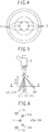
- FIG. 3 A central sectional view of the nozzle of the injector 9 is shown in Fig. 3 .
- Fig. 4 A plain view of the nozzle of the injector 9 when viewed from below is shown in Fig. 4 .
- exemplary forms of fuel sprays injected from the injector 9 are shown in Figs. 5 and 6 .
- a plurality of microscopic nozzle holes 13 are circumferentially formed at the end of the injector 9.
- the diameter of a nozzle hole 13 is for example 100 to 200 ⁇ m.
- Fine fuel sprays having a Sauter mean diameter of about 5 to 20 micrometers are formed by injecting high-pressure fuel (for example, 10 to 20 MPa) from the microscopic nozzle holes.
- Fuel injection is started and ended by a solenoid, a piezoelectric element, a magnetostrictive element, etc. (not shown) vertically driving a valve in the injector 9.
- Fig. 5 shows exemplary outer appearances of fuel sprays injected into a static atmosphere
- Fig. 6 shows a sectional view of forms of fuel sprays taken along the A-A line of Fig. 5
- a plurality of nozzle holes 13 are circumferentially formed at the end of the injector 9; an upper fuel spray 10a, a center fuel spray 11a, and side fuel sprays 12a to 12d are formed from each nozzle hole.
- the injector 9 is provided so that the upper fuel spray 10a is on the ignition plug side.
- the fuel injection timing can be changed in diverse ways according to operating conditions of the engine. For example, immediately after a start of the engine, the engine temperature is low; accordingly, fuel injection is performed in the compression stroke in order to stabilize combustion.
- fuel injection is performed in the intake stroke in order to fully mix the fuel with air in the cylinder. Further, if engine load is comparatively small, in order to improve fuel efficiency, so-called stratified lean-burn combustion may be performed by injecting fuel in the compression stroke to concentrate fuel around the ignition plug even after the engine has warmed up.
- the fuel injection timing is suitably changed by the engine control unit (ECU) of the internal combustion engine so as to optimize fuel efficiency, exhaust gas, and engine power.
- ECU engine control unit
- Fig. 7 shows forms of fuel sprays in the combustion chamber when fuel injection is performed in the middle of the intake stroke.
- the diagram shows a condition in the combustion chamber at 90 degrees ATDC where, for example, the engine rotational speed is 2000 r/min and the fuel injection start timing is 70 degrees after the intake T.D.C. (70 degrees ATDC). Further,
- Fig. 8 is a plan view showing a condition in the combustion chamber at the same timing as Fig. 7 when viewed from the top (ignition plug side).
- the upper fuel spray 10a injected from the injector 9 is injected toward slightly below an electrode of the ignition plug 4, and the side sprays 12c and 12d are injected toward the intake side of the piston.
- the fuel sprays do not easily impinge on the wall of the combustion chamber, for example, the engine head, the intake valve, the exhaust valve, the cylinder bore wall surface, piston surface, etc. Further, the fuel sprays are injected over a wide range, resulting in favorable dispersion thereof into the combustion chamber. If a fuel spray impinges on the wall surface, a liquid film is formed on the wall surface, resulting in a decreased evaporation speed.
- Fig. 9 shows a condition in the combustion chamber at a later stage of the compression stroke (for example, 40 degrees before the compression T.D.C.) following the condition of Figs. 7 and 8 .
- the fuel injected in the intake stroke immediately evaporates to mix with air during the same stroke.
- an air-fuel mixture having almost uniform concentrations is formed at a later stage of the compression stroke.
- the air-fuel mixture in the combustion chamber is ignited by the ignition plug to make combustion (not shown).
- Fig. 10 is a block diagram showing an overall configuration of the engine.
- the piston 3 is connected with a crankshaft 18 through a connecting rod 17.
- the crankshaft 18 is provided with a crank angle sensor 19 which can detect a crank angle and an engine rotational speed.
- the cylinder block 2 is provided with a water temperature sensor 20 which detects a cooling water temperature.
- An accelerator 21 is provided with an accelerator opening sensor 22 which detects the depressed amount of the accelerator by the driver.
- the intake pipe 5 is provided with a throttle valve 23 which can control the quantity of intake air.
- An air flow sensor (not shown) which can detect the quantity of intake air is provided on an upstream side of the intake pipe 5.
- the exhaust pipe 6 is provided with a three-way catalyst 14, an air-fuel ratio sensor 15 is provided on an upstream side thereof, and an O2 sensor 16 is provided on a downstream side thereof.
- a low-pressure pump 26 provided in a fuel tank 25 is connected to the injector 9 through a fuel pipe 24, and a high-pressure pump 27 which further pressurizes the fuel and a fuel pressure sensor 28 which can detect the fuel pressure are provided in the middle of the fuel pipe 24.
- the engine control unit (ECU) 29 is composed of a central processing unit (CPU) 30 which performs calculation processing according to a set program; a read-only memory (ROM) 31 which stores a control program and data necessary for calculations; a random access memory (RAM) 32 which temporarily stores a calculation result; an input circuit 33 which receives signals from each sensor; and an output circuit 34 which transmits signals to each apparatus based on the calculation result.
- CPU central processing unit
- ROM read-only memory
- RAM random access memory
- the lightness of the present fuel is to be obtained by means provided in the claims.
- Various known methods for obtaining the lightness of the fuel are disclosed, for example, in JP-A-9-151777 .
- the lightness refers to an index of the ease with which fuel evaporates and is defined as a numerical value that is proportional to the evaporation speed (amount of fuel evaporation per unit time) thereof.
- the lightness becomes 0 in the case of the heaviest gasoline and 1 in the case of the lightest gasoline; in the continuum between 1 and 0, the lightness takes a certain numerical value corresponding to the fuel evaporation speed.
- Figs. 11 and 12 Fuel injection timing in the intake stroke injection mode are shown in Figs. 11 and 12 .
- Fig. 11 is a fuel injection timing chart for each fuel lightness
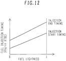
- Fig. 12 is a graph showing a relation between fuel injection timing (fuel injection start and end timing) and fuel lightness.
- the fuel injection timing in the intake stroke injection mode is changed according to the fuel lightness. Specifically, in the case of fuels having lower lightness (i.e., lower evaporation speed), the fuel injection start and end timing is each made earlier; in the case of fuels having higher lightness or fuels which easily evaporate (i.e., higher evaporation speed), the fuel injection start and end timing is each made later.
- an interval between the fuel injection start and end timings is determined so that the air-fuel ratio (i.e., a ratio of the air mass to be charged in the combustion chamber to the fuel mass to be injected therein) becomes a predetermined value (for example, 12 to 14.7).
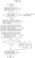
- Fig. 13 is a flow chart showing the fuel injection timing determination procedures in the intake stroke injection mode.
- the lightness of the present fuel is obtained with the above-mentioned known techniques (disclosed, for example, in JP-A-9-151777 ), and the lightness is then stored in the RAM of the ECU (processing 100).
- the ECU obtains a required torque for the engine from output values of the accelerator opening sensor, the crank angle sensor, etc. and then determines whether or not the present mode is the intake stroke injection mode based on various pieces of information, such as the required torque, a cooling water temperature detected by the water temperature sensor, etc. (processing 101).
- the ECU obtains a fuel injection timing correction value based on the fuel lightness already stored in the RAM.
- the fuel injection timing correction value corresponding to the fuel lightness is provided in advance as a table or function in the RAM of the ECU for each required torque and rotational speed of the engine.
- a fuel injection timing correction value corresponding to the present required torque and rotational speed is obtained by use of this table or function (processing 102).
- a fuel injection start timing ITs is obtained in processing 103.
- the fuel injection start timing ITs is obtained by adding the fuel injection timing correction value obtained in processing 102 to reference injection start timing corresponding to the present required torque and rotational speed.
- the reference injection start timing which is the injection start timing at which engine power is maximized when the fuel lightness is 0 (heaviest) is preset as a table or function in the RAM of the ECU for each required torque and rotational speed of the engine.
- fuel injection end timing ITe is obtained by adding an injection period to the fuel injection start timing ITs obtained in processing 103.
- the injection period is obtained as a time period necessary to inject the required quantity of fuel at the present fuel pressure detected by the fuel pressure sensor.
- the required quantity of fuel is obtained so that the air-fuel ratio (i.e., a ratio of the air mass charged in the combustion chamber, which is detected by the air flow sensor, to the fuel mass to be injected therein) becomes a predetermined value (for example, 12).
- the fuel injection end timing ITe obtained in processing 104 is compared with a predetermined fuel injection timing limit ITL (processing 105).
- ITL is defined as timing slightly earlier than intake valve closing timing IVC (for example, ITL is defined as 210 degrees ATDC while IVC as 220 degrees ATDC). Further, it may be possible to change ITL according to the engine rotational speed, etc. instead of setting it to a constant fixed value.
- processing 106 corrects the fuel injection start timing ITs and the fuel injection end timing ITe. Specifically, advance angle correction is made for the fuel injection start timing ITs and the fuel injection end timing ITe so that the fuel injection end timing ITe agrees with the fuel injection timing limit ITL while maintaining the fuel injection period.
- the density of gas ⁇ 0 having initial temperature T0 and pressure P is represented by Formula 1 based on the equation of state.
- ⁇ 0 P / RT 0 where R is the gas constant.
- ⁇ T mfLv / mgCp
- mf the mass of evaporated fuel
- mg the mass of gas
- Lv the evaporation latent heat
- Cp the isobaric specific heat of gas
- Formula 4 denotes the rate of a density increase accompanying evaporative cooling caused by the fuel evaporation.
- Fig. 15 is a graph showing the dependence of the density increase rate represented by Formula 4 on an initial gas temperature T0. This graph denotes that the density increase rate after fuel evaporation increases with decreasing initial gas temperature.
- Fig. 16 shows an example of the time history of the gas temperature in the combustion chamber.
- the gas temperature in the combustion chamber is very high because of the influence of a residual combustion gas in the combustion chamber.
- air almost at a normal temperature (fresh air) is charged in the combustion chamber decreasing the gas temperature.
- the gas temperature in the combustion chamber becomes the lowest at the intake B.D.C.
- the fuel injection timing is continuously changed according to continuous fuel lightness values as shown in Fig. 12
- the same effect can be obtained by providing a threshold value of the fuel lightness and delaying stepwise the fuel injection timing when the fuel lightness is higher than the threshold value.
- this method is advantageous in that the determination of lightness is easy to control.
- the fuel injection timing in relation to the fuel lightness
- a parameter for changing the fuel evaporation speed for example, the engine cooling water temperature can be used. Specifically, the higher the cooling water temperature, the higher becomes the engine temperature and accordingly the easier for the fuel injected into the combustion chamber to evaporate. Then, as shown in Fig. 19 , the engine power can be improved by detecting an engine cooling water temperature by use of a cooling water temperature sensor and delaying the fuel injection timing in the intake stroke injection mode with increasing cooling water temperature.
- the engine cooling water temperature is the lowest at a cold start of the engine, rises as the engine warms up, and then is maintained almost at a constant temperature (80 to 90°C) after completion of warming up. Therefore, in the time interval from the engine start to the warm-up completion time, the engine power can be improved by delaying the fuel injection timing in the intake stroke injection mode in relation to the elapsed time from the engine start instead of engine cooling water temperature (refer to Fig. 20 ).
- the outside air temperature can be used as another parameter for changing the fuel evaporation speed. Specifically, the higher the outside air temperature, the higher become the engine temperature, the intake gas temperature, and the fuel temperature and accordingly the easier for the fuel injected into the combustion chamber to evaporate. Then, as shown in the Fig. 21 , the engine power can be improved by detecting an outside air temperature by use of an outside air temperature sensor and delaying the fuel injection timing in the intake stroke injection mode with increasing outside air temperature.
- the fuel temperature can be used. Specifically, the higher the fuel temperature, the easier for the fuel injected into the combustion chamber to evaporate. Then, as shown in the Fig. 22 , the engine power can be improved by detecting a fuel temperature by use of a fuel temperature sensor and delaying the fuel injection timing in the intake stroke injection mode with increasing fuel temperature.
- the fuel pressure can be used.
- the droplet diameter of a fuel spray injected from the injector decreases with increasing fuel pressure as shown in Fig. 23 .
- the higher the fuel pressure the easier for the fuel injected into the combustion chamber to evaporate.
- a fuel pressure is detected with a fuel pressure sensor, and the fuel injection timing in the intake stroke injection mode is then delayed with increasing fuel pressure. Since the rate of fuel injection from the injector (injection quantity per unit time) increases with increasing fuel pressure as shown in Fig. 24 , if the fuel pressure rises, the injection period necessary to inject a predetermined fuel quantity decreases. Therefore, the change rate of the injection end timing in relation to the fuel pressure is smaller than that of the injection start timing in relation to the same.
- FIG. 25 is an example of an engine configuration wherein a tumble control valve is provided.
- a tumble control valve is provided on an upstream side of the intake port 5.
- the structure of the tumble control valve is such that semicircular plates 23 are attached to a swinging shaft 22 of a motor 21. The semicircular plates 23 swing around the swinging shaft 22 based on a command from the ECU (not shown).
- the tumble control valve is open as shown in Fig. 26 , air enters the combustion chamber through the entire section of the intake port; therefore, bi-directional longitudinal vortexes (tumbles) are generated in the combustion chamber.
- the vortexes cancel each other, damping the entire vortex flow in the combustion chamber.
- the tumble control valve is closed, air enters the combustion chamber through the upper half section of the intake port; therefore, a strong unidirectional longitudinal vortex is generated in the combustion chamber.
- the strong longitudinal vortex violently interferes with fuel sprays injected into the combustion chamber, promoting atomization and evaporation of the fuel sprays. This makes it possible to change the fuel evaporation speed in the combustion chamber by means of the opening of the tumble control valve.
- the opening of the tumble control valve can be used as still another parameter for changing the fuel evaporation speed.
- the smaller the opening of the tumble control valve i.e., the higher the intensity of tumbles in the combustion chamber), the easier for the fuel injected into the combustion chamber to evaporate.
- the engine power can be improved by delaying the fuel injection timing in the intake stroke injection mode with decreasing opening of the tumble control valve.
- tumble control valve which generates longitudinal vortexes in the combustion chamber has been described above, the same effect as that of the tumble control valve can also be obtained by performing the same control on a swirl control valve which generates lateral vortexes (swirls) in the combustion chamber.
- Ethanol-blended gasoline is known as a mixed fuel. Since each saturated vapor pressure differs between ethanol and gasoline, the saturated vapor pressure of the mixed fuel depends on the concentration of mixed ethanol as shown in Fig. 28 . Generally, the saturated vapor pressure of the mixed fuel increases with increasing ethanol concentration. This means that the fuel evaporation speed increases with increasing ratio of mixed ethanol. Then, as shown in the Fig. 29 , the engine power can be improved by detecting a concentration of ethanol contained in the fuel and delaying the fuel injection timing in the intake stroke injection mode with increasing ethanol concentration. In connection with detection of the ethanol concentration, disclosures, for example, in JP-A-2006-77683 can be utilized.
- the calorific value per unit mass of ethanol is smaller than that of gasoline. Therefore, in order to obtain the same calorific value, it is necessary to inject a more quantity of ethanol-blended fuel than the quantity of gasoline to solely be injected. Therefore, as shown in Fig. 29 , the injection period increases with increasing ethanol concentration.
- the fuel injection end timing In order to increase the quantity of air to be filled in the combustion chamber by the evaporation latent heat effect of fuel, it is necessary that the fuel injection end timing be earlier than the valve closing timing of the intake valve (IVC).
- IVC intake valve
- a required quantity of fuel increases with increasing ethanol concentration, which lengthens a fuel injection period. Therefore, as shown in Fig. 30 , the fuel injection start timing may be made earlier with increasing ethanol concentration. Also in this case, the engine power can be improved by delaying intermediate timing of the fuel injection start and end timing (i.e., average fuel injection timing) with increasing ethanol concentration.
- the present invention provides a fuel injection controller used for a direct injection internal combustion engine.
- the present invention is not limited to the types of injector, presence or absence of an air flow mechanism in the cylinder, attachment position of the injector (side injection or center injection), and fuel injection method (single injection or multiple injections), and is widely applicable in combination with each other.
Landscapes
- Engineering & Computer Science (AREA)
- Chemical & Material Sciences (AREA)
- Combustion & Propulsion (AREA)
- Mechanical Engineering (AREA)
- General Engineering & Computer Science (AREA)
- Electrical Control Of Air Or Fuel Supplied To Internal-Combustion Engine (AREA)
- Combined Controls Of Internal Combustion Engines (AREA)
Claims (3)
- Steuereinheit (29) einer Brennkraftmaschine mit Direkteinspritzung, die ausgelegt ist zum
Einspritzen von Kraftstoff direkt in einen Zylinder mindestens in einem Einlasstakt und
Zünden verdampften Kraftstoffs darin mittels einer Zündkerze (4), wobei die Steuereinheit (29) Folgendes umfasst:ein Mittel zum Detektieren von Kraftstoffleichtigkeit durch Detektieren von Kraftstoffkomponenten, wobeidie Steuereinheit (29) ausgelegt ist, den Kraftstoffeinspritzzeitpunkt näher am Ende des Einlasstakts zu setzen, wenn die Kraftstoffleichtigkeit höher wird, nur zu einer Betriebszeit, wenn eine Drosselklappe (23), die die Luftmenge steuert, die dem Zylinder der Brennkraftmaschine mit Direkteinspritzung zugeführt wird, vollständig öffnet. - Steuereinheit (29) nach Anspruch 1, wobei
die Steuereinheit (29) ausgelegt ist, den Kraftstoffeinspritzzeitpunkt näher am Ende des Einlasstakts zu setzen, wenn eine detektierte Konzentration von Ethanol in einem gemischten Kraftstoff höher wird, nur zu einer Betriebszeit, wenn eine Drosselklappe (23), die die Luftmenge steuert, die dem Zylinder der Brennkraftmaschine mit Direkteinspritzung zugeführt wird, vollständig öffnet. - Steuereinheit (29) nach Anspruch 1 oder 2, wobei
die Steuereinheit (29) ausgelegt ist, den Kraftstoffeinspritzstartzeitpunkt zu korrigieren, damit das Einspritzen von Kraftstoff vor dem Einlassventilschließzeitpunkt endet.
Applications Claiming Priority (1)
| Application Number | Priority Date | Filing Date | Title |
|---|---|---|---|
| JP2007048360A JP4379479B2 (ja) | 2007-02-28 | 2007-02-28 | 筒内噴射式エンジンの制御方法、当該制御方法を実施するための制御装置、当該制御装置に用いられる制御回路装置 |
Publications (3)
| Publication Number | Publication Date |
|---|---|
| EP1965062A2 EP1965062A2 (de) | 2008-09-03 |
| EP1965062A3 EP1965062A3 (de) | 2014-07-16 |
| EP1965062B1 true EP1965062B1 (de) | 2018-07-18 |
Family
ID=39472523
Family Applications (1)
| Application Number | Title | Priority Date | Filing Date |
|---|---|---|---|
| EP07024126.0A Ceased EP1965062B1 (de) | 2007-02-28 | 2007-12-12 | Steuerverfahren für einen Direkteinspritzmotor, Steuergerät zur Anwendung des Steuerverfahrens und Steuerschaltungsvorrichtung für das Steuergerät |
Country Status (3)
| Country | Link |
|---|---|
| US (1) | US7983832B2 (de) |
| EP (1) | EP1965062B1 (de) |
| JP (1) | JP4379479B2 (de) |
Families Citing this family (23)
| Publication number | Priority date | Publication date | Assignee | Title |
|---|---|---|---|---|
| EP2047079A1 (de) * | 2006-08-04 | 2009-04-15 | Toyota Jidosha Kabushiki Kaisha | Ottoverbrennungsmotor mit direkteinspritzung und einspritzverfahren dafür |
| JP5168233B2 (ja) * | 2009-05-28 | 2013-03-21 | 日産自動車株式会社 | エンジンの燃料噴射制御装置 |
| DE102009028798A1 (de) * | 2009-08-21 | 2011-02-24 | Robert Bosch Gmbh | Verfahren zum Durchführen einer Saugrohreinspritzung |
| JP5581852B2 (ja) * | 2010-06-29 | 2014-09-03 | マツダ株式会社 | 直噴ガソリンエンジンの制御装置 |
| JP5572107B2 (ja) * | 2011-01-31 | 2014-08-13 | 本田技研工業株式会社 | 内燃機関の燃料噴射制御装置 |
| JP5626152B2 (ja) * | 2011-07-14 | 2014-11-19 | トヨタ自動車株式会社 | 燃料噴射システム |
| US20130275025A1 (en) * | 2012-04-11 | 2013-10-17 | Delphi Technologies, Inc. | System and method for controlling a heated fuel injector in an internal combustion engine |
| JP2014015907A (ja) * | 2012-07-11 | 2014-01-30 | Hitachi Automotive Systems Ltd | 内燃機関の燃料噴射制御装置 |
| DE102012214676B4 (de) * | 2012-08-17 | 2014-05-28 | Ford Global Technologies, Llc | Verfahren und Vorrichtung zur Steuerung eines gasbetriebenen Verbrennungsmotors |
| JP6152685B2 (ja) * | 2013-04-09 | 2017-06-28 | トヨタ自動車株式会社 | 燃料噴射量制御装置 |
| JP6330260B2 (ja) * | 2013-05-21 | 2018-05-30 | 日産自動車株式会社 | 内燃機関の制御装置 |
| JP2015145641A (ja) * | 2014-02-03 | 2015-08-13 | トヨタ自動車株式会社 | 内燃機関の燃料噴射制御装置 |
| JP6057021B2 (ja) * | 2014-05-15 | 2017-01-11 | 日産自動車株式会社 | 内燃機関の燃料噴射制御装置及び燃料噴射制御方法 |
| JP6237659B2 (ja) * | 2015-01-21 | 2017-11-29 | トヨタ自動車株式会社 | 火花点火式内燃機関の制御装置 |
| JP6047217B1 (ja) * | 2015-11-10 | 2016-12-21 | 川崎重工業株式会社 | ガスエンジン駆動システム |
| JP6397437B2 (ja) * | 2016-02-24 | 2018-09-26 | 本田技研工業株式会社 | 直噴式内燃機関 |
| JP6418206B2 (ja) * | 2016-08-10 | 2018-11-07 | トヨタ自動車株式会社 | エンジンの始動制御装置 |
| CN106353103B (zh) * | 2016-10-12 | 2019-04-05 | 中国船舶重工集团公司第七一一研究所 | 一种大功率天然气喷射阀测试方法 |
| KR101926927B1 (ko) * | 2016-11-14 | 2018-12-07 | 현대자동차주식회사 | Ffv의 엔진 시동 제어 방법 |
| JP6508240B2 (ja) * | 2017-03-27 | 2019-05-08 | マツダ株式会社 | 火花点火式内燃機関 |
| JP6741166B2 (ja) * | 2017-09-20 | 2020-08-19 | 日産自動車株式会社 | 火花点火式内燃機関の燃料噴射制御方法および燃料噴射装置 |
| JP6992561B2 (ja) * | 2018-02-06 | 2022-01-13 | 株式会社デンソー | 燃料噴射制御装置 |
| US20190360421A1 (en) * | 2018-05-24 | 2019-11-28 | GM Global Technology Operations LLC | Method to evaluate the instantaneous fuel to torque ice efficiency status |
Citations (1)
| Publication number | Priority date | Publication date | Assignee | Title |
|---|---|---|---|---|
| DE102004001825A1 (de) * | 2003-01-14 | 2004-09-02 | Denso Corp., Kariya | Steuervorrichtung für eine Brennkraftmaschine mit innerer Verbrennung |
Family Cites Families (14)
| Publication number | Priority date | Publication date | Assignee | Title |
|---|---|---|---|---|
| JP3345464B2 (ja) * | 1993-06-23 | 2002-11-18 | 富士重工業株式会社 | エンジンの燃料供給装置 |
| JP3147770B2 (ja) | 1996-04-10 | 2001-03-19 | トヨタ自動車株式会社 | 内燃機関の制御装置 |
| DE69725826T2 (de) * | 1996-11-18 | 2004-08-12 | Toyota Jidosha K.K., Toyota | Regler für Brennkraftmaschinen mit Schichtladung |
| US6062201A (en) * | 1997-05-13 | 2000-05-16 | Denso Corporation | Fuel injection control for internal combustion engine |
| JP2002013428A (ja) * | 2000-06-30 | 2002-01-18 | Mitsubishi Motors Corp | 筒内噴射型内燃機関 |
| JP2002089324A (ja) | 2000-09-18 | 2002-03-27 | Mitsubishi Electric Corp | 筒内噴射エンジンの燃料噴射制御装置 |
| JP2003097317A (ja) * | 2001-09-26 | 2003-04-03 | Hitachi Ltd | 予混合圧縮着火エンジンの着火時期制御方法 |
| US20040000275A1 (en) * | 2002-05-01 | 2004-01-01 | Mcintyre Michael Gene | Multi map fuel detection fuel injection |
| JP4115237B2 (ja) * | 2002-10-16 | 2008-07-09 | 株式会社小松製作所 | ディーゼルエンジン |
| JP2004239230A (ja) * | 2003-02-10 | 2004-08-26 | Nissan Motor Co Ltd | 内燃機関の燃焼制御装置 |
| DE10330540A1 (de) * | 2003-07-01 | 2005-01-20 | Volkswagen Ag | Verfahren zum Betrieb eines direkteinspritzenden Verbrennungsmotors sowie direkteinspritzender Verbrennungsmotor |
| US7194999B2 (en) * | 2004-07-26 | 2007-03-27 | Nissan Motor Co., Ltd. | Combustion control apparatus for direct-injection spark-ignition internal combustion engine |
| JP2006090202A (ja) | 2004-09-24 | 2006-04-06 | Nissan Motor Co Ltd | 筒内直接噴射式火花点火内燃機関の制御装置 |
| JP2007032326A (ja) | 2005-07-25 | 2007-02-08 | Toyota Motor Corp | 内燃機関の制御装置 |
-
2007
- 2007-02-28 JP JP2007048360A patent/JP4379479B2/ja not_active Expired - Fee Related
- 2007-12-12 EP EP07024126.0A patent/EP1965062B1/de not_active Ceased
- 2007-12-13 US US11/956,040 patent/US7983832B2/en not_active Expired - Fee Related
Patent Citations (1)
| Publication number | Priority date | Publication date | Assignee | Title |
|---|---|---|---|---|
| DE102004001825A1 (de) * | 2003-01-14 | 2004-09-02 | Denso Corp., Kariya | Steuervorrichtung für eine Brennkraftmaschine mit innerer Verbrennung |
Also Published As
| Publication number | Publication date |
|---|---|
| JP2008208811A (ja) | 2008-09-11 |
| US7983832B2 (en) | 2011-07-19 |
| JP4379479B2 (ja) | 2009-12-09 |
| EP1965062A2 (de) | 2008-09-03 |
| US20080208438A1 (en) | 2008-08-28 |
| EP1965062A3 (de) | 2014-07-16 |
Similar Documents
| Publication | Publication Date | Title |
|---|---|---|
| EP1965062B1 (de) | Steuerverfahren für einen Direkteinspritzmotor, Steuergerät zur Anwendung des Steuerverfahrens und Steuerschaltungsvorrichtung für das Steuergerät | |
| CN101151451B (zh) | 用于发动机的燃料喷射控制设备 | |
| JP2003097317A (ja) | 予混合圧縮着火エンジンの着火時期制御方法 | |
| US10968859B2 (en) | Premixed compression ignition engine and method for controlling premixed compression ignition engine | |
| JP4297288B2 (ja) | 予混合圧縮着火エンジンの着火時期制御方法 | |
| JP3775498B2 (ja) | 蓄圧式燃料噴射装置 | |
| CN100424331C (zh) | 预混合压缩自点火式内燃机 | |
| JP2014501348A (ja) | 内燃機関用噴射装置の操作方法 | |
| CN101484680A (zh) | 用于直喷式火花点火内燃发动机的燃料喷射控制方法 | |
| JP3975695B2 (ja) | 自己着火式エンジン | |
| JP4117799B2 (ja) | 予混合圧縮着火エンジンの着火時期制御方法 | |
| CN100422534C (zh) | 用于直接喷射火花塞点火式内燃机的燃烧控制系统和方法 | |
| JP4089641B2 (ja) | 内燃機関のegr制御装置 | |
| JP5104195B2 (ja) | 火花点火内燃機関 | |
| JP2009102998A (ja) | 火花点火内燃機関 | |
| JP2010265814A (ja) | 内燃機関の制御装置 | |
| JP3852230B2 (ja) | 筒内噴射式火花点火機関 | |
| JP2000179380A (ja) | 内燃機関の制御装置 | |
| JP2019138248A (ja) | 燃料噴射制御装置 | |
| CN100516486C (zh) | 用于内燃机的控制设备 | |
| JP2007192235A (ja) | 火花点火内燃機関の制御装置及び方法 | |
| JP2005127192A (ja) | 内燃機関の燃料噴射制御装置 | |
| JP3635670B2 (ja) | 火花点火内燃機関の制御装置及び方法 | |
| JP7803269B2 (ja) | エンジン装置 | |
| JP5262991B2 (ja) | 火花点火式直噴エンジンの吸気制御装置 |
Legal Events
| Date | Code | Title | Description |
|---|---|---|---|
| PUAI | Public reference made under article 153(3) epc to a published international application that has entered the european phase |
Free format text: ORIGINAL CODE: 0009012 |
|
| AK | Designated contracting states |
Kind code of ref document: A2 Designated state(s): AT BE BG CH CY CZ DE DK EE ES FI FR GB GR HU IE IS IT LI LT LU LV MC MT NL PL PT RO SE SI SK TR |
|
| AX | Request for extension of the european patent |
Extension state: AL BA HR MK RS |
|
| 17P | Request for examination filed |
Effective date: 20090619 |
|
| PUAL | Search report despatched |
Free format text: ORIGINAL CODE: 0009013 |
|
| AK | Designated contracting states |
Kind code of ref document: A3 Designated state(s): AT BE BG CH CY CZ DE DK EE ES FI FR GB GR HU IE IS IT LI LT LU LV MC MT NL PL PT RO SE SI SK TR |
|
| AX | Request for extension of the european patent |
Extension state: AL BA HR MK RS |
|
| RIC1 | Information provided on ipc code assigned before grant |
Ipc: F02D 41/40 20060101ALI20140611BHEP Ipc: F02D 41/34 20060101ALI20140611BHEP Ipc: F02D 41/38 20060101ALI20140611BHEP Ipc: F02D 41/04 20060101AFI20140611BHEP Ipc: F02D 41/06 20060101ALN20140611BHEP |
|
| AKX | Designation fees paid |
Designated state(s): DE |
|
| AXX | Extension fees paid |
Extension state: BA Extension state: RS Extension state: AL Extension state: HR Extension state: MK |
|
| 17Q | First examination report despatched |
Effective date: 20151209 |
|
| RIC1 | Information provided on ipc code assigned before grant |
Ipc: F02D 41/38 20060101ALI20170119BHEP Ipc: F02D 41/06 20060101ALN20170119BHEP Ipc: F02D 41/34 20060101ALI20170119BHEP Ipc: F02D 41/40 20060101ALI20170119BHEP Ipc: F02D 41/04 20060101AFI20170119BHEP |
|
| RIC1 | Information provided on ipc code assigned before grant |
Ipc: F02D 41/40 20060101ALI20170120BHEP Ipc: F02D 41/38 20060101ALI20170120BHEP Ipc: F02D 41/06 20060101ALN20170120BHEP Ipc: F02D 41/34 20060101ALI20170120BHEP Ipc: F02D 41/04 20060101AFI20170120BHEP |
|
| STAA | Information on the status of an ep patent application or granted ep patent |
Free format text: STATUS: EXAMINATION IS IN PROGRESS |
|
| RIC1 | Information provided on ipc code assigned before grant |
Ipc: F02D 41/38 20060101ALI20170215BHEP Ipc: F02D 41/06 20060101ALN20170215BHEP Ipc: F02D 41/40 20060101ALI20170215BHEP Ipc: F02D 41/04 20060101AFI20170215BHEP Ipc: F02D 41/34 20060101ALI20170215BHEP |
|
| GRAP | Despatch of communication of intention to grant a patent |
Free format text: ORIGINAL CODE: EPIDOSNIGR1 |
|
| STAA | Information on the status of an ep patent application or granted ep patent |
Free format text: STATUS: GRANT OF PATENT IS INTENDED |
|
| INTG | Intention to grant announced |
Effective date: 20180214 |
|
| GRAS | Grant fee paid |
Free format text: ORIGINAL CODE: EPIDOSNIGR3 |
|
| GRAA | (expected) grant |
Free format text: ORIGINAL CODE: 0009210 |
|
| STAA | Information on the status of an ep patent application or granted ep patent |
Free format text: STATUS: THE PATENT HAS BEEN GRANTED |
|
| RIN1 | Information on inventor provided before grant (corrected) |
Inventor name: FUJII, HIROSHI Inventor name: SUKEGAWA, YOSHIHIRO |
|
| AK | Designated contracting states |
Kind code of ref document: B1 Designated state(s): DE |
|
| REG | Reference to a national code |
Ref country code: DE Ref legal event code: R096 Ref document number: 602007055395 Country of ref document: DE |
|
| REG | Reference to a national code |
Ref country code: DE Ref legal event code: R097 Ref document number: 602007055395 Country of ref document: DE |
|
| PLBE | No opposition filed within time limit |
Free format text: ORIGINAL CODE: 0009261 |
|
| STAA | Information on the status of an ep patent application or granted ep patent |
Free format text: STATUS: NO OPPOSITION FILED WITHIN TIME LIMIT |
|
| 26N | No opposition filed |
Effective date: 20190423 |
|
| PGFP | Annual fee paid to national office [announced via postgrant information from national office to epo] |
Ref country code: DE Payment date: 20201201 Year of fee payment: 14 |
|
| REG | Reference to a national code |
Ref country code: DE Ref legal event code: R119 Ref document number: 602007055395 Country of ref document: DE |
|
| PG25 | Lapsed in a contracting state [announced via postgrant information from national office to epo] |
Ref country code: DE Free format text: LAPSE BECAUSE OF NON-PAYMENT OF DUE FEES Effective date: 20220701 |