EP1950040A2 - Flüssigkeitsausstoß-Aufzeichnungskopf und Herstellungsverfahren dafür - Google Patents
Flüssigkeitsausstoß-Aufzeichnungskopf und Herstellungsverfahren dafür Download PDFInfo
- Publication number
- EP1950040A2 EP1950040A2 EP08154340A EP08154340A EP1950040A2 EP 1950040 A2 EP1950040 A2 EP 1950040A2 EP 08154340 A EP08154340 A EP 08154340A EP 08154340 A EP08154340 A EP 08154340A EP 1950040 A2 EP1950040 A2 EP 1950040A2
- Authority
- EP
- European Patent Office
- Prior art keywords
- orifice plate
- substrate
- recording head
- flow path
- liquid discharge
- Prior art date
- Legal status (The legal status is an assumption and is not a legal conclusion. Google has not performed a legal analysis and makes no representation as to the accuracy of the status listed.)
- Granted
Links
Images






Classifications
-
- B—PERFORMING OPERATIONS; TRANSPORTING
- B41—PRINTING; LINING MACHINES; TYPEWRITERS; STAMPS
- B41J—TYPEWRITERS; SELECTIVE PRINTING MECHANISMS, i.e. MECHANISMS PRINTING OTHERWISE THAN FROM A FORME; CORRECTION OF TYPOGRAPHICAL ERRORS
- B41J2/00—Typewriters or selective printing mechanisms characterised by the printing or marking process for which they are designed
- B41J2/005—Typewriters or selective printing mechanisms characterised by the printing or marking process for which they are designed characterised by bringing liquid or particles selectively into contact with a printing material
- B41J2/01—Ink jet
-
- B—PERFORMING OPERATIONS; TRANSPORTING
- B41—PRINTING; LINING MACHINES; TYPEWRITERS; STAMPS
- B41J—TYPEWRITERS; SELECTIVE PRINTING MECHANISMS, i.e. MECHANISMS PRINTING OTHERWISE THAN FROM A FORME; CORRECTION OF TYPOGRAPHICAL ERRORS
- B41J2/00—Typewriters or selective printing mechanisms characterised by the printing or marking process for which they are designed
- B41J2/005—Typewriters or selective printing mechanisms characterised by the printing or marking process for which they are designed characterised by bringing liquid or particles selectively into contact with a printing material
- B41J2/01—Ink jet
- B41J2/135—Nozzles
- B41J2/16—Production of nozzles
- B41J2/1621—Manufacturing processes
- B41J2/164—Manufacturing processes thin film formation
- B41J2/1645—Manufacturing processes thin film formation thin film formation by spincoating
-
- B—PERFORMING OPERATIONS; TRANSPORTING
- B41—PRINTING; LINING MACHINES; TYPEWRITERS; STAMPS
- B41J—TYPEWRITERS; SELECTIVE PRINTING MECHANISMS, i.e. MECHANISMS PRINTING OTHERWISE THAN FROM A FORME; CORRECTION OF TYPOGRAPHICAL ERRORS
- B41J2/00—Typewriters or selective printing mechanisms characterised by the printing or marking process for which they are designed
- B41J2/005—Typewriters or selective printing mechanisms characterised by the printing or marking process for which they are designed characterised by bringing liquid or particles selectively into contact with a printing material
- B41J2/01—Ink jet
- B41J2/135—Nozzles
- B41J2/14—Structure thereof only for on-demand ink jet heads
- B41J2/14016—Structure of bubble jet print heads
- B41J2/14032—Structure of the pressure chamber
- B41J2/1404—Geometrical characteristics
-
- B—PERFORMING OPERATIONS; TRANSPORTING
- B41—PRINTING; LINING MACHINES; TYPEWRITERS; STAMPS
- B41J—TYPEWRITERS; SELECTIVE PRINTING MECHANISMS, i.e. MECHANISMS PRINTING OTHERWISE THAN FROM A FORME; CORRECTION OF TYPOGRAPHICAL ERRORS
- B41J2/00—Typewriters or selective printing mechanisms characterised by the printing or marking process for which they are designed
- B41J2/005—Typewriters or selective printing mechanisms characterised by the printing or marking process for which they are designed characterised by bringing liquid or particles selectively into contact with a printing material
- B41J2/01—Ink jet
- B41J2/135—Nozzles
- B41J2/14—Structure thereof only for on-demand ink jet heads
- B41J2/1433—Structure of nozzle plates
-
- B—PERFORMING OPERATIONS; TRANSPORTING
- B41—PRINTING; LINING MACHINES; TYPEWRITERS; STAMPS
- B41J—TYPEWRITERS; SELECTIVE PRINTING MECHANISMS, i.e. MECHANISMS PRINTING OTHERWISE THAN FROM A FORME; CORRECTION OF TYPOGRAPHICAL ERRORS
- B41J2/00—Typewriters or selective printing mechanisms characterised by the printing or marking process for which they are designed
- B41J2/005—Typewriters or selective printing mechanisms characterised by the printing or marking process for which they are designed characterised by bringing liquid or particles selectively into contact with a printing material
- B41J2/01—Ink jet
- B41J2/135—Nozzles
- B41J2/16—Production of nozzles
- B41J2/1601—Production of bubble jet print heads
- B41J2/1603—Production of bubble jet print heads of the front shooter type
-
- B—PERFORMING OPERATIONS; TRANSPORTING
- B41—PRINTING; LINING MACHINES; TYPEWRITERS; STAMPS
- B41J—TYPEWRITERS; SELECTIVE PRINTING MECHANISMS, i.e. MECHANISMS PRINTING OTHERWISE THAN FROM A FORME; CORRECTION OF TYPOGRAPHICAL ERRORS
- B41J2/00—Typewriters or selective printing mechanisms characterised by the printing or marking process for which they are designed
- B41J2/005—Typewriters or selective printing mechanisms characterised by the printing or marking process for which they are designed characterised by bringing liquid or particles selectively into contact with a printing material
- B41J2/01—Ink jet
- B41J2/135—Nozzles
- B41J2/16—Production of nozzles
- B41J2/162—Manufacturing of the nozzle plates
-
- B—PERFORMING OPERATIONS; TRANSPORTING
- B41—PRINTING; LINING MACHINES; TYPEWRITERS; STAMPS
- B41J—TYPEWRITERS; SELECTIVE PRINTING MECHANISMS, i.e. MECHANISMS PRINTING OTHERWISE THAN FROM A FORME; CORRECTION OF TYPOGRAPHICAL ERRORS
- B41J2/00—Typewriters or selective printing mechanisms characterised by the printing or marking process for which they are designed
- B41J2/005—Typewriters or selective printing mechanisms characterised by the printing or marking process for which they are designed characterised by bringing liquid or particles selectively into contact with a printing material
- B41J2/01—Ink jet
- B41J2/135—Nozzles
- B41J2/16—Production of nozzles
- B41J2/1621—Manufacturing processes
- B41J2/1626—Manufacturing processes etching
- B41J2/1629—Manufacturing processes etching wet etching
-
- B—PERFORMING OPERATIONS; TRANSPORTING
- B41—PRINTING; LINING MACHINES; TYPEWRITERS; STAMPS
- B41J—TYPEWRITERS; SELECTIVE PRINTING MECHANISMS, i.e. MECHANISMS PRINTING OTHERWISE THAN FROM A FORME; CORRECTION OF TYPOGRAPHICAL ERRORS
- B41J2/00—Typewriters or selective printing mechanisms characterised by the printing or marking process for which they are designed
- B41J2/005—Typewriters or selective printing mechanisms characterised by the printing or marking process for which they are designed characterised by bringing liquid or particles selectively into contact with a printing material
- B41J2/01—Ink jet
- B41J2/135—Nozzles
- B41J2/16—Production of nozzles
- B41J2/1621—Manufacturing processes
- B41J2/1631—Manufacturing processes photolithography
-
- B—PERFORMING OPERATIONS; TRANSPORTING
- B41—PRINTING; LINING MACHINES; TYPEWRITERS; STAMPS
- B41J—TYPEWRITERS; SELECTIVE PRINTING MECHANISMS, i.e. MECHANISMS PRINTING OTHERWISE THAN FROM A FORME; CORRECTION OF TYPOGRAPHICAL ERRORS
- B41J2/00—Typewriters or selective printing mechanisms characterised by the printing or marking process for which they are designed
- B41J2/005—Typewriters or selective printing mechanisms characterised by the printing or marking process for which they are designed characterised by bringing liquid or particles selectively into contact with a printing material
- B41J2/01—Ink jet
- B41J2/135—Nozzles
- B41J2/16—Production of nozzles
- B41J2/1621—Manufacturing processes
- B41J2/1632—Manufacturing processes machining
-
- B—PERFORMING OPERATIONS; TRANSPORTING
- B41—PRINTING; LINING MACHINES; TYPEWRITERS; STAMPS
- B41J—TYPEWRITERS; SELECTIVE PRINTING MECHANISMS, i.e. MECHANISMS PRINTING OTHERWISE THAN FROM A FORME; CORRECTION OF TYPOGRAPHICAL ERRORS
- B41J2/00—Typewriters or selective printing mechanisms characterised by the printing or marking process for which they are designed
- B41J2/005—Typewriters or selective printing mechanisms characterised by the printing or marking process for which they are designed characterised by bringing liquid or particles selectively into contact with a printing material
- B41J2/01—Ink jet
- B41J2/135—Nozzles
- B41J2/16—Production of nozzles
- B41J2/1621—Manufacturing processes
- B41J2/1637—Manufacturing processes molding
- B41J2/1639—Manufacturing processes molding sacrificial molding
-
- B—PERFORMING OPERATIONS; TRANSPORTING
- B41—PRINTING; LINING MACHINES; TYPEWRITERS; STAMPS
- B41J—TYPEWRITERS; SELECTIVE PRINTING MECHANISMS, i.e. MECHANISMS PRINTING OTHERWISE THAN FROM A FORME; CORRECTION OF TYPOGRAPHICAL ERRORS
- B41J2202/00—Embodiments of or processes related to ink-jet or thermal heads
- B41J2202/01—Embodiments of or processes related to ink-jet heads
- B41J2202/11—Embodiments of or processes related to ink-jet heads characterised by specific geometrical characteristics
Definitions
- the present invention relates to a liquid discharge recording head (ink jet recording head) used in liquid discharge recording (ink jet recording) for discharging liquid such as ink toward a recording medium, and a method for manufacturing such a liquid discharge recording head.
- an orifice plate 105 having a plurality of ink discharge ports 106 is joined to a substrate 102.
- an ink supply port 107 is formed in the substrate 102, and a plurality of energy generating elements (heat generating resistance bodies) 101 are disposed on a surface of the substrate 102 joined to the orifice plate 105 at positions corresponding to the ink discharge ports 106.
- an ink flow path (liquid chamber) 108 extending from the ink supply port 107 and communicated with the ink discharge ports 106 above the heat generating resistance bodies 101 is formed between the substrate 102 and the orifice plate 105.
- ink is supplied from the ink supply port 107 to the ink flow path 108 and is discharged from the ink discharge port 106 by pressure of a bubble generated by the action of the heat generating resistance body 101.
- the ink discharge ports and the heat generating resistance bodies are schematically shown only in part or plural fine discharge port arrays are shown in a straight manner.
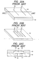
- a soluble resin layer 103 is formed on the substrate 102 on which the ink discharging energy generating elements (heat generating resistance bodies) 101 were formed, and, then, a coat resin layer 105 which constitutes the orifice plate later is coated by spin coating or the like. Thereafter, the soluble resin layer 103 is dissolved and the ink supply port 107 is formed in the substrate 102.
- the thin portion of the orifice plate 105 is subjected to concentrated stress, with the result that the orifice plate may be apt to be peeled from the substrate 102, reliability may be worsened and a service life of the liquid discharge recording head may be shortened. Further, since the ink discharged amount is determined by a distance (gap) between the heat generating resistance body 101 for generating the ink discharge energy and the front surface of the orifice plate 101, as shown in Figs.
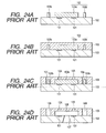
- a soluble resin layer 103 is formed on a substrate 102 on which a predetermined number of heat generating resistance bodies (electrical/thermal converting elements) 101 as ink discharging energy generating elements were arranged at predetermined positions.
- the soluble resin layer 103 includes not only a pattern 103a constituting an ink flow path but also a pattern 103b constituting a foundation encircling outer periphery of the ink flow path.
- the soluble resin layer 103 is coated, for example, by laminating of dry film or spin coating of resist and then is patterned, for example, by exposure and development by using ultraviolet ray (deep-UV light).
- polymethyl isopropenyl ketone such as ODUR-1010 manufactured by TOKYO OUKA KOGYO Co., Ltd.
- polymethyl isopropenyl ketone such as ODUR-1010 manufactured by TOKYO OUKA KOGYO Co., Ltd.
- a coat resin layer 105 is formed on the soluble resin layer 103 by spin coating or the like.
- the coat resin layer 105 forms a mountain shape with an apex corresponding to the pattern 103a gradually sloping down, thereby making the thickness of the coat resin layer uneven.
- Fig. 23B to 23D the coat resin layer 105 forms a mountain shape with an apex corresponding to the pattern 103a gradually sloping down, thereby making the thickness of the coat resin layer uneven.
- ink discharge ports 106 are formed in the coat resin layer 105, and an opening portion 104 is formed above and around the pattern 103b constituting the foundation. Formation of the ink discharge ports 106 and the opening portion 104 can be effected by exposure and development using ultraviolet ray (deep-UV light), for example. More concretely, after negative resist is coated by spin coating and is dried, by pattern-exposing and developing it, the ink discharge ports 106 and the opening portion 104 can be formed.
- ultraviolet ray deep-UV light
- the soluble resin layer 103 is dissolved to form the ink flow path 108 and a groove 109 encircling the ink flow path.
- the removal of the soluble resin layer 103 can be performed by effecting whole surface exposure using deep-UV light and then by effecting dissolution and drying, and, when ultrasonic treatment is effected upon dissolution, the resin layer 103 can be removed positively for a shorter time.
- a plurality of liquid discharging mechanisms shown in Fig. 24D are formed on the single substrate 102 by the aforementioned steps, and, after such mechanisms are completed, the substrate 102 is divided and cut by a dicing saw to form chips, and, after electrical connection for driving the heat generating resistance bodies is completed, a member such as an ink tank for supplying the ink is joined to the chip, thereby completing the liquid discharge recording head.
- the orifice plate 105 does not cover all of portions other than the ink discharge ports 106 and the electrical connections, it can be prevent that the substrate 102 is deformed due to stress generated by the hardening and/or temperature change of the orifice plate 105 and that the stress concentrates on edges of the orifice plate 105, i.e., wall portions of the ink flow path 108 thereby to cause peeling between the orifice plate and the substrate 102.
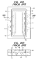
- Figs. 25A to 25C schematically show the liquid discharge recording head looked at from the above.
- a single array of the ink discharge ports 106 is disposed at each side of the ink supply port 107.
- Fig. 25C is an enlarged view of a portion encircled by a circle in Fig. 25B , for explaining stress components 110 acting on both sides of the groove 109 in detail.
- Fig. 25C there is the groove 109 at the center, and the stress components 110 act on edge portions of the groove in the orifice plate 105.
- the stress components 110 acts in the directions perpendicular to the edge portions of the orifice plate 105, the entire stress components 110 constitute the forces which try to peel the orifice plate 105 as they are. Since the greater the area and thickness of the orifice plate 105 the greater the stress components 110, in case of an orifice plate 105 having a greater length, the peeling is more apt to occur.
- Figs. 26A and 26B schematically show occurrence of such peeling. As shown in Figs. 26A and 26B , it can be seen that the peeling (peeled portions 111) occurs between the substrate 102 and the orifice plate 105 around the edge portions contacted with the groove 109.
- the present invention is made in consideration of the above-mentioned conventional drawbacks, and an object of the present invention is to provide a liquid discharge recording head of side shooter type in which peeling does not occur if the head becomes longer and which has good reliability, and a method for manufacturing such a head.
- the present invention provides a liquid discharge recording head comprising a substrate on which an energy generating element for generating liquid discharging energy is provided, and an orifice plate which is laminated with the substrate and in which a discharge port corresponding to the energy generating element is provided, and wherein a liquid droplet is discharged in a direction substantially perpendicular to surfaces of the substrate and the orifice plate, and further wherein a flow path is formed between the substrate and the orifice plate, and a groove encircling the flow path is formed in the orifice plate, and edge portions of the orifice plate contacted with the groove are formed as saw-shaped portions having a number of minute indentations.
- the indentations provided on the edge portion of the orifice plate contacted with the groove may be constituted by a combination of straight segments and curved segments, and each straight segment may not have the portion perpendicular to the direction of the stress acting on the edge portion and a tangential line to each curved segment may not have continuously the portion perpendicular to the direction of the stress acting on the edge portion.
- the portion of the orifice plate disposed outside of the groove may have a thickness smaller than those of other portions.
- the present invention provides a liquid discharge recording head comprising a substrate on which an energy generating element for generating liquid discharging energy is provided and an orifice plate which is laminated with the substrate and in which a discharge port corresponding to the energy generating element is provided, and wherein a liquid droplet is discharged in a direction substantially perpendicular to surfaces of the substrate and the orifice plate, and further wherein a flow path is formed between the substrate and the orifice plate, and the orifice plate has a hole array including a plurality of holes and encircling the flow path.
- a ceiling portion for the groove may be formed by remaining at least a part of a portion covering a space above the area where the pattern constituting the foundation is to be formed on the coat resin layer constituting the orifice plate.
- a predetermined number of ink discharging energy generating elements such as the heat generating resistance bodies (electrical/thermal converting elements) 1 are installed on the substrate 2 at predetermined positions.
- heat generating resistance bodies 1 are installed with density of 600 per one inch.
- the liquid discharge recording head manufactured in this way the small liquid droplet recording for realizing highly fine recording can be performed stably, and the stress acting on the wall portions of the ink flow path 8 can be reduced as small as possible, and the surface of the substrate 2 can be prevented from being damaged, and, as mentioned above, the peeling of the orifice plate 5 form the substrate 2 can be suppressed.
- a temperature/humidity cycle test was performed in a condition that the chip portion including the substrate 2 is capped by rubber. More concretely, the temperature/humidity cycle test was performed in the following manner. First of all, a temperature is constantly increased from 25°C to 65°C for 2 hours and 30 minutes while maintaining relative humidity to 95%, and, after the temperature is maintained to 65°C for 3 hours, the temperature is constantly decreased to 25°C for 2 hours and 30 minutes, and, thereafter, the temperature is constantly increased from 25°C to 65°C for 2 hours and 30 minutes again, and, after the temperature is maintained to 65°C for 3 hours, the temperature is constantly decreased to 25°C for 2 hour and 30 minutes again, and, then, after the temperature is maintained to 25°C for 1 hour and 30 minutes, the relative humidity is made to 0% and the temperature is made to -10°C and then this condition is maintained for 3 hours and 30 minutes, and, then, the relative humidity is made to 95% and the temperature is made to 25°C and
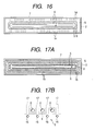
- Fig. 4 shows a liquid discharge recording head according to a second embodiment of the present invention.
- the same elements as those in the first embodiment are designated by the same reference numerals and explanation thereof will be omitted.
- Fig. 4 elements other than the substrate 2, orifice plate (coat resin layer) 5 and groove 9 are omitted from illustration.
- the edge portions of the orifices plate 5 contacted with the groove 9 are formed as saw-shaped portions having a more acute angle so that the angle ⁇ between the straight segment of each edge portion of the orifice plate 5 and the stress P becomes smaller than that in the first embodiment.
- the stress component P 2 of the stress P i.e., the force trying to peel the orifice plate 5 from the substrate 2 becomes smaller.
- Figs. 5A and 5B show a liquid discharge recording head according to a third embodiment of the present invention.
- the same elements as those in the first and second embodiments are designated by the same reference numerals and explanation thereof will be omitted.
- the edge portions of the orifice plate 5 contacted with the groove 9 are formed as rounded saw-shaped portions. That is to say, each top or peak of saw tooth is rounded or curved.
- the angle is continuously changed, so that the stress component (trying to generate the peeling) of the stress P acting on the edge portion is also smaller than the stress P. More concretely, as shown in Fig.
- a tangential line of the edge portion of the orifice plate 5 is inclined by an angle (90° - ⁇ 2 ) with respect to the stress.
- the stress P at the point X 2 can be divided into a tangential stress component P 3 and a normal stress component P 4 .
- Fig. 6 shows a liquid discharge recording head according to a fourth embodiment of the present invention.
- the same elements as those in the first to third embodiments are designated by the same reference numerals and explanation thereof will be omitted.
- the edge portions of the orifice plate 5 contacted with the groove 9 according to the fourth embodiment are formed as saw-shaped portions further rounded in comparison with the third embodiment. Also in the fourth embodiment, the stress components perpendicular to the edge portions of the orifice plate 5 are smaller than the stress P itself, with the result that the force trying to generate the peeling is smaller in comparison with the conventional liquid discharge recording heads.
- edge portion of the orifice plate 5 is constituted by the rounded saw-shaped portion, since there is no corner portion (which is a base point for the peeling in the straight edge portion), the peeling is more hard to be occur, thereby preventing a bad influence from affecting upon the discharging performance.
- Fig. 7 shows a liquid discharge recording head according to a fifth embodiment of the present invention.
- the same elements as those in the first to fourth embodiments are designated by the same reference numerals and explanation thereof will be omitted.
- an orifice plate portion (coat resin layer) 5 disposed outside of the groove 9 is divided into plural regions by slits 12.
- the number of slits 12 is eight, so that the orifice plate portion 5 disposed outside of the groove 9 is divided into eight regions. Accordingly, the stress acting on the orifice plate portion 5 is also divided into eight, and the volume of the orifice plate becomes smaller here. Thus, the stress (including the force trying to generate the peeling) acting on each of the divided regions of the orifice plate 5 becomes smaller in comparison with the conventional cases.
- the peeling between the substrate 2 and the orifice plate 5 is hard to be occur or at least the peeling is hard to be progressed. Further, deformation of the substrate 2 due to the stress becomes smaller.
- the groove 9 is formed as a saw-shaped portion was illustrated, it is important that the orifice plate is divided as mentioned above, and it is more preferable that such division in combined with the saw-shaped groove 9.
- Figs. 8 to 10 show liquid discharge recording heads according to sixth to eighth embodiments of the present invention. Incidentally, the same elements as those in the first to fifth embodiments are designated by the same reference numerals and explanation thereof will be omitted.
- indentation configurations of the edge portions of the orifice plate 5 contacted with the groove 9 are altered in various ways as described in the second to fourth embodiments.
- stress P acting on the edge portion (ink flow path wall 17) of the orifice plate 5 is divided into a stress component P 5 along the edge portion and a stress component P 6 perpendicular to the edge portion, and, since the force trying to generate the peeling is merely the stress component P 6 , the force trying to generate the peeling becomes smaller in comparison with the conventional cases.
- the edge portions are formed as the saw-shaped portions at the thin side wall portions of the ink flow path 8 where the peeling is apt to occur, although the effect for preventing the peeling is enhanced, as shown in Fig. 12 , at the entire contour of the ink flow path 8, the edge portions (ink flow path walls 17) of the orifice plate 5 contacted with the ink flow path 8 may be formed as rounded saw-shaped portions as is in the third and fourth embodiments. Also in this embodiment, it is preferable that the saw-shaped groove 9 as explained in connection with the first embodiment is added.
- Figs. 13A and 13B show a liquid discharge recording head according to a tenth embodiment of the present invention.
- the same elements as those in the first to ninth embodiments are designated by the same reference numerals and explanation thereof will be omitted.
- the through-hole 13 is cylindrical, since there is no corner portion (which is a base point for the peeling in the straight edge portion), the peeling is more hard to be occur, thereby preventing a bad influence from affecting upon the discharging performance. Also in this embodiment, it is preferable that the saw-shaped groove 9 as explained in connection with the first embodiment is added.
- each recessed groove 14 is formed obliquely from the surface of the orifice plate 5 to the surface of the substrate 2 and contributes to reduce the volume of the orifice plate 5, and, since the coat resin constituting the orifice plate acts to expand and contract the recessed grooves 14 slightly, the expansion and contraction of the orifice plate 5 are absorbed by the deformation of the recessed grooves (or wall surfaces of the recessed grooves 14), thereby relieving the stress. Accordingly, it is said that the peeling of the orifice plate 5 is hard to occur or at least the peeling is hard to be progressed. Further, the deformation of the substrate 2 due to the stress is small.
Landscapes
- Engineering & Computer Science (AREA)
- Manufacturing & Machinery (AREA)
- Physics & Mathematics (AREA)
- Geometry (AREA)
- Particle Formation And Scattering Control In Inkjet Printers (AREA)
Applications Claiming Priority (2)
| Application Number | Priority Date | Filing Date | Title |
|---|---|---|---|
| JP2001276757A JP4731763B2 (ja) | 2001-09-12 | 2001-09-12 | 液体噴射記録ヘッドおよびその製造方法 |
| EP02020228A EP1293343B1 (de) | 2001-09-12 | 2002-09-10 | Flüssigkeitsausstosskopf und dazugehöriges Herstellungsverfahren |
Related Parent Applications (2)
| Application Number | Title | Priority Date | Filing Date |
|---|---|---|---|
| EP02020228A Division EP1293343B1 (de) | 2001-09-12 | 2002-09-10 | Flüssigkeitsausstosskopf und dazugehöriges Herstellungsverfahren |
| EP02020228.9 Division | 2002-09-10 |
Publications (3)
| Publication Number | Publication Date |
|---|---|
| EP1950040A2 true EP1950040A2 (de) | 2008-07-30 |
| EP1950040A3 EP1950040A3 (de) | 2008-08-20 |
| EP1950040B1 EP1950040B1 (de) | 2012-06-06 |
Family
ID=19101412
Family Applications (2)
| Application Number | Title | Priority Date | Filing Date |
|---|---|---|---|
| EP02020228A Expired - Lifetime EP1293343B1 (de) | 2001-09-12 | 2002-09-10 | Flüssigkeitsausstosskopf und dazugehöriges Herstellungsverfahren |
| EP08154340A Expired - Lifetime EP1950040B1 (de) | 2001-09-12 | 2002-09-10 | Flüssigkeitsausstoß-Aufzeichnungskopf |
Family Applications Before (1)
| Application Number | Title | Priority Date | Filing Date |
|---|---|---|---|
| EP02020228A Expired - Lifetime EP1293343B1 (de) | 2001-09-12 | 2002-09-10 | Flüssigkeitsausstosskopf und dazugehöriges Herstellungsverfahren |
Country Status (7)
| Country | Link |
|---|---|
| US (1) | US6799831B2 (de) |
| EP (2) | EP1293343B1 (de) |
| JP (1) | JP4731763B2 (de) |
| KR (1) | KR100506436B1 (de) |
| CN (1) | CN1241743C (de) |
| AT (1) | ATE412523T1 (de) |
| DE (1) | DE60229601D1 (de) |
Families Citing this family (45)
| Publication number | Priority date | Publication date | Assignee | Title |
|---|---|---|---|---|
| JP4731763B2 (ja) | 2001-09-12 | 2011-07-27 | キヤノン株式会社 | 液体噴射記録ヘッドおよびその製造方法 |
| JP2004001490A (ja) | 2002-04-23 | 2004-01-08 | Canon Inc | インクジェットヘッド |
| JP2005022088A (ja) * | 2003-06-30 | 2005-01-27 | Brother Ind Ltd | 薄板部材の積層接着構造及びインクジェットヘッド |
| CN1317736C (zh) * | 2003-08-14 | 2007-05-23 | 明基电通股份有限公司 | 单片流体喷射装置的制作方法 |
| WO2005065294A2 (en) | 2003-12-30 | 2005-07-21 | Dimatix, Inc. | Drop ejection assembly |
| US7410241B2 (en) * | 2004-09-13 | 2008-08-12 | Canon Kabushiki Kaisha | Ink jet head, ink jet printer and method for manufacturing ink jet head |
| TWI289511B (en) * | 2004-11-22 | 2007-11-11 | Canon Kk | Method of manufacturing liquid discharge head, and liquid discharge head |
| US7914127B2 (en) * | 2005-05-31 | 2011-03-29 | Telecom Italia S.P.A. | Nozzle plate for an ink jet print head comprising stress relieving elements |
| JP2007076015A (ja) * | 2005-09-12 | 2007-03-29 | Sony Corp | 液体吐出ヘッド |
| TWI306812B (en) * | 2005-10-17 | 2009-03-01 | Canon Kk | Liquid discharge head and manufacturing method of the same |
| US7523553B2 (en) * | 2006-02-02 | 2009-04-28 | Canon Kabushiki Kaisha | Method of manufacturing ink jet recording head |
| JP5188158B2 (ja) * | 2006-12-15 | 2013-04-24 | キヤノン株式会社 | インクジェット記録ヘッドの製造方法 |
| KR101406792B1 (ko) * | 2007-08-13 | 2014-06-13 | 삼성전자주식회사 | 포토리소그래피 공정을 이용한 감광성 에폭시 구조물의제조방법 및 이를 이용한 잉크젯 프린트헤드의 제조방법 |
| JP5038110B2 (ja) * | 2007-11-27 | 2012-10-03 | キヤノン株式会社 | インクジェット記録ヘッドおよびインクジェット記録装置 |
| JP5183187B2 (ja) * | 2007-12-14 | 2013-04-17 | キヤノン株式会社 | 液体吐出ヘッド |
| JP5328380B2 (ja) | 2008-01-23 | 2013-10-30 | キヤノン株式会社 | 液体吐出ヘッド及び記録装置 |
| JP5312009B2 (ja) | 2008-01-23 | 2013-10-09 | キヤノン株式会社 | 液体噴射記録ヘッド |
| JP5511191B2 (ja) | 2008-01-28 | 2014-06-04 | キヤノン株式会社 | 液体吐出ヘッド、液体吐出ヘッドの製造方法および構造体の形成方法 |
| JP5288831B2 (ja) * | 2008-02-27 | 2013-09-11 | キヤノン株式会社 | インクジェット記録ヘッドの製造方法 |
| JP5322719B2 (ja) * | 2008-03-24 | 2013-10-23 | キヤノン株式会社 | インクジェット記録ヘッド |
| JP5294720B2 (ja) * | 2008-06-17 | 2013-09-18 | キヤノン株式会社 | インクジェット記録ヘッド |
| EP2147791A1 (de) * | 2008-07-22 | 2010-01-27 | Océ-Technologies B.V. | Herstellungsverfahren für eine Tröpfchenausstoßvorrichtung und Tröpfchenausstoßvorrichtung |
| JP5188308B2 (ja) | 2008-07-29 | 2013-04-24 | キヤノン株式会社 | インクジェット記録ヘッド |
| JP5132463B2 (ja) * | 2008-07-29 | 2013-01-30 | キヤノン株式会社 | 記録ヘッド |
| US8388099B2 (en) * | 2009-07-22 | 2013-03-05 | Canon Kabushiki Kaisha | Ink jet recording head |
| US8342659B2 (en) | 2009-08-25 | 2013-01-01 | Canon Kabushiki Kaisha | Liquid discharge head and method for manufacturing the same |
| JP5596954B2 (ja) * | 2009-10-08 | 2014-09-24 | キヤノン株式会社 | 液体供給部材、液体供給部材の製造方法及び液体吐出ヘッドの製造方法 |
| JP5393423B2 (ja) * | 2009-12-10 | 2014-01-22 | キヤノン株式会社 | インク吐出ヘッド及びその製造方法 |
| US8765498B2 (en) * | 2010-05-19 | 2014-07-01 | Canon Kabushiki Kaisha | Method of manufacturing liquid discharge head substrate, method of manufacturing liquid discharge head, and method of manufacturing liquid discharge head assembly |
| JP5106601B2 (ja) * | 2010-08-26 | 2012-12-26 | キヤノン株式会社 | 液体吐出ヘッド用基板の製造方法、液体吐出ヘッドの製造方法、及び液体吐出ヘッド用基板の検査方法 |
| JP5865019B2 (ja) * | 2010-11-17 | 2016-02-17 | キヤノン株式会社 | 液滴吐出ヘッドおよびその製造方法 |
| US20120306047A1 (en) * | 2011-06-06 | 2012-12-06 | Shenzhen China Star Optoelectronics Technology Co. Ltd. | Chip-on-film structure for liquid crystal panel |
| JP5911264B2 (ja) | 2011-11-01 | 2016-04-27 | キヤノン株式会社 | 液体吐出ヘッドの製造方法 |
| JP6120645B2 (ja) | 2012-04-18 | 2017-04-26 | キヤノン株式会社 | 液体吐出ヘッド |
| JP2013240990A (ja) * | 2012-04-27 | 2013-12-05 | Canon Inc | 液体吐出ヘッドおよびその製造方法 |
| JP6021415B2 (ja) * | 2012-04-27 | 2016-11-09 | キヤノン株式会社 | 液体吐出ヘッド、および記録装置 |
| JP6180143B2 (ja) * | 2013-03-22 | 2017-08-16 | キヤノン株式会社 | 液体吐出ヘッドの製造方法 |
| JP2014233960A (ja) * | 2013-06-05 | 2014-12-15 | キヤノン株式会社 | 流路構成体および流路構成体の製造方法 |
| US9114614B2 (en) * | 2013-06-05 | 2015-08-25 | Canon Kabushiki Kaisha | Liquid ejection head |
| US9352560B2 (en) | 2013-06-28 | 2016-05-31 | Hewlett-Packard Development Company, L.P. | Printhead structure |
| JP6727842B2 (ja) * | 2015-03-04 | 2020-07-22 | キヤノン株式会社 | 構造体の製造方法 |
| JP6961978B2 (ja) * | 2017-03-30 | 2021-11-05 | ブラザー工業株式会社 | 液滴吐出ヘッド |
| JP7652641B2 (ja) | 2021-06-25 | 2025-03-27 | キヤノン株式会社 | 液体吐出ヘッド |
| JP7825980B2 (ja) | 2021-11-29 | 2026-03-09 | キヤノン株式会社 | 液体吐出装置 |
| US12576642B2 (en) * | 2022-11-17 | 2026-03-17 | Ricoh Company, Ltd. | Liquid discharge head, liquid discharge module, and liquid discharge apparatus |
Citations (7)
| Publication number | Priority date | Publication date | Assignee | Title |
|---|---|---|---|---|
| JPS62234941A (ja) | 1986-04-02 | 1987-10-15 | Yokogawa Hewlett Packard Ltd | インクジエツトプリントヘツドの製造方法 |
| JPH0410942A (ja) | 1990-04-27 | 1992-01-16 | Canon Inc | 液体噴射方法および該方法を用いた記録装置 |
| JPH0410941A (ja) | 1990-04-27 | 1992-01-16 | Canon Inc | 液滴噴射方法及び該方法を用いた記録装置 |
| JPH0410940A (ja) | 1990-04-27 | 1992-01-16 | Canon Inc | 液体噴射方法および該方法を用いた記録装置 |
| JPH10157150A (ja) | 1996-12-05 | 1998-06-16 | Canon Inc | 液体噴射記録ヘッドの製造方法および液体噴射記録ヘッドを製造するための基板 |
| JPH11138817A (ja) | 1997-11-13 | 1999-05-25 | Canon Inc | 液体噴射ヘッドおよびその製造方法 |
| EP1293343A2 (de) | 2001-09-12 | 2003-03-19 | Canon Kabushiki Kaisha | Flüssigkeitsausstosskopf und dazugehöriges Herstellungsverfahren |
Family Cites Families (25)
| Publication number | Priority date | Publication date | Assignee | Title |
|---|---|---|---|---|
| JPS58220754A (ja) | 1982-06-18 | 1983-12-22 | Canon Inc | インクジエツト記録ヘツド |
| JPS58220756A (ja) | 1982-06-18 | 1983-12-22 | Canon Inc | インクジエツト記録ヘツドの製造方法 |
| JPS5919168A (ja) | 1982-07-26 | 1984-01-31 | Canon Inc | インクジエツト記録ヘツド |
| JPH0643129B2 (ja) | 1984-03-01 | 1994-06-08 | キヤノン株式会社 | インクジェット記録ヘッド |
| ES2087890T3 (es) | 1989-03-24 | 1996-08-01 | Canon Kk | Proceso para la fabricacion de un cabezal para la impresion por chorros de tinta. |
| DE69126996T2 (de) | 1990-04-27 | 1998-02-19 | Canon Kk | Aufzeichnungsverfahren und -gerät |
| JPH0412859A (ja) | 1990-04-28 | 1992-01-17 | Canon Inc | 液体噴射方法、該方法を用いた記録ヘッド及び該方法を用いた記録装置 |
| JP3351436B2 (ja) | 1991-08-21 | 2002-11-25 | セイコーエプソン株式会社 | 細孔を有する2部材の接着用シ−ト材 |
| US5685074A (en) | 1992-04-02 | 1997-11-11 | Hewlett-Packard Company | Method of forming an inkjet printhead with trench and backward peninsulas |
| JP3290495B2 (ja) | 1992-04-21 | 2002-06-10 | キヤノン株式会社 | インクジェット記録ヘッドの製造方法 |
| EP0573014B1 (de) | 1992-06-04 | 1998-10-28 | Canon Kabushiki Kaisha | Tintenstrahlkopfherstellungsverfahren, nach dem Verfahren hergestellter Tintenstrahlkopf und Tintenstrahlgerät damit versehen |
| US5896150A (en) | 1992-11-25 | 1999-04-20 | Seiko Epson Corporation | Ink-jet type recording head |
| JPH06190307A (ja) * | 1992-12-25 | 1994-07-12 | Ricoh Co Ltd | インクジェットヘッドのノズル板 |
| US6155677A (en) | 1993-11-26 | 2000-12-05 | Canon Kabushiki Kaisha | Ink jet recording head, an ink jet unit and an ink jet apparatus using said recording head |
| JPH0858101A (ja) * | 1994-06-13 | 1996-03-05 | Canon Inc | インクジェット記録ヘッド及びこれを搭載するインクジェット記録装置 |
| JPH08142327A (ja) * | 1994-11-16 | 1996-06-04 | Canon Inc | インクジェット記録装置の記録ヘッド |
| JP3570447B2 (ja) | 1994-12-21 | 2004-09-29 | セイコーエプソン株式会社 | 積層型インクジェット式記録ヘッド、及びその製造方法、及び記録装置 |
| JP3229146B2 (ja) | 1994-12-28 | 2001-11-12 | キヤノン株式会社 | 液体噴射ヘッドおよびその製造方法 |
| US6135586A (en) | 1995-10-31 | 2000-10-24 | Hewlett-Packard Company | Large area inkjet printhead |
| US6220697B1 (en) | 1996-08-30 | 2001-04-24 | Canon Kabushiki Kaisha | Ink jet recording head and ink jet recording apparatus having such head |
| US5988786A (en) * | 1997-06-30 | 1999-11-23 | Hewlett-Packard Company | Articulated stress relief of an orifice membrane |
| JPH1148480A (ja) * | 1997-08-01 | 1999-02-23 | Canon Inc | インクジェット記録ヘッド |
| JP2000108360A (ja) * | 1998-10-02 | 2000-04-18 | Sony Corp | プリントヘッドの製造方法 |
| EP1020291A3 (de) * | 1999-01-18 | 2001-04-11 | Canon Kabushiki Kaisha | Flüssigkeitsausstosskopf und Verfahren zur Herstellung desselben |
| US6586112B1 (en) * | 2000-08-01 | 2003-07-01 | Hewlett-Packard Company | Mandrel and orifice plates electroformed using the same |
-
2001
- 2001-09-12 JP JP2001276757A patent/JP4731763B2/ja not_active Expired - Fee Related
-
2002
- 2002-09-09 US US10/237,103 patent/US6799831B2/en not_active Expired - Lifetime
- 2002-09-10 EP EP02020228A patent/EP1293343B1/de not_active Expired - Lifetime
- 2002-09-10 DE DE60229601T patent/DE60229601D1/de not_active Expired - Lifetime
- 2002-09-10 AT AT02020228T patent/ATE412523T1/de not_active IP Right Cessation
- 2002-09-10 EP EP08154340A patent/EP1950040B1/de not_active Expired - Lifetime
- 2002-09-11 KR KR10-2002-0054803A patent/KR100506436B1/ko not_active Expired - Fee Related
- 2002-09-12 CN CNB021316953A patent/CN1241743C/zh not_active Expired - Fee Related
Patent Citations (7)
| Publication number | Priority date | Publication date | Assignee | Title |
|---|---|---|---|---|
| JPS62234941A (ja) | 1986-04-02 | 1987-10-15 | Yokogawa Hewlett Packard Ltd | インクジエツトプリントヘツドの製造方法 |
| JPH0410942A (ja) | 1990-04-27 | 1992-01-16 | Canon Inc | 液体噴射方法および該方法を用いた記録装置 |
| JPH0410941A (ja) | 1990-04-27 | 1992-01-16 | Canon Inc | 液滴噴射方法及び該方法を用いた記録装置 |
| JPH0410940A (ja) | 1990-04-27 | 1992-01-16 | Canon Inc | 液体噴射方法および該方法を用いた記録装置 |
| JPH10157150A (ja) | 1996-12-05 | 1998-06-16 | Canon Inc | 液体噴射記録ヘッドの製造方法および液体噴射記録ヘッドを製造するための基板 |
| JPH11138817A (ja) | 1997-11-13 | 1999-05-25 | Canon Inc | 液体噴射ヘッドおよびその製造方法 |
| EP1293343A2 (de) | 2001-09-12 | 2003-03-19 | Canon Kabushiki Kaisha | Flüssigkeitsausstosskopf und dazugehöriges Herstellungsverfahren |
Also Published As
| Publication number | Publication date |
|---|---|
| EP1950040B1 (de) | 2012-06-06 |
| JP4731763B2 (ja) | 2011-07-27 |
| EP1293343A3 (de) | 2003-09-24 |
| KR100506436B1 (ko) | 2005-08-11 |
| US20030048328A1 (en) | 2003-03-13 |
| US6799831B2 (en) | 2004-10-05 |
| EP1950040A3 (de) | 2008-08-20 |
| EP1293343A2 (de) | 2003-03-19 |
| EP1293343B1 (de) | 2008-10-29 |
| CN1404995A (zh) | 2003-03-26 |
| CN1241743C (zh) | 2006-02-15 |
| KR20030023512A (ko) | 2003-03-19 |
| DE60229601D1 (de) | 2008-12-11 |
| ATE412523T1 (de) | 2008-11-15 |
| JP2003080717A (ja) | 2003-03-19 |
Similar Documents
| Publication | Publication Date | Title |
|---|---|---|
| EP1950040B1 (de) | Flüssigkeitsausstoß-Aufzeichnungskopf | |
| JP7250553B2 (ja) | 液体吐出ヘッドの製造方法 | |
| US8052251B2 (en) | Ink jet recording head | |
| EP0739736B1 (de) | Tintenstrahldruckkopf und Apparat zum Aufzeichnen von Bildern | |
| US20020196313A1 (en) | Liquid discharge head | |
| JP2010100028A (ja) | 液体吐出ヘッド、液体吐出ヘッドの製造方法および構造体の形成方法 | |
| JPH09314841A (ja) | インクジェット記録ヘッドとその製造方法 | |
| US6109738A (en) | Ink jet print head and a method of manufacturing the same | |
| KR20030070618A (ko) | 잉크젯 프린트헤드에서의 노즐의 보호 | |
| US8091233B2 (en) | Method of manufacturing liquid discharge head | |
| JP3413082B2 (ja) | 液体噴射ヘッドおよびその製造方法 | |
| JP7134831B2 (ja) | 液体吐出ヘッドの製造方法 | |
| US20060038851A1 (en) | Micro-fluid ejection devices and method therefor | |
| JP5661357B2 (ja) | インクジェット記録ヘッド | |
| JP7652641B2 (ja) | 液体吐出ヘッド | |
| JP2001179963A (ja) | インクジェットヘッド | |
| JP3719110B2 (ja) | インクジェットプリンタヘッドの製造方法 | |
| JP2007261169A (ja) | 液体噴射ヘッド | |
| CN1311973C (zh) | 热泡式喷墨打印头及其制作过程 | |
| JP2001158102A (ja) | インクジェットプリンタヘッドの製造方法 | |
| JP4213268B2 (ja) | インクジェットヘッド | |
| US20070085881A1 (en) | Methods for improved micro-fluid ejection devices | |
| CN110856997B (zh) | 液体排出头和液体排出头的制造方法 | |
| JP3282428B2 (ja) | インクジェット記録ヘッド | |
| JP2001129998A (ja) | インクジェットプリンタヘッド及びその製造方法 |
Legal Events
| Date | Code | Title | Description |
|---|---|---|---|
| PUAI | Public reference made under article 153(3) epc to a published international application that has entered the european phase |
Free format text: ORIGINAL CODE: 0009012 |
|
| PUAL | Search report despatched |
Free format text: ORIGINAL CODE: 0009013 |
|
| AC | Divisional application: reference to earlier application |
Ref document number: 1293343 Country of ref document: EP Kind code of ref document: P |
|
| AK | Designated contracting states |
Kind code of ref document: A2 Designated state(s): AT BE BG CH CY CZ DE DK EE ES FI FR GB GR IE IT LI LU MC NL PT SE SK TR |
|
| AK | Designated contracting states |
Kind code of ref document: A3 Designated state(s): AT BE BG CH CY CZ DE DK EE ES FI FR GB GR IE IT LI LU MC NL PT SE SK TR |
|
| RIC1 | Information provided on ipc code assigned before grant |
Ipc: B41J 2/14 20060101AFI20080620BHEP Ipc: B41J 2/16 20060101ALI20080714BHEP |
|
| 17P | Request for examination filed |
Effective date: 20090220 |
|
| AKX | Designation fees paid |
Designated state(s): DE FR GB IT |
|
| 17Q | First examination report despatched |
Effective date: 20100728 |
|
| GRAP | Despatch of communication of intention to grant a patent |
Free format text: ORIGINAL CODE: EPIDOSNIGR1 |
|
| RTI1 | Title (correction) |
Free format text: LIQUID DISCHARGE HEAD |
|
| GRAS | Grant fee paid |
Free format text: ORIGINAL CODE: EPIDOSNIGR3 |
|
| RIN1 | Information on inventor provided before grant (corrected) |
Inventor name: YAMAMOTO, HIROYUKI Inventor name: KURIHARA, YOSHIAKI Inventor name: YABE, KENJI Inventor name: INAMOTO, TADAYOSHI Inventor name: TERAI, HARUHIKO |
|
| GRAA | (expected) grant |
Free format text: ORIGINAL CODE: 0009210 |
|
| AC | Divisional application: reference to earlier application |
Ref document number: 1293343 Country of ref document: EP Kind code of ref document: P |
|
| AK | Designated contracting states |
Kind code of ref document: B1 Designated state(s): DE FR GB IT |
|
| REG | Reference to a national code |
Ref country code: GB Ref legal event code: FG4D |
|
| REG | Reference to a national code |
Ref country code: DE Ref legal event code: R096 Ref document number: 60243096 Country of ref document: DE Effective date: 20120802 |
|
| PG25 | Lapsed in a contracting state [announced via postgrant information from national office to epo] |
Ref country code: IT Free format text: LAPSE BECAUSE OF FAILURE TO SUBMIT A TRANSLATION OF THE DESCRIPTION OR TO PAY THE FEE WITHIN THE PRESCRIBED TIME-LIMIT Effective date: 20120606 |
|
| PLBE | No opposition filed within time limit |
Free format text: ORIGINAL CODE: 0009261 |
|
| STAA | Information on the status of an ep patent application or granted ep patent |
Free format text: STATUS: NO OPPOSITION FILED WITHIN TIME LIMIT |
|
| 26N | No opposition filed |
Effective date: 20130307 |
|
| REG | Reference to a national code |
Ref country code: FR Ref legal event code: ST Effective date: 20130531 |
|
| REG | Reference to a national code |
Ref country code: DE Ref legal event code: R097 Ref document number: 60243096 Country of ref document: DE Effective date: 20130307 |
|
| PG25 | Lapsed in a contracting state [announced via postgrant information from national office to epo] |
Ref country code: FR Free format text: LAPSE BECAUSE OF NON-PAYMENT OF DUE FEES Effective date: 20121001 |
|
| PGFP | Annual fee paid to national office [announced via postgrant information from national office to epo] |
Ref country code: GB Payment date: 20150922 Year of fee payment: 14 Ref country code: DE Payment date: 20150930 Year of fee payment: 14 |
|
| REG | Reference to a national code |
Ref country code: DE Ref legal event code: R119 Ref document number: 60243096 Country of ref document: DE |
|
| GBPC | Gb: european patent ceased through non-payment of renewal fee |
Effective date: 20160910 |
|
| PG25 | Lapsed in a contracting state [announced via postgrant information from national office to epo] |
Ref country code: GB Free format text: LAPSE BECAUSE OF NON-PAYMENT OF DUE FEES Effective date: 20160910 Ref country code: DE Free format text: LAPSE BECAUSE OF NON-PAYMENT OF DUE FEES Effective date: 20170401 |