EP1944185A2 - Fahrzeugantriebsvorrichtung - Google Patents
Fahrzeugantriebsvorrichtung Download PDFInfo
- Publication number
- EP1944185A2 EP1944185A2 EP08000501A EP08000501A EP1944185A2 EP 1944185 A2 EP1944185 A2 EP 1944185A2 EP 08000501 A EP08000501 A EP 08000501A EP 08000501 A EP08000501 A EP 08000501A EP 1944185 A2 EP1944185 A2 EP 1944185A2
- Authority
- EP
- European Patent Office
- Prior art keywords
- electric motor
- differential gear
- driving force
- vehicle
- shaft
- Prior art date
- Legal status (The legal status is an assumption and is not a legal conclusion. Google has not performed a legal analysis and makes no representation as to the accuracy of the status listed.)
- Withdrawn
Links
Images


Classifications
-
- B—PERFORMING OPERATIONS; TRANSPORTING
- B60—VEHICLES IN GENERAL
- B60K—ARRANGEMENT OR MOUNTING OF PROPULSION UNITS OR OF TRANSMISSIONS IN VEHICLES; ARRANGEMENT OR MOUNTING OF PLURAL DIVERSE PRIME-MOVERS IN VEHICLES; AUXILIARY DRIVES FOR VEHICLES; INSTRUMENTATION OR DASHBOARDS FOR VEHICLES; ARRANGEMENTS IN CONNECTION WITH COOLING, AIR INTAKE, GAS EXHAUST OR FUEL SUPPLY OF PROPULSION UNITS IN VEHICLES
- B60K6/00—Arrangement or mounting of plural diverse prime-movers for mutual or common propulsion, e.g. hybrid propulsion systems comprising electric motors and internal combustion engines ; Control systems therefor, i.e. systems controlling two or more prime movers, or controlling one of these prime movers and any of the transmission, drive or drive units Informative references: mechanical gearings with secondary electric drive F16H3/72; arrangements for handling mechanical energy structurally associated with the dynamo-electric machine H02K7/00; machines comprising structurally interrelated motor and generator parts H02K51/00; dynamo-electric machines not otherwise provided for in H02K see H02K99/00
- B60K6/20—Arrangement or mounting of plural diverse prime-movers for mutual or common propulsion, e.g. hybrid propulsion systems comprising electric motors and internal combustion engines ; Control systems therefor, i.e. systems controlling two or more prime movers, or controlling one of these prime movers and any of the transmission, drive or drive units Informative references: mechanical gearings with secondary electric drive F16H3/72; arrangements for handling mechanical energy structurally associated with the dynamo-electric machine H02K7/00; machines comprising structurally interrelated motor and generator parts H02K51/00; dynamo-electric machines not otherwise provided for in H02K see H02K99/00 the prime-movers consisting of electric motors and internal combustion engines, e.g. HEVs
- B60K6/42—Arrangement or mounting of plural diverse prime-movers for mutual or common propulsion, e.g. hybrid propulsion systems comprising electric motors and internal combustion engines ; Control systems therefor, i.e. systems controlling two or more prime movers, or controlling one of these prime movers and any of the transmission, drive or drive units Informative references: mechanical gearings with secondary electric drive F16H3/72; arrangements for handling mechanical energy structurally associated with the dynamo-electric machine H02K7/00; machines comprising structurally interrelated motor and generator parts H02K51/00; dynamo-electric machines not otherwise provided for in H02K see H02K99/00 the prime-movers consisting of electric motors and internal combustion engines, e.g. HEVs characterised by the architecture of the hybrid electric vehicle
- B60K6/48—Parallel type
-
- B—PERFORMING OPERATIONS; TRANSPORTING
- B60—VEHICLES IN GENERAL
- B60K—ARRANGEMENT OR MOUNTING OF PROPULSION UNITS OR OF TRANSMISSIONS IN VEHICLES; ARRANGEMENT OR MOUNTING OF PLURAL DIVERSE PRIME-MOVERS IN VEHICLES; AUXILIARY DRIVES FOR VEHICLES; INSTRUMENTATION OR DASHBOARDS FOR VEHICLES; ARRANGEMENTS IN CONNECTION WITH COOLING, AIR INTAKE, GAS EXHAUST OR FUEL SUPPLY OF PROPULSION UNITS IN VEHICLES
- B60K6/00—Arrangement or mounting of plural diverse prime-movers for mutual or common propulsion, e.g. hybrid propulsion systems comprising electric motors and internal combustion engines ; Control systems therefor, i.e. systems controlling two or more prime movers, or controlling one of these prime movers and any of the transmission, drive or drive units Informative references: mechanical gearings with secondary electric drive F16H3/72; arrangements for handling mechanical energy structurally associated with the dynamo-electric machine H02K7/00; machines comprising structurally interrelated motor and generator parts H02K51/00; dynamo-electric machines not otherwise provided for in H02K see H02K99/00
- B60K6/20—Arrangement or mounting of plural diverse prime-movers for mutual or common propulsion, e.g. hybrid propulsion systems comprising electric motors and internal combustion engines ; Control systems therefor, i.e. systems controlling two or more prime movers, or controlling one of these prime movers and any of the transmission, drive or drive units Informative references: mechanical gearings with secondary electric drive F16H3/72; arrangements for handling mechanical energy structurally associated with the dynamo-electric machine H02K7/00; machines comprising structurally interrelated motor and generator parts H02K51/00; dynamo-electric machines not otherwise provided for in H02K see H02K99/00 the prime-movers consisting of electric motors and internal combustion engines, e.g. HEVs
- B60K6/22—Arrangement or mounting of plural diverse prime-movers for mutual or common propulsion, e.g. hybrid propulsion systems comprising electric motors and internal combustion engines ; Control systems therefor, i.e. systems controlling two or more prime movers, or controlling one of these prime movers and any of the transmission, drive or drive units Informative references: mechanical gearings with secondary electric drive F16H3/72; arrangements for handling mechanical energy structurally associated with the dynamo-electric machine H02K7/00; machines comprising structurally interrelated motor and generator parts H02K51/00; dynamo-electric machines not otherwise provided for in H02K see H02K99/00 the prime-movers consisting of electric motors and internal combustion engines, e.g. HEVs characterised by apparatus, components or means specially adapted for HEVs
- B60K6/26—Arrangement or mounting of plural diverse prime-movers for mutual or common propulsion, e.g. hybrid propulsion systems comprising electric motors and internal combustion engines ; Control systems therefor, i.e. systems controlling two or more prime movers, or controlling one of these prime movers and any of the transmission, drive or drive units Informative references: mechanical gearings with secondary electric drive F16H3/72; arrangements for handling mechanical energy structurally associated with the dynamo-electric machine H02K7/00; machines comprising structurally interrelated motor and generator parts H02K51/00; dynamo-electric machines not otherwise provided for in H02K see H02K99/00 the prime-movers consisting of electric motors and internal combustion engines, e.g. HEVs characterised by apparatus, components or means specially adapted for HEVs characterised by the motors or the generators
-
- B—PERFORMING OPERATIONS; TRANSPORTING
- B60—VEHICLES IN GENERAL
- B60K—ARRANGEMENT OR MOUNTING OF PROPULSION UNITS OR OF TRANSMISSIONS IN VEHICLES; ARRANGEMENT OR MOUNTING OF PLURAL DIVERSE PRIME-MOVERS IN VEHICLES; AUXILIARY DRIVES FOR VEHICLES; INSTRUMENTATION OR DASHBOARDS FOR VEHICLES; ARRANGEMENTS IN CONNECTION WITH COOLING, AIR INTAKE, GAS EXHAUST OR FUEL SUPPLY OF PROPULSION UNITS IN VEHICLES
- B60K6/00—Arrangement or mounting of plural diverse prime-movers for mutual or common propulsion, e.g. hybrid propulsion systems comprising electric motors and internal combustion engines ; Control systems therefor, i.e. systems controlling two or more prime movers, or controlling one of these prime movers and any of the transmission, drive or drive units Informative references: mechanical gearings with secondary electric drive F16H3/72; arrangements for handling mechanical energy structurally associated with the dynamo-electric machine H02K7/00; machines comprising structurally interrelated motor and generator parts H02K51/00; dynamo-electric machines not otherwise provided for in H02K see H02K99/00
- B60K6/20—Arrangement or mounting of plural diverse prime-movers for mutual or common propulsion, e.g. hybrid propulsion systems comprising electric motors and internal combustion engines ; Control systems therefor, i.e. systems controlling two or more prime movers, or controlling one of these prime movers and any of the transmission, drive or drive units Informative references: mechanical gearings with secondary electric drive F16H3/72; arrangements for handling mechanical energy structurally associated with the dynamo-electric machine H02K7/00; machines comprising structurally interrelated motor and generator parts H02K51/00; dynamo-electric machines not otherwise provided for in H02K see H02K99/00 the prime-movers consisting of electric motors and internal combustion engines, e.g. HEVs
- B60K6/22—Arrangement or mounting of plural diverse prime-movers for mutual or common propulsion, e.g. hybrid propulsion systems comprising electric motors and internal combustion engines ; Control systems therefor, i.e. systems controlling two or more prime movers, or controlling one of these prime movers and any of the transmission, drive or drive units Informative references: mechanical gearings with secondary electric drive F16H3/72; arrangements for handling mechanical energy structurally associated with the dynamo-electric machine H02K7/00; machines comprising structurally interrelated motor and generator parts H02K51/00; dynamo-electric machines not otherwise provided for in H02K see H02K99/00 the prime-movers consisting of electric motors and internal combustion engines, e.g. HEVs characterised by apparatus, components or means specially adapted for HEVs
- B60K6/38—Arrangement or mounting of plural diverse prime-movers for mutual or common propulsion, e.g. hybrid propulsion systems comprising electric motors and internal combustion engines ; Control systems therefor, i.e. systems controlling two or more prime movers, or controlling one of these prime movers and any of the transmission, drive or drive units Informative references: mechanical gearings with secondary electric drive F16H3/72; arrangements for handling mechanical energy structurally associated with the dynamo-electric machine H02K7/00; machines comprising structurally interrelated motor and generator parts H02K51/00; dynamo-electric machines not otherwise provided for in H02K see H02K99/00 the prime-movers consisting of electric motors and internal combustion engines, e.g. HEVs characterised by apparatus, components or means specially adapted for HEVs characterised by the driveline clutches
- B60K6/387—Actuated clutches, i.e. clutches engaged or disengaged by electric, hydraulic or mechanical actuating means
-
- B—PERFORMING OPERATIONS; TRANSPORTING
- B60—VEHICLES IN GENERAL
- B60K—ARRANGEMENT OR MOUNTING OF PROPULSION UNITS OR OF TRANSMISSIONS IN VEHICLES; ARRANGEMENT OR MOUNTING OF PLURAL DIVERSE PRIME-MOVERS IN VEHICLES; AUXILIARY DRIVES FOR VEHICLES; INSTRUMENTATION OR DASHBOARDS FOR VEHICLES; ARRANGEMENTS IN CONNECTION WITH COOLING, AIR INTAKE, GAS EXHAUST OR FUEL SUPPLY OF PROPULSION UNITS IN VEHICLES
- B60K6/00—Arrangement or mounting of plural diverse prime-movers for mutual or common propulsion, e.g. hybrid propulsion systems comprising electric motors and internal combustion engines ; Control systems therefor, i.e. systems controlling two or more prime movers, or controlling one of these prime movers and any of the transmission, drive or drive units Informative references: mechanical gearings with secondary electric drive F16H3/72; arrangements for handling mechanical energy structurally associated with the dynamo-electric machine H02K7/00; machines comprising structurally interrelated motor and generator parts H02K51/00; dynamo-electric machines not otherwise provided for in H02K see H02K99/00
- B60K6/20—Arrangement or mounting of plural diverse prime-movers for mutual or common propulsion, e.g. hybrid propulsion systems comprising electric motors and internal combustion engines ; Control systems therefor, i.e. systems controlling two or more prime movers, or controlling one of these prime movers and any of the transmission, drive or drive units Informative references: mechanical gearings with secondary electric drive F16H3/72; arrangements for handling mechanical energy structurally associated with the dynamo-electric machine H02K7/00; machines comprising structurally interrelated motor and generator parts H02K51/00; dynamo-electric machines not otherwise provided for in H02K see H02K99/00 the prime-movers consisting of electric motors and internal combustion engines, e.g. HEVs
- B60K6/22—Arrangement or mounting of plural diverse prime-movers for mutual or common propulsion, e.g. hybrid propulsion systems comprising electric motors and internal combustion engines ; Control systems therefor, i.e. systems controlling two or more prime movers, or controlling one of these prime movers and any of the transmission, drive or drive units Informative references: mechanical gearings with secondary electric drive F16H3/72; arrangements for handling mechanical energy structurally associated with the dynamo-electric machine H02K7/00; machines comprising structurally interrelated motor and generator parts H02K51/00; dynamo-electric machines not otherwise provided for in H02K see H02K99/00 the prime-movers consisting of electric motors and internal combustion engines, e.g. HEVs characterised by apparatus, components or means specially adapted for HEVs
- B60K6/40—Arrangement or mounting of plural diverse prime-movers for mutual or common propulsion, e.g. hybrid propulsion systems comprising electric motors and internal combustion engines ; Control systems therefor, i.e. systems controlling two or more prime movers, or controlling one of these prime movers and any of the transmission, drive or drive units Informative references: mechanical gearings with secondary electric drive F16H3/72; arrangements for handling mechanical energy structurally associated with the dynamo-electric machine H02K7/00; machines comprising structurally interrelated motor and generator parts H02K51/00; dynamo-electric machines not otherwise provided for in H02K see H02K99/00 the prime-movers consisting of electric motors and internal combustion engines, e.g. HEVs characterised by apparatus, components or means specially adapted for HEVs characterised by the assembly or relative disposition of components
-
- B—PERFORMING OPERATIONS; TRANSPORTING
- B60—VEHICLES IN GENERAL
- B60L—PROPULSION OF ELECTRICALLY-PROPELLED VEHICLES; SUPPLYING ELECTRIC POWER FOR AUXILIARY EQUIPMENT OF ELECTRICALLY-PROPELLED VEHICLES; ELECTRODYNAMIC BRAKE SYSTEMS FOR VEHICLES IN GENERAL; MAGNETIC SUSPENSION OR LEVITATION FOR VEHICLES; MONITORING OPERATING VARIABLES OF ELECTRICALLY-PROPELLED VEHICLES; ELECTRIC SAFETY DEVICES FOR ELECTRICALLY-PROPELLED VEHICLES
- B60L50/00—Electric propulsion with power supplied within the vehicle
- B60L50/10—Electric propulsion with power supplied within the vehicle using propulsion power supplied by engine-driven generators, e.g. generators driven by combustion engines
- B60L50/16—Electric propulsion with power supplied within the vehicle using propulsion power supplied by engine-driven generators, e.g. generators driven by combustion engines with provision for separate direct mechanical propulsion
-
- B—PERFORMING OPERATIONS; TRANSPORTING
- B60—VEHICLES IN GENERAL
- B60L—PROPULSION OF ELECTRICALLY-PROPELLED VEHICLES; SUPPLYING ELECTRIC POWER FOR AUXILIARY EQUIPMENT OF ELECTRICALLY-PROPELLED VEHICLES; ELECTRODYNAMIC BRAKE SYSTEMS FOR VEHICLES IN GENERAL; MAGNETIC SUSPENSION OR LEVITATION FOR VEHICLES; MONITORING OPERATING VARIABLES OF ELECTRICALLY-PROPELLED VEHICLES; ELECTRIC SAFETY DEVICES FOR ELECTRICALLY-PROPELLED VEHICLES
- B60L7/00—Electrodynamic brake systems for vehicles in general
- B60L7/10—Dynamic electric regenerative braking
- B60L7/14—Dynamic electric regenerative braking for vehicles propelled by ac motors
-
- B—PERFORMING OPERATIONS; TRANSPORTING
- B60—VEHICLES IN GENERAL
- B60K—ARRANGEMENT OR MOUNTING OF PROPULSION UNITS OR OF TRANSMISSIONS IN VEHICLES; ARRANGEMENT OR MOUNTING OF PLURAL DIVERSE PRIME-MOVERS IN VEHICLES; AUXILIARY DRIVES FOR VEHICLES; INSTRUMENTATION OR DASHBOARDS FOR VEHICLES; ARRANGEMENTS IN CONNECTION WITH COOLING, AIR INTAKE, GAS EXHAUST OR FUEL SUPPLY OF PROPULSION UNITS IN VEHICLES
- B60K6/00—Arrangement or mounting of plural diverse prime-movers for mutual or common propulsion, e.g. hybrid propulsion systems comprising electric motors and internal combustion engines ; Control systems therefor, i.e. systems controlling two or more prime movers, or controlling one of these prime movers and any of the transmission, drive or drive units Informative references: mechanical gearings with secondary electric drive F16H3/72; arrangements for handling mechanical energy structurally associated with the dynamo-electric machine H02K7/00; machines comprising structurally interrelated motor and generator parts H02K51/00; dynamo-electric machines not otherwise provided for in H02K see H02K99/00
- B60K6/20—Arrangement or mounting of plural diverse prime-movers for mutual or common propulsion, e.g. hybrid propulsion systems comprising electric motors and internal combustion engines ; Control systems therefor, i.e. systems controlling two or more prime movers, or controlling one of these prime movers and any of the transmission, drive or drive units Informative references: mechanical gearings with secondary electric drive F16H3/72; arrangements for handling mechanical energy structurally associated with the dynamo-electric machine H02K7/00; machines comprising structurally interrelated motor and generator parts H02K51/00; dynamo-electric machines not otherwise provided for in H02K see H02K99/00 the prime-movers consisting of electric motors and internal combustion engines, e.g. HEVs
- B60K6/42—Arrangement or mounting of plural diverse prime-movers for mutual or common propulsion, e.g. hybrid propulsion systems comprising electric motors and internal combustion engines ; Control systems therefor, i.e. systems controlling two or more prime movers, or controlling one of these prime movers and any of the transmission, drive or drive units Informative references: mechanical gearings with secondary electric drive F16H3/72; arrangements for handling mechanical energy structurally associated with the dynamo-electric machine H02K7/00; machines comprising structurally interrelated motor and generator parts H02K51/00; dynamo-electric machines not otherwise provided for in H02K see H02K99/00 the prime-movers consisting of electric motors and internal combustion engines, e.g. HEVs characterised by the architecture of the hybrid electric vehicle
- B60K6/48—Parallel type
- B60K2006/4808—Electric machine connected or connectable to gearbox output shaft
-
- B—PERFORMING OPERATIONS; TRANSPORTING
- B60—VEHICLES IN GENERAL
- B60K—ARRANGEMENT OR MOUNTING OF PROPULSION UNITS OR OF TRANSMISSIONS IN VEHICLES; ARRANGEMENT OR MOUNTING OF PLURAL DIVERSE PRIME-MOVERS IN VEHICLES; AUXILIARY DRIVES FOR VEHICLES; INSTRUMENTATION OR DASHBOARDS FOR VEHICLES; ARRANGEMENTS IN CONNECTION WITH COOLING, AIR INTAKE, GAS EXHAUST OR FUEL SUPPLY OF PROPULSION UNITS IN VEHICLES
- B60K5/00—Arrangement or mounting of internal-combustion or jet-propulsion units
- B60K5/02—Arrangement or mounting of internal-combustion or jet-propulsion units with the engine main axis, e.g. crankshaft axis, substantially in or parallel to the longitudinal centre line of the vehicle
-
- B—PERFORMING OPERATIONS; TRANSPORTING
- B60—VEHICLES IN GENERAL
- B60L—PROPULSION OF ELECTRICALLY-PROPELLED VEHICLES; SUPPLYING ELECTRIC POWER FOR AUXILIARY EQUIPMENT OF ELECTRICALLY-PROPELLED VEHICLES; ELECTRODYNAMIC BRAKE SYSTEMS FOR VEHICLES IN GENERAL; MAGNETIC SUSPENSION OR LEVITATION FOR VEHICLES; MONITORING OPERATING VARIABLES OF ELECTRICALLY-PROPELLED VEHICLES; ELECTRIC SAFETY DEVICES FOR ELECTRICALLY-PROPELLED VEHICLES
- B60L2210/00—Converter types
- B60L2210/10—DC to DC converters
-
- B—PERFORMING OPERATIONS; TRANSPORTING
- B60—VEHICLES IN GENERAL
- B60L—PROPULSION OF ELECTRICALLY-PROPELLED VEHICLES; SUPPLYING ELECTRIC POWER FOR AUXILIARY EQUIPMENT OF ELECTRICALLY-PROPELLED VEHICLES; ELECTRODYNAMIC BRAKE SYSTEMS FOR VEHICLES IN GENERAL; MAGNETIC SUSPENSION OR LEVITATION FOR VEHICLES; MONITORING OPERATING VARIABLES OF ELECTRICALLY-PROPELLED VEHICLES; ELECTRIC SAFETY DEVICES FOR ELECTRICALLY-PROPELLED VEHICLES
- B60L2210/00—Converter types
- B60L2210/40—DC to AC converters
-
- B—PERFORMING OPERATIONS; TRANSPORTING
- B60—VEHICLES IN GENERAL
- B60L—PROPULSION OF ELECTRICALLY-PROPELLED VEHICLES; SUPPLYING ELECTRIC POWER FOR AUXILIARY EQUIPMENT OF ELECTRICALLY-PROPELLED VEHICLES; ELECTRODYNAMIC BRAKE SYSTEMS FOR VEHICLES IN GENERAL; MAGNETIC SUSPENSION OR LEVITATION FOR VEHICLES; MONITORING OPERATING VARIABLES OF ELECTRICALLY-PROPELLED VEHICLES; ELECTRIC SAFETY DEVICES FOR ELECTRICALLY-PROPELLED VEHICLES
- B60L2220/00—Electrical machine types; Structures or applications thereof
- B60L2220/10—Electrical machine types
- B60L2220/12—Induction machines
-
- B—PERFORMING OPERATIONS; TRANSPORTING
- B60—VEHICLES IN GENERAL
- B60L—PROPULSION OF ELECTRICALLY-PROPELLED VEHICLES; SUPPLYING ELECTRIC POWER FOR AUXILIARY EQUIPMENT OF ELECTRICALLY-PROPELLED VEHICLES; ELECTRODYNAMIC BRAKE SYSTEMS FOR VEHICLES IN GENERAL; MAGNETIC SUSPENSION OR LEVITATION FOR VEHICLES; MONITORING OPERATING VARIABLES OF ELECTRICALLY-PROPELLED VEHICLES; ELECTRIC SAFETY DEVICES FOR ELECTRICALLY-PROPELLED VEHICLES
- B60L2220/00—Electrical machine types; Structures or applications thereof
- B60L2220/10—Electrical machine types
- B60L2220/14—Synchronous machines
-
- B—PERFORMING OPERATIONS; TRANSPORTING
- B60—VEHICLES IN GENERAL
- B60L—PROPULSION OF ELECTRICALLY-PROPELLED VEHICLES; SUPPLYING ELECTRIC POWER FOR AUXILIARY EQUIPMENT OF ELECTRICALLY-PROPELLED VEHICLES; ELECTRODYNAMIC BRAKE SYSTEMS FOR VEHICLES IN GENERAL; MAGNETIC SUSPENSION OR LEVITATION FOR VEHICLES; MONITORING OPERATING VARIABLES OF ELECTRICALLY-PROPELLED VEHICLES; ELECTRIC SAFETY DEVICES FOR ELECTRICALLY-PROPELLED VEHICLES
- B60L2220/00—Electrical machine types; Structures or applications thereof
- B60L2220/10—Electrical machine types
- B60L2220/16—DC brushless machines
-
- B—PERFORMING OPERATIONS; TRANSPORTING
- B60—VEHICLES IN GENERAL
- B60L—PROPULSION OF ELECTRICALLY-PROPELLED VEHICLES; SUPPLYING ELECTRIC POWER FOR AUXILIARY EQUIPMENT OF ELECTRICALLY-PROPELLED VEHICLES; ELECTRODYNAMIC BRAKE SYSTEMS FOR VEHICLES IN GENERAL; MAGNETIC SUSPENSION OR LEVITATION FOR VEHICLES; MONITORING OPERATING VARIABLES OF ELECTRICALLY-PROPELLED VEHICLES; ELECTRIC SAFETY DEVICES FOR ELECTRICALLY-PROPELLED VEHICLES
- B60L2240/00—Control parameters of input or output; Target parameters
- B60L2240/10—Vehicle control parameters
- B60L2240/12—Speed
-
- B—PERFORMING OPERATIONS; TRANSPORTING
- B60—VEHICLES IN GENERAL
- B60L—PROPULSION OF ELECTRICALLY-PROPELLED VEHICLES; SUPPLYING ELECTRIC POWER FOR AUXILIARY EQUIPMENT OF ELECTRICALLY-PROPELLED VEHICLES; ELECTRODYNAMIC BRAKE SYSTEMS FOR VEHICLES IN GENERAL; MAGNETIC SUSPENSION OR LEVITATION FOR VEHICLES; MONITORING OPERATING VARIABLES OF ELECTRICALLY-PROPELLED VEHICLES; ELECTRIC SAFETY DEVICES FOR ELECTRICALLY-PROPELLED VEHICLES
- B60L2260/00—Operating Modes
- B60L2260/20—Drive modes; Transition between modes
- B60L2260/28—Four wheel or all wheel drive
-
- Y—GENERAL TAGGING OF NEW TECHNOLOGICAL DEVELOPMENTS; GENERAL TAGGING OF CROSS-SECTIONAL TECHNOLOGIES SPANNING OVER SEVERAL SECTIONS OF THE IPC; TECHNICAL SUBJECTS COVERED BY FORMER USPC CROSS-REFERENCE ART COLLECTIONS [XRACs] AND DIGESTS
- Y02—TECHNOLOGIES OR APPLICATIONS FOR MITIGATION OR ADAPTATION AGAINST CLIMATE CHANGE
- Y02T—CLIMATE CHANGE MITIGATION TECHNOLOGIES RELATED TO TRANSPORTATION
- Y02T10/00—Road transport of goods or passengers
- Y02T10/60—Other road transportation technologies with climate change mitigation effect
- Y02T10/62—Hybrid vehicles
-
- Y—GENERAL TAGGING OF NEW TECHNOLOGICAL DEVELOPMENTS; GENERAL TAGGING OF CROSS-SECTIONAL TECHNOLOGIES SPANNING OVER SEVERAL SECTIONS OF THE IPC; TECHNICAL SUBJECTS COVERED BY FORMER USPC CROSS-REFERENCE ART COLLECTIONS [XRACs] AND DIGESTS
- Y02—TECHNOLOGIES OR APPLICATIONS FOR MITIGATION OR ADAPTATION AGAINST CLIMATE CHANGE
- Y02T—CLIMATE CHANGE MITIGATION TECHNOLOGIES RELATED TO TRANSPORTATION
- Y02T10/00—Road transport of goods or passengers
- Y02T10/60—Other road transportation technologies with climate change mitigation effect
- Y02T10/70—Energy storage systems for electromobility, e.g. batteries
-
- Y—GENERAL TAGGING OF NEW TECHNOLOGICAL DEVELOPMENTS; GENERAL TAGGING OF CROSS-SECTIONAL TECHNOLOGIES SPANNING OVER SEVERAL SECTIONS OF THE IPC; TECHNICAL SUBJECTS COVERED BY FORMER USPC CROSS-REFERENCE ART COLLECTIONS [XRACs] AND DIGESTS
- Y02—TECHNOLOGIES OR APPLICATIONS FOR MITIGATION OR ADAPTATION AGAINST CLIMATE CHANGE
- Y02T—CLIMATE CHANGE MITIGATION TECHNOLOGIES RELATED TO TRANSPORTATION
- Y02T10/00—Road transport of goods or passengers
- Y02T10/60—Other road transportation technologies with climate change mitigation effect
- Y02T10/7072—Electromobility specific charging systems or methods for batteries, ultracapacitors, supercapacitors or double-layer capacitors
-
- Y—GENERAL TAGGING OF NEW TECHNOLOGICAL DEVELOPMENTS; GENERAL TAGGING OF CROSS-SECTIONAL TECHNOLOGIES SPANNING OVER SEVERAL SECTIONS OF THE IPC; TECHNICAL SUBJECTS COVERED BY FORMER USPC CROSS-REFERENCE ART COLLECTIONS [XRACs] AND DIGESTS
- Y02—TECHNOLOGIES OR APPLICATIONS FOR MITIGATION OR ADAPTATION AGAINST CLIMATE CHANGE
- Y02T—CLIMATE CHANGE MITIGATION TECHNOLOGIES RELATED TO TRANSPORTATION
- Y02T10/00—Road transport of goods or passengers
- Y02T10/60—Other road transportation technologies with climate change mitigation effect
- Y02T10/72—Electric energy management in electromobility
Definitions
- the present invention relates to a vehicle drive device in a hybrid vehicle which uses two or more drive sources as vehicle drive sources.
- Another known hybrid vehicle has such a configuration that the internal combustion engine is disposed on a front side of the vehicle and the electric motor is disposed interlockedly on a rear side of power transfer of a ring gear in a differential gear unit including the differential case itself, i.e., on a downstream side of a differential case in a flow of power transfer (see, for example, JP-A-2003-2916710 ).
- the electric motor is rendered integral with the differential gear unit. More specifically, as described in the paragraph 0038 of JP-A-2003-2916710 , a rotary gear 16 is rendered integral with a ring gear 26 which constitutes a differential gear unit 15 and a gear 21 is rendered integral with an output shaft 34 of a motor 23. The rotary gear 16 and the gear 21 are connected together through gears 19, 20 and 21, with the result that the motor 23 is rendered integral with the differential gear unit 15.
- the electric motor is rendered integral with the differential gear unit, it is impossible to remove only the electric motor, and maintainability is thus poor.
- an electric motor which employs a hollow shaft may be used, as shown in Figs. 3 and 4 .
- JP-A-2003-2916710 wherein the electric motor is disposed interlockedly on a downstream side of a differential case including the differential case itself in the flow of power transfer, not only does the parts construction become complicated, but also the size of the electric motor increases as in the example of Figs. 3 and 4 .
- Fig. 1 is a plan view showing the construction of a hybrid vehicle which carries thereon the vehicle drive device of the first embodiment.
- a hybrid vehicle 100 includes front wheels FR and FL and rear wheels RR and RL.
- An internal combustion engine 10 is disposed on a front side of the vehicle, namely, on the front wheels FR and FL side. As will be described later, driving force of the internal combustion engine 10 is transmitted to the rear wheels RR and RL to drive the rear wheels. That is, the vehicle is an FR (Front Engine Rear Drive) vehicle.
- FR Front Engine Rear Drive
- Driving force of the internal combustion engine 10 is shifted by a transmission 20.
- An output shaft of the transmission 20 and a propeller shaft 30 are connected together through a constant velocity joint J1.
- the propeller shaft 30 and a first input shaft 41A of a driving force transducer 40 are connected together through a constant velocity joint J2. Therefore, the output of the transmission 20 is transmitted to the first input shaft 41A of the driving force transducer 40 through the propeller shaft 30.
- the driving force transducer 40 is made up of a differential gear, a transmission, a clutch, and a reduction mechanism. The details of the driving force transducer 40 will be described later with reference to Fig. 4 .
- the driving force transducer 40 and an electric motor 50 are constituted separately from each other.
- the electric motor 50 is mounted on the opposite-to-propeller shaft 30 side of the driving force transducer 40 and on a rear side of the driving force transducer 40 (differential gear).
- the side opposite to the propeller shaft as referred to herein it is meant that the electric motor 50 is positioned on the rear side in the longitudinal direction of the vehicle with respect to an output shaft 42R (42L) of the driving force transducer shown in Fig. 4 .
- the electric motor 50 is disposed on the rear side of the driving wheels. Since the driving force transducer 40 and the electric motor 50 are constituted separately from each other, an output shaft 51 of the electric motor 50 is connected to a second input shaft 41B of the driving force transducer 40 through a spline bearing S1.
- the spline bearing S1 is easy to engage and disengage, can easily mount/dismount the electric motor 50 to/from the driving force transducer 40, and permits transfer of the driving force of the electric motor 50 to the driving force transducer 40.
- the driving force transducer 40 adds together the driving force fed from the internal combustion engine 10 and the driving force fed from the electric motor 50.
- the right output shaft 42R of the driving force transducer 40 is connected to a transfer shaft 32R through a constant velocity joint J3R.
- the transfer shaft 32R is connected to an axle 34R of the right rear wheel RR through a constant velocity joint J4R.
- the left output shaft 42L of the driving force transducer 40 is connected to a transfer shaft 32L through a constant velocity joint J3L.
- the transfer shaft 32L is connected to an axle 34L of the left rear wheel RL through a constant velocity joint J4L.
- the driving force obtained by adding together the driving forces of both internal combustion engine 10 and electric motor 50 with use of the driving force transducer 40 is distributed to the right and left rear wheels RR and RL.
- the output shaft 42R, the transfer shaft 32R and the axle 34R will generically be termed the driving shaft and so will be the output shaft 42L, the transfer shaft 32L and the axle 34L.
- the electric motor 50 is a brushless AC three-phase synchronous motor. Direct current from a battery 60 is converted to a three-phase current by a switching circuit of an inverter 65, and the electric motor 50 is thus driven with AC.
- a brushless AC three-phase synchronous motor is used as the electric motor 50
- another type of electric motor e.g., an induction motor or a DC motor with a brush.
- the inverter 65 becomes unnecessary.
- a DC/DC converter (not shown) may be disposed between the inverter 65 and the battery 60. In this case, an efficient hybrid operation can be performed by controlling the voltage of the battery 60 and the regenerative voltage of the electric motor 50 with use of the DC/DC converter.
- Fig. 2 is a rear view showing the construction of a principal portion as seen from behind the hybrid vehicle with the vehicle drive device of this first embodiment mounted thereon.
- Fig. 3 is a side view showing the construction of the principal portion as seen from a lateral side of the hybrid vehicle with the vehicle drive device of this first embodiment mounted thereon.
- the same reference numerals in Figs. 2 and 3 as those in Fig. 1 represent the same portions as those in Fig. 1 .
- an “above-the spring” system mounted to the body portion of the vehicle will be described as an example of the differential gear which distributes the power from the propeller shaft to the right and left wheels.
- the “above-the-spring” system is generally used in passenger cars.
- the driving force transducer 40 disposed above the springs is attached to the underside of a body 110 of the vehicle.
- the electric motor 50 is also attached to the underside of the vehicle body 110.
- the vehicle body 110 is supported by dampers 70R and 70L.
- dampers 70R and 70L For example, springs or shock absorbers are used as the dampers 70R and 70L.
- the driving force transducer 40 and the electric motor 50 are attached to the underside of the vehicle body 110.
- the second input shaft 41B of the driving force transducer 40 and the output shaft 51 of the electric motor 50 are level with each other. That is, the output shaft 51 of the electric motor 50 is present on an extension of the second input shaft 41B of the driving force transducer 40, so that the output shaft 51 of the electric motor 50 can be connected to the input shaft 41B of the driving force transducer 40 through the spline bearing S1.
- the spline bearing S1 is easy to engage and disengage, can easily mount/dismount the electric motor 50 to/from the driving force transducer 40, and can transfer the driving force of the electric motor 50 to the driving force transducer 40.
- the electric motor 50 can be mounted to the underside of the vehicle body 110 with the output shaft 51 of the electric motor 50 engaged with the second input shaft 41B of the driving force transducer 40 through the spline bearing S1.
- the electric motor 50 is removed, only the electric motor 50 can be removed with ease because the driving force transducer 40 is mounted to the underside of the vehicle body 110 and is held thereby.
- Fig. 4 is a sectional view showing the construction of the driving force transducer and that of the electric motor in the vehicle drive device of this first embodiment.
- Figs. 5 to 7 are sectional views showing the operation of the driving force transducer and that of the electric motor in the vehicle drive device of this first embodiment.
- the left direction represents the front side of the vehicle, and the upper direction represents the right side of the vehicle. Only the right half is shown for simplification.
- Fig. 8 is a diagram explaining the operation of the driving force transducer in the vehicle drive device of this first embodiment.
- the same reference numerals as those in Figs. 1 to 3 represent the same portions as those in Figs. 1 to 3 .
- Driving force provided from the internal combustion engine 10 shown in Fig. 1 through the propeller shaft 30 is transmitted to the first input shaft 41A of the driving force transducer 40 through the constant velocity joint J2.
- the input shaft 41A is connected to a differential gear 43 through a propeller-shaft-side clutch 42.
- the propeller shaft-side clutch 42 can switch the state between transfer and cutoff of the driving force fed from the internal combustion engine 10.
- the differential gear 43 uses a bevel gear.
- the differential gear 43 may also be provided with an operation limiting mechanism.
- the electric motor 50 comprises a motor stator 52S and a motor rotor 52R.
- the electric motor 50 is provided with a housing 54.
- the motor stator 52S is fixed to the inner periphery of the housing 54.
- the motor rotor 52R is positioned on the inner periphery side of the motor stator 52S and is supported rotatably by a bearing or the like.
- the motor rotor 52R receives electric power from the inverter 65 and generates driving force.
- the rotary shaft (output shaft) 51 of the motor rotor 52R is disposed perpendicularly to the output shaft 42R (42L) of the driving force transducer 40, and the centroid balance of the driving force transducer 40 and the electric motor 50 is maintained between the right and left of the vehicle, whereby turning performance of the vehicle is improved.
- a hollow shaft need not be used as the rotary shaft of the motor rotor 52R, so that a resolver having a small inner diameter and reduced in size and weight becomes employable as a resolver 106 for measuring the number of revolutions of the electric motor which is necessary for controlling the three-phase AC motor.
- the driving force provided from the output shaft 52R of the motor rotor 52R is transmitted to the second input shaft 41B of the driving force transducer 40 through the spline bearing S1.
- the driving force provided from the second input shaft 41B is transmitted to both a motor-side second clutch 46 and a sun gear 44S of a planetary gear 44.
- the planetary gear 44 is made up of the sun gear 44S, a ring gear and a planetary gear carrier 44C.
- the planetary gear carrier 44C is connected to the other end of the motor-side second clutch 46.
- a motor-side first clutch 45 is connected to the ring gear 44R of the planetary gear 44.
- the other end of the motor-side first clutch 45 is fixed to a housing 47 of the driving force transducer 40.
- Output from the planetary gear 44 is taken out from the carrier 44R.
- the carrier 44C is connected to the differential gear 43.
- the motor-side first clutch 45 and the motor-side second clutch 46 can switch between transfer and cut-off of the driving force in accordance with an ON or OFF command provided from a controller (not shown).
- the planetary gear 44 and the motor-side clutches 45 and 46 can be built in the housing 54 of the electric motor 50.
- Fig. 8 illustrates how the relation between the electric motor and the differential gear 43 changes depending on engagement/disengagement of the two clutches. A description will now be given with reference to Figs. 4 to 7 to show that such relation is obtained.
- the propeller shaft-side clutch 42, the motor-side first clutch 45 and the motor-side second clutch 46 are all disengaged.
- the output shafts 42R and 42L of the driving force transducer 40 are in a power OFF state from both internal combustion engine 10 and the electric motor 50.
- the wheels RR and RL assume a freely rotatable state equal to the neutral state in an ordinary type vehicle.
- the vehicle assumes a hybrid running state in which the driving force of the internal combustion engine 10 and the driving force of the electric motor 50 are combined together.
- row A is that if there is even an instant at which both of the motor-side clutches are engaged, a shift will be made to the motor braking state, causing an excessive shock, and that therefore it is intended to prevent the occurrence of such a state.
- both the motor-side clutches reverse their state of connection from ON to OFF or from OFF to ON, thus necessitating the operation by way of Fig. 8 , row A.
- both the motor-side clutches are disengaged ( Fig. 8 , row A) for separation of the electric motor into the neutral state.
- the propeller-shaft-side clutch 42 is engaged to fix the propeller shaft 30 against rotation, for example, in the interior of the transmission 20. Further, both the motor-side clutches 45 and 46 are engaged ( Fig. 8 , row D) to fix the electric motor against rotation. As a result, both input ends of the differential gear 43 are fixed, so that wheels 17 are also fixed by the output shafts 42R and 42L, leading to a braked state, whereby an effect equivalent to the parking state in an ordinary type vehicle is obtained.
- Fig. 9 is a rear view showing a construction of other principal parts as seen from behind the hybrid vehicle with the vehicle drive device of this first embodiment mounted thereon.
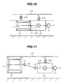
- Fig. 10 is a side view showing the construction of those other principal parts as seen from a lateral side of the hybrid vehicle with the vehicle drive device of this first embodiment mounted thereon.
- the same reference numerals as those in Figs. 1 to 3 represent the same portions as those in Figs. 1 to 3 .
- a driving force transducer 40' disposed below the springs is supported under a vehicle body 110 by dampers 70R and 70L.
- a basic construction of the driving force transducer 40' is the same as that shown in Fig. 4 . In this construction, constant velocity joints as shown in Fig. 4 are generally not used.
- the driving force transducer 40' and the electric motor 50 are supported by dampers 70C and 70D, respectively.
- Springs or shock absorbers are used as the dampers 70R, 70L, 70C and 70D.
- the driving force provided from the propeller shaft is distributed to right and left driving shafts 36R and 36L by the "below-the-spring" differential gear 40'.
- the second input shaft 41B of the driving force transducer 40' and the output shaft 51 of the electric motor 50 are level with each other. That is, the output shaft 51 of the electric motor 50 is present on an extension of the second input shaft 41B of the driving force transducer 40', so that the output shaft 51 of the electric motor 50 can be connected to the second input shaft 41B of the driving force transducer 40' by the spline bearing S1.
- the spline bearing S1 is easy to engage and disengage, can easily mount/dismount the electric motor 50 to/from the driving force transducer 40', and can transfer the driving force of the electric motor 50 to the driving force transducer 40'.
- the output shaft 51 of the electric motor 50 can be brought into engagement with the second input shaft 41B of the driving force transducer 40' through the spline bearing S1.
- the electric motor 50 is removed, only the electric motor 50 can be removed with ease because the driving force transducer 40' is held by the damper 70C.
- Fig. 11 is a side view showing a construction of the remaining principal parts as seen from a lateral side of the hybrid vehicle with the vehicle drive device of this first embodiment mounted thereon.
- the reference numerals as those in Fig. 10 represent the same portions as those in Fig. 10 .
- the driving force transducer 40' is supported under the 'vehicle body 110 by the damper 70C, but the electric motor 50 is mounted to the underside of the vehicle body 110. Consequently, the second input shaft 41B of the driving force transducer 40' and the output shaft 51 of the electric motor 50 are positioned at different heights. Therefore, the output shaft 51 of the electric motor 50 is connected to a shaft 38 through a constant velocity joint J5. The shaft 38 is connected to the second input shaft 41B of the driving force transducer 40' through a constant velocity joint J6.
- the constant velocity joint J5 is easy to engage and disengage, can mount/dismount the electric motor 50 easily to/from the driving force transducer 40', and can transmit the driving force of the electric motor 50 to the driving force transducer 40'.
- the output shaft 51 of the electric motor 50 can be brought into engagement with the second input shaft 41B of the driving force transducer 40' through the shaft 38 and the constant velocity joint J5.
- the electric motor 50 is removed, only the electric motor 50 can be removed with ease because the driving force transducer 40' is held by the damper 70C.
- the driving force transducer 40 and the electric motor 50 are constituted separately from each other and the output shaft 51 of the electric motor 50 is connected to the second input shaft 41B of the driving force transducer 40 through the spline bearing S1, it is possible to remove only the electric motor, thus improving maintainability.
- Fig. 12 is a plan view showing the construction of the hybrid vehicle which carries thereon the vehicle drive device of this second embodiment.
- the same reference numerals as those in Fig. 1 represent the same portions as those in Fig. 1 .
- the rotary shaft of the motor rotor 52R is perpendicular to the output shaft 27 of the driving force transducer 40.
- the rotary shaft of the motor rotor 52R in the electric motor 50 is disposed in parallel with an output shaft 42 of a driving force transducer 40A.
- the driving force transducer 40A includes a gear 43A connected to the output shaft 42L and a gear 43B connected to the gear 43A and having the second input shaft 41B.
- the inverter 65 and the battery 60 are not shown.
- the output shaft 51 of the electric motor 50 can be connected to the second input shaft 41B of the driving force transducer 40A by the spline bearing S1.
- the spline bearing S1 is easy to engage and disengage, can mount/dismount the electric motor 50 easily to/from the driving force transducer 40A, and can transfer the driving force from the electric motor 50 to the driving force transducer 40A.
- the output shaft 51 of the electric motor 50 can be mounted to the underside of the vehicle body 110A with the output shaft 51 engaged with the second input shaft 41B of the driving force transducer 40A through the spline bearing S1.
- the electric motor 50 is removed, only the electric motor 50 can be removed with ease because the driving force transducer 40A is mounted to the underside of the vehicle body 110A and is held thereby.
- the driving force transducer and the electric motor are constituted separately from each other and the output shaft of the electric motor is connected to the second input shaft of the driving force transducer through the spline bearing, it is possible to remove only the electric motor, thus improving maintainability.
- Fig. 13 is a plan view showing the construction of the hybrid vehicle which carries thereon the vehicle drive device of this third embodiment.
- the same reference numerals as those in Fig. 1 represent the same portions as those in Fig. 1 .
- Only one electric motor 50 is used in the example shown in Fig. 1 .
- a hybrid vehicle 100B according to this third embodiment is provided with two electric motors 50B1 and 50B2. Moreover, the rotary shaft of the motor rotor 52 is perpendicular to an output shaft 42 of a driving force transducer 40B.
- the driving force transducer 40B includes a bevel gear 44A1 connected to the output shaft 42R and a bevel gear 44B1 connected to the bevel gear 44A1 and having a second input shaft 41B1.
- the driving force transducer 40B further includes a bevel gear 44A2 connected to the output shaft 42L and a bevel gear 44B2 connected to the bevel gear 44A2 and having a third input shaft 41B1.
- the inverter 65 and the battery 60 are not shown.
- the second input shaft 41B1 of the driving force transducer 40B and an output shaft 51-1 of the electric motor 50B1 are level with each other, so that the output shaft 51-1 of the electric motor 50B1 can be connected to the second input shaft 41B1 of the driving force transducer 40B by a spline bearing S1-1.
- the output shaft 51-2 of the electric motor 50B2 can be connected to the third input shaft 41B2 of the driving force transducer 40B by a spline bearing S1-2.
- the spline bearings S1-1 and S1-2 are easy to engage and disengage, can mount/dismount the electric motors 50B1 and 50B2 easily to/from the driving force transducer 40B, and can transfer driving force from the electric motors 50B1 and 50B2 to the driving force transducer 40B.
- the electric motors 50B1 and 50B2 can be mounted to the underside of the vehicle body 110B with the output shafts 51-1 and 51-2 of the electric motors 50B1 and 50B2 engaged with the second input shaft 41B of the driving force transducer 40B by the spline shaft S1.
- the electric motors 50B1 and 50B2 are removed, only the electric motors 50B1 and 50B2 can be removed with ease because the driving force transducer 40B is mounted to the underside of the vehicle body 110B and is held thereby.
- the driving force transducer and the electric motors are constituted separately from each other and the output shafts of the electric motors are connected to the input shafts of the driving force transducer through the spline bearing, only the electric motors can be removed, thus improving maintainability.
- Fig. 14 is a plan view showing the construction of the hybrid vehicle which carries thereon the vehicle drive device of this fourth embodiment.
- the same reference numerals as those in Fig. 1 represent the same portions as those in Fig. 1 .
- a hybrid vehicle 100C is provided with two electric motors 50B1 and 50B2.
- a driving force transducer 40C includes a gear 43A1 connected to the output shaft 42R and a gear 43B1 connected to the gear 43A1 and having the second input shaft 41B1.
- the driving force transducer 40C further includes a gear 43A2 connected to the output shaft 42L and a gear 43B2 connected to the gear 43A2 and having the third input shaft 41B2.
- the inverter 65 and the battery 60 are not shown.
- the second input shaft 41B1 of the driving force transducer 40B and the output shaft 51-1 of the electric motor 50B1 are level with each other, so that the output shaft 51-1 of the electric motor 50B1 can be connected to the second input shaft 41B1 of the driving force transducer 40B by the spline bearing S1-1.
- the output shaft 51-2 of the electric motor 50B2 can be connected to the third input shaft 41B2 of the driving force transducer 40B by the spline bearing S1-2.
- the spline bearings S1-1 and S1-2 are easy to engage and disengage, can mount/dismount the electric motors 50B1 and 50B2 easily to/from the driving force transducer 40B, and can transfer the driving force from the electric motors 50B1 and 50B2 to the driving force transducer 40B.
- the electric motors 50B1 and 50B2 can be mounted to the underside of the vehicle body 110 with the output shafts 51-1 and 51-2 of the electric motors 50B1 and 50B2 engaged with the second input shaft 41B1 of the driving force transducer 40B by the spline bearings S1 (bearings S1-1 and S1-2).
- the electric motors 50B1 and 50B2 are removed, only the electric motors 50B1 and 50B2 can be removed with ease because the driving force transducer 40B is mounted to the underside of the vehicle body 110C and is held thereby.
- the driving force transducer and the electric motor are constituted separately from each other and the output shafts of the electric motors are connected to the input shafts of the driving force transducer through the spline bearings, only the electric motors can be removed, thus improving maintainability.
- Fig. 15 is a plan view showing the construction of the hybrid vehicle which carries thereon the vehicle drive device of this fifth embodiment.
- the same reference numerals as those in Fig. 1 represent the same portions as those in Fig. 1 .
- the vehicles shown in the examples of Fig. 1 and Figs. 12 to 14 are so-called FR2WD type vehicles wherein the internal combustion engine is disposed on the front side to drive rear wheels.
- the vehicle related to this fifth embodiment is a 4WD vehicle which carries a center differential 80 thereon to distribute the power of an internal combustion engine 10 to the front wheels FR and FL and the rear wheels RR and RL.
- An output shaft of the transmission 20 and a propeller shaft 30A are connected together by a constant velocity joint J7.
- the propeller shaft 30A and an input shat 81A of the center differential 80 are connected together by a constant velocity joint J8.
- the center differential 80 includes a planetary gear 82 and a gear 84.
- An input shaft 81A of the center differential 80 is connected to a planetary gear carrier of the planetary gear 82.
- a first output shaft 81B of the center differential 80 is connected to a sun gear of the planetary gear 82.
- a second output shaft 81C of the center differential 80 is connected to a ring gear of the planetary gear 82 through the gear 84.
- the first output shaft 81B of the center differential 80 and a propeller shaft 30B are connected together by a constant velocity joint J9.
- the propeller shaft 30B and the driving force transducer 40 are connected together by a constant velocity joint J10.
- the second output shaft 81C of the center differential 80 and a propeller shaft 30C are connected together by a constant velocity joint J11.
- the propeller shaft 30C and a front-side differential gear 90 are connected together by a constant velocity joint J12.
- Output shafts of the front-side differential gear 90 are connected to axles 34R' and 34L', respectively, through constant velocity joints J13R and J13L, connecting shafts 32R' and 32L', and constant velocity joints J14R and J14L.
- the driving force transducer 40 may be disposed, and an electric motor may be disposed on the opposite-to-propeller-shaft-side (i.e., on the vehicle front side).
- the driving force transducer and the electric motor are constituted separately from each other and the output shaft of the electric motor is connected to the input shaft of the driving force transducer through the spline bearing, only the electric motor can be removed, thus improving maintainability.
- the drive source is not limited to the internal combustion engine; another drive source (e.g., an electric motor) may also be used.
- the driving force transducer 40 is of an integral construction having all of differential, shift and clutch functions, it may be divided into several portions on a function-by-function basis (differential gear, clutch, shift/clutch). A construction may also be adopted which does not use a clutch and a transmission and does not use a shift function and an accompanying rotation preventing function.
- the propeller shaft and the electric motor are disposed so as not to interfere with each other, and even a smaller electric motor than in the prior art can afford equivalent performance. Besides, even when it is necessary to change the motor design, greater latitude with which the motor design is modified can be ensured because the interference with other products is diminished.
- the electric motor is disposed on the side opposite to the propeller shaft (on the vehicle rear side)
- the motor installed position is more rearward than in the case of disposing the motor on the front side of the differential gear. Therefore, the front-rear weight balance with respect to the internal combustion engine, which is heavy, is improved.
Applications Claiming Priority (1)
| Application Number | Priority Date | Filing Date | Title |
|---|---|---|---|
| JP2007003831A JP2008168783A (ja) | 2007-01-11 | 2007-01-11 | 車両駆動装置 |
Publications (2)
| Publication Number | Publication Date |
|---|---|
| EP1944185A2 true EP1944185A2 (de) | 2008-07-16 |
| EP1944185A3 EP1944185A3 (de) | 2010-03-10 |
Family
ID=39203140
Family Applications (1)
| Application Number | Title | Priority Date | Filing Date |
|---|---|---|---|
| EP08000501A Withdrawn EP1944185A3 (de) | 2007-01-11 | 2008-01-11 | Fahrzeugantriebsvorrichtung |
Country Status (4)
| Country | Link |
|---|---|
| US (1) | US20080176707A1 (de) |
| EP (1) | EP1944185A3 (de) |
| JP (1) | JP2008168783A (de) |
| CN (1) | CN101219638A (de) |
Families Citing this family (18)
| Publication number | Priority date | Publication date | Assignee | Title |
|---|---|---|---|---|
| JP5153587B2 (ja) * | 2008-11-14 | 2013-02-27 | 本田技研工業株式会社 | 動力装置 |
| JP5133935B2 (ja) * | 2009-05-07 | 2013-01-30 | Udトラックス株式会社 | パラレル式ハイブリッド車の動力伝達機構 |
| JP5297933B2 (ja) * | 2009-08-04 | 2013-09-25 | 由美子 杉浦 | 等速ジョイント |
| JP2011201387A (ja) * | 2010-03-25 | 2011-10-13 | Fuji Heavy Ind Ltd | ハイブリッド駆動装置 |
| US20110251007A1 (en) * | 2010-04-07 | 2011-10-13 | Tai-Her Yang | Dual gear train driving structure at input side of basin-type gear |
| JP2012224321A (ja) * | 2010-06-28 | 2012-11-15 | Nissan Motor Co Ltd | 変速制御装置及び変速制御方法 |
| DE102011102265A1 (de) | 2011-05-23 | 2012-04-12 | Daimler Ag | Anordnung eines Antriebsstrangs an einem Aufbau eines Kraftwagens |
| JP2013014302A (ja) * | 2011-07-02 | 2013-01-24 | Tadashi Takano | 電気走行可能な自動車 |
| US9126581B2 (en) * | 2013-05-08 | 2015-09-08 | GM Global Technology Operations LLC | Hybrid powertrain and modular rear drive unit for same |
| JP6176221B2 (ja) * | 2014-10-17 | 2017-08-09 | マツダ株式会社 | 車両の駆動装置 |
| JP2017036026A (ja) * | 2015-08-07 | 2017-02-16 | 株式会社デンソー | 車両の駆動装置 |
| DE102018201126A1 (de) * | 2017-02-01 | 2018-08-02 | Bosch Limited | Frontantriebseinheit für ein Hybridelektrofahrzeug |
| JP2018202925A (ja) * | 2017-05-31 | 2018-12-27 | 本田技研工業株式会社 | 動力伝達装置 |
| JP2019158073A (ja) * | 2018-03-15 | 2019-09-19 | ジヤトコ株式会社 | 自動変速機 |
| KR102091422B1 (ko) * | 2018-07-18 | 2020-03-23 | 한국생산기술연구원 | 링 타입 구동모터 및 이를 포함하는 파워트레인 |
| DE202019105419U1 (de) | 2018-10-01 | 2020-02-10 | Dana Automotive Systems Group, Llc | Mehrgang-Schaltgetriebe und damit hergestellte Antriebsachse |
| JP2020093665A (ja) | 2018-12-12 | 2020-06-18 | トヨタ自動車株式会社 | 車両用電気駆動装置 |
| US11598259B2 (en) * | 2019-08-29 | 2023-03-07 | Achates Power, Inc. | Hybrid drive system with an opposed-piston, internal combustion engine |
Citations (2)
| Publication number | Priority date | Publication date | Assignee | Title |
|---|---|---|---|---|
| JP2003291671A (ja) | 2002-03-29 | 2003-10-15 | Aisin Aw Co Ltd | ハイブリッド駆動装置を搭載したfrタイプの自動車 |
| JP2006103535A (ja) | 2004-10-06 | 2006-04-20 | Nissan Motor Co Ltd | ハイブリッド車両 |
Family Cites Families (5)
| Publication number | Priority date | Publication date | Assignee | Title |
|---|---|---|---|---|
| JPH03239631A (ja) * | 1990-02-15 | 1991-10-25 | Nissan Motor Co Ltd | 牽引車のハイブリッド構造 |
| JPH0715805A (ja) * | 1993-06-14 | 1995-01-17 | Tai-Her Yang | 転換蓄電式ディファレンシャル・カップリング複合動力システム |
| JP3350314B2 (ja) * | 1995-09-29 | 2002-11-25 | 富士重工業株式会社 | ハイブリッド自動車の駆動装置 |
| JP2005231526A (ja) * | 2004-02-20 | 2005-09-02 | Fuji Heavy Ind Ltd | ハイブリッド車両の駆動装置 |
| US7115058B2 (en) * | 2004-10-29 | 2006-10-03 | American Axle & Manufacturing, Inc. | Power-assisted differential assembly |
-
2007
- 2007-01-11 JP JP2007003831A patent/JP2008168783A/ja active Pending
-
2008
- 2008-01-10 CN CNA2008100030232A patent/CN101219638A/zh active Pending
- 2008-01-10 US US11/971,961 patent/US20080176707A1/en not_active Abandoned
- 2008-01-11 EP EP08000501A patent/EP1944185A3/de not_active Withdrawn
Patent Citations (2)
| Publication number | Priority date | Publication date | Assignee | Title |
|---|---|---|---|---|
| JP2003291671A (ja) | 2002-03-29 | 2003-10-15 | Aisin Aw Co Ltd | ハイブリッド駆動装置を搭載したfrタイプの自動車 |
| JP2006103535A (ja) | 2004-10-06 | 2006-04-20 | Nissan Motor Co Ltd | ハイブリッド車両 |
Also Published As
| Publication number | Publication date |
|---|---|
| CN101219638A (zh) | 2008-07-16 |
| EP1944185A3 (de) | 2010-03-10 |
| JP2008168783A (ja) | 2008-07-24 |
| US20080176707A1 (en) | 2008-07-24 |
Similar Documents
| Publication | Publication Date | Title |
|---|---|---|
| EP1944185A2 (de) | Fahrzeugantriebsvorrichtung | |
| JP7079582B2 (ja) | 補助動力装置付き車輪用軸受装置およびその補助動力装置 | |
| US9387756B1 (en) | Vehicle hybrid drive arrangement | |
| CA2810945C (en) | Powertrain system for hybrid vehicles having multiple modes of operation | |
| EP2522541B1 (de) | Fahrzeug mit vorder- und hinterradantrieb | |
| JP5883070B2 (ja) | トルクベクタリングデバイス | |
| JP7053951B2 (ja) | ハイブリッド車輌用パワーシステム | |
| JP3673863B2 (ja) | ハイブリッド自動車の駆動装置 | |
| US10710462B2 (en) | Driving device | |
| US7980349B2 (en) | Drive system for vehicle | |
| US20130252783A1 (en) | Powertrain system for hybrid vehicles having compound and split modes of operation | |
| JP5921773B2 (ja) | ハイブリッド駆動自動車用駆動装置 | |
| JP6976083B2 (ja) | 車両動力補助システムおよび車両従動輪回生システム | |
| JP7052262B2 (ja) | 四輪駆動車用駆動装置 | |
| WO2011105017A1 (ja) | 四輪駆動ハイブリッド車用動力伝達装置 | |
| JP2011218871A (ja) | スタンバイ四輪駆動車 | |
| CN109866589B (zh) | 一种基于对转双转子电机和轮毂电机的纯电驱动桥及其控制方法 | |
| JP3933125B2 (ja) | 車両の動力出力装置 | |
| WO2018056219A1 (ja) | 補助動力装置付き車輪用軸受装置 | |
| US20180111467A1 (en) | Hybrid transmission device | |
| JP6997584B2 (ja) | ハイブリッド車両のパワーユニット | |
| JP2006062571A (ja) | 電動車両の駆動装置 | |
| JP3775330B2 (ja) | ハイブリッド駆動装置を搭載したfrタイプの自動車 | |
| JP7284831B2 (ja) | ハイブリッドシステムの制御方法及び制御システム | |
| CN103068614A (zh) | 汽车传动系设备 |
Legal Events
| Date | Code | Title | Description |
|---|---|---|---|
| PUAI | Public reference made under article 153(3) epc to a published international application that has entered the european phase |
Free format text: ORIGINAL CODE: 0009012 |
|
| 17P | Request for examination filed |
Effective date: 20080122 |
|
| AK | Designated contracting states |
Kind code of ref document: A2 Designated state(s): AT BE BG CH CY CZ DE DK EE ES FI FR GB GR HR HU IE IS IT LI LT LU LV MC MT NL NO PL PT RO SE SI SK TR |
|
| AX | Request for extension of the european patent |
Extension state: AL BA MK RS |
|
| PUAL | Search report despatched |
Free format text: ORIGINAL CODE: 0009013 |
|
| AK | Designated contracting states |
Kind code of ref document: A3 Designated state(s): AT BE BG CH CY CZ DE DK EE ES FI FR GB GR HR HU IE IS IT LI LT LU LV MC MT NL NO PL PT RO SE SI SK TR |
|
| AX | Request for extension of the european patent |
Extension state: AL BA MK RS |
|
| RIC1 | Information provided on ipc code assigned before grant |
Ipc: B60K 5/02 20060101ALN20100204BHEP Ipc: B60K 6/387 20071001ALI20100204BHEP Ipc: B60K 6/48 20071001ALI20100204BHEP Ipc: B60K 6/40 20071001AFI20080403BHEP |
|
| STAA | Information on the status of an ep patent application or granted ep patent |
Free format text: STATUS: THE APPLICATION HAS BEEN WITHDRAWN |
|
| 18W | Application withdrawn |
Effective date: 20100308 |