JP2017036026A - 車両の駆動装置 - Google Patents
車両の駆動装置 Download PDFInfo
- Publication number
- JP2017036026A JP2017036026A JP2016021262A JP2016021262A JP2017036026A JP 2017036026 A JP2017036026 A JP 2017036026A JP 2016021262 A JP2016021262 A JP 2016021262A JP 2016021262 A JP2016021262 A JP 2016021262A JP 2017036026 A JP2017036026 A JP 2017036026A
- Authority
- JP
- Japan
- Prior art keywords
- vehicle
- speed reducer
- engine
- case
- drive device
- Prior art date
- Legal status (The legal status is an assumption and is not a legal conclusion. Google has not performed a legal analysis and makes no representation as to the accuracy of the status listed.)
- Pending
Links
Images


Classifications
-
- B—PERFORMING OPERATIONS; TRANSPORTING
- B60—VEHICLES IN GENERAL
- B60K—ARRANGEMENT OR MOUNTING OF PROPULSION UNITS OR OF TRANSMISSIONS IN VEHICLES; ARRANGEMENT OR MOUNTING OF PLURAL DIVERSE PRIME-MOVERS IN VEHICLES; AUXILIARY DRIVES FOR VEHICLES; INSTRUMENTATION OR DASHBOARDS FOR VEHICLES; ARRANGEMENTS IN CONNECTION WITH COOLING, AIR INTAKE, GAS EXHAUST OR FUEL SUPPLY OF PROPULSION UNITS IN VEHICLES
- B60K1/00—Arrangement or mounting of electrical propulsion units
- B60K1/04—Arrangement or mounting of electrical propulsion units of the electric storage means for propulsion
-
- B—PERFORMING OPERATIONS; TRANSPORTING
- B60—VEHICLES IN GENERAL
- B60K—ARRANGEMENT OR MOUNTING OF PROPULSION UNITS OR OF TRANSMISSIONS IN VEHICLES; ARRANGEMENT OR MOUNTING OF PLURAL DIVERSE PRIME-MOVERS IN VEHICLES; AUXILIARY DRIVES FOR VEHICLES; INSTRUMENTATION OR DASHBOARDS FOR VEHICLES; ARRANGEMENTS IN CONNECTION WITH COOLING, AIR INTAKE, GAS EXHAUST OR FUEL SUPPLY OF PROPULSION UNITS IN VEHICLES
- B60K11/00—Arrangement in connection with cooling of propulsion units
- B60K11/02—Arrangement in connection with cooling of propulsion units with liquid cooling
-
- B—PERFORMING OPERATIONS; TRANSPORTING
- B60—VEHICLES IN GENERAL
- B60K—ARRANGEMENT OR MOUNTING OF PROPULSION UNITS OR OF TRANSMISSIONS IN VEHICLES; ARRANGEMENT OR MOUNTING OF PLURAL DIVERSE PRIME-MOVERS IN VEHICLES; AUXILIARY DRIVES FOR VEHICLES; INSTRUMENTATION OR DASHBOARDS FOR VEHICLES; ARRANGEMENTS IN CONNECTION WITH COOLING, AIR INTAKE, GAS EXHAUST OR FUEL SUPPLY OF PROPULSION UNITS IN VEHICLES
- B60K17/00—Arrangement or mounting of transmissions in vehicles
- B60K17/04—Arrangement or mounting of transmissions in vehicles characterised by arrangement, location, or kind of gearing
- B60K17/16—Arrangement or mounting of transmissions in vehicles characterised by arrangement, location, or kind of gearing of differential gearing
-
- B—PERFORMING OPERATIONS; TRANSPORTING
- B60—VEHICLES IN GENERAL
- B60K—ARRANGEMENT OR MOUNTING OF PROPULSION UNITS OR OF TRANSMISSIONS IN VEHICLES; ARRANGEMENT OR MOUNTING OF PLURAL DIVERSE PRIME-MOVERS IN VEHICLES; AUXILIARY DRIVES FOR VEHICLES; INSTRUMENTATION OR DASHBOARDS FOR VEHICLES; ARRANGEMENTS IN CONNECTION WITH COOLING, AIR INTAKE, GAS EXHAUST OR FUEL SUPPLY OF PROPULSION UNITS IN VEHICLES
- B60K6/00—Arrangement or mounting of plural diverse prime-movers for mutual or common propulsion, e.g. hybrid propulsion systems comprising electric motors and internal combustion engines ; Control systems therefor, i.e. systems controlling two or more prime movers, or controlling one of these prime movers and any of the transmission, drive or drive units Informative references: mechanical gearings with secondary electric drive F16H3/72; arrangements for handling mechanical energy structurally associated with the dynamo-electric machine H02K7/00; machines comprising structurally interrelated motor and generator parts H02K51/00; dynamo-electric machines not otherwise provided for in H02K see H02K99/00
- B60K6/20—Arrangement or mounting of plural diverse prime-movers for mutual or common propulsion, e.g. hybrid propulsion systems comprising electric motors and internal combustion engines ; Control systems therefor, i.e. systems controlling two or more prime movers, or controlling one of these prime movers and any of the transmission, drive or drive units Informative references: mechanical gearings with secondary electric drive F16H3/72; arrangements for handling mechanical energy structurally associated with the dynamo-electric machine H02K7/00; machines comprising structurally interrelated motor and generator parts H02K51/00; dynamo-electric machines not otherwise provided for in H02K see H02K99/00 the prime-movers consisting of electric motors and internal combustion engines, e.g. HEVs
- B60K6/22—Arrangement or mounting of plural diverse prime-movers for mutual or common propulsion, e.g. hybrid propulsion systems comprising electric motors and internal combustion engines ; Control systems therefor, i.e. systems controlling two or more prime movers, or controlling one of these prime movers and any of the transmission, drive or drive units Informative references: mechanical gearings with secondary electric drive F16H3/72; arrangements for handling mechanical energy structurally associated with the dynamo-electric machine H02K7/00; machines comprising structurally interrelated motor and generator parts H02K51/00; dynamo-electric machines not otherwise provided for in H02K see H02K99/00 the prime-movers consisting of electric motors and internal combustion engines, e.g. HEVs characterised by apparatus, components or means specially adapted for HEVs
- B60K6/24—Arrangement or mounting of plural diverse prime-movers for mutual or common propulsion, e.g. hybrid propulsion systems comprising electric motors and internal combustion engines ; Control systems therefor, i.e. systems controlling two or more prime movers, or controlling one of these prime movers and any of the transmission, drive or drive units Informative references: mechanical gearings with secondary electric drive F16H3/72; arrangements for handling mechanical energy structurally associated with the dynamo-electric machine H02K7/00; machines comprising structurally interrelated motor and generator parts H02K51/00; dynamo-electric machines not otherwise provided for in H02K see H02K99/00 the prime-movers consisting of electric motors and internal combustion engines, e.g. HEVs characterised by apparatus, components or means specially adapted for HEVs characterised by the combustion engines
-
- B—PERFORMING OPERATIONS; TRANSPORTING
- B60—VEHICLES IN GENERAL
- B60K—ARRANGEMENT OR MOUNTING OF PROPULSION UNITS OR OF TRANSMISSIONS IN VEHICLES; ARRANGEMENT OR MOUNTING OF PLURAL DIVERSE PRIME-MOVERS IN VEHICLES; AUXILIARY DRIVES FOR VEHICLES; INSTRUMENTATION OR DASHBOARDS FOR VEHICLES; ARRANGEMENTS IN CONNECTION WITH COOLING, AIR INTAKE, GAS EXHAUST OR FUEL SUPPLY OF PROPULSION UNITS IN VEHICLES
- B60K6/00—Arrangement or mounting of plural diverse prime-movers for mutual or common propulsion, e.g. hybrid propulsion systems comprising electric motors and internal combustion engines ; Control systems therefor, i.e. systems controlling two or more prime movers, or controlling one of these prime movers and any of the transmission, drive or drive units Informative references: mechanical gearings with secondary electric drive F16H3/72; arrangements for handling mechanical energy structurally associated with the dynamo-electric machine H02K7/00; machines comprising structurally interrelated motor and generator parts H02K51/00; dynamo-electric machines not otherwise provided for in H02K see H02K99/00
- B60K6/20—Arrangement or mounting of plural diverse prime-movers for mutual or common propulsion, e.g. hybrid propulsion systems comprising electric motors and internal combustion engines ; Control systems therefor, i.e. systems controlling two or more prime movers, or controlling one of these prime movers and any of the transmission, drive or drive units Informative references: mechanical gearings with secondary electric drive F16H3/72; arrangements for handling mechanical energy structurally associated with the dynamo-electric machine H02K7/00; machines comprising structurally interrelated motor and generator parts H02K51/00; dynamo-electric machines not otherwise provided for in H02K see H02K99/00 the prime-movers consisting of electric motors and internal combustion engines, e.g. HEVs
- B60K6/22—Arrangement or mounting of plural diverse prime-movers for mutual or common propulsion, e.g. hybrid propulsion systems comprising electric motors and internal combustion engines ; Control systems therefor, i.e. systems controlling two or more prime movers, or controlling one of these prime movers and any of the transmission, drive or drive units Informative references: mechanical gearings with secondary electric drive F16H3/72; arrangements for handling mechanical energy structurally associated with the dynamo-electric machine H02K7/00; machines comprising structurally interrelated motor and generator parts H02K51/00; dynamo-electric machines not otherwise provided for in H02K see H02K99/00 the prime-movers consisting of electric motors and internal combustion engines, e.g. HEVs characterised by apparatus, components or means specially adapted for HEVs
- B60K6/26—Arrangement or mounting of plural diverse prime-movers for mutual or common propulsion, e.g. hybrid propulsion systems comprising electric motors and internal combustion engines ; Control systems therefor, i.e. systems controlling two or more prime movers, or controlling one of these prime movers and any of the transmission, drive or drive units Informative references: mechanical gearings with secondary electric drive F16H3/72; arrangements for handling mechanical energy structurally associated with the dynamo-electric machine H02K7/00; machines comprising structurally interrelated motor and generator parts H02K51/00; dynamo-electric machines not otherwise provided for in H02K see H02K99/00 the prime-movers consisting of electric motors and internal combustion engines, e.g. HEVs characterised by apparatus, components or means specially adapted for HEVs characterised by the motors or the generators
-
- B—PERFORMING OPERATIONS; TRANSPORTING
- B60—VEHICLES IN GENERAL
- B60K—ARRANGEMENT OR MOUNTING OF PROPULSION UNITS OR OF TRANSMISSIONS IN VEHICLES; ARRANGEMENT OR MOUNTING OF PLURAL DIVERSE PRIME-MOVERS IN VEHICLES; AUXILIARY DRIVES FOR VEHICLES; INSTRUMENTATION OR DASHBOARDS FOR VEHICLES; ARRANGEMENTS IN CONNECTION WITH COOLING, AIR INTAKE, GAS EXHAUST OR FUEL SUPPLY OF PROPULSION UNITS IN VEHICLES
- B60K6/00—Arrangement or mounting of plural diverse prime-movers for mutual or common propulsion, e.g. hybrid propulsion systems comprising electric motors and internal combustion engines ; Control systems therefor, i.e. systems controlling two or more prime movers, or controlling one of these prime movers and any of the transmission, drive or drive units Informative references: mechanical gearings with secondary electric drive F16H3/72; arrangements for handling mechanical energy structurally associated with the dynamo-electric machine H02K7/00; machines comprising structurally interrelated motor and generator parts H02K51/00; dynamo-electric machines not otherwise provided for in H02K see H02K99/00
- B60K6/20—Arrangement or mounting of plural diverse prime-movers for mutual or common propulsion, e.g. hybrid propulsion systems comprising electric motors and internal combustion engines ; Control systems therefor, i.e. systems controlling two or more prime movers, or controlling one of these prime movers and any of the transmission, drive or drive units Informative references: mechanical gearings with secondary electric drive F16H3/72; arrangements for handling mechanical energy structurally associated with the dynamo-electric machine H02K7/00; machines comprising structurally interrelated motor and generator parts H02K51/00; dynamo-electric machines not otherwise provided for in H02K see H02K99/00 the prime-movers consisting of electric motors and internal combustion engines, e.g. HEVs
- B60K6/22—Arrangement or mounting of plural diverse prime-movers for mutual or common propulsion, e.g. hybrid propulsion systems comprising electric motors and internal combustion engines ; Control systems therefor, i.e. systems controlling two or more prime movers, or controlling one of these prime movers and any of the transmission, drive or drive units Informative references: mechanical gearings with secondary electric drive F16H3/72; arrangements for handling mechanical energy structurally associated with the dynamo-electric machine H02K7/00; machines comprising structurally interrelated motor and generator parts H02K51/00; dynamo-electric machines not otherwise provided for in H02K see H02K99/00 the prime-movers consisting of electric motors and internal combustion engines, e.g. HEVs characterised by apparatus, components or means specially adapted for HEVs
- B60K6/36—Arrangement or mounting of plural diverse prime-movers for mutual or common propulsion, e.g. hybrid propulsion systems comprising electric motors and internal combustion engines ; Control systems therefor, i.e. systems controlling two or more prime movers, or controlling one of these prime movers and any of the transmission, drive or drive units Informative references: mechanical gearings with secondary electric drive F16H3/72; arrangements for handling mechanical energy structurally associated with the dynamo-electric machine H02K7/00; machines comprising structurally interrelated motor and generator parts H02K51/00; dynamo-electric machines not otherwise provided for in H02K see H02K99/00 the prime-movers consisting of electric motors and internal combustion engines, e.g. HEVs characterised by apparatus, components or means specially adapted for HEVs characterised by the transmission gearings
-
- B—PERFORMING OPERATIONS; TRANSPORTING
- B60—VEHICLES IN GENERAL
- B60K—ARRANGEMENT OR MOUNTING OF PROPULSION UNITS OR OF TRANSMISSIONS IN VEHICLES; ARRANGEMENT OR MOUNTING OF PLURAL DIVERSE PRIME-MOVERS IN VEHICLES; AUXILIARY DRIVES FOR VEHICLES; INSTRUMENTATION OR DASHBOARDS FOR VEHICLES; ARRANGEMENTS IN CONNECTION WITH COOLING, AIR INTAKE, GAS EXHAUST OR FUEL SUPPLY OF PROPULSION UNITS IN VEHICLES
- B60K6/00—Arrangement or mounting of plural diverse prime-movers for mutual or common propulsion, e.g. hybrid propulsion systems comprising electric motors and internal combustion engines ; Control systems therefor, i.e. systems controlling two or more prime movers, or controlling one of these prime movers and any of the transmission, drive or drive units Informative references: mechanical gearings with secondary electric drive F16H3/72; arrangements for handling mechanical energy structurally associated with the dynamo-electric machine H02K7/00; machines comprising structurally interrelated motor and generator parts H02K51/00; dynamo-electric machines not otherwise provided for in H02K see H02K99/00
- B60K6/20—Arrangement or mounting of plural diverse prime-movers for mutual or common propulsion, e.g. hybrid propulsion systems comprising electric motors and internal combustion engines ; Control systems therefor, i.e. systems controlling two or more prime movers, or controlling one of these prime movers and any of the transmission, drive or drive units Informative references: mechanical gearings with secondary electric drive F16H3/72; arrangements for handling mechanical energy structurally associated with the dynamo-electric machine H02K7/00; machines comprising structurally interrelated motor and generator parts H02K51/00; dynamo-electric machines not otherwise provided for in H02K see H02K99/00 the prime-movers consisting of electric motors and internal combustion engines, e.g. HEVs
- B60K6/22—Arrangement or mounting of plural diverse prime-movers for mutual or common propulsion, e.g. hybrid propulsion systems comprising electric motors and internal combustion engines ; Control systems therefor, i.e. systems controlling two or more prime movers, or controlling one of these prime movers and any of the transmission, drive or drive units Informative references: mechanical gearings with secondary electric drive F16H3/72; arrangements for handling mechanical energy structurally associated with the dynamo-electric machine H02K7/00; machines comprising structurally interrelated motor and generator parts H02K51/00; dynamo-electric machines not otherwise provided for in H02K see H02K99/00 the prime-movers consisting of electric motors and internal combustion engines, e.g. HEVs characterised by apparatus, components or means specially adapted for HEVs
- B60K6/40—Arrangement or mounting of plural diverse prime-movers for mutual or common propulsion, e.g. hybrid propulsion systems comprising electric motors and internal combustion engines ; Control systems therefor, i.e. systems controlling two or more prime movers, or controlling one of these prime movers and any of the transmission, drive or drive units Informative references: mechanical gearings with secondary electric drive F16H3/72; arrangements for handling mechanical energy structurally associated with the dynamo-electric machine H02K7/00; machines comprising structurally interrelated motor and generator parts H02K51/00; dynamo-electric machines not otherwise provided for in H02K see H02K99/00 the prime-movers consisting of electric motors and internal combustion engines, e.g. HEVs characterised by apparatus, components or means specially adapted for HEVs characterised by the assembly or relative disposition of components
-
- B—PERFORMING OPERATIONS; TRANSPORTING
- B60—VEHICLES IN GENERAL
- B60K—ARRANGEMENT OR MOUNTING OF PROPULSION UNITS OR OF TRANSMISSIONS IN VEHICLES; ARRANGEMENT OR MOUNTING OF PLURAL DIVERSE PRIME-MOVERS IN VEHICLES; AUXILIARY DRIVES FOR VEHICLES; INSTRUMENTATION OR DASHBOARDS FOR VEHICLES; ARRANGEMENTS IN CONNECTION WITH COOLING, AIR INTAKE, GAS EXHAUST OR FUEL SUPPLY OF PROPULSION UNITS IN VEHICLES
- B60K6/00—Arrangement or mounting of plural diverse prime-movers for mutual or common propulsion, e.g. hybrid propulsion systems comprising electric motors and internal combustion engines ; Control systems therefor, i.e. systems controlling two or more prime movers, or controlling one of these prime movers and any of the transmission, drive or drive units Informative references: mechanical gearings with secondary electric drive F16H3/72; arrangements for handling mechanical energy structurally associated with the dynamo-electric machine H02K7/00; machines comprising structurally interrelated motor and generator parts H02K51/00; dynamo-electric machines not otherwise provided for in H02K see H02K99/00
- B60K6/20—Arrangement or mounting of plural diverse prime-movers for mutual or common propulsion, e.g. hybrid propulsion systems comprising electric motors and internal combustion engines ; Control systems therefor, i.e. systems controlling two or more prime movers, or controlling one of these prime movers and any of the transmission, drive or drive units Informative references: mechanical gearings with secondary electric drive F16H3/72; arrangements for handling mechanical energy structurally associated with the dynamo-electric machine H02K7/00; machines comprising structurally interrelated motor and generator parts H02K51/00; dynamo-electric machines not otherwise provided for in H02K see H02K99/00 the prime-movers consisting of electric motors and internal combustion engines, e.g. HEVs
- B60K6/42—Arrangement or mounting of plural diverse prime-movers for mutual or common propulsion, e.g. hybrid propulsion systems comprising electric motors and internal combustion engines ; Control systems therefor, i.e. systems controlling two or more prime movers, or controlling one of these prime movers and any of the transmission, drive or drive units Informative references: mechanical gearings with secondary electric drive F16H3/72; arrangements for handling mechanical energy structurally associated with the dynamo-electric machine H02K7/00; machines comprising structurally interrelated motor and generator parts H02K51/00; dynamo-electric machines not otherwise provided for in H02K see H02K99/00 the prime-movers consisting of electric motors and internal combustion engines, e.g. HEVs characterised by the architecture of the hybrid electric vehicle
- B60K6/48—Parallel type
-
- B—PERFORMING OPERATIONS; TRANSPORTING
- B60—VEHICLES IN GENERAL
- B60K—ARRANGEMENT OR MOUNTING OF PROPULSION UNITS OR OF TRANSMISSIONS IN VEHICLES; ARRANGEMENT OR MOUNTING OF PLURAL DIVERSE PRIME-MOVERS IN VEHICLES; AUXILIARY DRIVES FOR VEHICLES; INSTRUMENTATION OR DASHBOARDS FOR VEHICLES; ARRANGEMENTS IN CONNECTION WITH COOLING, AIR INTAKE, GAS EXHAUST OR FUEL SUPPLY OF PROPULSION UNITS IN VEHICLES
- B60K6/00—Arrangement or mounting of plural diverse prime-movers for mutual or common propulsion, e.g. hybrid propulsion systems comprising electric motors and internal combustion engines ; Control systems therefor, i.e. systems controlling two or more prime movers, or controlling one of these prime movers and any of the transmission, drive or drive units Informative references: mechanical gearings with secondary electric drive F16H3/72; arrangements for handling mechanical energy structurally associated with the dynamo-electric machine H02K7/00; machines comprising structurally interrelated motor and generator parts H02K51/00; dynamo-electric machines not otherwise provided for in H02K see H02K99/00
- B60K6/20—Arrangement or mounting of plural diverse prime-movers for mutual or common propulsion, e.g. hybrid propulsion systems comprising electric motors and internal combustion engines ; Control systems therefor, i.e. systems controlling two or more prime movers, or controlling one of these prime movers and any of the transmission, drive or drive units Informative references: mechanical gearings with secondary electric drive F16H3/72; arrangements for handling mechanical energy structurally associated with the dynamo-electric machine H02K7/00; machines comprising structurally interrelated motor and generator parts H02K51/00; dynamo-electric machines not otherwise provided for in H02K see H02K99/00 the prime-movers consisting of electric motors and internal combustion engines, e.g. HEVs
- B60K6/50—Architecture of the driveline characterised by arrangement or kind of transmission units
- B60K6/54—Transmission for changing ratio
- B60K6/547—Transmission for changing ratio the transmission being a stepped gearing
-
- B—PERFORMING OPERATIONS; TRANSPORTING
- B60—VEHICLES IN GENERAL
- B60L—PROPULSION OF ELECTRICALLY-PROPELLED VEHICLES; SUPPLYING ELECTRIC POWER FOR AUXILIARY EQUIPMENT OF ELECTRICALLY-PROPELLED VEHICLES; ELECTRODYNAMIC BRAKE SYSTEMS FOR VEHICLES IN GENERAL; MAGNETIC SUSPENSION OR LEVITATION FOR VEHICLES; MONITORING OPERATING VARIABLES OF ELECTRICALLY-PROPELLED VEHICLES; ELECTRIC SAFETY DEVICES FOR ELECTRICALLY-PROPELLED VEHICLES
- B60L50/00—Electric propulsion with power supplied within the vehicle
- B60L50/10—Electric propulsion with power supplied within the vehicle using propulsion power supplied by engine-driven generators, e.g. generators driven by combustion engines
- B60L50/16—Electric propulsion with power supplied within the vehicle using propulsion power supplied by engine-driven generators, e.g. generators driven by combustion engines with provision for separate direct mechanical propulsion
-
- H—ELECTRICITY
- H02—GENERATION; CONVERSION OR DISTRIBUTION OF ELECTRIC POWER
- H02K—DYNAMO-ELECTRIC MACHINES
- H02K3/00—Details of windings
- H02K3/04—Windings characterised by the conductor shape, form or construction, e.g. with bar conductors
- H02K3/24—Windings characterised by the conductor shape, form or construction, e.g. with bar conductors with channels or ducts for cooling medium between the conductors
-
- H—ELECTRICITY
- H02—GENERATION; CONVERSION OR DISTRIBUTION OF ELECTRIC POWER
- H02K—DYNAMO-ELECTRIC MACHINES
- H02K3/00—Details of windings
- H02K3/32—Windings characterised by the shape, form or construction of the insulation
- H02K3/34—Windings characterised by the shape, form or construction of the insulation between conductors or between conductor and core, e.g. slot insulation
- H02K3/345—Windings characterised by the shape, form or construction of the insulation between conductors or between conductor and core, e.g. slot insulation between conductor and core, e.g. slot insulation
-
- H—ELECTRICITY
- H02—GENERATION; CONVERSION OR DISTRIBUTION OF ELECTRIC POWER
- H02K—DYNAMO-ELECTRIC MACHINES
- H02K7/00—Arrangements for handling mechanical energy structurally associated with dynamo-electric machines, e.g. structural association with mechanical driving motors or auxiliary dynamo-electric machines
- H02K7/006—Structural association of a motor or generator with the drive train of a motor vehicle
-
- H—ELECTRICITY
- H02—GENERATION; CONVERSION OR DISTRIBUTION OF ELECTRIC POWER
- H02K—DYNAMO-ELECTRIC MACHINES
- H02K7/00—Arrangements for handling mechanical energy structurally associated with dynamo-electric machines, e.g. structural association with mechanical driving motors or auxiliary dynamo-electric machines
- H02K7/10—Structural association with clutches, brakes, gears, pulleys or mechanical starters
- H02K7/116—Structural association with clutches, brakes, gears, pulleys or mechanical starters with gears
-
- H—ELECTRICITY
- H02—GENERATION; CONVERSION OR DISTRIBUTION OF ELECTRIC POWER
- H02K—DYNAMO-ELECTRIC MACHINES
- H02K9/00—Arrangements for cooling or ventilating
- H02K9/19—Arrangements for cooling or ventilating for machines with closed casing and closed-circuit cooling using a liquid cooling medium, e.g. oil
- H02K9/197—Arrangements for cooling or ventilating for machines with closed casing and closed-circuit cooling using a liquid cooling medium, e.g. oil in which the rotor or stator space is fluid-tight, e.g. to provide for different cooling media for rotor and stator
-
- B—PERFORMING OPERATIONS; TRANSPORTING
- B60—VEHICLES IN GENERAL
- B60K—ARRANGEMENT OR MOUNTING OF PROPULSION UNITS OR OF TRANSMISSIONS IN VEHICLES; ARRANGEMENT OR MOUNTING OF PLURAL DIVERSE PRIME-MOVERS IN VEHICLES; AUXILIARY DRIVES FOR VEHICLES; INSTRUMENTATION OR DASHBOARDS FOR VEHICLES; ARRANGEMENTS IN CONNECTION WITH COOLING, AIR INTAKE, GAS EXHAUST OR FUEL SUPPLY OF PROPULSION UNITS IN VEHICLES
- B60K6/00—Arrangement or mounting of plural diverse prime-movers for mutual or common propulsion, e.g. hybrid propulsion systems comprising electric motors and internal combustion engines ; Control systems therefor, i.e. systems controlling two or more prime movers, or controlling one of these prime movers and any of the transmission, drive or drive units Informative references: mechanical gearings with secondary electric drive F16H3/72; arrangements for handling mechanical energy structurally associated with the dynamo-electric machine H02K7/00; machines comprising structurally interrelated motor and generator parts H02K51/00; dynamo-electric machines not otherwise provided for in H02K see H02K99/00
- B60K6/20—Arrangement or mounting of plural diverse prime-movers for mutual or common propulsion, e.g. hybrid propulsion systems comprising electric motors and internal combustion engines ; Control systems therefor, i.e. systems controlling two or more prime movers, or controlling one of these prime movers and any of the transmission, drive or drive units Informative references: mechanical gearings with secondary electric drive F16H3/72; arrangements for handling mechanical energy structurally associated with the dynamo-electric machine H02K7/00; machines comprising structurally interrelated motor and generator parts H02K51/00; dynamo-electric machines not otherwise provided for in H02K see H02K99/00 the prime-movers consisting of electric motors and internal combustion engines, e.g. HEVs
- B60K6/42—Arrangement or mounting of plural diverse prime-movers for mutual or common propulsion, e.g. hybrid propulsion systems comprising electric motors and internal combustion engines ; Control systems therefor, i.e. systems controlling two or more prime movers, or controlling one of these prime movers and any of the transmission, drive or drive units Informative references: mechanical gearings with secondary electric drive F16H3/72; arrangements for handling mechanical energy structurally associated with the dynamo-electric machine H02K7/00; machines comprising structurally interrelated motor and generator parts H02K51/00; dynamo-electric machines not otherwise provided for in H02K see H02K99/00 the prime-movers consisting of electric motors and internal combustion engines, e.g. HEVs characterised by the architecture of the hybrid electric vehicle
- B60K6/48—Parallel type
- B60K2006/4808—Electric machine connected or connectable to gearbox output shaft
-
- B—PERFORMING OPERATIONS; TRANSPORTING
- B60—VEHICLES IN GENERAL
- B60K—ARRANGEMENT OR MOUNTING OF PROPULSION UNITS OR OF TRANSMISSIONS IN VEHICLES; ARRANGEMENT OR MOUNTING OF PLURAL DIVERSE PRIME-MOVERS IN VEHICLES; AUXILIARY DRIVES FOR VEHICLES; INSTRUMENTATION OR DASHBOARDS FOR VEHICLES; ARRANGEMENTS IN CONNECTION WITH COOLING, AIR INTAKE, GAS EXHAUST OR FUEL SUPPLY OF PROPULSION UNITS IN VEHICLES
- B60K6/00—Arrangement or mounting of plural diverse prime-movers for mutual or common propulsion, e.g. hybrid propulsion systems comprising electric motors and internal combustion engines ; Control systems therefor, i.e. systems controlling two or more prime movers, or controlling one of these prime movers and any of the transmission, drive or drive units Informative references: mechanical gearings with secondary electric drive F16H3/72; arrangements for handling mechanical energy structurally associated with the dynamo-electric machine H02K7/00; machines comprising structurally interrelated motor and generator parts H02K51/00; dynamo-electric machines not otherwise provided for in H02K see H02K99/00
- B60K6/20—Arrangement or mounting of plural diverse prime-movers for mutual or common propulsion, e.g. hybrid propulsion systems comprising electric motors and internal combustion engines ; Control systems therefor, i.e. systems controlling two or more prime movers, or controlling one of these prime movers and any of the transmission, drive or drive units Informative references: mechanical gearings with secondary electric drive F16H3/72; arrangements for handling mechanical energy structurally associated with the dynamo-electric machine H02K7/00; machines comprising structurally interrelated motor and generator parts H02K51/00; dynamo-electric machines not otherwise provided for in H02K see H02K99/00 the prime-movers consisting of electric motors and internal combustion engines, e.g. HEVs
- B60K6/42—Arrangement or mounting of plural diverse prime-movers for mutual or common propulsion, e.g. hybrid propulsion systems comprising electric motors and internal combustion engines ; Control systems therefor, i.e. systems controlling two or more prime movers, or controlling one of these prime movers and any of the transmission, drive or drive units Informative references: mechanical gearings with secondary electric drive F16H3/72; arrangements for handling mechanical energy structurally associated with the dynamo-electric machine H02K7/00; machines comprising structurally interrelated motor and generator parts H02K51/00; dynamo-electric machines not otherwise provided for in H02K see H02K99/00 the prime-movers consisting of electric motors and internal combustion engines, e.g. HEVs characterised by the architecture of the hybrid electric vehicle
- B60K6/48—Parallel type
- B60K2006/4833—Step up or reduction gearing driving generator, e.g. to operate generator in most efficient speed range
-
- B—PERFORMING OPERATIONS; TRANSPORTING
- B60—VEHICLES IN GENERAL
- B60L—PROPULSION OF ELECTRICALLY-PROPELLED VEHICLES; SUPPLYING ELECTRIC POWER FOR AUXILIARY EQUIPMENT OF ELECTRICALLY-PROPELLED VEHICLES; ELECTRODYNAMIC BRAKE SYSTEMS FOR VEHICLES IN GENERAL; MAGNETIC SUSPENSION OR LEVITATION FOR VEHICLES; MONITORING OPERATING VARIABLES OF ELECTRICALLY-PROPELLED VEHICLES; ELECTRIC SAFETY DEVICES FOR ELECTRICALLY-PROPELLED VEHICLES
- B60L2240/00—Control parameters of input or output; Target parameters
- B60L2240/40—Drive Train control parameters
- B60L2240/48—Drive Train control parameters related to transmissions
-
- B—PERFORMING OPERATIONS; TRANSPORTING
- B62—LAND VEHICLES FOR TRAVELLING OTHERWISE THAN ON RAILS
- B62D—MOTOR VEHICLES; TRAILERS
- B62D25/00—Superstructure or monocoque structure sub-units; Parts or details thereof not otherwise provided for
- B62D25/20—Floors or bottom sub-units
-
- B—PERFORMING OPERATIONS; TRANSPORTING
- B62—LAND VEHICLES FOR TRAVELLING OTHERWISE THAN ON RAILS
- B62D—MOTOR VEHICLES; TRAILERS
- B62D25/00—Superstructure or monocoque structure sub-units; Parts or details thereof not otherwise provided for
- B62D25/20—Floors or bottom sub-units
- B62D25/2009—Floors or bottom sub-units in connection with other superstructure subunits
-
- H—ELECTRICITY
- H02—GENERATION; CONVERSION OR DISTRIBUTION OF ELECTRIC POWER
- H02K—DYNAMO-ELECTRIC MACHINES
- H02K3/00—Details of windings
- H02K3/04—Windings characterised by the conductor shape, form or construction, e.g. with bar conductors
- H02K3/12—Windings characterised by the conductor shape, form or construction, e.g. with bar conductors arranged in slots
-
- Y—GENERAL TAGGING OF NEW TECHNOLOGICAL DEVELOPMENTS; GENERAL TAGGING OF CROSS-SECTIONAL TECHNOLOGIES SPANNING OVER SEVERAL SECTIONS OF THE IPC; TECHNICAL SUBJECTS COVERED BY FORMER USPC CROSS-REFERENCE ART COLLECTIONS [XRACs] AND DIGESTS
- Y02—TECHNOLOGIES OR APPLICATIONS FOR MITIGATION OR ADAPTATION AGAINST CLIMATE CHANGE
- Y02T—CLIMATE CHANGE MITIGATION TECHNOLOGIES RELATED TO TRANSPORTATION
- Y02T10/00—Road transport of goods or passengers
- Y02T10/60—Other road transportation technologies with climate change mitigation effect
- Y02T10/62—Hybrid vehicles
-
- Y—GENERAL TAGGING OF NEW TECHNOLOGICAL DEVELOPMENTS; GENERAL TAGGING OF CROSS-SECTIONAL TECHNOLOGIES SPANNING OVER SEVERAL SECTIONS OF THE IPC; TECHNICAL SUBJECTS COVERED BY FORMER USPC CROSS-REFERENCE ART COLLECTIONS [XRACs] AND DIGESTS
- Y02—TECHNOLOGIES OR APPLICATIONS FOR MITIGATION OR ADAPTATION AGAINST CLIMATE CHANGE
- Y02T—CLIMATE CHANGE MITIGATION TECHNOLOGIES RELATED TO TRANSPORTATION
- Y02T10/00—Road transport of goods or passengers
- Y02T10/60—Other road transportation technologies with climate change mitigation effect
- Y02T10/64—Electric machine technologies in electromobility
-
- Y—GENERAL TAGGING OF NEW TECHNOLOGICAL DEVELOPMENTS; GENERAL TAGGING OF CROSS-SECTIONAL TECHNOLOGIES SPANNING OVER SEVERAL SECTIONS OF THE IPC; TECHNICAL SUBJECTS COVERED BY FORMER USPC CROSS-REFERENCE ART COLLECTIONS [XRACs] AND DIGESTS
- Y02—TECHNOLOGIES OR APPLICATIONS FOR MITIGATION OR ADAPTATION AGAINST CLIMATE CHANGE
- Y02T—CLIMATE CHANGE MITIGATION TECHNOLOGIES RELATED TO TRANSPORTATION
- Y02T10/00—Road transport of goods or passengers
- Y02T10/60—Other road transportation technologies with climate change mitigation effect
- Y02T10/70—Energy storage systems for electromobility, e.g. batteries
-
- Y—GENERAL TAGGING OF NEW TECHNOLOGICAL DEVELOPMENTS; GENERAL TAGGING OF CROSS-SECTIONAL TECHNOLOGIES SPANNING OVER SEVERAL SECTIONS OF THE IPC; TECHNICAL SUBJECTS COVERED BY FORMER USPC CROSS-REFERENCE ART COLLECTIONS [XRACs] AND DIGESTS
- Y02—TECHNOLOGIES OR APPLICATIONS FOR MITIGATION OR ADAPTATION AGAINST CLIMATE CHANGE
- Y02T—CLIMATE CHANGE MITIGATION TECHNOLOGIES RELATED TO TRANSPORTATION
- Y02T10/00—Road transport of goods or passengers
- Y02T10/60—Other road transportation technologies with climate change mitigation effect
- Y02T10/7072—Electromobility specific charging systems or methods for batteries, ultracapacitors, supercapacitors or double-layer capacitors
-
- Y—GENERAL TAGGING OF NEW TECHNOLOGICAL DEVELOPMENTS; GENERAL TAGGING OF CROSS-SECTIONAL TECHNOLOGIES SPANNING OVER SEVERAL SECTIONS OF THE IPC; TECHNICAL SUBJECTS COVERED BY FORMER USPC CROSS-REFERENCE ART COLLECTIONS [XRACs] AND DIGESTS
- Y02—TECHNOLOGIES OR APPLICATIONS FOR MITIGATION OR ADAPTATION AGAINST CLIMATE CHANGE
- Y02T—CLIMATE CHANGE MITIGATION TECHNOLOGIES RELATED TO TRANSPORTATION
- Y02T10/00—Road transport of goods or passengers
- Y02T10/60—Other road transportation technologies with climate change mitigation effect
- Y02T10/72—Electric energy management in electromobility
Abstract
【解決手段】エンジン11及び変速機12が縦置きで配置された駆動システムにおいて、エンジン11が収容されたエンジンルームの外側にMG16及び減速機17を配置する。そして、変速機12の出力軸の動力が入力されるプロペラシャフト39に動力伝達機構20(例えばギヤやチェーン等)を介して減速機17の出力軸を連結する。これにより、MG16の動力を減速機17を介して後輪15の駆動軸14に伝達できるようにする。また、MG16のケース内には、液状の冷媒をMG16の外部と循環しないように封入し、MG16内部の熱を冷媒を介して効率的にケースに伝導させてMG16の外部に放出できるようにする。
【選択図】図1
Description
Tmax ×GRtotal >IW×1.05×Rtyre…(1)
Pmax >|20.61×(−0.79)×IW|…(2)
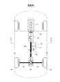
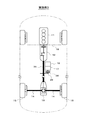
まず、図1及び図2に基づいてハイブリッド車の駆動システムの概略構成を説明する。
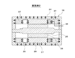
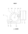
図3に示すように、MG16のケース24内には、回転軸25と一体的に回転する回転子26(ロータ)と、この回転子26の外周側に配置された固定子27(ステータ)とが設けられている。固定子27は、周方向に複数のスロット28(図4参照)を有する固定子コア29と、この固定子コア29に巻装された複数の相巻線よりなる固定子巻線30とを備えている。
車両に搭載されたバッテリ33とMG16を駆動するインバータ35とが昇圧コンバータ34を介して接続され、MG16が昇圧コンバータ34及びインバータ35を介してバッテリ33と電力を授受するようになっている。バッテリ33は、二次電池等からなる直流電源である。昇圧コンバータ34は、バッテリ33の直流電圧を昇圧してインバータ35の入力電圧をバッテリ33の直流電圧よりも高くする。インバータ35は、昇圧コンバータ34によって昇圧された直流電圧を交流電圧に変換してMG16を駆動する。
Tmax ×GRtotal >IW×1.05×Rtyre …(1)
Pmax >|20.61×(−0.79)×IW| …(2)
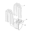
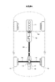
図9は、ディファレンシャルギヤ機構13を車両上方から見た図面である。図10は、図9のB−B断面を車両左側方向から見た図面である。
プロペラシャフト39の出力軸はベベルギア391に連結されている。そして、このベベルギア391は、ディファレンシャルギヤ機構13の構成要素であるリングギア131に噛み合っている。このリングギア131は駆動軸14と同軸上に配置された周知の構成である。
ここで、プロペラシャフト39の出力側の端部に位置するベベルギア391は、減速機17の出力軸171に直接連結されている。つまりエンジン11によりプロペラシャフト39に伝達された動力は減速機17にも伝達され、また逆にMG16により減速機17に伝達された動力はプロペラシャフト39にも伝達される構造である。
ユニットケース133は、前述のリングギア131やディファレンシャルギヤ132を内部に収容している。また、ユニットケース133には、プロペラシャフト39やドライブシャフト14、減速機17の出力軸171が貫通する穴が設けられている。
また、図10に示すように、ドライブシャフト14は、減速機17の出力軸171よりも車両上方に配置されている。
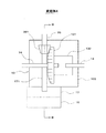
本実施例5では、図11及び図12に示すように、減速機17がディファレンシャルギヤ機構13を介して、プロペラシャフト39の出力軸に連結されている。言い換えると、前述の実施例4の様にプロペラシャフト39と減速機17とが直接連結された構造ではなく、減速機17とプロペラシャフト39とが分断された構造である。
なお、MG16及び減速機17は、ディファレンシャルギヤ機構13のユニットケース13に固定されている点は前述の実施例4と同一である。
Claims (13)
- 車両の動力源となるエンジン(11)と、該エンジンに接続された変速機(12)とを備え、前記エンジンの出力軸の軸方向が前記車両の前後方向となるように前記エンジン及び前記変速機が縦置きで配置された車両の駆動装置において、
前記車両の動力源となるモータジェネレータ(以下「MG」と表記する)(16)と、該MGに接続された減速機(17)とを備え、
前記エンジンが収容されたエンジンルームの外側に前記MG及び前記減速機が配置され、前記変速機の出力軸の動力を車輪(15)の駆動軸(14)に伝達する動力伝達系に前記減速機の出力軸が動力伝達可能に連結されていることを特徴とする車両の駆動装置。 - 前記MGのケース(24)内には、液状の冷媒(32)が前記MGの外部と循環しないように封入されていることを特徴とする請求項1に記載の車両の駆動装置。
- 前記MGの固定子巻線(30)は、複数の導体セグメント(31)を接合して形成されたセグメント型の巻線であることを特徴とする請求項2に記載の車両の駆動装置。
- 前記冷媒は、絶縁性を有することを特徴とする請求項2又は3に記載の車両の駆動装置。
- 前記MGのケース内には、該MGの少なくとも回転子(26)の外周部底面側が浸る位置まで前記冷媒が貯溜されていることを特徴とする請求項2乃至4のいずれかに記載の車両の駆動装置。
- 前記MGのケース内には、該MGの少なくとも固定子巻線のコイルエンド部と前記ケースの内面とに接触するように放熱用の固体(37)が配置されていることを特徴とする請求項1に記載の車両の駆動装置。
- 前記MGの固定子巻線(30)は、複数の導体セグメント(31)を接合して形成されたセグメント型の巻線であることを特徴とする請求項6に記載の車両の駆動装置。
- 前記固体は、絶縁性を有することを特徴とする請求項6又は7に記載の車両の駆動装置。
- 前記固体は、前記MGの回転部材(25,26)に接触しないように配置されていることを特徴とする請求項6乃至8のいずれかに記載の車両の駆動装置。
- 前記車両に搭載されたバッテリ(33)と、前記MGを駆動するインバータ(35)と、前記バッテリの電圧を昇圧して前記インバータの入力電圧を前記バッテリの電圧よりも高くする昇圧コンバータ(34)とを備えていることを特徴とする請求項1乃至9のいずれかに記載の車両の駆動装置。
- 前記MGの最大トルクTmax と、前記MGの最大出力Pmax と、前記減速機の減速比と最終減速比で決まる総合減速比GRtotal と、前記車両の重量IWと、前記車両のタイヤ半径Rtyreとが、下記(1)式及び下記(2)式の関係を満たすように、前記最大トルクTmax と前記最大出力Pmax と前記総合減速比GRtotal とが設定されていることを特徴とする請求項1乃至10のいずれかに記載の車両の駆動装置。
Tmax ×GRtotal >IW×1.05×Rtyre…(1)
Pmax >|20.61×(−0.79)×IW|…(2) - 前記車両のフロアパネル(21)に形成されたフロアトンネル(22)内に前記MG及び前記減速機の少なくとも上部側が収容されると共に前記MG及び前記減速機の最下面が前記フロアパネル及び組付部品(23)を含む前記車両の最下面よりも上方に位置するように前記MG及び前記減速機の外径が設定されていることを特徴とする請求項1乃至11のいずれかに記載の車両の駆動装置。
- 前記減速機の出力軸と前記動力伝達系との間にクラッチ(38)が設けられていることを特徴とする請求項1乃至12のいずれかに記載の車両の駆動装置。
Priority Applications (4)
| Application Number | Priority Date | Filing Date | Title |
|---|---|---|---|
| DE112016003612.4T DE112016003612T5 (de) | 2015-08-07 | 2016-07-22 | Vorrichtung zum Antreiben eines Fahrzeugs |
| US15/748,592 US20190001802A1 (en) | 2015-08-07 | 2016-07-22 | Device for driving vehicle |
| PCT/JP2016/071496 WO2017026242A1 (ja) | 2015-08-07 | 2016-07-22 | 車両の駆動装置 |
| CN201680045597.9A CN107921857A (zh) | 2015-08-07 | 2016-07-22 | 汽车驱动装置 |
Applications Claiming Priority (2)
| Application Number | Priority Date | Filing Date | Title |
|---|---|---|---|
| JP2015156831 | 2015-08-07 | ||
| JP2015156831 | 2015-08-07 |
Publications (2)
| Publication Number | Publication Date |
|---|---|
| JP2017036026A true JP2017036026A (ja) | 2017-02-16 |
| JP2017036026A5 JP2017036026A5 (ja) | 2017-11-16 |
Family
ID=58047148
Family Applications (1)
| Application Number | Title | Priority Date | Filing Date |
|---|---|---|---|
| JP2016021262A Pending JP2017036026A (ja) | 2015-08-07 | 2016-02-05 | 車両の駆動装置 |
Country Status (4)
| Country | Link |
|---|---|
| US (1) | US20190001802A1 (ja) |
| JP (1) | JP2017036026A (ja) |
| CN (1) | CN107921857A (ja) |
| DE (1) | DE112016003612T5 (ja) |
Cited By (3)
| Publication number | Priority date | Publication date | Assignee | Title |
|---|---|---|---|---|
| JPWO2018190124A1 (ja) * | 2017-04-13 | 2020-02-27 | パナソニックIpマネジメント株式会社 | コイル及びそれを用いたモータ |
| WO2023167195A1 (ja) * | 2022-03-02 | 2023-09-07 | ニデック株式会社 | モータ、電動車両 |
| KR102619367B1 (ko) * | 2023-05-26 | 2023-12-29 | 윤주성 | 하이브리드 차량 |
Families Citing this family (3)
| Publication number | Priority date | Publication date | Assignee | Title |
|---|---|---|---|---|
| CN106537733A (zh) * | 2014-07-25 | 2017-03-22 | 三菱电机株式会社 | 旋转电机 |
| CN111546881A (zh) * | 2020-05-26 | 2020-08-18 | 湖南行必达网联科技有限公司 | 车辆发电系统及发电控制方法 |
| JP7447872B2 (ja) * | 2021-06-21 | 2024-03-12 | トヨタ自動車株式会社 | 電力装置 |
Citations (16)
| Publication number | Priority date | Publication date | Assignee | Title |
|---|---|---|---|---|
| JPH0995149A (ja) * | 1995-09-29 | 1997-04-08 | Fuji Heavy Ind Ltd | ハイブリッド自動車の駆動装置 |
| JPH1199838A (ja) * | 1997-09-30 | 1999-04-13 | Fuji Heavy Ind Ltd | ハイブリッド自動車の駆動装置 |
| JP2001173762A (ja) * | 1999-10-05 | 2001-06-26 | Aisin Aw Co Ltd | ドライブユニットの潤滑装置 |
| JP2002125337A (ja) * | 2000-10-17 | 2002-04-26 | Mitsubishi Electric Corp | 車両用交流発電機 |
| JP2004048939A (ja) * | 2002-07-12 | 2004-02-12 | Denso Corp | コイルエンド接触冷却型回転電機 |
| JP2004357432A (ja) * | 2003-05-29 | 2004-12-16 | Toyota Motor Corp | 電動機ユニットおよびこれを備える車両 |
| JP2005028968A (ja) * | 2003-07-10 | 2005-02-03 | Fuji Heavy Ind Ltd | 車両用走行装置 |
| JP2005145334A (ja) * | 2003-11-18 | 2005-06-09 | Fuji Heavy Ind Ltd | ハイブリッド車両の駆動力制御装置 |
| US20060030450A1 (en) * | 2004-08-09 | 2006-02-09 | Kyle Ronald L | Hybrid vehicle formed by converting a conventional IC engine powered vehicle and method of such conversion |
| JP2006123896A (ja) * | 2004-10-29 | 2006-05-18 | American Axle & Manufacturing Inc | 車両用の車軸部および自動車の推進方法 |
| JP2008168783A (ja) * | 2007-01-11 | 2008-07-24 | Hitachi Ltd | 車両駆動装置 |
| JP2008306861A (ja) * | 2007-06-08 | 2008-12-18 | Komatsu Ltd | モータ利用機械 |
| JP2011037296A (ja) * | 2009-08-06 | 2011-02-24 | Mazda Motor Corp | 車両用駆動装置の構成方法 |
| US20130075183A1 (en) * | 2011-09-23 | 2013-03-28 | Yoshitaka KOCHIDOMARI | Vehicle With Electric Transaxle |
| JP2015196413A (ja) * | 2014-03-31 | 2015-11-09 | スズキ株式会社 | ハイブリッド四輪駆動車 |
| JP2017030594A (ja) * | 2015-08-03 | 2017-02-09 | いすゞ自動車株式会社 | ハイブリッド車両及びその制御方法 |
Family Cites Families (13)
| Publication number | Priority date | Publication date | Assignee | Title |
|---|---|---|---|---|
| US6554088B2 (en) * | 1998-09-14 | 2003-04-29 | Paice Corporation | Hybrid vehicles |
| JP2005306137A (ja) * | 2004-04-20 | 2005-11-04 | Tochigi Fuji Ind Co Ltd | ハイブリッド車両 |
| US20100044129A1 (en) * | 2004-08-09 | 2010-02-25 | Hybrid Electric Conversion Co., Llc | Hybrid vehicle formed by converting a conventional ic engine powered vehicle and method of such conversion |
| US7780562B2 (en) * | 2006-01-09 | 2010-08-24 | General Electric Company | Hybrid vehicle and method of assembling same |
| JP4572907B2 (ja) * | 2007-03-29 | 2010-11-04 | トヨタ自動車株式会社 | モータ制御装置、制御方法及び制御プログラム |
| DE112012004494T5 (de) * | 2011-10-27 | 2014-07-17 | Toyota Jidosha Kabushiki Kaisha | Segmentspule, Verfahren zur Herstellung der Segmentspule und Stator mit der Segmentspule |
| JP5483293B2 (ja) * | 2011-11-29 | 2014-05-07 | 富士重工業株式会社 | ハイブリッド自動車の車体構造 |
| JP5737273B2 (ja) * | 2012-11-15 | 2015-06-17 | 株式会社デンソー | 固定子巻線、および、固定子巻線の製造方法 |
| JP5896250B2 (ja) * | 2013-09-18 | 2016-03-30 | 株式会社デンソー | 回転電機の固定子 |
| DE102013019901A1 (de) * | 2013-11-28 | 2015-05-28 | Audi Ag | Antriebsvorrichtung für ein hybridgetriebenes Kraftfahrzeug |
| JP6370058B2 (ja) | 2014-02-24 | 2018-08-08 | 株式会社ナガセビューティケァ | ルブソシドの製造方法 |
| JP6137552B2 (ja) * | 2014-07-08 | 2017-05-31 | 株式会社デンソー | 回転電機 |
| JP6044691B2 (ja) | 2015-10-01 | 2016-12-14 | 国立研究開発法人情報通信研究機構 | 論理推論システム、計算学習装置および論理推論方法 |
-
2016
- 2016-02-05 JP JP2016021262A patent/JP2017036026A/ja active Pending
- 2016-07-22 DE DE112016003612.4T patent/DE112016003612T5/de not_active Ceased
- 2016-07-22 CN CN201680045597.9A patent/CN107921857A/zh active Pending
- 2016-07-22 US US15/748,592 patent/US20190001802A1/en not_active Abandoned
Patent Citations (16)
| Publication number | Priority date | Publication date | Assignee | Title |
|---|---|---|---|---|
| JPH0995149A (ja) * | 1995-09-29 | 1997-04-08 | Fuji Heavy Ind Ltd | ハイブリッド自動車の駆動装置 |
| JPH1199838A (ja) * | 1997-09-30 | 1999-04-13 | Fuji Heavy Ind Ltd | ハイブリッド自動車の駆動装置 |
| JP2001173762A (ja) * | 1999-10-05 | 2001-06-26 | Aisin Aw Co Ltd | ドライブユニットの潤滑装置 |
| JP2002125337A (ja) * | 2000-10-17 | 2002-04-26 | Mitsubishi Electric Corp | 車両用交流発電機 |
| JP2004048939A (ja) * | 2002-07-12 | 2004-02-12 | Denso Corp | コイルエンド接触冷却型回転電機 |
| JP2004357432A (ja) * | 2003-05-29 | 2004-12-16 | Toyota Motor Corp | 電動機ユニットおよびこれを備える車両 |
| JP2005028968A (ja) * | 2003-07-10 | 2005-02-03 | Fuji Heavy Ind Ltd | 車両用走行装置 |
| JP2005145334A (ja) * | 2003-11-18 | 2005-06-09 | Fuji Heavy Ind Ltd | ハイブリッド車両の駆動力制御装置 |
| US20060030450A1 (en) * | 2004-08-09 | 2006-02-09 | Kyle Ronald L | Hybrid vehicle formed by converting a conventional IC engine powered vehicle and method of such conversion |
| JP2006123896A (ja) * | 2004-10-29 | 2006-05-18 | American Axle & Manufacturing Inc | 車両用の車軸部および自動車の推進方法 |
| JP2008168783A (ja) * | 2007-01-11 | 2008-07-24 | Hitachi Ltd | 車両駆動装置 |
| JP2008306861A (ja) * | 2007-06-08 | 2008-12-18 | Komatsu Ltd | モータ利用機械 |
| JP2011037296A (ja) * | 2009-08-06 | 2011-02-24 | Mazda Motor Corp | 車両用駆動装置の構成方法 |
| US20130075183A1 (en) * | 2011-09-23 | 2013-03-28 | Yoshitaka KOCHIDOMARI | Vehicle With Electric Transaxle |
| JP2015196413A (ja) * | 2014-03-31 | 2015-11-09 | スズキ株式会社 | ハイブリッド四輪駆動車 |
| JP2017030594A (ja) * | 2015-08-03 | 2017-02-09 | いすゞ自動車株式会社 | ハイブリッド車両及びその制御方法 |
Cited By (4)
| Publication number | Priority date | Publication date | Assignee | Title |
|---|---|---|---|---|
| JPWO2018190124A1 (ja) * | 2017-04-13 | 2020-02-27 | パナソニックIpマネジメント株式会社 | コイル及びそれを用いたモータ |
| US11489387B2 (en) | 2017-04-13 | 2022-11-01 | Panasonic Intellectual Property Management Co., Ltd. | Coil and motor using same |
| WO2023167195A1 (ja) * | 2022-03-02 | 2023-09-07 | ニデック株式会社 | モータ、電動車両 |
| KR102619367B1 (ko) * | 2023-05-26 | 2023-12-29 | 윤주성 | 하이브리드 차량 |
Also Published As
| Publication number | Publication date |
|---|---|
| CN107921857A (zh) | 2018-04-17 |
| US20190001802A1 (en) | 2019-01-03 |
| DE112016003612T5 (de) | 2018-05-03 |
Similar Documents
| Publication | Publication Date | Title |
|---|---|---|
| JP2017036026A (ja) | 車両の駆動装置 | |
| JP3536837B2 (ja) | ハイブリッド車両用駆動装置 | |
| JP4218671B2 (ja) | ハイブリッド車両の動力出力装置 | |
| JP2008072813A (ja) | 車両の駆動装置 | |
| KR20060087412A (ko) | 하이브리드 차량 | |
| JP2009262857A (ja) | 駆動装置 | |
| JP2012096738A (ja) | 冷却装置 | |
| JP7103165B2 (ja) | 電動車両 | |
| JP2007161111A (ja) | 車両の駆動装置 | |
| JP4968543B2 (ja) | 駆動装置 | |
| JP2008256075A (ja) | 動力伝達装置 | |
| JP6662359B2 (ja) | ハイブリッド車両の駆動力制御装置 | |
| JP6390547B2 (ja) | 車両の駆動装置 | |
| JP2011093458A (ja) | ハイブリッド車両の車両構造 | |
| JP2009241910A (ja) | インホイールモータの冷却構造 | |
| US10843576B2 (en) | Electric vehicle | |
| WO2019202945A1 (ja) | モータユニット | |
| WO2017026242A1 (ja) | 車両の駆動装置 | |
| JP6693604B2 (ja) | 四輪駆動車の動力伝達装置 | |
| JP2006264463A (ja) | ハイブリッド車両の駆動装置 | |
| US20230039195A1 (en) | Motor unit and electric car | |
| JP2023049661A (ja) | 電動パワーユニット | |
| JP2009261072A (ja) | 車両用電動機 | |
| JP2015008595A (ja) | 電動車両用機電一体型駆動装置 | |
| KR20140071580A (ko) | 전기자동차 |
Legal Events
| Date | Code | Title | Description |
|---|---|---|---|
| RD04 | Notification of resignation of power of attorney |
Free format text: JAPANESE INTERMEDIATE CODE: A7424 Effective date: 20160307 |
|
| RD03 | Notification of appointment of power of attorney |
Free format text: JAPANESE INTERMEDIATE CODE: A7423 Effective date: 20160309 |
|
| A521 | Request for written amendment filed |
Free format text: JAPANESE INTERMEDIATE CODE: A523 Effective date: 20171006 |
|
| A621 | Written request for application examination |
Free format text: JAPANESE INTERMEDIATE CODE: A621 Effective date: 20171006 |
|
| A131 | Notification of reasons for refusal |
Free format text: JAPANESE INTERMEDIATE CODE: A131 Effective date: 20180828 |
|
| A521 | Request for written amendment filed |
Free format text: JAPANESE INTERMEDIATE CODE: A523 Effective date: 20181009 |
|
| A131 | Notification of reasons for refusal |
Free format text: JAPANESE INTERMEDIATE CODE: A131 Effective date: 20190205 |
|
| A521 | Request for written amendment filed |
Free format text: JAPANESE INTERMEDIATE CODE: A523 Effective date: 20190328 |
|
| A131 | Notification of reasons for refusal |
Free format text: JAPANESE INTERMEDIATE CODE: A131 Effective date: 20190910 |
|
| A02 | Decision of refusal |
Free format text: JAPANESE INTERMEDIATE CODE: A02 Effective date: 20200331 |