JP2017036026A - Driving apparatus of vehicle - Google Patents
Driving apparatus of vehicle Download PDFInfo
- Publication number
- JP2017036026A JP2017036026A JP2016021262A JP2016021262A JP2017036026A JP 2017036026 A JP2017036026 A JP 2017036026A JP 2016021262 A JP2016021262 A JP 2016021262A JP 2016021262 A JP2016021262 A JP 2016021262A JP 2017036026 A JP2017036026 A JP 2017036026A
- Authority
- JP
- Japan
- Prior art keywords
- vehicle
- speed reducer
- engine
- case
- drive device
- Prior art date
- Legal status (The legal status is an assumption and is not a legal conclusion. Google has not performed a legal analysis and makes no representation as to the accuracy of the status listed.)
- Pending
Links
Images


Classifications
-
- B—PERFORMING OPERATIONS; TRANSPORTING
- B60—VEHICLES IN GENERAL
- B60K—ARRANGEMENT OR MOUNTING OF PROPULSION UNITS OR OF TRANSMISSIONS IN VEHICLES; ARRANGEMENT OR MOUNTING OF PLURAL DIVERSE PRIME-MOVERS IN VEHICLES; AUXILIARY DRIVES FOR VEHICLES; INSTRUMENTATION OR DASHBOARDS FOR VEHICLES; ARRANGEMENTS IN CONNECTION WITH COOLING, AIR INTAKE, GAS EXHAUST OR FUEL SUPPLY OF PROPULSION UNITS IN VEHICLES
- B60K1/00—Arrangement or mounting of electrical propulsion units
- B60K1/04—Arrangement or mounting of electrical propulsion units of the electric storage means for propulsion
-
- B—PERFORMING OPERATIONS; TRANSPORTING
- B60—VEHICLES IN GENERAL
- B60K—ARRANGEMENT OR MOUNTING OF PROPULSION UNITS OR OF TRANSMISSIONS IN VEHICLES; ARRANGEMENT OR MOUNTING OF PLURAL DIVERSE PRIME-MOVERS IN VEHICLES; AUXILIARY DRIVES FOR VEHICLES; INSTRUMENTATION OR DASHBOARDS FOR VEHICLES; ARRANGEMENTS IN CONNECTION WITH COOLING, AIR INTAKE, GAS EXHAUST OR FUEL SUPPLY OF PROPULSION UNITS IN VEHICLES
- B60K11/00—Arrangement in connection with cooling of propulsion units
- B60K11/02—Arrangement in connection with cooling of propulsion units with liquid cooling
-
- B—PERFORMING OPERATIONS; TRANSPORTING
- B60—VEHICLES IN GENERAL
- B60K—ARRANGEMENT OR MOUNTING OF PROPULSION UNITS OR OF TRANSMISSIONS IN VEHICLES; ARRANGEMENT OR MOUNTING OF PLURAL DIVERSE PRIME-MOVERS IN VEHICLES; AUXILIARY DRIVES FOR VEHICLES; INSTRUMENTATION OR DASHBOARDS FOR VEHICLES; ARRANGEMENTS IN CONNECTION WITH COOLING, AIR INTAKE, GAS EXHAUST OR FUEL SUPPLY OF PROPULSION UNITS IN VEHICLES
- B60K17/00—Arrangement or mounting of transmissions in vehicles
- B60K17/04—Arrangement or mounting of transmissions in vehicles characterised by arrangement, location, or kind of gearing
- B60K17/16—Arrangement or mounting of transmissions in vehicles characterised by arrangement, location, or kind of gearing of differential gearing
-
- B—PERFORMING OPERATIONS; TRANSPORTING
- B60—VEHICLES IN GENERAL
- B60K—ARRANGEMENT OR MOUNTING OF PROPULSION UNITS OR OF TRANSMISSIONS IN VEHICLES; ARRANGEMENT OR MOUNTING OF PLURAL DIVERSE PRIME-MOVERS IN VEHICLES; AUXILIARY DRIVES FOR VEHICLES; INSTRUMENTATION OR DASHBOARDS FOR VEHICLES; ARRANGEMENTS IN CONNECTION WITH COOLING, AIR INTAKE, GAS EXHAUST OR FUEL SUPPLY OF PROPULSION UNITS IN VEHICLES
- B60K6/00—Arrangement or mounting of plural diverse prime-movers for mutual or common propulsion, e.g. hybrid propulsion systems comprising electric motors and internal combustion engines ; Control systems therefor, i.e. systems controlling two or more prime movers, or controlling one of these prime movers and any of the transmission, drive or drive units Informative references: mechanical gearings with secondary electric drive F16H3/72; arrangements for handling mechanical energy structurally associated with the dynamo-electric machine H02K7/00; machines comprising structurally interrelated motor and generator parts H02K51/00; dynamo-electric machines not otherwise provided for in H02K see H02K99/00
- B60K6/20—Arrangement or mounting of plural diverse prime-movers for mutual or common propulsion, e.g. hybrid propulsion systems comprising electric motors and internal combustion engines ; Control systems therefor, i.e. systems controlling two or more prime movers, or controlling one of these prime movers and any of the transmission, drive or drive units Informative references: mechanical gearings with secondary electric drive F16H3/72; arrangements for handling mechanical energy structurally associated with the dynamo-electric machine H02K7/00; machines comprising structurally interrelated motor and generator parts H02K51/00; dynamo-electric machines not otherwise provided for in H02K see H02K99/00 the prime-movers consisting of electric motors and internal combustion engines, e.g. HEVs
- B60K6/22—Arrangement or mounting of plural diverse prime-movers for mutual or common propulsion, e.g. hybrid propulsion systems comprising electric motors and internal combustion engines ; Control systems therefor, i.e. systems controlling two or more prime movers, or controlling one of these prime movers and any of the transmission, drive or drive units Informative references: mechanical gearings with secondary electric drive F16H3/72; arrangements for handling mechanical energy structurally associated with the dynamo-electric machine H02K7/00; machines comprising structurally interrelated motor and generator parts H02K51/00; dynamo-electric machines not otherwise provided for in H02K see H02K99/00 the prime-movers consisting of electric motors and internal combustion engines, e.g. HEVs characterised by apparatus, components or means specially adapted for HEVs
- B60K6/24—Arrangement or mounting of plural diverse prime-movers for mutual or common propulsion, e.g. hybrid propulsion systems comprising electric motors and internal combustion engines ; Control systems therefor, i.e. systems controlling two or more prime movers, or controlling one of these prime movers and any of the transmission, drive or drive units Informative references: mechanical gearings with secondary electric drive F16H3/72; arrangements for handling mechanical energy structurally associated with the dynamo-electric machine H02K7/00; machines comprising structurally interrelated motor and generator parts H02K51/00; dynamo-electric machines not otherwise provided for in H02K see H02K99/00 the prime-movers consisting of electric motors and internal combustion engines, e.g. HEVs characterised by apparatus, components or means specially adapted for HEVs characterised by the combustion engines
-
- B—PERFORMING OPERATIONS; TRANSPORTING
- B60—VEHICLES IN GENERAL
- B60K—ARRANGEMENT OR MOUNTING OF PROPULSION UNITS OR OF TRANSMISSIONS IN VEHICLES; ARRANGEMENT OR MOUNTING OF PLURAL DIVERSE PRIME-MOVERS IN VEHICLES; AUXILIARY DRIVES FOR VEHICLES; INSTRUMENTATION OR DASHBOARDS FOR VEHICLES; ARRANGEMENTS IN CONNECTION WITH COOLING, AIR INTAKE, GAS EXHAUST OR FUEL SUPPLY OF PROPULSION UNITS IN VEHICLES
- B60K6/00—Arrangement or mounting of plural diverse prime-movers for mutual or common propulsion, e.g. hybrid propulsion systems comprising electric motors and internal combustion engines ; Control systems therefor, i.e. systems controlling two or more prime movers, or controlling one of these prime movers and any of the transmission, drive or drive units Informative references: mechanical gearings with secondary electric drive F16H3/72; arrangements for handling mechanical energy structurally associated with the dynamo-electric machine H02K7/00; machines comprising structurally interrelated motor and generator parts H02K51/00; dynamo-electric machines not otherwise provided for in H02K see H02K99/00
- B60K6/20—Arrangement or mounting of plural diverse prime-movers for mutual or common propulsion, e.g. hybrid propulsion systems comprising electric motors and internal combustion engines ; Control systems therefor, i.e. systems controlling two or more prime movers, or controlling one of these prime movers and any of the transmission, drive or drive units Informative references: mechanical gearings with secondary electric drive F16H3/72; arrangements for handling mechanical energy structurally associated with the dynamo-electric machine H02K7/00; machines comprising structurally interrelated motor and generator parts H02K51/00; dynamo-electric machines not otherwise provided for in H02K see H02K99/00 the prime-movers consisting of electric motors and internal combustion engines, e.g. HEVs
- B60K6/22—Arrangement or mounting of plural diverse prime-movers for mutual or common propulsion, e.g. hybrid propulsion systems comprising electric motors and internal combustion engines ; Control systems therefor, i.e. systems controlling two or more prime movers, or controlling one of these prime movers and any of the transmission, drive or drive units Informative references: mechanical gearings with secondary electric drive F16H3/72; arrangements for handling mechanical energy structurally associated with the dynamo-electric machine H02K7/00; machines comprising structurally interrelated motor and generator parts H02K51/00; dynamo-electric machines not otherwise provided for in H02K see H02K99/00 the prime-movers consisting of electric motors and internal combustion engines, e.g. HEVs characterised by apparatus, components or means specially adapted for HEVs
- B60K6/26—Arrangement or mounting of plural diverse prime-movers for mutual or common propulsion, e.g. hybrid propulsion systems comprising electric motors and internal combustion engines ; Control systems therefor, i.e. systems controlling two or more prime movers, or controlling one of these prime movers and any of the transmission, drive or drive units Informative references: mechanical gearings with secondary electric drive F16H3/72; arrangements for handling mechanical energy structurally associated with the dynamo-electric machine H02K7/00; machines comprising structurally interrelated motor and generator parts H02K51/00; dynamo-electric machines not otherwise provided for in H02K see H02K99/00 the prime-movers consisting of electric motors and internal combustion engines, e.g. HEVs characterised by apparatus, components or means specially adapted for HEVs characterised by the motors or the generators
-
- B—PERFORMING OPERATIONS; TRANSPORTING
- B60—VEHICLES IN GENERAL
- B60K—ARRANGEMENT OR MOUNTING OF PROPULSION UNITS OR OF TRANSMISSIONS IN VEHICLES; ARRANGEMENT OR MOUNTING OF PLURAL DIVERSE PRIME-MOVERS IN VEHICLES; AUXILIARY DRIVES FOR VEHICLES; INSTRUMENTATION OR DASHBOARDS FOR VEHICLES; ARRANGEMENTS IN CONNECTION WITH COOLING, AIR INTAKE, GAS EXHAUST OR FUEL SUPPLY OF PROPULSION UNITS IN VEHICLES
- B60K6/00—Arrangement or mounting of plural diverse prime-movers for mutual or common propulsion, e.g. hybrid propulsion systems comprising electric motors and internal combustion engines ; Control systems therefor, i.e. systems controlling two or more prime movers, or controlling one of these prime movers and any of the transmission, drive or drive units Informative references: mechanical gearings with secondary electric drive F16H3/72; arrangements for handling mechanical energy structurally associated with the dynamo-electric machine H02K7/00; machines comprising structurally interrelated motor and generator parts H02K51/00; dynamo-electric machines not otherwise provided for in H02K see H02K99/00
- B60K6/20—Arrangement or mounting of plural diverse prime-movers for mutual or common propulsion, e.g. hybrid propulsion systems comprising electric motors and internal combustion engines ; Control systems therefor, i.e. systems controlling two or more prime movers, or controlling one of these prime movers and any of the transmission, drive or drive units Informative references: mechanical gearings with secondary electric drive F16H3/72; arrangements for handling mechanical energy structurally associated with the dynamo-electric machine H02K7/00; machines comprising structurally interrelated motor and generator parts H02K51/00; dynamo-electric machines not otherwise provided for in H02K see H02K99/00 the prime-movers consisting of electric motors and internal combustion engines, e.g. HEVs
- B60K6/22—Arrangement or mounting of plural diverse prime-movers for mutual or common propulsion, e.g. hybrid propulsion systems comprising electric motors and internal combustion engines ; Control systems therefor, i.e. systems controlling two or more prime movers, or controlling one of these prime movers and any of the transmission, drive or drive units Informative references: mechanical gearings with secondary electric drive F16H3/72; arrangements for handling mechanical energy structurally associated with the dynamo-electric machine H02K7/00; machines comprising structurally interrelated motor and generator parts H02K51/00; dynamo-electric machines not otherwise provided for in H02K see H02K99/00 the prime-movers consisting of electric motors and internal combustion engines, e.g. HEVs characterised by apparatus, components or means specially adapted for HEVs
- B60K6/36—Arrangement or mounting of plural diverse prime-movers for mutual or common propulsion, e.g. hybrid propulsion systems comprising electric motors and internal combustion engines ; Control systems therefor, i.e. systems controlling two or more prime movers, or controlling one of these prime movers and any of the transmission, drive or drive units Informative references: mechanical gearings with secondary electric drive F16H3/72; arrangements for handling mechanical energy structurally associated with the dynamo-electric machine H02K7/00; machines comprising structurally interrelated motor and generator parts H02K51/00; dynamo-electric machines not otherwise provided for in H02K see H02K99/00 the prime-movers consisting of electric motors and internal combustion engines, e.g. HEVs characterised by apparatus, components or means specially adapted for HEVs characterised by the transmission gearings
-
- B—PERFORMING OPERATIONS; TRANSPORTING
- B60—VEHICLES IN GENERAL
- B60K—ARRANGEMENT OR MOUNTING OF PROPULSION UNITS OR OF TRANSMISSIONS IN VEHICLES; ARRANGEMENT OR MOUNTING OF PLURAL DIVERSE PRIME-MOVERS IN VEHICLES; AUXILIARY DRIVES FOR VEHICLES; INSTRUMENTATION OR DASHBOARDS FOR VEHICLES; ARRANGEMENTS IN CONNECTION WITH COOLING, AIR INTAKE, GAS EXHAUST OR FUEL SUPPLY OF PROPULSION UNITS IN VEHICLES
- B60K6/00—Arrangement or mounting of plural diverse prime-movers for mutual or common propulsion, e.g. hybrid propulsion systems comprising electric motors and internal combustion engines ; Control systems therefor, i.e. systems controlling two or more prime movers, or controlling one of these prime movers and any of the transmission, drive or drive units Informative references: mechanical gearings with secondary electric drive F16H3/72; arrangements for handling mechanical energy structurally associated with the dynamo-electric machine H02K7/00; machines comprising structurally interrelated motor and generator parts H02K51/00; dynamo-electric machines not otherwise provided for in H02K see H02K99/00
- B60K6/20—Arrangement or mounting of plural diverse prime-movers for mutual or common propulsion, e.g. hybrid propulsion systems comprising electric motors and internal combustion engines ; Control systems therefor, i.e. systems controlling two or more prime movers, or controlling one of these prime movers and any of the transmission, drive or drive units Informative references: mechanical gearings with secondary electric drive F16H3/72; arrangements for handling mechanical energy structurally associated with the dynamo-electric machine H02K7/00; machines comprising structurally interrelated motor and generator parts H02K51/00; dynamo-electric machines not otherwise provided for in H02K see H02K99/00 the prime-movers consisting of electric motors and internal combustion engines, e.g. HEVs
- B60K6/22—Arrangement or mounting of plural diverse prime-movers for mutual or common propulsion, e.g. hybrid propulsion systems comprising electric motors and internal combustion engines ; Control systems therefor, i.e. systems controlling two or more prime movers, or controlling one of these prime movers and any of the transmission, drive or drive units Informative references: mechanical gearings with secondary electric drive F16H3/72; arrangements for handling mechanical energy structurally associated with the dynamo-electric machine H02K7/00; machines comprising structurally interrelated motor and generator parts H02K51/00; dynamo-electric machines not otherwise provided for in H02K see H02K99/00 the prime-movers consisting of electric motors and internal combustion engines, e.g. HEVs characterised by apparatus, components or means specially adapted for HEVs
- B60K6/40—Arrangement or mounting of plural diverse prime-movers for mutual or common propulsion, e.g. hybrid propulsion systems comprising electric motors and internal combustion engines ; Control systems therefor, i.e. systems controlling two or more prime movers, or controlling one of these prime movers and any of the transmission, drive or drive units Informative references: mechanical gearings with secondary electric drive F16H3/72; arrangements for handling mechanical energy structurally associated with the dynamo-electric machine H02K7/00; machines comprising structurally interrelated motor and generator parts H02K51/00; dynamo-electric machines not otherwise provided for in H02K see H02K99/00 the prime-movers consisting of electric motors and internal combustion engines, e.g. HEVs characterised by apparatus, components or means specially adapted for HEVs characterised by the assembly or relative disposition of components
-
- B—PERFORMING OPERATIONS; TRANSPORTING
- B60—VEHICLES IN GENERAL
- B60K—ARRANGEMENT OR MOUNTING OF PROPULSION UNITS OR OF TRANSMISSIONS IN VEHICLES; ARRANGEMENT OR MOUNTING OF PLURAL DIVERSE PRIME-MOVERS IN VEHICLES; AUXILIARY DRIVES FOR VEHICLES; INSTRUMENTATION OR DASHBOARDS FOR VEHICLES; ARRANGEMENTS IN CONNECTION WITH COOLING, AIR INTAKE, GAS EXHAUST OR FUEL SUPPLY OF PROPULSION UNITS IN VEHICLES
- B60K6/00—Arrangement or mounting of plural diverse prime-movers for mutual or common propulsion, e.g. hybrid propulsion systems comprising electric motors and internal combustion engines ; Control systems therefor, i.e. systems controlling two or more prime movers, or controlling one of these prime movers and any of the transmission, drive or drive units Informative references: mechanical gearings with secondary electric drive F16H3/72; arrangements for handling mechanical energy structurally associated with the dynamo-electric machine H02K7/00; machines comprising structurally interrelated motor and generator parts H02K51/00; dynamo-electric machines not otherwise provided for in H02K see H02K99/00
- B60K6/20—Arrangement or mounting of plural diverse prime-movers for mutual or common propulsion, e.g. hybrid propulsion systems comprising electric motors and internal combustion engines ; Control systems therefor, i.e. systems controlling two or more prime movers, or controlling one of these prime movers and any of the transmission, drive or drive units Informative references: mechanical gearings with secondary electric drive F16H3/72; arrangements for handling mechanical energy structurally associated with the dynamo-electric machine H02K7/00; machines comprising structurally interrelated motor and generator parts H02K51/00; dynamo-electric machines not otherwise provided for in H02K see H02K99/00 the prime-movers consisting of electric motors and internal combustion engines, e.g. HEVs
- B60K6/42—Arrangement or mounting of plural diverse prime-movers for mutual or common propulsion, e.g. hybrid propulsion systems comprising electric motors and internal combustion engines ; Control systems therefor, i.e. systems controlling two or more prime movers, or controlling one of these prime movers and any of the transmission, drive or drive units Informative references: mechanical gearings with secondary electric drive F16H3/72; arrangements for handling mechanical energy structurally associated with the dynamo-electric machine H02K7/00; machines comprising structurally interrelated motor and generator parts H02K51/00; dynamo-electric machines not otherwise provided for in H02K see H02K99/00 the prime-movers consisting of electric motors and internal combustion engines, e.g. HEVs characterised by the architecture of the hybrid electric vehicle
- B60K6/48—Parallel type
-
- B—PERFORMING OPERATIONS; TRANSPORTING
- B60—VEHICLES IN GENERAL
- B60K—ARRANGEMENT OR MOUNTING OF PROPULSION UNITS OR OF TRANSMISSIONS IN VEHICLES; ARRANGEMENT OR MOUNTING OF PLURAL DIVERSE PRIME-MOVERS IN VEHICLES; AUXILIARY DRIVES FOR VEHICLES; INSTRUMENTATION OR DASHBOARDS FOR VEHICLES; ARRANGEMENTS IN CONNECTION WITH COOLING, AIR INTAKE, GAS EXHAUST OR FUEL SUPPLY OF PROPULSION UNITS IN VEHICLES
- B60K6/00—Arrangement or mounting of plural diverse prime-movers for mutual or common propulsion, e.g. hybrid propulsion systems comprising electric motors and internal combustion engines ; Control systems therefor, i.e. systems controlling two or more prime movers, or controlling one of these prime movers and any of the transmission, drive or drive units Informative references: mechanical gearings with secondary electric drive F16H3/72; arrangements for handling mechanical energy structurally associated with the dynamo-electric machine H02K7/00; machines comprising structurally interrelated motor and generator parts H02K51/00; dynamo-electric machines not otherwise provided for in H02K see H02K99/00
- B60K6/20—Arrangement or mounting of plural diverse prime-movers for mutual or common propulsion, e.g. hybrid propulsion systems comprising electric motors and internal combustion engines ; Control systems therefor, i.e. systems controlling two or more prime movers, or controlling one of these prime movers and any of the transmission, drive or drive units Informative references: mechanical gearings with secondary electric drive F16H3/72; arrangements for handling mechanical energy structurally associated with the dynamo-electric machine H02K7/00; machines comprising structurally interrelated motor and generator parts H02K51/00; dynamo-electric machines not otherwise provided for in H02K see H02K99/00 the prime-movers consisting of electric motors and internal combustion engines, e.g. HEVs
- B60K6/50—Architecture of the driveline characterised by arrangement or kind of transmission units
- B60K6/54—Transmission for changing ratio
- B60K6/547—Transmission for changing ratio the transmission being a stepped gearing
-
- B—PERFORMING OPERATIONS; TRANSPORTING
- B60—VEHICLES IN GENERAL
- B60L—PROPULSION OF ELECTRICALLY-PROPELLED VEHICLES; SUPPLYING ELECTRIC POWER FOR AUXILIARY EQUIPMENT OF ELECTRICALLY-PROPELLED VEHICLES; ELECTRODYNAMIC BRAKE SYSTEMS FOR VEHICLES IN GENERAL; MAGNETIC SUSPENSION OR LEVITATION FOR VEHICLES; MONITORING OPERATING VARIABLES OF ELECTRICALLY-PROPELLED VEHICLES; ELECTRIC SAFETY DEVICES FOR ELECTRICALLY-PROPELLED VEHICLES
- B60L50/00—Electric propulsion with power supplied within the vehicle
- B60L50/10—Electric propulsion with power supplied within the vehicle using propulsion power supplied by engine-driven generators, e.g. generators driven by combustion engines
- B60L50/16—Electric propulsion with power supplied within the vehicle using propulsion power supplied by engine-driven generators, e.g. generators driven by combustion engines with provision for separate direct mechanical propulsion
-
- H—ELECTRICITY
- H02—GENERATION; CONVERSION OR DISTRIBUTION OF ELECTRIC POWER
- H02K—DYNAMO-ELECTRIC MACHINES
- H02K3/00—Details of windings
- H02K3/04—Windings characterised by the conductor shape, form or construction, e.g. with bar conductors
- H02K3/24—Windings characterised by the conductor shape, form or construction, e.g. with bar conductors with channels or ducts for cooling medium between the conductors
-
- H—ELECTRICITY
- H02—GENERATION; CONVERSION OR DISTRIBUTION OF ELECTRIC POWER
- H02K—DYNAMO-ELECTRIC MACHINES
- H02K3/00—Details of windings
- H02K3/32—Windings characterised by the shape, form or construction of the insulation
- H02K3/34—Windings characterised by the shape, form or construction of the insulation between conductors or between conductor and core, e.g. slot insulation
- H02K3/345—Windings characterised by the shape, form or construction of the insulation between conductors or between conductor and core, e.g. slot insulation between conductor and core, e.g. slot insulation
-
- H—ELECTRICITY
- H02—GENERATION; CONVERSION OR DISTRIBUTION OF ELECTRIC POWER
- H02K—DYNAMO-ELECTRIC MACHINES
- H02K7/00—Arrangements for handling mechanical energy structurally associated with dynamo-electric machines, e.g. structural association with mechanical driving motors or auxiliary dynamo-electric machines
- H02K7/006—Structural association of a motor or generator with the drive train of a motor vehicle
-
- H—ELECTRICITY
- H02—GENERATION; CONVERSION OR DISTRIBUTION OF ELECTRIC POWER
- H02K—DYNAMO-ELECTRIC MACHINES
- H02K7/00—Arrangements for handling mechanical energy structurally associated with dynamo-electric machines, e.g. structural association with mechanical driving motors or auxiliary dynamo-electric machines
- H02K7/10—Structural association with clutches, brakes, gears, pulleys or mechanical starters
- H02K7/116—Structural association with clutches, brakes, gears, pulleys or mechanical starters with gears
-
- H—ELECTRICITY
- H02—GENERATION; CONVERSION OR DISTRIBUTION OF ELECTRIC POWER
- H02K—DYNAMO-ELECTRIC MACHINES
- H02K9/00—Arrangements for cooling or ventilating
- H02K9/19—Arrangements for cooling or ventilating for machines with closed casing and closed-circuit cooling using a liquid cooling medium, e.g. oil
- H02K9/197—Arrangements for cooling or ventilating for machines with closed casing and closed-circuit cooling using a liquid cooling medium, e.g. oil in which the rotor or stator space is fluid-tight, e.g. to provide for different cooling media for rotor and stator
-
- B—PERFORMING OPERATIONS; TRANSPORTING
- B60—VEHICLES IN GENERAL
- B60K—ARRANGEMENT OR MOUNTING OF PROPULSION UNITS OR OF TRANSMISSIONS IN VEHICLES; ARRANGEMENT OR MOUNTING OF PLURAL DIVERSE PRIME-MOVERS IN VEHICLES; AUXILIARY DRIVES FOR VEHICLES; INSTRUMENTATION OR DASHBOARDS FOR VEHICLES; ARRANGEMENTS IN CONNECTION WITH COOLING, AIR INTAKE, GAS EXHAUST OR FUEL SUPPLY OF PROPULSION UNITS IN VEHICLES
- B60K6/00—Arrangement or mounting of plural diverse prime-movers for mutual or common propulsion, e.g. hybrid propulsion systems comprising electric motors and internal combustion engines ; Control systems therefor, i.e. systems controlling two or more prime movers, or controlling one of these prime movers and any of the transmission, drive or drive units Informative references: mechanical gearings with secondary electric drive F16H3/72; arrangements for handling mechanical energy structurally associated with the dynamo-electric machine H02K7/00; machines comprising structurally interrelated motor and generator parts H02K51/00; dynamo-electric machines not otherwise provided for in H02K see H02K99/00
- B60K6/20—Arrangement or mounting of plural diverse prime-movers for mutual or common propulsion, e.g. hybrid propulsion systems comprising electric motors and internal combustion engines ; Control systems therefor, i.e. systems controlling two or more prime movers, or controlling one of these prime movers and any of the transmission, drive or drive units Informative references: mechanical gearings with secondary electric drive F16H3/72; arrangements for handling mechanical energy structurally associated with the dynamo-electric machine H02K7/00; machines comprising structurally interrelated motor and generator parts H02K51/00; dynamo-electric machines not otherwise provided for in H02K see H02K99/00 the prime-movers consisting of electric motors and internal combustion engines, e.g. HEVs
- B60K6/42—Arrangement or mounting of plural diverse prime-movers for mutual or common propulsion, e.g. hybrid propulsion systems comprising electric motors and internal combustion engines ; Control systems therefor, i.e. systems controlling two or more prime movers, or controlling one of these prime movers and any of the transmission, drive or drive units Informative references: mechanical gearings with secondary electric drive F16H3/72; arrangements for handling mechanical energy structurally associated with the dynamo-electric machine H02K7/00; machines comprising structurally interrelated motor and generator parts H02K51/00; dynamo-electric machines not otherwise provided for in H02K see H02K99/00 the prime-movers consisting of electric motors and internal combustion engines, e.g. HEVs characterised by the architecture of the hybrid electric vehicle
- B60K6/48—Parallel type
- B60K2006/4808—Electric machine connected or connectable to gearbox output shaft
-
- B—PERFORMING OPERATIONS; TRANSPORTING
- B60—VEHICLES IN GENERAL
- B60K—ARRANGEMENT OR MOUNTING OF PROPULSION UNITS OR OF TRANSMISSIONS IN VEHICLES; ARRANGEMENT OR MOUNTING OF PLURAL DIVERSE PRIME-MOVERS IN VEHICLES; AUXILIARY DRIVES FOR VEHICLES; INSTRUMENTATION OR DASHBOARDS FOR VEHICLES; ARRANGEMENTS IN CONNECTION WITH COOLING, AIR INTAKE, GAS EXHAUST OR FUEL SUPPLY OF PROPULSION UNITS IN VEHICLES
- B60K6/00—Arrangement or mounting of plural diverse prime-movers for mutual or common propulsion, e.g. hybrid propulsion systems comprising electric motors and internal combustion engines ; Control systems therefor, i.e. systems controlling two or more prime movers, or controlling one of these prime movers and any of the transmission, drive or drive units Informative references: mechanical gearings with secondary electric drive F16H3/72; arrangements for handling mechanical energy structurally associated with the dynamo-electric machine H02K7/00; machines comprising structurally interrelated motor and generator parts H02K51/00; dynamo-electric machines not otherwise provided for in H02K see H02K99/00
- B60K6/20—Arrangement or mounting of plural diverse prime-movers for mutual or common propulsion, e.g. hybrid propulsion systems comprising electric motors and internal combustion engines ; Control systems therefor, i.e. systems controlling two or more prime movers, or controlling one of these prime movers and any of the transmission, drive or drive units Informative references: mechanical gearings with secondary electric drive F16H3/72; arrangements for handling mechanical energy structurally associated with the dynamo-electric machine H02K7/00; machines comprising structurally interrelated motor and generator parts H02K51/00; dynamo-electric machines not otherwise provided for in H02K see H02K99/00 the prime-movers consisting of electric motors and internal combustion engines, e.g. HEVs
- B60K6/42—Arrangement or mounting of plural diverse prime-movers for mutual or common propulsion, e.g. hybrid propulsion systems comprising electric motors and internal combustion engines ; Control systems therefor, i.e. systems controlling two or more prime movers, or controlling one of these prime movers and any of the transmission, drive or drive units Informative references: mechanical gearings with secondary electric drive F16H3/72; arrangements for handling mechanical energy structurally associated with the dynamo-electric machine H02K7/00; machines comprising structurally interrelated motor and generator parts H02K51/00; dynamo-electric machines not otherwise provided for in H02K see H02K99/00 the prime-movers consisting of electric motors and internal combustion engines, e.g. HEVs characterised by the architecture of the hybrid electric vehicle
- B60K6/48—Parallel type
- B60K2006/4833—Step up or reduction gearing driving generator, e.g. to operate generator in most efficient speed range
-
- B—PERFORMING OPERATIONS; TRANSPORTING
- B60—VEHICLES IN GENERAL
- B60L—PROPULSION OF ELECTRICALLY-PROPELLED VEHICLES; SUPPLYING ELECTRIC POWER FOR AUXILIARY EQUIPMENT OF ELECTRICALLY-PROPELLED VEHICLES; ELECTRODYNAMIC BRAKE SYSTEMS FOR VEHICLES IN GENERAL; MAGNETIC SUSPENSION OR LEVITATION FOR VEHICLES; MONITORING OPERATING VARIABLES OF ELECTRICALLY-PROPELLED VEHICLES; ELECTRIC SAFETY DEVICES FOR ELECTRICALLY-PROPELLED VEHICLES
- B60L2240/00—Control parameters of input or output; Target parameters
- B60L2240/40—Drive Train control parameters
- B60L2240/48—Drive Train control parameters related to transmissions
-
- B—PERFORMING OPERATIONS; TRANSPORTING
- B62—LAND VEHICLES FOR TRAVELLING OTHERWISE THAN ON RAILS
- B62D—MOTOR VEHICLES; TRAILERS
- B62D25/00—Superstructure or monocoque structure sub-units; Parts or details thereof not otherwise provided for
- B62D25/20—Floors or bottom sub-units
-
- B—PERFORMING OPERATIONS; TRANSPORTING
- B62—LAND VEHICLES FOR TRAVELLING OTHERWISE THAN ON RAILS
- B62D—MOTOR VEHICLES; TRAILERS
- B62D25/00—Superstructure or monocoque structure sub-units; Parts or details thereof not otherwise provided for
- B62D25/20—Floors or bottom sub-units
- B62D25/2009—Floors or bottom sub-units in connection with other superstructure subunits
-
- H—ELECTRICITY
- H02—GENERATION; CONVERSION OR DISTRIBUTION OF ELECTRIC POWER
- H02K—DYNAMO-ELECTRIC MACHINES
- H02K3/00—Details of windings
- H02K3/04—Windings characterised by the conductor shape, form or construction, e.g. with bar conductors
- H02K3/12—Windings characterised by the conductor shape, form or construction, e.g. with bar conductors arranged in slots
-
- Y—GENERAL TAGGING OF NEW TECHNOLOGICAL DEVELOPMENTS; GENERAL TAGGING OF CROSS-SECTIONAL TECHNOLOGIES SPANNING OVER SEVERAL SECTIONS OF THE IPC; TECHNICAL SUBJECTS COVERED BY FORMER USPC CROSS-REFERENCE ART COLLECTIONS [XRACs] AND DIGESTS
- Y02—TECHNOLOGIES OR APPLICATIONS FOR MITIGATION OR ADAPTATION AGAINST CLIMATE CHANGE
- Y02T—CLIMATE CHANGE MITIGATION TECHNOLOGIES RELATED TO TRANSPORTATION
- Y02T10/00—Road transport of goods or passengers
- Y02T10/60—Other road transportation technologies with climate change mitigation effect
- Y02T10/62—Hybrid vehicles
-
- Y—GENERAL TAGGING OF NEW TECHNOLOGICAL DEVELOPMENTS; GENERAL TAGGING OF CROSS-SECTIONAL TECHNOLOGIES SPANNING OVER SEVERAL SECTIONS OF THE IPC; TECHNICAL SUBJECTS COVERED BY FORMER USPC CROSS-REFERENCE ART COLLECTIONS [XRACs] AND DIGESTS
- Y02—TECHNOLOGIES OR APPLICATIONS FOR MITIGATION OR ADAPTATION AGAINST CLIMATE CHANGE
- Y02T—CLIMATE CHANGE MITIGATION TECHNOLOGIES RELATED TO TRANSPORTATION
- Y02T10/00—Road transport of goods or passengers
- Y02T10/60—Other road transportation technologies with climate change mitigation effect
- Y02T10/64—Electric machine technologies in electromobility
-
- Y—GENERAL TAGGING OF NEW TECHNOLOGICAL DEVELOPMENTS; GENERAL TAGGING OF CROSS-SECTIONAL TECHNOLOGIES SPANNING OVER SEVERAL SECTIONS OF THE IPC; TECHNICAL SUBJECTS COVERED BY FORMER USPC CROSS-REFERENCE ART COLLECTIONS [XRACs] AND DIGESTS
- Y02—TECHNOLOGIES OR APPLICATIONS FOR MITIGATION OR ADAPTATION AGAINST CLIMATE CHANGE
- Y02T—CLIMATE CHANGE MITIGATION TECHNOLOGIES RELATED TO TRANSPORTATION
- Y02T10/00—Road transport of goods or passengers
- Y02T10/60—Other road transportation technologies with climate change mitigation effect
- Y02T10/70—Energy storage systems for electromobility, e.g. batteries
-
- Y—GENERAL TAGGING OF NEW TECHNOLOGICAL DEVELOPMENTS; GENERAL TAGGING OF CROSS-SECTIONAL TECHNOLOGIES SPANNING OVER SEVERAL SECTIONS OF THE IPC; TECHNICAL SUBJECTS COVERED BY FORMER USPC CROSS-REFERENCE ART COLLECTIONS [XRACs] AND DIGESTS
- Y02—TECHNOLOGIES OR APPLICATIONS FOR MITIGATION OR ADAPTATION AGAINST CLIMATE CHANGE
- Y02T—CLIMATE CHANGE MITIGATION TECHNOLOGIES RELATED TO TRANSPORTATION
- Y02T10/00—Road transport of goods or passengers
- Y02T10/60—Other road transportation technologies with climate change mitigation effect
- Y02T10/7072—Electromobility specific charging systems or methods for batteries, ultracapacitors, supercapacitors or double-layer capacitors
-
- Y—GENERAL TAGGING OF NEW TECHNOLOGICAL DEVELOPMENTS; GENERAL TAGGING OF CROSS-SECTIONAL TECHNOLOGIES SPANNING OVER SEVERAL SECTIONS OF THE IPC; TECHNICAL SUBJECTS COVERED BY FORMER USPC CROSS-REFERENCE ART COLLECTIONS [XRACs] AND DIGESTS
- Y02—TECHNOLOGIES OR APPLICATIONS FOR MITIGATION OR ADAPTATION AGAINST CLIMATE CHANGE
- Y02T—CLIMATE CHANGE MITIGATION TECHNOLOGIES RELATED TO TRANSPORTATION
- Y02T10/00—Road transport of goods or passengers
- Y02T10/60—Other road transportation technologies with climate change mitigation effect
- Y02T10/72—Electric energy management in electromobility
Abstract
Description
本発明は、車両の動力源としてエンジン及びモータジェネレータを備えた車両の駆動装置に関する発明である。 The present invention relates to a vehicle drive device including an engine and a motor generator as a power source of the vehicle.
近年、低燃費、低排気エミッションの社会的要請から車両の動力源としてエンジンとモータジェネレータ(以下「MG」と表記する)とを搭載したハイブリッド車が注目されている。このようなハイブリッド車においては、例えば、特許文献1(特許第3350314号公報)に記載されたものがある。このものは、エンジンにクラッチを介して変速機を接続し、この変速機の出力軸に差動歯車(ディファレンシャルギヤ機構)を介して車輪の駆動軸を連結すると共に、差動歯車のリングギヤに四輪駆動車用のトランスファを介してMGの出力軸を連結することでMGの動力を駆動軸に伝達できるようにしている。 In recent years, a hybrid vehicle equipped with an engine and a motor generator (hereinafter referred to as “MG”) as a power source of the vehicle has attracted attention because of social demands for low fuel consumption and low exhaust emissions. Such a hybrid vehicle includes, for example, one described in Patent Document 1 (Japanese Patent No. 3350314). In this system, a transmission is connected to an engine via a clutch, a drive shaft of a wheel is connected to an output shaft of the transmission via a differential gear (differential gear mechanism), and four rings are connected to a ring gear of the differential gear. By connecting the output shaft of the MG through a transfer for a wheel drive vehicle, the power of the MG can be transmitted to the drive shaft.
ハイブリッド車において、低燃費や低排気エミッションの要求を満たすためには、エンジンとMGのうちMGの動力のみで車両を走行させるEV走行(MGの動力のみで車両を発進させるEV発進を含む)が重要な機能となる。しかし、上記特許文献1の技術では、MGの出力軸を減速機構を介さずにトランスファに直接接続した構成としているため、小型のMGでは、EV走行に必要な軸トルク(駆動軸のトルク)を発生させることができない可能性があり、ハイブリッド車の重要な機能であるEV走行の実現が困難である。また、EV走行に必要な軸トルクを発生させるには、MGを大型化する必要があり、この場合、MGの搭載スペースを確保することが困難になる。 In order to satisfy the requirements of low fuel consumption and low exhaust emissions in hybrid vehicles, EV driving (including EV starting that starts the vehicle only with MG power) of the engine and MG is performed. It becomes an important function. However, in the technique of the above-mentioned Patent Document 1, since the MG output shaft is directly connected to the transfer without using a speed reduction mechanism, in a small MG, the shaft torque (drive shaft torque) required for EV traveling is obtained. There is a possibility that it cannot be generated, and it is difficult to realize EV traveling, which is an important function of a hybrid vehicle. Further, in order to generate the shaft torque necessary for EV travel, it is necessary to increase the size of the MG, and in this case, it is difficult to secure a space for mounting the MG.
そこで、本発明が解決しようとする課題は、小型のMGでもEV走行を実現することができ、MGの搭載スペースを容易に確保することができる車両の駆動装置を提供することにある。 Therefore, the problem to be solved by the present invention is to provide a vehicle drive device that can realize EV traveling even with a small MG and can easily secure a space for mounting the MG.
上記課題を解決するために、請求項1に係る発明は、車両の動力源となるエンジン(11)と、該エンジンに接続された変速機(12)とを備え、エンジンの出力軸の軸方向が車両の前後方向となるようにエンジン及び変速機が縦置きで配置された車両の駆動装置において、車両の動力源となるモータジェネレータ(以下「MG」と表記する)(16)と、該MGに接続された減速機(17)とを備え、エンジンが収容されたエンジンルームの外側にMG及び減速機が配置され、変速機の出力軸の動力を車輪(15)の駆動軸(14)に伝達する動力伝達系に減速機の出力軸が動力伝達可能に連結されている構成としたものである。 In order to solve the above-mentioned problems, an invention according to claim 1 includes an engine (11) serving as a power source of a vehicle and a transmission (12) connected to the engine, and an axial direction of an output shaft of the engine , A motor generator (hereinafter referred to as “MG”) (16) serving as a power source of the vehicle, in the vehicle drive device in which the engine and the transmission are arranged vertically so that is in the longitudinal direction of the vehicle, the MG The MG and the speed reducer are disposed outside the engine room in which the engine is accommodated, and the power of the output shaft of the transmission is transmitted to the drive shaft (14) of the wheel (15). The output shaft of the speed reducer is connected to the power transmission system for transmission so that power can be transmitted.
この構成では、MGの動力を減速機を介して車輪の駆動軸に伝達することができるため、小型のMGでもEV走行に必要な軸トルクを発生させることができ、ハイブリッド車の重要な機能であるEV走行を実現することができる。これにより、MGを小型化することが可能となり、更に、エンジンルームの外側にMG及び減速機を配置する構成とすることで、MG及び減速機の搭載スペースを容易に確保することができる。このため、エンジン及び変速機が縦置きで配置されたエンジン車(エンジンのみを動力源とする車両)をベースとしてハイブリッド車を製造する場合でも、ベースとなるエンジン車の車体構造をあまり変更せずに、EV走行を実現可能なハイブリッド車を製造することができる。 In this configuration, the power of the MG can be transmitted to the wheel drive shaft via the speed reducer, so that even a small MG can generate the shaft torque necessary for EV travel, which is an important function of the hybrid vehicle. A certain EV traveling can be realized. Thereby, it becomes possible to reduce the size of the MG, and further, by mounting the MG and the speed reducer outside the engine room, it is possible to easily secure the space for mounting the MG and the speed reducer. For this reason, even when a hybrid vehicle is manufactured based on an engine vehicle (a vehicle that uses only the engine as a power source) in which the engine and the transmission are arranged vertically, the vehicle body structure of the engine vehicle that is the base is not significantly changed. In addition, a hybrid vehicle capable of realizing EV traveling can be manufactured.
また、次のような利点もある。MG駆動系の故障が発生した場合でも、エンジンの動力を変速機を介して駆動軸に伝達することができるため、エンジンの動力で十分に自走(自力走行)することができる。牽引等の負荷が高い条件においても、ベースとなるエンジン車と同等以上の駆動力を発揮することができる。MGがエンジンルームの外側(つまり車体の中央寄り)に配置されるため、衝突事故等を起こした場合でも、MGの損傷が低減されると共に、MGが車外に露出することを防止して感電事故の可能性も低減することができる。 There are also the following advantages. Even when a failure of the MG drive system occurs, the engine power can be transmitted to the drive shaft via the transmission, so that the engine power can be sufficiently self-running (self-running). Even under a high load such as towing, the driving force equivalent to or higher than that of the engine car as a base can be exhibited. Since the MG is located outside the engine room (that is, near the center of the vehicle body), even if a collision accident occurs, the damage to the MG is reduced and the MG is prevented from being exposed to the outside of the vehicle. Can also be reduced.
ところで、MGの動力を減速機を介して駆動軸に伝達する構成では、特に小型のMGの場合には発熱量が多くなる傾向がある。MGの発熱によりMGが過熱状態になると、MGの駆動を制限する必要が生じる。 By the way, in the configuration in which the power of the MG is transmitted to the drive shaft via the speed reducer, the amount of heat generation tends to increase particularly in the case of a small MG. When the MG is overheated due to the heat generated by the MG, it is necessary to limit the driving of the MG.
そこで、請求項2のように、MGのケース(24)内には、液状の冷媒(32)をMGの外部と循環しないように封入するようにすると良い。このようにすれば、MG内部の熱を冷媒を介して効率的にケースに伝導させてMGの外部に放出することができ、MGを効果的に冷却することができる。これにより、MGの過熱を防止することができ、より高負荷、長時間のMGの駆動が可能になる。また、MGのケース内で飛散・充満する冷媒が固定子や回転子の冷却も促進するため、MGのケース内に複雑な流路を設けることなく、低コストで高い冷却効果を得ることができる。しかも、冷媒をMGの外部と循環させる循環路を設ける必要がなく、車両への搭載性を向上させることができる。また、MGが高速回転する際に必要な軸受への潤滑油として冷媒を供給することができるため、MGの冷却効果を高めながらMGの機械的寿命も延長することができる。更に、MGの回転に伴う振動を減衰して静粛性を向上させることもできる。 Therefore, as in claim 2, it is preferable to enclose the liquid refrigerant (32) in the MG case (24) so as not to circulate outside the MG. If it does in this way, the heat inside MG can be efficiently conducted to a case via a refrigerant, can be emitted outside MG, and MG can be cooled effectively. As a result, overheating of the MG can be prevented, and the MG can be driven for a higher load and longer time. In addition, since the refrigerant scattered and filled in the MG case also promotes cooling of the stator and the rotor, a high cooling effect can be obtained at low cost without providing a complicated flow path in the MG case. . In addition, it is not necessary to provide a circulation path for circulating the refrigerant to the outside of the MG, and the mounting property on the vehicle can be improved. Further, since the refrigerant can be supplied as lubricating oil to the bearing required when the MG rotates at a high speed, the mechanical life of the MG can be extended while enhancing the cooling effect of the MG. Furthermore, the vibration associated with the rotation of the MG can be attenuated to improve quietness.
この場合、請求項3のように、MGの固定子巻線(30)は、複数の導体セグメント(31)を接合して形成されたセグメント型の巻線にすると良い。このようにすれば、固定子巻線の巻線間(つまり導体セグメント間)に適度な隙間が形成され、その隙間に冷媒が容易に入り込むことにより、冷媒を介した固定子巻線とケースとの間の熱伝達効率を向上させることができる。 In this case, as in claim 3, the MG stator winding (30) is preferably a segment-type winding formed by joining a plurality of conductor segments (31). In this way, an appropriate gap is formed between the windings of the stator winding (that is, between the conductor segments), and the refrigerant easily enters the gap, so that the stator winding and the case through the refrigerant The heat transfer efficiency between the two can be improved.
また、請求項4のように、冷媒として、絶縁性を有するものを用いるようにすると良い。このようにすれば、MGのケース内の通電部品の絶縁被膜に不具合が発生した場合や通電部品が損傷した場合でも、MGのケース内での冷媒を介しての短絡を防止することができる。 Moreover, as in claim 4, it is preferable to use an insulating material as the refrigerant. In this way, even when a failure occurs in the insulating coating of the energized component in the MG case or when the energized component is damaged, a short circuit through the refrigerant in the MG case can be prevented.
更に、請求項5のように、MGのケース内には、該MGの少なくとも回転子(26)の外周部底面側が浸る位置まで冷媒を貯溜するようにすると良い。このようにすれば、回転子の回転により冷媒が掻き上げられて空気と混ざり合い、回転する回転子と冷媒とが接触する際のせん断抵抗を低下させて、回転子の回転抵抗を低下せることができ、MGの効率を向上させることができる。また、空気と混ざり合った泡状の冷媒がMGのケース内の隅々まで行き渡って、ケース表面全体を伝熱や放熱のために最大限に利用することができると共に、冷媒が巻線のコイルエンド部、中性点、引き出し線にも掛かることによって優れた冷却効果を得ることができる。 Further, as in claim 5, it is preferable that the refrigerant is stored in the MG case up to a position where at least the bottom surface side of the outer periphery of the rotor (26) of the MG is immersed. In this way, the rotation of the rotor causes the refrigerant to be scraped up and mixed with the air, reducing the shear resistance when the rotating rotor and the refrigerant are in contact with each other, thereby reducing the rotation resistance of the rotor. MG efficiency can be improved. In addition, the foamed refrigerant mixed with air can reach every corner of the MG case, and the entire surface of the case can be used for heat transfer and heat dissipation. An excellent cooling effect can be obtained by applying to the end portion, the neutral point, and the lead wire.
或は、請求項6のように、MGのケース内には、該MGの少なくとも固定子巻線のコイルエンド部とケースの内面とに接触するように放熱用の固体(37)を配置するようにしても良い。このようにすれば、MGの固定子巻線のコイルエンド部の熱を固体を介して効率的にケースに伝導させてMGの外部に放出することができ、MGを効果的に冷却することができる。これにより、MGの過熱を防止することができ、より高負荷、長時間のMGの駆動が可能になる。また、固定子巻線のコイルエンド部を固体で保持することができるため、コイルエンド部が励磁により振動して騒音が発生することを防止することができる。更に、エンジンや車体の振動によりコイルエンド部やその絶縁被膜が損傷することを防止することができる。 Alternatively, as in claim 6, a heat dissipating solid (37) is disposed in the MG case so as to contact at least the coil end portion of the stator winding of the MG and the inner surface of the case. Anyway. In this way, the heat of the coil end portion of the stator winding of the MG can be efficiently conducted to the case through the solid and released to the outside of the MG, and the MG can be effectively cooled. it can. As a result, overheating of the MG can be prevented, and the MG can be driven for a higher load and longer time. Further, since the coil end portion of the stator winding can be held in a solid state, it is possible to prevent the coil end portion from vibrating due to excitation and generating noise. Furthermore, it is possible to prevent the coil end portion and its insulating coating from being damaged by the vibration of the engine or the vehicle body.
この場合、請求項7のように、MGの固定子巻線(30)は、複数の導体セグメント(31)を接合して形成されたセグメント型の巻線にすると良い。このようにすれば、固定子巻線の巻線間(つまり導体セグメント間)に適度な隙間が形成され、固体の成形時にその隙間に液状の材料が容易に入り込むことにより、固体を介した固定子巻線とケースとの間の熱伝達効率を向上させることができる。 In this case, as in the seventh aspect, the stator winding (30) of the MG is preferably a segment type winding formed by joining a plurality of conductor segments (31). In this way, an appropriate gap is formed between the windings of the stator winding (that is, between the conductor segments), and the liquid material can easily enter the gap during molding of the solid, so that fixing via the solid is possible. The heat transfer efficiency between the child winding and the case can be improved.
また、請求項8のように、固体として、絶縁性を有するものを用いるようにすると良い。このようにすれば、コイルエンド部の絶縁被膜に不具合が発生した場合でも、MGのケース内での固体を介しての短絡を防止することができる。また、絶縁性の固体の存在によりコイルエンド部とケースとの間の絶縁性が高められるため、コイルエンド部とケースの距離を縮めることができ、ケースへの放熱効果を高めることができると共に、MGを小型化することができる。 Further, as in claim 8, it is preferable to use a solid material having an insulating property. In this way, even when a failure occurs in the insulating film at the coil end portion, it is possible to prevent a short circuit through the solid in the MG case. In addition, since the insulation between the coil end portion and the case is enhanced by the presence of the insulating solid, the distance between the coil end portion and the case can be reduced, and the heat dissipation effect to the case can be enhanced. MG can be reduced in size.
更に、請求項9のように、固体は、MGの回転部材(25,26)に接触しないように配置するようにすると良い。このようにすれば、MGの回転抵抗が増加することを防止することができる。 Further, as in claim 9, the solid is preferably arranged so as not to contact the rotating member (25, 26) of the MG. By doing so, it is possible to prevent the rotational resistance of the MG from increasing.
また、請求項10のように、車両に搭載されたバッテリ(33)と、MGを駆動するインバータ(35)と、バッテリの電圧を昇圧してインバータの入力電圧をバッテリの電圧よりも高くする昇圧コンバータ(34)とを備えた構成としても良い。このようにすれば、バッテリ電圧よりも高い高電圧でMGで駆動することができるため、車両の高速域(つまりMGの高回転域)でのMGの効率を向上させることができ、燃費を更に向上させることができる。また、バッテリの搭載量を必要最小限に抑えることができ、車両重量及びコストの増加を抑えることができる。 Further, as in claim 10, a battery (33) mounted on the vehicle, an inverter (35) for driving the MG, and a booster that boosts the voltage of the battery and makes the input voltage of the inverter higher than the voltage of the battery. It is good also as a structure provided with the converter (34). In this way, since the MG can be driven at a high voltage higher than the battery voltage, the efficiency of the MG at the high speed range of the vehicle (that is, the high rotation speed range of the MG) can be improved, and the fuel consumption can be further improved. Can be improved. In addition, the amount of battery mounted can be minimized, and an increase in vehicle weight and cost can be suppressed.
更に、請求項11のように、MGの最大トルクTmax と、MGの最大出力Pmax と、減速機の減速比と最終減速比で決まる総合減速比GRtotal と、車両の重量IWと、車両のタイヤ半径Rtyreとが、下記(1)式及び下記(2)式の関係を満たすように、最大トルクTmax と最大出力Pmax と総合減速比GRtotal とを設定するようにしても良い。
Tmax ×GRtotal >IW×1.05×Rtyre…(1)
Pmax >|20.61×(−0.79)×IW|…(2)
Further, as in
Tmax × GRtotal> IW × 1.05 × Rtyre (1)
Pmax> | 20.61 × (−0.79) × IW | (2)
上記(1)式の関係を満たすようにMGの最大トルクTmax と総合減速比GRtotal を設定することで、ハイブリッド車として実用的な加速度でEV発進を行うことができる。また、上記(2)式の関係を満たすようにMGの最大出力Pmax を設定することで、車両の減速時にMGで回生発電を行う際の回生パワー(発電電力)をハイブリッド車として実用的なレベルにすることができる。 By setting the maximum torque Tmax of the MG and the overall reduction ratio GRtotal so as to satisfy the relationship of the above expression (1), EV start can be performed with a practical acceleration as a hybrid vehicle. Further, by setting the maximum output Pmax of the MG so as to satisfy the relationship of the above expression (2), the regenerative power (generated power) when performing regenerative power generation with the MG at the time of deceleration of the vehicle is a practical level as a hybrid vehicle. Can be.
また、請求項12のように、車両のフロアパネル(21)に形成されたフロアトンネル(22)内にMG及び減速機の少なくとも上部側が収容されると共にMG及び減速機の最下面がフロアパネル及び組付部品(23)を含む車両の最下面よりも上方に位置するようにMG及び減速機の外径を設定するようにしても良い。このようにすれば、ベースとなるエンジン車の車体構造をほとんど変更することなく既存のフロアトンネルを利用して、MG及び減速機を搭載することができる。また、MG及び減速機の最下面がフロアパネル及び組付部品(但し樹脂やゴム等の変形を前提とした部品を除く)を含む車両の最下面よりも上方に位置するため、MG及び減速機と路面との接触を回避することができる。
Further, as in
また、請求項13のように、減速機の出力軸と動力伝達系との間にクラッチ(38)を設けるようにしても良い。このようにすれば、必要に応じてクラッチを切り離すことで、MG及び減速機の連れ回しによるエネルギ損失(つまりMG及び減速機の回転負荷よるエネルギ損失)を無くすことができる。また、MGの故障時にクラッチを切り離すことで、エンジンにより自走を続けることができる。更に、減速機やMGの最高回転速度を車両の最高速度まで対応させる必要がなくなるため、より安価にシステムを構成することができる。
Further, as in
以下、本発明を実施するための形態を具体化した幾つかの実施例を説明する。 Hereinafter, some embodiments embodying the mode for carrying out the present invention will be described.
本発明の実施例1を図1乃至図5に基づいて説明する。
まず、図1及び図2に基づいてハイブリッド車の駆動システムの概略構成を説明する。
A first embodiment of the present invention will be described with reference to FIGS.
First, a schematic configuration of a hybrid vehicle drive system will be described with reference to FIGS. 1 and 2.
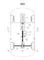
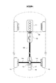
図1に示すように、車両の動力源となるエンジン11と、このエンジン11に接続された変速機12とが車両の前側部に搭載されている。変速機12は、機械式の変速機であり、複数の変速段の中から変速段を段階的に切り換える有段変速機であっても良いし、無段階に変速するCVT(無段変速機)であっても良い。これらのエンジン11及び変速機12は、エンジン11の出力軸(クランク軸)の軸方向が車両の前後方向となるように縦置きで配置されている。エンジン11の出力軸の動力が変速機12に伝達され、この変速機12の出力軸の動力がプロペラシャフト39やディファレンシャルギヤ機構13等を介して後輪15(車輪)の駆動軸14に伝達されるようになっている。
As shown in FIG. 1, an
更に、車両の動力源となる小径のモータジェネレータ(以下「MG」と表記する)16と、このMG16に接続された小径の減速機17とがエンジン11及び変速機12の後方に搭載されている。これらのMG16及び減速機17は、エンジン11が収容されたエンジンルームの外側(例えばエンジンルームと車室とを仕切るダッシュパネル18よりも後方)に配置されている。
Further, a small-diameter motor generator (hereinafter referred to as “MG”) 16 serving as a power source for the vehicle and a small-
また、MG16及び減速機17は、出力軸の軸方向が車両の前後方向となるように縦置きで配置され、変速機12の出力軸の動力が入力されるプロペラシャフト39の入力部に減速機17の出力軸が動力伝達機構20(例えばギヤやチェーン等)を介して連結されている。これにより、MG16の出力軸の動力が減速機17に伝達され、この減速機17の出力軸の動力がプロペラシャフト39やディファレンシャルギヤ機構13等を介して後輪15の駆動軸14に伝達されるようになっている。
The
図2に示すように、車両のフロアパネル21には、車両の前後方向に延びるフロアトンネル22が形成され、このフロアトンネル22に沿って変速機12及びプロペラシャフト39が配置されると共にMG16及び減速機17が配置されている。尚、図2では、MG16がフロアトンネル22の中央付近に配置された例が示されているが、これに限定されず、プロペラシャフト39等と干渉しないようにMG16及び減速機17を配置するようにすれば良い。また、フロアトンネル22内にMG16及び減速機17の少なくとも上部側(好ましくは全体)が収容されると共に、MG16及び減速機17の最下面がフロアパネル21及び排気管23等の組付部品(但し樹脂やゴム等の変形を前提とした部品を除く)を含む車両の最下面よりも上方に位置するように、MG16及び減速機17の外径が設定されている。
As shown in FIG. 2, a
以上のように構成されたハイブリッド車の駆動システムでは、走行モードを、例えば、エンジン走行モードとHV走行モードとEV走行モードとの間で切り換えるようになっている。エンジン走行モードは、エンジン11とMG16のうちエンジン11の動力のみで後輪15を駆動して車両を走行させるエンジン走行を行うモードである。HV走行モードは、エンジン11の動力とMG16の動力の両方で後輪15を駆動して車両を走行させるHV走行を行うモードである。EV走行モードは、エンジン11とMG16のうちMG16の動力のみで後輪15を駆動して車両を走行させるEV走行(MG16の動力のみで車両を発進させるEV発進を含む)を行うモードである。また、車両の減速時には、車両の運動エネルギをMG16で電気エネルギに変換してバッテリ33(図5参照)に充電(回収)する回生発電を行う。
In the hybrid vehicle drive system configured as described above, the travel mode is switched, for example, between an engine travel mode, an HV travel mode, and an EV travel mode. The engine travel mode is a mode in which the engine travels in which the vehicle travels by driving the
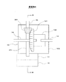
次に、図3及び図4に基づいてMG16の概略構成を説明する。
図3に示すように、MG16のケース24内には、回転軸25と一体的に回転する回転子26(ロータ)と、この回転子26の外周側に配置された固定子27(ステータ)とが設けられている。固定子27は、周方向に複数のスロット28(図4参照)を有する固定子コア29と、この固定子コア29に巻装された複数の相巻線よりなる固定子巻線30とを備えている。
Next, a schematic configuration of the
As shown in FIG. 3, in the
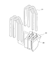
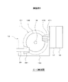
図4に示すように、固定子巻線30は、複数の略U字形状の導体セグメント31を所定のパターンでスロット28の一方側から挿入し、該スロット28の他方側から延出した導体セグメント31の先端部を所定のパターンで接合して形成されたセグメント型の巻線である。
As shown in FIG. 4, the stator winding 30 includes a plurality of substantially
また、図3に示すように、MG16のケース24内には、液状の冷媒32がMG16の外部と循環しないように封入されている。これにより、図3に矢印で示すように、MG16内部の熱を冷媒32を介してケース24に伝導させてMG16の外部に放出できるようにしている。また、図3に破線で示すように、MG16のケース24内には、MG16が停止した状態で少なくとも回転子26の外周部底面側が浸る位置(例えば回転軸25よりも少し低い位置)まで冷媒32が貯溜されている。これにより、MG16が回転したときに、回転子26の回転により冷媒32が掻き上げられて空気と混ざり合い、泡状の冷媒32がMG16のケース24内の隅々まで行き渡るようにしている。
Further, as shown in FIG. 3, a
冷媒32は、絶縁性を有する液体であり、例えばATF(自動変速機用の作動油)等の自動車用の潤滑油が用いられる。尚、一般に、自動車用の潤滑油は、十分な潤滑作用を発揮するために発泡を抑える消泡剤を添加することが多いが、本実施例では、潤滑油が空気と混ざり合う状態を利用するため、消泡剤を添加しないか又は望ましい発泡が起こる範囲内の添加量で消泡剤の添加量を調整しても良い。 The refrigerant 32 is an insulating liquid, and for example, lubricating oil for automobiles such as ATF (hydraulic oil for automatic transmission) is used. In general, a lubricating oil for automobiles is often added with an antifoaming agent that suppresses foaming in order to exert a sufficient lubricating action. However, in this embodiment, a state in which the lubricating oil is mixed with air is used. Therefore, the addition amount of the antifoaming agent may be adjusted with the addition amount within the range where the antifoaming agent is not added or desired foaming occurs.
次に、図5に基づいてMG16の駆動系の概略構成を説明する。
車両に搭載されたバッテリ33とMG16を駆動するインバータ35とが昇圧コンバータ34を介して接続され、MG16が昇圧コンバータ34及びインバータ35を介してバッテリ33と電力を授受するようになっている。バッテリ33は、二次電池等からなる直流電源である。昇圧コンバータ34は、バッテリ33の直流電圧を昇圧してインバータ35の入力電圧をバッテリ33の直流電圧よりも高くする。インバータ35は、昇圧コンバータ34によって昇圧された直流電圧を交流電圧に変換してMG16を駆動する。
Next, a schematic configuration of the drive system of the
A
これにより、バッテリ33の電圧よりも高い高電圧でMG16で駆動することができるため、車両の高速域(つまりMG16の高回転域)でのMG16の効率を向上させることができ、燃費を更に向上させることができる。また、バッテリ33の搭載量を必要最小限に抑えることができ、車両重量及びコストの増加を抑えることができる。
As a result, since the
また、本実施例1では、MG16の最大トルクTmax と、総合減速比GRtotal と、車両の重量IWと、車両の後輪15のタイヤ半径Rtyreとが、下記(1)式の関係を満たすように、MG16の最大トルクTmax と総合減速比GRtotal とが設定されている。ここで、総合減速比GRtotal は、減速機17の減速比と最終減速比(例えばディファレンシャルギヤ機構13での減速比)で決まる減速比である。
Tmax ×GRtotal >IW×1.05×Rtyre …(1)
In the first embodiment, the maximum torque Tmax of the
Tmax × GRtotal> IW × 1.05 × Rtyre (1)
上記(1)式は、MG16の動力のみで車両を発進させるEV発進を行う際の発進トルクを所定の下限トルクよりも大きくするための条件である。ここで、下限トルクは、燃費や排出ガスの測定用の走行パターンを規定する、JC08、NEDC、LA#4、US06、WLTPのうちで要求発進トルクが最も小さいNEDCにおける要求発進トルクに基づいて設定されている。従って、上記(1)式の関係を満たすようにMG16の最大トルクTmax と総合減速比GRtotal (減速機17の減速比)を設定することで、ハイブリッド車として実用的な加速度でEV発進を行うことができる。
The above equation (1) is a condition for making the starting torque larger than a predetermined lower limit torque when performing the EV starting to start the vehicle only with the power of the
更に、MG16の最大出力Pmax と、車両の重量IWとが、下記(2)式の関係を満たすように、MG16の最大出力Pmax が設定されている。
Pmax >|20.61×(−0.79)×IW| …(2)
Further, the maximum output Pmax of the
Pmax> | 20.61 × (−0.79) × IW | (2)
上記(2)式は、車両の減速時にMG16で回生発電を行う際の回生パワー(発電電力)を所定の下限パワーよりも大きくするための条件である。ここで、下限パワーは、JC08、NEDC、LA#4、US06、WLTPのうちで回生パワーが最も小さいJC08における回生パワーに基づいて設定されている。従って、上記(2)式の関係を満たすようにMG16の最大出力Pmax を設定することで、車両の減速時にMG16で回生発電を行う際の回生パワーをハイブリッド車として実用的なレベルにすることができる。
The above equation (2) is a condition for making the regenerative power (generated power) larger than the predetermined lower limit power when performing regenerative power generation with the
以上説明した本実施例1では、エンジン11及び変速機12が縦置きで配置された駆動システムにおいて、エンジン11が収容されたエンジンルームの外側にMG16及び減速機17を配置する。そして、変速機12の出力軸の動力が入力されるプロペラシャフト39に動力伝達機構20を介して減速機17の出力軸を連結するようにしている。
In the first embodiment described above, in the drive system in which the
これにより、MG16の動力を減速機17を介して後輪15の駆動軸14に伝達することができるため、小型のMG16でもEV走行に必要な軸トルク(駆動軸14のトルク)を発生させることができ、ハイブリッド車の重要な機能であるEV走行を実現することができる。これにより、MG16を小型化することが可能となり、更に、エンジンルームの外側にMG16及び減速機17を配置する構成とすることで、MG16及び減速機17の搭載スペースを容易に確保することができる。このため、エンジン11及び変速機12が縦置きで配置されたエンジン車(エンジンのみを動力源とする車両)をベースとしてハイブリッド車を製造する場合でも、ベースとなるエンジン車の車体構造をあまり変更せずに、EV走行を実現可能なハイブリッド車を製造することができる。
As a result, the power of the
また、MG16の駆動系(例えば、MG16、昇圧コンバータ34、インバータ35等)の故障が発生した場合でも、エンジン11の動力を変速機12を介して駆動軸14に伝達することができるため、エンジン11の動力で十分に自走(自力走行)することができる。更に、牽引等の負荷が高い条件においても、ベースとなるエンジン車と同等以上の駆動力を発揮することができる。また、MG16がエンジンルームの外側(つまり車体の中央寄り)に配置されるため、衝突事故等を起こした場合でも、MG16の損傷が低減されると共に、MG16が車外に露出することを防止して感電事故の可能性も低減することができる。
Further, even when a drive system of MG 16 (for example,
更に、本実施例1では、車両のフロアパネル21に形成されたフロアトンネル22内にMG16及び減速機17の少なくとも上部側が収容されると共にMG16及び減速機17の最下面が車両の最下面よりも上方に位置するようにMG16及び減速機17の外径を設定するようにしている。これにより、ベースとなるエンジン車の車体構造をほとんど変更することなく既存のフロアトンネル22を利用して、MG16及び減速機17を搭載することができる。また、MG16及び減速機17の最下面が車両の最下面よりも上方に位置するため、MG16及び減速機17と路面との接触を回避することができる。
Further, in the first embodiment, at least the upper sides of the
また、本実施例1では、MG16のケース24内に、液状の冷媒32をMG16の外部と循環しないように封入している。これにより、MG16内部の熱を冷媒32を介して効率的にケース24に伝導させてMG16の外部に放出することができ、MG16を効果的に冷却することができる。これにより、MG16の過熱を防止することができ、より高負荷、長時間のMG16の駆動が可能になる。また、MG16のケース24内で飛散・充満する冷媒32が固定子27や回転子26の冷却も促進するため、MG16のケース24内に複雑な流路を設けることなく、低コストで高い冷却効果を得ることができる。しかも、冷媒32をMG16の外部と循環させる循環路を設ける必要がなく、車両への搭載性を向上させることができる。また、MG16が高速回転する際に必要な軸受への潤滑油として冷媒32を供給することができるため、MG16の冷却効果を高めながらMG16の機械的寿命も延長することができる。更に、MG16の回転に伴う振動を減衰して静粛性を向上させることもできる。
In the first embodiment, the
更に、本実施例1では、MG16の固定子巻線30として、複数の略U字形状の導体セグメント31を所定のパターンで接合して形成されたセグメント型の巻線を用いるようにしている。これにより、固定子巻線30の巻線間(つまり導体セグメント31間)に適度な隙間が形成され、その隙間に冷媒32が容易に入り込むことにより、冷媒32を介した固定子巻線30とケース24との間の熱伝達効率を向上させることができる。
Further, in the first embodiment, as the stator winding 30 of the
また、本実施例1では、冷媒32として、絶縁性を有するものを用いるようにしている。これにより、MG16のケース24内の通電部品(例えば固定子巻線30等)の絶縁被膜に不具合が発生した場合や通電部品が損傷した場合でも、MG16のケース24内での冷媒32を介しての短絡を防止することができる。
In the first embodiment, an insulating material is used as the refrigerant 32. As a result, even when a failure occurs in the insulating coating of the energized parts (for example, the stator winding 30) in the
更に、本実施例1では、MG16のケース24内に、少なくとも回転子26の外周部底面側が浸る位置まで冷媒32を貯溜するようにしている。これにより、回転子26の回転により冷媒32が掻き上げられて空気と混ざり合い、回転する回転子26と冷媒32とが接触する際のせん断抵抗を低下させて、回転子26の回転抵抗を低下せることができ、MG16の効率を向上させることができる。また、空気と混ざり合った泡状の冷媒32がMG16のケース24内の隅々まで行き渡って、ケース24表面全体を伝熱や放熱のために最大限に利用することができると共に、冷媒32が固定子巻線30のコイルエンド部(固定子コア29の軸方向端面から突出する部分)、中性点、引き出し線36にも掛かることによって優れた冷却効果を得ることができる。
Further, in the first embodiment, the refrigerant 32 is stored in the
次に、図6を用いて本発明の実施例2を説明する。但し、前記実施例1と実質的に同一部分には同一符号を付して説明を省略又は簡略化し、主として前記実施例1と異なる部分について説明する。 Next, Embodiment 2 of the present invention will be described with reference to FIG. However, parts that are substantially the same as those in the first embodiment are denoted by the same reference numerals, and description thereof is omitted or simplified, and parts different from those in the first embodiment are mainly described.
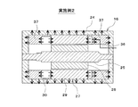
本実施例2では、図6に示すように、MG16のケース24内のうち固定子コア29の軸方向両側に、それぞれ放熱用の固体37が設けられている。この固体37は、少なくとも固定子巻線30のコイルエンド部(固定子コア29の軸方向端面から突出する部分)とケース24の内面(内周面及び軸方向内面)とに接触するように配置されている。これにより、図6に矢印で示すように、MG16の固定子巻線30のコイルエンド部の熱を固体37を介してケース24に伝導させてMG16の外部に放出できるようにしている。また、固体37は、絶縁性を有する樹脂等により略円筒状に形成され、MG16の回転部材である回転軸25及び回転子26には接触しないように配置されている。
In the second embodiment, as shown in FIG. 6, heat
以上説明した本実施例2では、MG16のケース24内に、少なくとも固定子巻線30のコイルエンド部とケース24の内面とに接触するように放熱用の固体27を配置するようにしている。これにより、MG16の固定子巻線30のコイルエンド部の熱を固体37を介して効率的にケース24に伝導させてMG16の外部に放出することができ、MG16を効果的に冷却することができる。これにより、MG16の過熱を防止することができ、より高負荷、長時間のMG16の駆動が可能になる。また、固定子巻線30のコイルエンド部を固体37で保持することができるため、コイルエンド部が励磁により振動して騒音が発生することを防止することができる。更に、エンジン11や車体の振動によりコイルエンド部やその絶縁被膜が損傷することを防止することができる。
In the second embodiment described above, the heat radiation solid 27 is arranged in the
更に、本実施例2では、MG16の固定子巻線30として、複数の略U字形状の導体セグメント31を所定のパターンで接合して形成されたセグメント型の巻線を用いるようにしている。これにより、固定子巻線30の巻線間(つまり導体セグメント31間)に適度な隙間が形成されるため、成形時、液体状態の固体37の材料がその隙間に容易に入り込むことにより固体37が隙間に充填され、固体37を介した固定子巻線30とケース24との間の熱伝達効率を向上させることができる。
Furthermore, in the second embodiment, as the stator winding 30 of the
また、本実施例2では、固体37として、絶縁性を有するものを用いるようにしている。これにより、コイルエンド部の絶縁被膜に不具合が発生した場合でも、MG16のケース内での固体37を介しての短絡を防止することができる。また、絶縁性の固体37の存在によりコイルエンド部とケース24との間の絶縁性が高められるため、コイルエンド部とケース24の距離(例えば軸方向の間隔)を縮めることができ、ケース24への放熱効果を高めることができると共に、MG16を小型化することができる。
In the second embodiment, as the solid 37, an insulating material is used. Thereby, even when a malfunction occurs in the insulating film of the coil end portion, it is possible to prevent a short circuit through the solid 37 in the case of the
更に、本実施例2では、固体37を、MG16の回転部材である回転軸25及び回転子26に接触しないように配置しているため、MG16の回転抵抗が増加することを防止することができる。
Furthermore, in the second embodiment, since the solid 37 is arranged so as not to contact the rotating
次に、図7を用いて本発明の実施例3を説明する。但し、前記実施例1と実質的に同一部分には同一符号を付して説明を省略又は簡略化し、主として前記実施例1と異なる部分について説明する。 Next, Embodiment 3 of the present invention will be described with reference to FIG. However, parts that are substantially the same as those in the first embodiment are denoted by the same reference numerals, and description thereof is omitted or simplified, and parts different from those in the first embodiment are mainly described.
本実施例3では、図7に示すように、減速機17の出力軸と動力伝達機構20との間に、動力伝達を断続するためのクラッチ38が設けられている。このクラッチ38は、油圧駆動式のプレート式クラッチであっても良いし、電磁駆動式の電磁クラッチであっても良いし、機械式のドッグクラッチ等でも良い。クラッチ38は、減速機17とは別体で設けられている(つまり減速機17のケース外に設けられている)。尚、減速機17と一体的にクラッチ38を設ける(つまり減速機17のケース内にクラッチ38を設ける)ようにしても良い。
In the third embodiment, as shown in FIG. 7, a clutch 38 for interrupting power transmission is provided between the output shaft of the
以上説明した本実施例3では、減速機17の出力軸と動力伝達機構20との間にクラッチ38を設けるようにしている。これにより、必要に応じてクラッチ38を切り離す(例えばエンジン走行モード時にクラッチ38を切り離す)ことで、MG16及び減速機17の連れ回しによるエネルギ損失(つまりMG16及び減速機17の回転負荷よるエネルギ損失)を無くすことができ、燃費を向上させることができる。また、MG16の故障時にクラッチ38を切り離すことで、エンジン11により自走を続けることができる。更に、減速機17やMG16の最高回転速度を車両の最高速度まで対応させる必要がなくなるため、より安価にシステムを構成することができる。
In the third embodiment described above, the clutch 38 is provided between the output shaft of the
次に、図8乃至図10を用いて本発明の実施例4を説明する。但し、前記実施例1と実質的に同一部分には同一符号を付して説明を省略又は簡略化し、主として前記実施例1と異なる部分について説明する。 Next, Embodiment 4 of the present invention will be described with reference to FIGS. However, parts that are substantially the same as those in the first embodiment are denoted by the same reference numerals, and description thereof is omitted or simplified, and parts different from those in the first embodiment are mainly described.
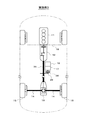
本実施例4では、図8に示すように、減速機17がディファレンシャルギヤ機構13の内部で、プロペラシャフト39の出力軸に直接連結されている。このときMG16及び減速機17の配置位置は、ディファレンシャルギヤ機構13よりも車両後方である。
In the fourth embodiment, as shown in FIG. 8, the
図9及び図10を用いて、プロペラシャフト39、ディファレンシャルギヤ機構13、減速機17の関係について詳細に説明する。
図9は、ディファレンシャルギヤ機構13を車両上方から見た図面である。図10は、図9のB−B断面を車両左側方向から見た図面である。
The relationship among the
FIG. 9 is a view of the
まず、プロペラシャフト39とディファレンシャルギヤ機構13との関係について説明する。
プロペラシャフト39の出力軸はベベルギア391に連結されている。そして、このベベルギア391は、ディファレンシャルギヤ機構13の構成要素であるリングギア131に噛み合っている。このリングギア131は駆動軸14と同軸上に配置された周知の構成である。
First, the relationship between the
The output shaft of the
また、リングギア131においてベベルギア391と噛み合う側の面とは反対側にディファレンシャルギヤ132が配置されている。このディファレンシャルギヤ132は、図示しない左右のサイドギアやピニオンギア等により構成された周知の構造であって、リングギア131に伝達した駆動力をドライブシャフト14に伝達することができる。
Further, a
次に、プロペラシャフト39、ディファレンシャルギヤ機構13と減速機17の計3者の関係について説明する。
ここで、プロペラシャフト39の出力側の端部に位置するベベルギア391は、減速機17の出力軸171に直接連結されている。つまりエンジン11によりプロペラシャフト39に伝達された動力は減速機17にも伝達され、また逆にMG16により減速機17に伝達された動力はプロペラシャフト39にも伝達される構造である。
Next, the relationship between the
Here, the
そして、MG16及び減速機17は、ディファレンシャルギヤ機構13のユニットケース133に固定されている。
ユニットケース133は、前述のリングギア131やディファレンシャルギヤ132を内部に収容している。また、ユニットケース133には、プロペラシャフト39やドライブシャフト14、減速機17の出力軸171が貫通する穴が設けられている。
また、図10に示すように、ドライブシャフト14は、減速機17の出力軸171よりも車両上方に配置されている。
The
The
Further, as shown in FIG. 10, the
以上説明した本実施例4では、減速機17がディファレンシャルギヤ機構13の内部でプロペラシャフト39の出力軸に直接連結されている。これにより前述の各実施例の様に動力伝達機構20を用いることなく、MG16で発生する駆動力を駆動軸14やプロペラシャフト39に伝達することができる。また、前述の各実施例の様に動力伝達機構20を用いることなく、駆動軸14やプロペラシャフト39からの動力をMG16に伝達することができる。つまりMG16により駆動力を発生させる場合には、MG16から後輪15に至る間の機械的損失を少なくすることができる。同様に、MG16により発電を行う場合には、後輪15からMG16に至る間の機械的損失を少なくすることができる。
In the fourth embodiment described above, the
また車両前方に比べて、比較的スペースの余裕がある車両後方にMG16や減速機17を配置することができる。
Further, the
次に、図11及び図12を用いて本発明の実施例5を説明する。但し、前記実施例1または実施例4と実質的に同一部分には同一符号を付して説明を省略又は簡略化し、主として前記実施例1または実施例4と異なる部分について説明する。 Next, Embodiment 5 of the present invention will be described with reference to FIGS. However, substantially the same parts as those in the first or fourth embodiment are denoted by the same reference numerals, and the description thereof will be omitted or simplified. The parts different from the first or fourth embodiment will be mainly described.
図11は、ディファレンシャルギヤ機構13を車両上方から見た鳥瞰図である。図12は、図11のC−C断面を車両左側方向から見た図面である。
本実施例5では、図11及び図12に示すように、減速機17がディファレンシャルギヤ機構13を介して、プロペラシャフト39の出力軸に連結されている。言い換えると、前述の実施例4の様にプロペラシャフト39と減速機17とが直接連結された構造ではなく、減速機17とプロペラシャフト39とが分断された構造である。
FIG. 11 is a bird's-eye view of the
In the fifth embodiment, as shown in FIGS. 11 and 12, the
プロペラシャフト39の出力軸はベベルギア391に連結されている。そして、このベベルギア391は、ディファレンシャルギヤ機構13の構成要素であるリングギア131に噛み合っている。
The output shaft of the
一方、減速機17の出力軸171は、前述のベベルギア391とは異なる第2ベベルギア172に連結されている。そしてこの第2ベベルギア172は、前述のベベルギア391とは異なる部位でリングギア131に噛み合っている。
On the other hand, the
このようにリングギア131は、プロペラシャフト39に連結されたベベルギア391と、MG16の減速機17に連結された第2ベベルギア172の両方のギアに噛み合っている。
Thus, the
更に、リングギア131においてベベルギア391と噛み合う面の側にディファレンシャルギヤ132が配置されている。
なお、MG16及び減速機17は、ディファレンシャルギヤ機構13のユニットケース13に固定されている点は前述の実施例4と同一である。
Further, a
The
また、ユニットケース133が、前述のリングギア131やディファレンシャルギヤ132を内部に収容している点、プロペラシャフト39やドライブシャフト14、減速機17の出力軸171が貫通する穴が設けられている点も前述の実施例4と同一である。
Further, the
ここで図12に示すように、プロペラシャフト39は、ドライブシャフト14及び減速機17の出力軸171よりも車両下方に配置されている。また、ドライブシャフト14は、減速機17の出力軸171よりも車両下方に配置されている。言い換えると、車両上方から減速機17の出力軸171、ドライブシャフト14、プロペラシャフト39の順番でこれらの構造物が配置されている。
Here, as shown in FIG. 12, the
以上説明した本実施例5では、前述の実施例4と同様にハイブリッド車の駆動システムの機械的損失を少なくすることができる。また、比較的スペースの余裕がある車両後方にMG16や減速機17を配置することができるという効果を奏することもできる。
In the fifth embodiment described above, the mechanical loss of the hybrid vehicle drive system can be reduced as in the fourth embodiment. Moreover, the effect that MG16 and the
更に、減速機17がディファレンシャルギヤ機構13を介して、プロペラシャフト39の出力軸に連結される構造にすることにより、MG16や減速機17を配置する際の自由度を向上することができる。
Furthermore, by adopting a structure in which the
図12においては、プロペラシャフト39の軸方向と、減速機17の出力軸171の軸方向とが平行である例を示したが、両者の軸方向の関係は平行である必要はなく、例えば30度や60度といった任意の角度に自由に配置することができる。また、減速機17やMG16の車両高さ方向の位置についても任意の高さに自由に配置することができる。
FIG. 12 shows an example in which the axial direction of the
尚、上記各実施例1〜5では、後輪駆動用の駆動システムに本発明を適用したが、これに限定されず、前輪駆動用の駆動システムに本発明を適用しても良い(例えば図1に示すシステムの前後を逆にしたシステムとしても良いし、エンジンと変速機の配置は図1のまま変速機の出力軸が前軸に接続される、いわゆる縦置きエンジン前輪駆動システムに適用しても良い)。 In the first to fifth embodiments, the present invention is applied to the drive system for driving the rear wheels. However, the present invention is not limited to this, and the present invention may be applied to the drive system for driving the front wheels (for example, FIG. The system shown in Fig. 1 may be reversed, and the arrangement of the engine and transmission may be applied to a so-called vertical engine front wheel drive system in which the output shaft of the transmission is connected to the front shaft while maintaining the arrangement of the engine and transmission. May be).
上記実施例4では、プロペラシャフト39の端部に位置するベベルギア391を、減速機17の出力軸171に連結する例を示した。しかし、この連結はリングギア131とは異なるギア等の部材を介して行われても良い。
In the fourth embodiment, an example in which the
上記実施例4では、減速機17の出力軸171を延伸させてプロペラシャフト39に接続する構成としたが、プロペラシャフト39の端部をベベルギア391よりも更に延伸させることで、減速機17の出力軸171に接続する構成としても良い。
In the fourth embodiment, the
ドライブシャフト14を減速機17の出力軸171よりも車両上方に配置する例を示した。しかしドライブシャフト14を、減速機17の出力軸171よりも車両下方に配置しても良い。
The example which has arrange | positioned the
上記実施例4及び実施例5では、減速機17の出力軸がクラッチを介することなくディファレンシャルギヤ機構13に連結されていた。しかし、減速機17の出力軸171とディファレンシャルギヤ機構13との間にクラッチを配置しても良い。
In the said Example 4 and Example 5, the output shaft of the
上記実施例4及び実施例5では、MG16及び減速機17は、ディファレンシャルギヤ機構13のユニットケース133と一体に形成されても良いし、MG16及び減速機17をユニットケース133の中に配置しても良い。
In the fourth embodiment and the fifth embodiment, the
11…エンジン、12…変速機、14…駆動軸、15…後輪、16…MG、17…減速機
DESCRIPTION OF
Claims (13)
前記車両の動力源となるモータジェネレータ(以下「MG」と表記する)(16)と、該MGに接続された減速機(17)とを備え、
前記エンジンが収容されたエンジンルームの外側に前記MG及び前記減速機が配置され、前記変速機の出力軸の動力を車輪(15)の駆動軸(14)に伝達する動力伝達系に前記減速機の出力軸が動力伝達可能に連結されていることを特徴とする車両の駆動装置。 An engine (11) serving as a power source for the vehicle, and a transmission (12) connected to the engine, the engine and the speed change so that the axial direction of the output shaft of the engine is the front-rear direction of the vehicle In the vehicle drive device in which the machine is arranged vertically,
A motor generator (hereinafter referred to as “MG”) (16) as a power source of the vehicle, and a speed reducer (17) connected to the MG;
The MG and the speed reducer are arranged outside an engine room in which the engine is accommodated, and the speed reducer is connected to a power transmission system that transmits power of an output shaft of the transmission to a drive shaft (14) of a wheel (15). An output shaft of the vehicle is connected so that power can be transmitted.
Tmax ×GRtotal >IW×1.05×Rtyre…(1)
Pmax >|20.61×(−0.79)×IW|…(2) The maximum torque Tmax of the MG, the maximum output Pmax of the MG, the overall reduction ratio GRtotal determined by the reduction ratio and the final reduction ratio of the reduction gear, the weight IW of the vehicle, and the tire radius Rtyre of the vehicle, 11. The maximum torque Tmax, the maximum output Pmax, and the total reduction ratio GRtotal are set so as to satisfy the relationship of the following formula (1) and the following formula (2). The drive device of the vehicle in any one.
Tmax × GRtotal> IW × 1.05 × Rtyre (1)
Pmax> | 20.61 × (−0.79) × IW | (2)
Priority Applications (4)
| Application Number | Priority Date | Filing Date | Title |
|---|---|---|---|
| DE112016003612.4T DE112016003612T5 (en) | 2015-08-07 | 2016-07-22 | Device for driving a vehicle |
| US15/748,592 US20190001802A1 (en) | 2015-08-07 | 2016-07-22 | Device for driving vehicle |
| PCT/JP2016/071496 WO2017026242A1 (en) | 2015-08-07 | 2016-07-22 | Device for driving vehicle |
| CN201680045597.9A CN107921857A (en) | 2015-08-07 | 2016-07-22 | Automotive proplsion |
Applications Claiming Priority (2)
| Application Number | Priority Date | Filing Date | Title |
|---|---|---|---|
| JP2015156831 | 2015-08-07 | ||
| JP2015156831 | 2015-08-07 |
Publications (2)
| Publication Number | Publication Date |
|---|---|
| JP2017036026A true JP2017036026A (en) | 2017-02-16 |
| JP2017036026A5 JP2017036026A5 (en) | 2017-11-16 |
Family
ID=58047148
Family Applications (1)
| Application Number | Title | Priority Date | Filing Date |
|---|---|---|---|
| JP2016021262A Pending JP2017036026A (en) | 2015-08-07 | 2016-02-05 | Driving apparatus of vehicle |
Country Status (4)
| Country | Link |
|---|---|
| US (1) | US20190001802A1 (en) |
| JP (1) | JP2017036026A (en) |
| CN (1) | CN107921857A (en) |
| DE (1) | DE112016003612T5 (en) |
Cited By (3)
| Publication number | Priority date | Publication date | Assignee | Title |
|---|---|---|---|---|
| JPWO2018190124A1 (en) * | 2017-04-13 | 2020-02-27 | パナソニックIpマネジメント株式会社 | Coil and motor using the same |
| WO2023167195A1 (en) * | 2022-03-02 | 2023-09-07 | ニデック株式会社 | Motor, and electric vehicle |
| KR102619367B1 (en) * | 2023-05-26 | 2023-12-29 | 윤주성 | Hybrid vehicle |
Families Citing this family (3)
| Publication number | Priority date | Publication date | Assignee | Title |
|---|---|---|---|---|
| CN106537733A (en) * | 2014-07-25 | 2017-03-22 | 三菱电机株式会社 | Rotating electric machine |
| CN111546881A (en) * | 2020-05-26 | 2020-08-18 | 湖南行必达网联科技有限公司 | Vehicle power generation system and power generation control method |
| JP7447872B2 (en) * | 2021-06-21 | 2024-03-12 | トヨタ自動車株式会社 | power equipment |
Citations (16)
| Publication number | Priority date | Publication date | Assignee | Title |
|---|---|---|---|---|
| JPH0995149A (en) * | 1995-09-29 | 1997-04-08 | Fuji Heavy Ind Ltd | Driving device of hybrid car |
| JPH1199838A (en) * | 1997-09-30 | 1999-04-13 | Fuji Heavy Ind Ltd | Driving device for hybrid powered automobile |
| JP2001173762A (en) * | 1999-10-05 | 2001-06-26 | Aisin Aw Co Ltd | Lubrication device for drive unit |
| JP2002125337A (en) * | 2000-10-17 | 2002-04-26 | Mitsubishi Electric Corp | Alternator for vehicle |
| JP2004048939A (en) * | 2002-07-12 | 2004-02-12 | Denso Corp | Coil end contact cooling rotating electric machine |
| JP2004357432A (en) * | 2003-05-29 | 2004-12-16 | Toyota Motor Corp | Motor unit and vehicle equipped therewith |
| JP2005028968A (en) * | 2003-07-10 | 2005-02-03 | Fuji Heavy Ind Ltd | Traveling device for vehicle |
| JP2005145334A (en) * | 2003-11-18 | 2005-06-09 | Fuji Heavy Ind Ltd | Driving force controlling device for hybrid vehicle |
| US20060030450A1 (en) * | 2004-08-09 | 2006-02-09 | Kyle Ronald L | Hybrid vehicle formed by converting a conventional IC engine powered vehicle and method of such conversion |
| JP2006123896A (en) * | 2004-10-29 | 2006-05-18 | American Axle & Manufacturing Inc | Axle assembly for motor vehicle, and car propulsion method |
| JP2008168783A (en) * | 2007-01-11 | 2008-07-24 | Hitachi Ltd | Vehicle drive |
| JP2008306861A (en) * | 2007-06-08 | 2008-12-18 | Komatsu Ltd | Machine utilizing motor |
| JP2011037296A (en) * | 2009-08-06 | 2011-02-24 | Mazda Motor Corp | Method for constituting vehicular driving device |
| US20130075183A1 (en) * | 2011-09-23 | 2013-03-28 | Yoshitaka KOCHIDOMARI | Vehicle With Electric Transaxle |
| JP2015196413A (en) * | 2014-03-31 | 2015-11-09 | スズキ株式会社 | hybrid four-wheel-drive vehicle |
| JP2017030594A (en) * | 2015-08-03 | 2017-02-09 | いすゞ自動車株式会社 | Hybrid vehicle and control method for the same |
Family Cites Families (13)
| Publication number | Priority date | Publication date | Assignee | Title |
|---|---|---|---|---|
| US6554088B2 (en) * | 1998-09-14 | 2003-04-29 | Paice Corporation | Hybrid vehicles |
| JP2005306137A (en) * | 2004-04-20 | 2005-11-04 | Tochigi Fuji Ind Co Ltd | Hybrid vehicle |
| US20100044129A1 (en) * | 2004-08-09 | 2010-02-25 | Hybrid Electric Conversion Co., Llc | Hybrid vehicle formed by converting a conventional ic engine powered vehicle and method of such conversion |
| US7780562B2 (en) * | 2006-01-09 | 2010-08-24 | General Electric Company | Hybrid vehicle and method of assembling same |
| JP4572907B2 (en) * | 2007-03-29 | 2010-11-04 | トヨタ自動車株式会社 | Motor control device, control method, and control program |
| DE112012004494T5 (en) * | 2011-10-27 | 2014-07-17 | Toyota Jidosha Kabushiki Kaisha | Segment coil, method for producing the segment coil and stator with the segment coil |
| JP5483293B2 (en) * | 2011-11-29 | 2014-05-07 | 富士重工業株式会社 | Hybrid vehicle body structure |
| JP5737273B2 (en) * | 2012-11-15 | 2015-06-17 | 株式会社デンソー | Stator winding and method for manufacturing stator winding |
| JP5896250B2 (en) * | 2013-09-18 | 2016-03-30 | 株式会社デンソー | Rotating electric machine stator |
| DE102013019901A1 (en) * | 2013-11-28 | 2015-05-28 | Audi Ag | Drive device for a hybrid-powered motor vehicle |
| JP6370058B2 (en) | 2014-02-24 | 2018-08-08 | 株式会社ナガセビューティケァ | Method for producing rubusoside |
| JP6137552B2 (en) * | 2014-07-08 | 2017-05-31 | 株式会社デンソー | Rotating electric machine |
| JP6044691B2 (en) | 2015-10-01 | 2016-12-14 | 国立研究開発法人情報通信研究機構 | Logic inference system, calculation learning device, and logic inference method |
-
2016
- 2016-02-05 JP JP2016021262A patent/JP2017036026A/en active Pending
- 2016-07-22 DE DE112016003612.4T patent/DE112016003612T5/en not_active Ceased
- 2016-07-22 CN CN201680045597.9A patent/CN107921857A/en active Pending
- 2016-07-22 US US15/748,592 patent/US20190001802A1/en not_active Abandoned
Patent Citations (16)
| Publication number | Priority date | Publication date | Assignee | Title |
|---|---|---|---|---|
| JPH0995149A (en) * | 1995-09-29 | 1997-04-08 | Fuji Heavy Ind Ltd | Driving device of hybrid car |
| JPH1199838A (en) * | 1997-09-30 | 1999-04-13 | Fuji Heavy Ind Ltd | Driving device for hybrid powered automobile |
| JP2001173762A (en) * | 1999-10-05 | 2001-06-26 | Aisin Aw Co Ltd | Lubrication device for drive unit |
| JP2002125337A (en) * | 2000-10-17 | 2002-04-26 | Mitsubishi Electric Corp | Alternator for vehicle |
| JP2004048939A (en) * | 2002-07-12 | 2004-02-12 | Denso Corp | Coil end contact cooling rotating electric machine |
| JP2004357432A (en) * | 2003-05-29 | 2004-12-16 | Toyota Motor Corp | Motor unit and vehicle equipped therewith |
| JP2005028968A (en) * | 2003-07-10 | 2005-02-03 | Fuji Heavy Ind Ltd | Traveling device for vehicle |
| JP2005145334A (en) * | 2003-11-18 | 2005-06-09 | Fuji Heavy Ind Ltd | Driving force controlling device for hybrid vehicle |
| US20060030450A1 (en) * | 2004-08-09 | 2006-02-09 | Kyle Ronald L | Hybrid vehicle formed by converting a conventional IC engine powered vehicle and method of such conversion |
| JP2006123896A (en) * | 2004-10-29 | 2006-05-18 | American Axle & Manufacturing Inc | Axle assembly for motor vehicle, and car propulsion method |
| JP2008168783A (en) * | 2007-01-11 | 2008-07-24 | Hitachi Ltd | Vehicle drive |
| JP2008306861A (en) * | 2007-06-08 | 2008-12-18 | Komatsu Ltd | Machine utilizing motor |
| JP2011037296A (en) * | 2009-08-06 | 2011-02-24 | Mazda Motor Corp | Method for constituting vehicular driving device |
| US20130075183A1 (en) * | 2011-09-23 | 2013-03-28 | Yoshitaka KOCHIDOMARI | Vehicle With Electric Transaxle |
| JP2015196413A (en) * | 2014-03-31 | 2015-11-09 | スズキ株式会社 | hybrid four-wheel-drive vehicle |
| JP2017030594A (en) * | 2015-08-03 | 2017-02-09 | いすゞ自動車株式会社 | Hybrid vehicle and control method for the same |
Cited By (4)
| Publication number | Priority date | Publication date | Assignee | Title |
|---|---|---|---|---|
| JPWO2018190124A1 (en) * | 2017-04-13 | 2020-02-27 | パナソニックIpマネジメント株式会社 | Coil and motor using the same |
| US11489387B2 (en) | 2017-04-13 | 2022-11-01 | Panasonic Intellectual Property Management Co., Ltd. | Coil and motor using same |
| WO2023167195A1 (en) * | 2022-03-02 | 2023-09-07 | ニデック株式会社 | Motor, and electric vehicle |
| KR102619367B1 (en) * | 2023-05-26 | 2023-12-29 | 윤주성 | Hybrid vehicle |
Also Published As
| Publication number | Publication date |
|---|---|
| CN107921857A (en) | 2018-04-17 |
| US20190001802A1 (en) | 2019-01-03 |
| DE112016003612T5 (en) | 2018-05-03 |
Similar Documents
| Publication | Publication Date | Title |
|---|---|---|
| JP2017036026A (en) | Driving apparatus of vehicle | |
| JP3536837B2 (en) | Drive unit for hybrid vehicle | |
| JP4218671B2 (en) | Hybrid vehicle power output device | |
| JP2008072813A (en) | Drive unit for vehicle | |
| KR20060087412A (en) | Hybrid vehicle | |
| JP2009262857A (en) | Driving device | |
| JP2012096738A (en) | Cooling system | |
| JP7103165B2 (en) | Electric vehicle | |
| JP2007161111A (en) | Running gear of vehicle | |
| JP4968543B2 (en) | Drive device | |
| JP2008256075A (en) | Power transmission device | |
| JP6662359B2 (en) | Driving force control device for hybrid vehicle | |
| JP6390547B2 (en) | Vehicle drive device | |
| JP2011093458A (en) | Vehicle structure of hybrid vehicle | |
| JP2009241910A (en) | Cooling structure of in-wheel motor | |
| US10843576B2 (en) | Electric vehicle | |
| WO2019202945A1 (en) | Motor unit | |
| WO2017026242A1 (en) | Device for driving vehicle | |
| JP6693604B2 (en) | Power transmission device for four-wheel drive vehicle | |
| JP2006264463A (en) | Drive of hybrid vehicle | |
| US20230039195A1 (en) | Motor unit and electric car | |
| JP2023049661A (en) | Electrically-driven power unit | |
| JP2009261072A (en) | Motor for vehicle | |
| JP2015008595A (en) | Machinery and electricity integrated drive apparatus for electrically-driven vehicle | |
| KR20140071580A (en) | Electric Vehicle |
Legal Events
| Date | Code | Title | Description |
|---|---|---|---|
| RD04 | Notification of resignation of power of attorney |
Free format text: JAPANESE INTERMEDIATE CODE: A7424 Effective date: 20160307 |
|
| RD03 | Notification of appointment of power of attorney |
Free format text: JAPANESE INTERMEDIATE CODE: A7423 Effective date: 20160309 |
|
| A521 | Request for written amendment filed |
Free format text: JAPANESE INTERMEDIATE CODE: A523 Effective date: 20171006 |
|
| A621 | Written request for application examination |
Free format text: JAPANESE INTERMEDIATE CODE: A621 Effective date: 20171006 |
|
| A131 | Notification of reasons for refusal |
Free format text: JAPANESE INTERMEDIATE CODE: A131 Effective date: 20180828 |
|
| A521 | Request for written amendment filed |
Free format text: JAPANESE INTERMEDIATE CODE: A523 Effective date: 20181009 |
|
| A131 | Notification of reasons for refusal |
Free format text: JAPANESE INTERMEDIATE CODE: A131 Effective date: 20190205 |
|
| A521 | Request for written amendment filed |
Free format text: JAPANESE INTERMEDIATE CODE: A523 Effective date: 20190328 |
|
| A131 | Notification of reasons for refusal |
Free format text: JAPANESE INTERMEDIATE CODE: A131 Effective date: 20190910 |
|
| A02 | Decision of refusal |
Free format text: JAPANESE INTERMEDIATE CODE: A02 Effective date: 20200331 |