EP1938986B1 - Procédé pour stocker et pour décharger un revêtement d'un cylindre d'une presse - Google Patents
Procédé pour stocker et pour décharger un revêtement d'un cylindre d'une presse Download PDFInfo
- Publication number
- EP1938986B1 EP1938986B1 EP08150722A EP08150722A EP1938986B1 EP 1938986 B1 EP1938986 B1 EP 1938986B1 EP 08150722 A EP08150722 A EP 08150722A EP 08150722 A EP08150722 A EP 08150722A EP 1938986 B1 EP1938986 B1 EP 1938986B1
- Authority
- EP
- European Patent Office
- Prior art keywords
- printing
- cylinder
- forme
- forme cylinder
- packing
- Prior art date
- Legal status (The legal status is an assumption and is not a legal conclusion. Google has not performed a legal analysis and makes no representation as to the accuracy of the status listed.)
- Expired - Lifetime
Links
- 238000007639 printing Methods 0.000 title claims description 471
- 238000000034 method Methods 0.000 title claims description 37
- 238000003860 storage Methods 0.000 claims abstract description 69
- 238000012856 packing Methods 0.000 claims 23
- 239000000725 suspension Substances 0.000 description 85
- 238000004519 manufacturing process Methods 0.000 description 32
- 238000003825 pressing Methods 0.000 description 16
- 238000005096 rolling process Methods 0.000 description 12
- 239000000463 material Substances 0.000 description 10
- 238000005452 bending Methods 0.000 description 7
- 230000005484 gravity Effects 0.000 description 7
- 230000000284 resting effect Effects 0.000 description 7
- 238000007599 discharging Methods 0.000 description 5
- 238000010276 construction Methods 0.000 description 4
- 238000013461 design Methods 0.000 description 4
- 230000006870 function Effects 0.000 description 4
- 230000001154 acute effect Effects 0.000 description 3
- 238000006073 displacement reaction Methods 0.000 description 2
- 229910052751 metal Inorganic materials 0.000 description 2
- 239000002184 metal Substances 0.000 description 2
- 238000005192 partition Methods 0.000 description 2
- 230000008093 supporting effect Effects 0.000 description 2
- 238000012546 transfer Methods 0.000 description 2
- 238000004804 winding Methods 0.000 description 2
- 229910000838 Al alloy Inorganic materials 0.000 description 1
- 230000000712 assembly Effects 0.000 description 1
- 238000000429 assembly Methods 0.000 description 1
- 238000001514 detection method Methods 0.000 description 1
- 230000001939 inductive effect Effects 0.000 description 1
- 239000000976 ink Substances 0.000 description 1
- 238000009434 installation Methods 0.000 description 1
- 238000012423 maintenance Methods 0.000 description 1
- 230000007257 malfunction Effects 0.000 description 1
- 239000007769 metal material Substances 0.000 description 1
- 238000007645 offset printing Methods 0.000 description 1
- 230000001737 promoting effect Effects 0.000 description 1
- 238000004080 punching Methods 0.000 description 1
- 230000003134 recirculating effect Effects 0.000 description 1
- 230000002441 reversible effect Effects 0.000 description 1
- 230000003319 supportive effect Effects 0.000 description 1
- 238000012360 testing method Methods 0.000 description 1
- 230000001960 triggered effect Effects 0.000 description 1
Images


Classifications
-
- B—PERFORMING OPERATIONS; TRANSPORTING
- B41—PRINTING; LINING MACHINES; TYPEWRITERS; STAMPS
- B41F—PRINTING MACHINES OR PRESSES
- B41F30/00—Devices for attaching coverings or make-ready devices; Guiding devices for coverings
- B41F30/04—Devices for attaching coverings or make-ready devices; Guiding devices for coverings attaching to transfer cylinders
-
- B—PERFORMING OPERATIONS; TRANSPORTING
- B41—PRINTING; LINING MACHINES; TYPEWRITERS; STAMPS
- B41F—PRINTING MACHINES OR PRESSES
- B41F27/00—Devices for attaching printing elements or formes to supports
- B41F27/12—Devices for attaching printing elements or formes to supports for attaching flexible printing formes
- B41F27/1206—Feeding to or removing from the forme cylinder
-
- B—PERFORMING OPERATIONS; TRANSPORTING
- B41—PRINTING; LINING MACHINES; TYPEWRITERS; STAMPS
- B41P—INDEXING SCHEME RELATING TO PRINTING, LINING MACHINES, TYPEWRITERS, AND TO STAMPS
- B41P2227/00—Mounting or handling printing plates; Forming printing surfaces in situ
- B41P2227/60—Devices for transferring printing plates
- B41P2227/63—Devices for removing printing plates
Definitions
- the invention relates to a method for storing an elevator to be paid off from a cylinder of a printing machine with a leading end and a trailing end according to the preamble of claim 1.
- DE 199 41 634 A1 is a method for supplying and discharging flexible printing plates to or from a printing forme cylinder of a printing machine known, wherein the printing forme cylinder discharged printing forms are stored in an attached to the printing forme cylinder receiving box.
- a transport system for transporting printing forms wherein the printing plates are transported vertically suspended on a means of transport to a particular forme cylinder of a printing machine having a plurality of cylinders, wherein in the vicinity of each forme cylinder an annular storage system is provided, in which transported to the forme cylinder Recirculating printing forms hanging vertically.
- a printing forme to be supplied to the forme cylinder can be removed or a printing form removed from the forme cylinder can be transferred to the storage system.
- the occupancy of the forme cylinder with a new printing form or the removal of a no longer required printing form from the forme cylinder by an operator or by means of a plate handling system, for. B. a robot.
- a method and apparatus for automatically feeding a printing plate to a plate cylinder or for discharging a plate cylinder of a rotary printing machine are known.
- the method of automatically feeding a printing plate to a plate cylinder of a rotary printing press, the plate cylinder including means for clamping and clamping the printing plate provides that the printing plate is placed in a storage chamber of a printing plate feeding device that rotates the plate cylinder to a printing plate feeding position and the printing plate is fed by means of a number of transport rollers of a clamping device of the plate cylinder.
- the method of automatically discharging a printing plate from a plate cylinder of a rotary printing press, the plate cylinder including means for releasing and releasing the printing plate is characterized in that the plate cylinder rotates forward to a printing plate release position that a clamping flap for detecting a printing plate end is opened the plate cylinder is rotated backwards so that a clamping flap for detecting a printing plate beginning opened and that the printing plate is fed by means of a number of transport rollers of a storage chamber of Druckplattenzulite- or -ab conveyvorraum.
- the device for carrying out the aforementioned method has at least one transport roller designed as a drive roller and a transport roller designed as a pressure roller, wherein the pressure roller can be adjusted to the drive roller.
- a pivotally mounted pressure roller for pressing the pressure plate to the plate cylinder and ejection fingers may be provided, wherein the ejection fingers may have tips which are pivotally mounted in the periphery of the plate cylinder.
- the storage chamber of Druckplattenzulite- or - be discharged pivoting about a hinge.
- the DE 39 40 796 A1 describes a device for automatically changing a printing plate on a plate cylinder of a rotary printing press, wherein the plate cylinder, inter alia, means for clamping and clamping the printing plate, wherein the printing plate changing device has two storage chambers, so that an am Plate cylinder dissolved pressure plate can be guided by means of transport rollers in the one storage chamber, while a stored in the other storage chamber pressure plate is fed by means of transport rollers of a clamping device of the plate cylinder.
- the EP 1 084 839 A1 describes a device for holding and conveying a printing forme.
- the device has translational conveying devices which convey a printing forme to be mounted on a forme cylinder or a printing forme to be removed from a forme cylinder. While the device is tilted from a rest position to its operating position for changing a printing form about an axis of rotation, a hook pivots only due to its own weight in the space in which the printing plate is mounted and secures the printing forme at its trailing beveled end against accidental falling out this room.
- WO 93/04863 A1 a device for automatically changing printing plates is known, wherein a plurality of printing plates are stored in a magazine and wherein an exchange of a printing plate with a forme cylinder takes place only under an inclination of the magazine.
- the invention has for its object to provide a method for storing a derived from a cylinder of a printing machine elevator with a leading end and a trailing end.
- the advantage achievable with the invention is, in particular, that several lifts on a cylinder can be changed quickly and reliably at the same time or at least in a very rapid sequence on a cylinder.
- the elevator falls due to the operation of a holding member from a vertically upper storage position to an underlying storage position, from which it can be transported to the cylinder.
- the actuation of the holding element of the stored elevator changes in free fall from its vertical upper storage position in the underlying storage position.
- the actuation of the holding element is preferably carried out with a controllable drive and can thus be made by machine.
- the device is also suitable for in particular in their length flexurally elastic lifts with folded at their ends EinHonbringeln. Moreover, the device builds extremely flat in their height so that they do not hinder the required accessibility to the printing unit.
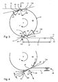
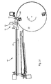
- An elevator 01 ( Fig. 1 ), the z. B. is configured as a plate-shaped printing plate 01 or as a support plate carrying a blanket, has a substantially rectangular surface with a length L and a width B, wherein the length L z. B. measured values between 400 mm and 1300 mm and the width B z. B. may have measured values between 280 mm and 1500 mm. Preferred measured values are for the length L z. B. between 360 mm and 600 mm and for the width B z. B. between 250 mm and 430 mm.
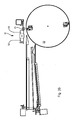
- the surface has a support side, which is referred to below support surface 02, with which the elevator 01 rests in the arranged on a lateral surface 07 of a cylinder 06 state ( Fig. 2 ).
- the back of the support surface 02 is a work surface which, in the case where the elevator 01 is formed as a printing forme 01, is provided with a printed image or at least can be provided with a printed image.
- the elevator 01 has two opposite ends 03; 04 preferably each with angled Einhotbringeln 13; 14, wherein the ends 03; 04 limit the bearing surface 02 and wherein the suspension legs 13; 14 each preferably extend entirely or at least partially across the width B of the elevator 01.
- the bearing surface 02 of the elevator 01 is flexible at least along the length L and in an arrangement of the elevator 01 on the lateral surface 07 of the cylinder 06 whose curvature can be adapted ( Fig. 2 ).
- the length L of the bearing surface 02 thus extends in the direction of the circumference of the cylinder 06, whereas the width B of the bearing surface 02 extends in the axial direction of the cylinder 06.
- the suspension legs 13; 14 of the elevator 01 fixed by means of a holding device, wherein the holding device is arranged in a channel 08, wherein the channel 08 usually extends in the axial direction to the cylinder 06.
- a rectified with the production direction P of the cylinder 06 end 03 of the elevator 01 is referred to as the leading end 03, whereas the opposite end 04 is the trailing end 04 of the elevator 01.
- At least the ends 03; 04 of the elevator 01 with the suspension legs 13 formed thereon; 14 consist of a rigid, z. B. metallic material, eg. B. of an aluminum alloy.
- the material thickness D of the elevator 01 Fig.
- the elevator 01 as a whole or at least at its ends 03; 04 made of a dimensionally stable material, so that the ends 03; 04 are permanently deformable by a bend against a material-specific resistance.
- At least at one end 03; 04 of the elevator 01 ( Fig. 1 ), but preferably at both ends 03; 04 are along a bending edge 11; 12 each a folded suspension leg 13; 14 formed, wherein the suspension legs 13; 14 in a narrow, in particular slot-shaped opening 09 of the channel 08 of the cylinder 06 ( Fig. 2 ) insertable and there by means of a holding device, for. B. a clamping device can be fastened.
- a clamping device can be fastened.
- the opening angle ⁇ 1; ⁇ 1 usually lie between 30 ° and 140 °. If the opening angle ⁇ 1 is assigned to the leading end 03 of the elevator 01, it is preferably executed at an acute angle, in particular it is 45 °.
- the opening angle ⁇ 1 at the trailing end 04 of the elevator 01 is often preferably greater than 80 ° or obtuse-angled, in particular it is 85 ° or 135 °.
- the folded suspension leg 13 at the leading end 03 has a length L13, which z. B. in the range of 4 mm to 30 mm, in particular between 4 mm and 15 mm. Of the folded Ein fatigueschenkei 14 at the trailing end 04 has a length l14, the z. B. 4 mm to 30 mm, in particular between 8 mm and 12 mm, with the shorter length measure is preferred to simplify removal of the suspension legs 13 as possible; 14 to ensure from the opening 09 of the channel 08.
- the Fig. 2 shows in a simplified sectional view of a cylinder 06 with a lateral surface 07 and a channel 08, which has a narrow, slot-shaped opening 09 with a slot width S to the lateral surface 07, wherein the slot width S is less than 5 mm and preferably in the range of 1 mm 3 mm.
- the opening 09 has a front edge 16 and a rear edge 17 in the production direction P of the cylinder 06. Between the extending from the front edge 16 to the channel 08 toward wall 18 and an imaginary, resting on the lateral surface 07 of the cylinder 06 on the opening 09 tangent T09 an acute opening angle ⁇ 2 is formed, which is between 30 ° and 50 °, preferably 45 ° is.
- the bent suspension leg 13 at the leading end 03 of the elevator 01 is thus preferably positively connected to this front edge 16 of the opening 09, because the opening angle ⁇ 1 at the leading end 03 of the elevator 01 is preferably adapted to the opening angle ⁇ 2. In the same way it behaves at the trailing end 04 of the elevator 01.
- an opening angle ⁇ 2 which is either between 80 ° and 95 °, preferably 90 °, or between 120 ° and 150 °, preferably 135 °.
- the bent suspension leg 14 at the trailing end 04 of the elevator 01 is thus preferably positively clamped at this rear edge 17 of the opening 09, because the opening angle ⁇ 1 at the trailing end 04 of the elevator 01 is at least approximately adapted to the opening angle ⁇ 2.
- z. B. at least one preferably pivotally mounted holding means 21 and a preferably biased spring element 22 is arranged, wherein the Spring element 22, the holding means 21 z. B. against the folded suspension leg 14 at the trailing end 04 presses, which is hooked to the opening 09 at its rear edge 17, whereby the suspension leg 14 at the trailing end 04 at the extending from the rear edge 17 to the channel 08 extending wall 19 becomes.
- a setting means 23 preferably a pneumatically actuable adjusting means 23 is provided, which pivots the holding means 21 against the force of the spring element 22 during its actuation.
- the holding device described by way of example consists essentially of the holding means 21, the spring element 22 and the adjusting means 23.
- the exemplified cylinder 06 is preferably such that on its lateral surface 07 a plurality of, preferably similar elevators 01 can be arranged. If the cylinder 06 is designed as a forme cylinder, it can in its axial direction side by side z. B. with up to six plate-shaped printing plates 01 are occupied. It is also preferably provided that more than one elevator 01 can be arranged on the cylinder 06 in the direction of its circumference. Thus, in the cylinder 06 under the lateral surface 07 z. B. two axially extending to the cylinder 06 channels 08 may be provided, which have for attachment of elevators 01 axially to the cylinder 06 extending openings 09, wherein the openings 09 at the periphery of the cylinder 06 z. B.
- a method for mounting a flexible elevator 01 on a cylinder 06 of a printing machine is described by way of example, wherein two elevators 01 can be arranged on the cylinder 06 along its circumference one behind the other and wherein each elevator 01 has a leading end relative to the production direction P of the cylinder 06 03 and a trailing end 04 ( Fig. 3 ).
- a suspension leg 13 is formed, said suspension leg 13 is bent to the extended length L of the elevator 01 with an opening angle ⁇ 1 of a maximum of 90 °, preferably 45 °.
- At least one preferably slot-shaped opening 09 are provided with a first edge 16 in the production direction P of the cylinder 06 and a second edge 17, wherein the edges 16; 17 in the axial direction of the cylinder 06 preferably parallel to each other.
- the leading end 03 of the elevator 01 is z. B.
- the leading end 03 of the elevator 01 can be elastically pretensioned ( Fig. 4 ), so that formed on the leading end 03 suspension leg 13 as a result of a directed on the cylinder 06 return torque MR springs into the opening 09, as soon as the opening 09 of the cylinder 06 and the contact line 27 of Einkowels 13 with the lateral surface 07 of the cylinder 06 due to a relative movement between the elevator 01 and the cylinder 06 directly opposite each other, wherein the relative movement takes place in particular by the rotation of the cylinder 06 in the direction of production P.
- the return torque MR results from the fact that the elevator 01 consists of an elastically deformable material and thus immanently has an elastically resilient property, this property is used insofar as the leading end 03 of the elevator 01 when approaching the cylinder 06 z. B. over a preferably axially extending to the cylinder 06, spaced from the cylinder 06 arranged edge 26 of a support member 24 and is bent there such that at the leading end 03 of the elevator 01 a bending stress with a cylinder 06 directed spring force builds up (dashed line of the elevator 01 in Fig. 4 ).
- the elevator 01 is fed with its trailing end 04 from a fixed to the cylinder 06 spatial direction.
- the elevator 01 is therefore stabilized during the assembly process by the contact line 27 of its attached to the leading end 03 Einpatinlegeels 13 with the lateral surface 07 of the cylinder 06 and by its support on the edge 26 of the support member 24 and by a positional fixation 28 of the trailing end 04.
- the support member 24 may, for. B. as a rolling element 24, in particular as a roller 24 or as one or more axially to the cylinder 06 juxtaposed rollers 24 may be formed, the or z. B. in the function of a pressing member 24 to the cylinder 06 is adjustable or are.
- the support element 24 is preferably arranged close to the cylinder 06.
- the leading end 03 of the elevator 01 can also be brought so against the cylinder 06, that this end 03 after its contact with the lateral surface 07 of the cylinder 06 at an acute angle ⁇ with an imaginary, in a contact point 29 on the lateral surface 07 of the Cylinder 06 lying second tangent T29 averted from the lateral surface 07 of the cylinder 06 (representation of the elevator 01 in Fig. 4 with a solid line).
- the thus performed bending of the leading end 03 of the elevator 01 should, however, only be so strong that the suspension leg 13 attached there still rests securely on the lateral surface 07 of the cylinder 06.
- the support member 24 are employed on the elevator 01, whereby the elevator 01 is held with its leading end 03 close to the lateral surface 07 of the cylinder 06.
- a rolling element 24 placed against the cylinder 06 can assist the mounting of the elevator 01 on the cylinder 06 by the rolling element 24 rolling up the elevator 01 onto the cylinder 06.
- said suspension leg 14 is pressed by the rolling element 24 in the course of rolling up the elevator 01 on the cylinder 06 into the opening 09 of the cylinder 06.
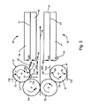
- the forme cylinder 31 is covered along its circumference with two printing plates 36 and the forme cylinder 33 in the same way with two printing plates 37 or at least assignable, wherein the printing plates 36; 37 z. B. one half the circumference of the forme cylinder 31; 33 corresponding length L have.
- the width B of the printing plates 36; 37 is u. a. depending on how many printing plates 36; 37 in the axial direction of the respective form cylinder 31; 33 are to be arranged.
- up to six printing plates 36; 37 may be arranged side by side.
- the form cylinders 31; 33 double-width and doppelumfnaturelich formed, whereas on the blanket cylinders 32; 34 arranged blankets the blanket cylinder 32; 34 z. B. fully encompass.
- At the leading end 03 of each printing plate 36; 37 is the opening angle ⁇ 1 between the folded suspension leg 13 and the extended length L of the printing plate 36; 37 preferably 45 °.
- each printing plate 36; 37 is the opening angle ⁇ 1 between the folded suspension leg 14 and the extended length L of the printing plate 36; 37 preferably 90 °.
- the slot width S in the form of cylinder 31; 33 introduced openings 09 is preferably 1 mm to 5 mm, in particular 3 mm.
- each printing forme magazine 38; 39 each have a receiving device 41; 42, z. B. a slot 41; 42, for receiving at least one of the respective forme cylinder 31; 33 ab broadlyden, used printing plate 36; 37 and a receiving device 43; 44, z. B.
- a shaft 43; 44 for receiving a on the respective form cylinder 31; 33 to be mounted, new printing plate 36; 37, wherein preferably each receiving device 41; 42; 43; 44 preferably a plurality of storage positions respectively for ab pointedde, used printing plates 36; 37 and for to be mounted, new printing plates 36; 37 has. While that the respective form cylinder 31; 33 associated printing form magazine 38; 39 z. B. by a pivoting movement of the respective form cylinder 31; 33 for changing a printing plate 36; 37 is employed, z. B. the first forme cylinder 31 and the second forme cylinder 33 of their respective operatively connected blanket cylinder 32; 34 turned off.
- the blanket cylinder 32; 34 be parked from the paper web 46. This is when changing one or more printing plates 36; 37, the relevant forme cylinder 31; 33 decoupled from the paper web 46, while in the printing unit, the other pair of cylinders 32; 34 can remain in production.
- the printing form magazines 38; 39 each extend preferably over the length of the bale of the forme cylinder 31; 33, but at least over the width B of the printing plate 36; 37, and in their respective shafts 41; 43 and 42, respectively; 44, a printing plate 36; 37 preferably completely, that is to record their length L after.
- the shafts 41; 43 and 42, respectively; 44 are z.
- the housing having an opening o38; o39, wherein the opening o38; o39 each parallel to the bale of the respective forme cylinder 31; 33 is alignable.
- the respective opening o38; o39 is a printing plate 36; 37, the forme cylinder 31; 33 can be fed or from this into the slot 41; 43 insertable.
- the openings o38; o39 the printing form magazines 38; 39 with respect to an opening 09 in the form of cylinders 31; 33 at a much smaller distance a38; a39 to the forme cylinder 31; 33 introduced as the length L of the printing plates 36; 37 is.
- the shafts 41; 43 and 42, respectively; 44 of the printing form magazines 38; 39 but at least the storage positions of the printing plates 36; 37, preferably oriented horizontally or with slight inclination, preferably with less than 15 ° relative to the horizontal H, wherein the openings o38; o39 the printing form magazines 38; 39 advantageously to one of the openings 09 in that form cylinder 31; 33, with which the respective printing forme magazine 38; 39 cooperates.
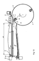
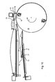
- a movably arranged printing form magazine 38; 39 is in its working position in front of a forme cylinder 31; 33 at its distance a38; a39 and its orientation to Shaped cylinder 31; 33 fixed by a lock 48 ( Fig. 5 ).
- the lock 48 may, for. B. done by a taper bolt z. B. with respect to the forme cylinder 31; 33 is stationary and in an opening in the housing of the printing forme magazine 38; 39 engages and a to the forme cylinder 31; 33 z. B. pivoted-up printing plate magazine 38; 39 with its openings o38; o39 with respect to the bale of the forme cylinder 31; 33 centered.
- the forme cylinder 31; 33 carriesregisterions in a predefined position to bring him z. B. with respect to the page register to zero, before there is an exchange of a printing plate 36; 37 between the forme cylinder 31; 33 and the printing form magazine 38; 39 is coming.
- the setting of the forme cylinder 31; 33 can also be the printing form magazine 38; 39 laterally relative to the forme cylinder 31; 33 are brought into a predefined position, so that the exchange of a printing plate 36; 37 between the printing form magazine 38; 39 and the forme cylinder 31; 33 can be targeted and without lateral displacement.
- an articulated, preferably pivotable baffle 49 in front of the opening of the printing forme magazine 39 which can be directed onto the forme cylinder 33, close to the forme cylinder 33 ( Fig. 5 ), with which a released from an opening 09 in the forme cylinder 33 trailing end 04 a printing forme 37 is directed to the shaft 42 for receiving the abinneden printing forme 37 is passed.
- an erroneous access to the shaft 44 is obstructed with the guide plate 49 for a printing plate 37 to be removed from the forme cylinder 33, in which at least one new printing plate 37 is provided or at least ready for delivery.
- the attachment of a guide plate 49 may be advantageous, but for the sake of clarity in the Fig. 5 not shown.
- FIG. 36 Another embodiment of a printing press with printing forme magazines results in conjunction with a printing machine, for.
- a printing machine for.
- a multi-color offset printing machine whose printing works preferably in bridge construction or a compact design, ie a low in construction height printing machine with eight pressure points, as exemplified by the Fig. 36 shows, in at least a frame 97 on a foundation 96 are arranged one above the other.
- a printing material 46 preferably a paper web 46, is in this case fed to the printing press and passed vertically through the printing units.
- each form cylinder 31; 33 is associated with at least one inking 94, the details of which will not be discussed here.
- Each form cylinder 31; 33 is a printing form magazine 38; 39, each preferably two shafts 41; 42; 43; 44 has.
- each printing forme magazine 38; 39 but at least its storage position for a printing form 36 to be stored; 37, in the working position preferably substantially horizontally or only with a slight inclination of less than 15 ° to the forme cylinder 31; 33 aligned.
- In the working position of the printing form magazine 38; 39 is at least one printing plate 36; 37 between the shafts 41; 42; 43; 44 and the forme cylinder 31; 33 interchangeable, either by a no longer required to execute a print job 36; 37 from the forme cylinder 31; 33 removed and into the shaft 41; Introduced 42 or a new to execute the print job printing plate 36; 37 from the shaft 43; 44 brought out and on the forme cylinder 31; 33 is mounted.
- the structural features of the printing form magazines 38; 39 may in this embodiment those of the previously in connection with the Fig. 5 correspond to described embodiment. It is advantageous if the implementation, in particular the completion of a printing form change is monitored by sensors. Likewise, the printing form magazines 38; 39 in conjunction with the form of cylinders 31; 33 controllable such that preferably from a printing press associated control station from selectively a printing plate change can be initiated. Because the printing form magazines 38; 39 during a running Production of the printing press can be prepared for a printing plate change, the standstill of the printing units requiring set-up reduced to an extremely short period of z. B. less than two minutes, preferably less than ninety seconds, for a complete change of all printing plates 36; 37 arranged in this printing press units.
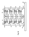
- FIG. 6 a forme cylinder 33 with two circumferentially offset by 180 ° channels 08 and two along the circumference of successively arranged printing plates 37, wherein the right-angled folded suspension legs 14 arranged at the trailing in the direction of production P of the forme cylinder 33 end 04 each printing plate 37 each of a channel 08, held by a spring element 22 pressurized holding means 21 on a wall 19, wherein the wall 19 extends from a rear edge 17 of the channel 08 opening opening 09 to the channel 08 out, the holding means 21 by the operation of a spring element 22 counteracting pneumatic Adjusting means 23 can be solved.
- Fig. 6 also shows an engageable by pneumatic actuation of the forme cylinder 33 pressure element 24 in the form of a pressure roller 24 or pressure roller 24.
- close to the forme cylinder 33 is a parallel to the axial direction pivotally mounted alignment device 51 with two diametrically arranged laterally on a printing plate 37, wing-shaped stops 52; 53 provided, wherein the Alignment device 51 each with one of their stops 52; 53, a printing plate 37 to be mounted temporarily fixed during its feeding to the forme cylinder 33.
- the stops 52; 53 z. B. each formed as a lateral guide plate, wherein the stops 52; 53 z. B. on a pivotable traverse, z. B. a square tube are arranged.
- the stops 52; 53 differ z. B.
- the stops 52; 53 may be axially adjustable to the forme cylinder 33 for the required width of the printing plate 37.
- FIGS. 6 to 35 embodiment shown is based on a variant of the printing forme magazine 39, in which an upper shaft 44 for providing a to be mounted on the forme cylinder 33 printing plate 37 as an independent unit independently of a lower slot 42 for receiving a form cylinder 33 removed print form 37 is operable. Both shafts 42; 44 can be used as individually and independently usable and thus independently functional units. This application is of interest if z. B. only the feed of the forme cylinder 33 is to be automated with new printing plates 37, whereas the decrease of used printing plates 37 is performed by an operator. If both shafts 42; 44 are formed in the printing forme magazine 39, results in a fully automatic printing form changer.
- Both shafts 42; 44 each have all necessary for storing and conveying of printing plates 37 devices and are preferably constructed very compact. In particular, they have despite their capacity of at least two printing plates 37 a low overall height.
- the height is z. B. less than 150 mm, preferably less than 100 mm.
- the shaft 44 is arranged horizontally and aligned tangentially to. Thereby, the gravity FG exerted on the printing plate 37 becomes supportive of functions described below used in the best possible way.
- a support 54 on which a to be mounted on the forme cylinder 33 first printing plate 37 with its folded EinHonbringeln 13; 14 can be set up or stored.
- a stored on the pad 54 printing form 37 is located there z. B. with their entire extended length L on.
- the pad 54 is preferably not the entire surface, but in the form of parallel strips 54 or slides 54 formed.
- the suspension leg 14 at the trailing end 04 of the first printing plate 37 is located in the shaft 44 on the side remote from the forme cylinder 33 on a preferably vertical stop 56, the stop 56 of a conveyor 57 linear and parallel to the support 54 in the direction of opening o39 the printing forme magazine 39 is movable in order to convey this first printing forme 37 out of the shaft 44 by a translatory movement and preferably without deformation until the suspension leg 13 can reach the slot-shaped opening 09 of the forme cylinder 33 at the leading end 03 of this first printing forme 37.
- the stopper 56 thus serves in the slot 44 for the first printing plate 37 as an abutment position and at the same time has the function of a slider 56.
- the stop 56 z. B. advantageously also as a perpendicular to the support 54 standing, connected to the conveyor 57 register pin 56 may be formed so that with the application of the first printing plate 37 on the stop 56 for them a Vorregisterung takes place with respect to their side register.
- the conveyor 57 is z. B. as a belt drive 57 or as a linear drive 57, preferably as a pneumatic linear actuator 57, in particular as a rodless, double-acting linear actuator 57 is formed.
- a holder 58 in particular printing form holder 58 for holding at least one second printing forme 37 to be mounted on the forme cylinder 33 Fig. 13 shown, the second printing plate 37 from the printing form holder 58 above the support 54, ie at a distance a54 above the support 54 z. B. thereby, that the printing form holder 58, for example, on the side facing away from the forme cylinder 33 has a movable parallel to the support 54 piston 59 or slider 59, at the end of a holding element 61, z. B.
- L-shaped angle 61 is arranged, wherein the second printing form 37 above the support 54 between the angle 61 of the extended slider 59 and a arranged in the region of the opening o39 of the printing forme magazine 39 further holding member 62, z. B. a rigidly arranged stop 62 is clamped.
- the distance a54 in this case has a value which is preferably between twice and four times the length 114 of the Einpurlegeels 14 at the trailing end 04 of the second printing plate 37.
- the clamping of the second printing forme 37 takes place in that a clear distance a58 between the angle 61 of the extended slider 59 and the stop 62 is set shorter than the extended length L of the second printing forme 37.
- the stop 62 in the region of the opening o39 of the printing forme magazine 39 preferably has a chamfer 63 on which the suspension leg 13 can be supported on the leading end 03 of the second printing plate 37, wherein the chamfer 63 of the stopper 62 and the L-shaped angle 61 at which the suspension leg 14 at the trailing end 04 the second printing form 37 is supported, facing each other. Since the second printing plate 37 is flexible, in particular along its length L, it bulges in its clamped state between the angle 61 and the stop 62.
- the slider 59 of the printing plate holder 58 is preferably linearly movable parallel to the support 54 and preferably has two stable operating positions, namely a stable operating position in the retracted, the second printing plate 37 releasing state and in the extended, ie the second printing plate 37 clamping state.
- the arrangement of the movable slide 59 and rigid stopper 62 are interchanged, so that the slider 59 is in the region of the opening o39 of the printing forme magazine 39 and the stop 62 on the side remote from the forme cylinder 33 side.
- the angle 61 or the stop 62 can also be arranged to be pivotable about a pivot axis aligned parallel to the width B of the printing forme 37.
- a clamped between the angle 61 and the stop 62 printing plate 37 is located at its upper or first storage position, while a stored on the pad 54 printing plate 37 assumes a lower, second storage position in this state, the printing plate 37 in the second storage position before her Transport to the forme cylinder 33 is cached.
- z. B. made by a belonging to the press control panel changes the printing plate 37 within the shaft 44 from its upper, first storage position to its lower, second storage position.
- Printing forms 37 stored in the first storage position and in the second storage position are spaced apart, e.g. B. along its length L with the distance a54, so they do not touch each other and therefore can not damage.
- Another embodiment of the printing plate holder 58 which advantageously allows a particularly low overall height for the shaft 44, provides the second printing forme 37 above the support 54 extending in a single plane in the axial direction of the forme cylinder 33 with at least one retaining element 64 in an upper storage position to hold, with the retaining element 64 z.
- a guide rail 64 preferably as two mutually parallel guide rails 64, is formed ( Fig. 7 to 9 ), wherein the guide rails 64 hold the second located in the slot 44 printing plate 37 at its two longitudinal sides along at least part of its length L in the upper storage position.
- the design of the printing form holder 58 with guide rails 64 assumes that the suspension legs 13; 14 at the ends 03; 04 of the second printing form 37 do not extend over the full width B of the printing plate 37 by not reaching the longitudinal sides of the printing plate 37.
- the longitudinal sides of the printing plate 37 thus form in the area of the support surface 02 of the printing plate 37 a projection with respect to the EinHonbringeln 13; 14. This projection is necessary to make the printing plate 37 in the guide rails 64 feasible.
- the holding element 64 in particular each guide rail 64, z. B. from a U-shaped, each one of the longitudinal sides of the printing plate 37 with a certain play encompassing strap into which the second printing forme 37 is inserted from the side facing away from the forme cylinder 33 side.
- the second printing form 37 is thus held by the guide rails 64, preferably in a narrow region of its side, wherein the holder acts in particular as a vertical support and thus as a support against the force acting on the printing plate 37 gravity FG.
- the guide rails 64 are preferably made of a dimensionally stable material such as metal or plastic.
- both guide rails 64 are movable in opposite directions, so they at least briefly remove each other and their distance from each other such that they no longer support the longitudinal sides of the printing plate 37 vertically, whereby the second printing plate 37 due to at its attacking gravity FG between the guide rails 64 passes through the support 54. If the holding element 64 in a first operating state, the second printing forme 37 z. B.
- the holding member 64 preferably changes remotely from its first operating state to a second operating state, the second operating state causes the holding member 64 that the printing plate 37 and the holding member 64 from each other and the printing forme 37 upon release from the retaining element 64 in the shaft 44 by a free fall and thus alone by the force acting on her gravity FG in the preferably immediately vertically below the upper storage position lying storage position changes.
- the second printing plate 37 is held in the lower and also in the upper storage position in the shaft 44 at an inclination of less than 15 °, preferably horizontally.
- At least the guide rails 64 designed as a support bearing for the second printing forme 37 have in their longitudinal extension only this slight inclination or a horizontal course.
- a release of the second printing forme 37 from the laterally engaging guide rails 64 is preferably supported by a stop 67 standing perpendicular to the support surface 02 of the second printing forme 37, which is preferably arranged rigidly in the slot 44, preferably on both longitudinal sides of the second printing forme 37 such stop 67 is arranged so that during a along the width B of the second printing form 37 directed, opposing movement of the printing plate 37 holding guide rails 64 this printing plate 37 by the stops 67 arranged on both sides in the of the support surface 02 of the printing form 37th spanned level remains stable.
- the stops 67 strip the printing plate 37 from the mutually removing guide rails 64 by the printing plate 37 abuts against the stops 67, at the same time the printing plate 37 by the movement of the guide rails 64, the vertical support is withdrawn.
- the release of the second printing plate 37 is preferably carried out by a z. B. controllable by the press belonging to the control station drive 69, the drive 69 acts on the guide rails 64 and moves them along a travel s68.
- the distance a67 preferably corresponds in terms of its value to a distance which is juxtaposed on the forme cylinder 33 in its axial direction, ie, adjacent pressure forms 37.
- printing plates 37 can be supplied with the conveyor 57 to the forme cylinder 33 either individually or preferably simultaneously, where the latter procedure for a rapid change of printing plates 37 on the forme cylinder 33 is advantageous.
- printing plates 37 can change simultaneously or at least in rapid succession in their respective second storage position.
- the form cylinder 33 at the same time jointly supplied printing plates 37 are arranged on the forme cylinder 33 in the axial direction side by side,
- each of these printing plates 37 is held at their longitudinal sides in a guide rail 64.
- the vertical offset of the printing plates 37 is only a few millimeters, z. B. 4 mm to 6 mm, and corresponds approximately to the overall height of the guide rails 64, preferably their simple to double height.
- the movement of the guide rails 64 along the width B of the second printing form 37 is z. B.
- a guide rail 64 z. B. attached to at least one pivot arm 68, the z. B. in the plane defined by the support surface 02 of the second printing plate 37 plane is pivotally, which in the Fig. 9 indicated by a directional arrow.
- the pivot arm 68 one end of which is connected to the guide rail 64 and the other end in the shaft 44 is preferably fixedly mounted, z. B.
- z. B. may be formed as a leaf spring 68, wherein the guide arm 64 connected to the pivot arm 68 by the drive 69, z. B. by a controllable, in particular remotely controllable magnet 69, in a second printing forme 37 holding or one of this printing plate 37 releasing operating position is moved.
- the travel s68, the movable guide rail 64 performs along the width B of the second printing plate 37, is in the range of a few millimeters, z. B. between 2 mm and 10 mm, preferably 4 mm.
- a stop 67 is also provided in this embodiment, to which the printing plate 37 abuts with its supported by the guide rail 64 side, while the guide rail 64 withdraws the support by their movement of the printing plate 37.
- Two adjacent pressure plates 37 in the axial direction of the forme cylinder 33 can strike on opposite sides of the same stop 67.
- the printing plate 37 can also with a their sides on the stop 67 vertically downward along slide, so that the released from the upper storage position printing plate 37 passes in a guided movement in the lower storage position.
- the stopper 67 then has the function of a preferably up to the support 54 reaching side guide for a memory position changing their printing form 37.
- a method of storing at least two of the same cylinder 06; 31; 33 of a printing press successively discharged elevators 01; 36; 37 the following steps: a) a previously from the cylinder 06; 31; 33 discharged elevator 01; 36; 37 is transported from a first to a second storage position, b) the previously discharged elevator 01; 36; 37 subsequently discharged elevator 01; 36; 37 is at the first storage position of the previously discharged elevator 01; 36; 37 stored, c) the previously discharged elevator 01; 36; 37 in its second storage position and the subsequently discharged elevator 01; 36; 37 in the first storage position of the previously discharged elevator 01; 36; 37 are stored in a distance orthogonal along their length L, d) the elevators 01; 36; 37 are stored in their respective support surface 02 at least largely overlapping, preferably at least 80% overlapping or stored in their complete or almost complete coverage.
- the previously discharged elevator 01; 36; 37 and the subsequently discharged elevator 01; 36; 37 are thereby stored along their length L vertically spaced from each other.
- the previously discharged elevator 01; 36; 37 transported by a linear movement, in particular by a both memory positions directly and directly interconnecting linear movement orthogonal to its support surface 02 or by a movement of its trailing end 04, in its second storage position, which will be explained in more detail below.
- each Printing form 37 mounted coding reads ie detects a feature for identifying a printing form to check in a preferably carried out electronically in a control unit with a provided for the forme cylinder 33, deposited in the control unit occupancy plan, if the introduced into the slot 44 printing plates 37th correspond to the allocation plan of the intended printing process and whether for the intended occupancy introduced into the slot 44 printing plates 37 are also in the correct order.
- a corresponding message eg. B. an error message, ie a warning the operator before a faulty installation message generated and z. B. deposited on a printing unit associated control station and displayed there or on the printing unit.
- the coding may preferably be in addition to a human-readable code z. B. be designed as a barcode.
- the code reader 71 is thus preferably arranged in the shaft 44 at its end facing away from the forme cylinder 33, wherein a reading direction of the code reader 71 is directed either parallel to the length L of the printing plate 37 or preferably parallel to the width B of the printing plate 37.
- the code reader 71 is preferably arranged with a linear guide movable in or on the shaft 44 or there is a preferably inclined by 45 ° to the width B of the printing plate 37 movable mirror which provides a detection or read signal from one to the printing plate 37 attached code to a arranged on one side of the shaft 44 code reader 71 deflects, so that only a single code reader 71 is required for reading the attached to the stored in the wells 44 printing plates 37 coding.
- significant costs can be saved.
- the code reader 71 or the mirror is either parallel to the width B of the printing plate 37, ie in the axial direction of the forme cylinder 33, preferably along several shafts 44 and / or along the pressure forms stacked in one of the shafts 44 37 vertically movable so that the code reader 71 or the mirror detects the coding of stored in different storage positions printing forms 37.
- Either the code reader 71 or at least one other sensor 91 may be used to monitor and / or to check whether an intended printing plate change has been carried out successfully.
- Errors such as a double occupancy or a faulty occupancy, ie the assembly of a printing plate 37 at an inaccurate location, are then avoidable, but at least detectable by a preferably deposited on the control station of the printing machine message before a greater damage occurs.
- a further shaft 42 which serves the recording of the forme cylinder 33 remote printing plates 37.
- This slot 42 has a z. B. inclined support 72, which as well as the support 54 in the shaft 44 to provide on the forme cylinder 33 to be mounted printing plates 37 is preferably not formed over the entire surface, but in the form of parallel strips 72 or slides 72, wherein the inclination of the support 72 the Shaft 42 preferably expands on the side facing away from the forme cylinder 33, whereby this shaft 42 is more accessible to the operator on the side facing away from the forme cylinder 33, which facilitates the removal of stored in the slot 42 printing plates 37.
- the support 72 in the shaft 42 is z. B.
- the shaft 42 for receiving the forme cylinder 33 remote printing plates 37 is below a shaft 44 for providing on the forme cylinder 33 to be mounted printing plates 37, which is a preferred, but not mandatory arrangement.
- the shafts 42; 44 may also be layered in reverse order or may be separate.
- a preferred embodiment of the shaft 42 provides that in the shaft 42 in the axial direction of the forme cylinder 33 next to each other at least two printing plates 37 can be stored. This embodiment allows a particularly rapid removal of printing plates 37, in particular when at least two printing plates 37 can be arranged on the forme cylinder 33 in its axial direction, because a plurality of printing plates 37 can be removed simultaneously from the forme cylinder 33. If on the forme cylinder 33 in its axial direction z. B. at least four printing plates 37 can be arranged are, it is advantageous for stability reasons, for. B. two shafts 42 in the axial direction of the forme cylinder 33 next to each other.
- Each defined by the width B of a printing plate 37 storage space in one of these shafts 42 is then formed such that there are at least as many printing plates 37 can be stored as printing plates 37 can be arranged on the forme cylinder 33 along its circumference, wherein the storage of the printing plates 37 at each storage space on top of each other in a stack. It can be provided that in each of the shafts 42 up to ten, but at least up to eight printing plates 37 can be stored so that discharged from the forme cylinder 33 printing plates 37 can be collected in the shafts 42 and the shafts 42 is not necessarily after each change of the printing plates 37 must be cleared by the operator. Regardless of the number of juxtaposed wells 42, the storage locations in the axial direction of the forme cylinder 33 have the same close spacing from each other as the printing formes 37 are arranged on the forme cylinder 33.
- a distance a73 of the guide element 73 from the lateral surface 07 of the forme cylinder 33 is preferably not much greater than the length 114 of the folded Einsconbringels 14 at the trailing end 04 of the printing plate 37, in particular, the distance a73 of the guide member 73 has a value between the simple and the double Length 114 of the suspension rack 14 on ( Fig. 6 ). Since a printing forme 37 to be removed from the forme cylinder 33 touches the guide element 73 with its printed image side, its contact with a rotatably mounted rolling element 73 is gentler on its surface than sliding over a flat rigid wedge 73. This aspect is of particular importance when the printing form 37 to be used again and thus damage to their printed image page by scratches or grinding marks is to be avoided.
- a sensor 91 may be mounted, either in contact with the forme cylinder 33 to be removed from the printing plate 37 or advantageously contactless, z. B. inductive, checks whether the suspension leg 14 has actually solved at the trailing end 04 of the forme cylinder 33 to be removed from the printing forme 37 after actuation of the arranged in the channel 08 of the forme cylinder 33 holding means 21. With its test, the sensor 91 sends a signal z. B. to the press belonging to the control room. On the basis of the signal emitted by the sensor 91, a decision is made as to whether the process of discharging a printing forme 37 to be removed from the forme cylinder 33 can be continued or whether measures for eliminating a malfunction must be initiated.
- a plurality of sensors 91 are provided in the axial direction of the forme cylinder 33, for. B. four or six, namely in each case at least one sensor 91 for each on the forme cylinder 33 in the axial direction next to each other can be arranged printing form 37th
- the suspension leg 14 at the trailing end 04 of the printing forme 37 to be removed from the forme cylinder 33 preferably passes on a first ramp 74 spaced from the guide element 73 before reaching the support 72 in the shaft 42, wherein the first ramp 74 initially rises in the direction of the support 72 and, after a summit point 76, drops towards the support 72.
- the first ramp 74 is preferably rigidly connected to the support 72.
- a77 (a) is at a short distance.
- Fig. 14 arranged behind the summit point 78 with the second ramp 77 rigidly connected stop 79 to which the suspension leg 14 abuts the trailing end 04 of the printing plate 37.
- the distance a77 has a value of a few millimeters, preferably a value of less than the single length 114, In particular, less than half the length 114 of the folded Einitatiwingels 14 at the trailing end 04 of the printing plate 37.
- the second ramp 77 and the stop 79 connected to it are linearly movable by a conveyor 81 and parallel to the support 72 in order to completely convey the printing forme 37 to be removed from the forme cylinder 33 into the shaft 42.
- the conveyor 81 which forms in particular together with the steep flank on the second ramp 77 for the folded suspension leg 14 at the trailing end 04 of the printing plate 37, a printing forme 37 in the slot 42 promoting entrainment is z. B.
- Both the first ramp 74 and the second ramp 77 consist z. B. not from full-surface planes, but from several parallel as the tines of a comb arranged guide rails.
- the second ramp 77 may, for. B. be formed from one or more correspondingly bent metal strip.
- a lifter 82 in particular a printing form lifter 82 is arranged in the shaft 42, wherein the printing form lifter 82, for example, a preferably perpendicular to the support 72 movable piston 83, at the end of a z.
- L-shaped, in particular U-shaped lifting arm 84 is arranged, wherein the bent suspension leg 14 is set up at the trailing end 04 of the printing plate 37 on the lifting arm 84 or set encompassing.
- the printing form lifter 82 preferably has two stable operating positions, namely a stable operating position with the piston 83 retracted, in which the lifting arm 84 is below the level defined by the support 72, and another stable operating position with the piston 83 extended, in which the lifting arm 84 the printing forme 37 removed from the forme cylinder 33 lifts from the support 72.
- the printing form lifter 82 performs a stroke s82 which is greater than that Length 114 of the folded Einsconbringels 14 at the trailing end 04 of the printing plate 37.
- the stroke s82 has a value between the single and double the length l14 of Einnosnlegeels 14 on.
- the printing form lifter 82 thus lifts a printing forme 37 removed from the forme cylinder 33 from a provisional first storage position to a final, second storage position.
- a preferably pivotable about a substantially parallel to the width B of the printing plate 37 extending pivot axis securing element 86 is arranged, for. B. in the form of a strip-shaped flap 86, whose or the lower edge is located at a distance a86 from the lifting arm 84, wherein the distance a86 is preferably dimensioned smaller than the length l14 of the folded Einitatibelt 14 at the trailing end 04 of the printing plate 37th
- Fig. 6 indicates a direction arrow to the pivoting of the fuse element 86.
- the securing element 86 secures a printing form 37 lifted by the printing form lifter 82 against unintentional slippage in the shaft 42 or removal from the shaft 42. Thus, an operator first has to pivot the securing element 86 before the raised printing form 37 can be removed from the shaft 42.
- FIG. 10 Another embodiment of arranged in the shaft 42 assemblies is in the 10 to 12 shown.
- This embodiment provides a preferably rigidly arranged in the central region of the support 72 stop 79, wherein a linearly along the support 72 movable conveyor 81 associated printing form lifter 82 the folded suspension leg 14 at the trailing end 04 of a forme cylinder 33 to be removed printing plate 37 on the Stop 79 raises and the printing forme 37 pulls on its folded suspension leg 14, preferably in its raised state from the printing form lifter 82 state to the side facing away from the forme cylinder 33 end of the shaft 42.
- the conveyor 81 and the printing form lifter 82 can be forcibly coupled in such a way that the printing form lifter 82 then lifts the folded suspension leg 14 of the printing plate 37 as soon as the conveying device 81 moves in the direction away from the forme cylinder 33 performs. Furthermore, a further printing form lifter 87 is provided between the stop 79 and the forme cylinder 33 facing the end of the shaft 42, which raises the leading end 03 of a form cylinder 33 remote, inserted into the slot 42 printing form 37 so far that another from the forme cylinder 33rd to be removed printing form 37 between the support 72 and the raised printing plate 37 into the slot 42 is inserted.
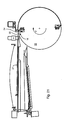
- the forme cylinder 33 rotates the opening 09 of a channel 08, in which the suspension leg 14 is held at the trailing end 04 of the forme cylinder 33 to be removed from the printing plate 37 by a holding means 21, in a first position, which is below the guide 42 belonging to the lower guide member 73 is located.
- the controllable, preferably pneumatically actuable pressure element 24 is set to the forme cylinder 33 ( Fig. 13 ).
- the preferably pneumatically actuable actuating means 23 pivots the holding means 21 against the force of a spring element 22, whereby the suspension leg 14 at the trailing end 04 of the printing plate 37 due to its elastic residual stress from the opening 09 snaps and abuts the guide member 73.
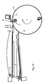
- the employed pressing element 24 secures the printing forme 37 against a further release from the lateral surface 07 of the forme cylinder 33 (FIG. Fig. 14 ).
- the forme cylinder 33 rotates counter to its production direction P and pushes the trailing end 04 of the printing forme 37 into the shaft 42
- Printing form 37 in the slot 42 of the suspension leg 14 slides at the trailing end 04 of this printing plate 37 along the guide member 73 along and then turns on the shaft 42 belonging to the first ramp 74.
- the suspension leg 14 slides up the ramp 74 to above its summit point 76 and then reaches the support 72.
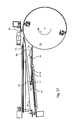
- the pressing member 24 is still employed on the forme cylinder 33
- the printing plate 37 is further rotated into the shaft 42 by the rotation of the forme cylinder 33 against its production direction P. inserted.
- their suspension legs 14 at the trailing end 04 also overcomes the second ramp 77 connected to the conveying device 81 and abuts against the stop 79 connected to the second ramp 77 (FIG. Fig. 15 ).
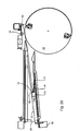
- the pressing element 24 is turned off by the forme cylinder 33.
- the pressure plate 37 is now with its leading End 03 free on the lateral surface 07 of the forme cylinder 33 on.
- the forme cylinder 33 has performed less than half a turn from loosening the suspension leg 14 at the trailing end 04 until now.
- the folded suspension leg 14 at the trailing end 04 has hooked between the second ramp 77 and the stop 79.
- the conveying device 81 connected to the second ramp 77 and the stop 79 can now completely feed the printing plate 37 into the shaft 42 (FIG. Fig. 16 ).
- the printing forme 37 is removed from the forme cylinder 33 and is in its length L in the shaft 42. its suspension leg 14 at the trailing end 04 rests on the summit point 78 of the second ramp 77, while its leading end 03 on the summit point 76 of the first ramp 74th rests, whereby at least the suspension leg 13 preferably hangs freely at the leading end 03.
- the storage of the printing plate 37 in the shaft 42 is thus preferably carried out by a support at two points, namely on the summit points 76; 78 of the two ramps 74; 77 ( Fig. 17 ).
- the z. B. pneumatically actuated Druckformheber 82 lifts the retracted into the slot 42 printing plate 37 at its trailing end 04 to just below the fuse element 86, wherein the suspension leg 14 stands up on the associated with the printing forme lifter 82 lifting arm 84 ( Fig. 18 ).
- the forme cylinder 33 While a first to be mounted on the forme cylinder 33 printing forme 37 with its folded Einffenbringeln 13; 14 rests on the support 54 in the upper shaft 44, the forme cylinder 33 continues to rotate counter to its production direction P in a second position until the opening 09, from which the suspension leg 13 at the leading end 03 of the previously removed from the forme cylinder 33 printing plate 37 has been solved has passed a contact point 88 of the pressure element 24 applied to the forme cylinder 33 and the rear edge 17 of the opening 09 in the production direction P of the forme cylinder 33 is at a distance a88 from the contact point 88, the distance a88 being in the range of a few millimeters, preferably is less than 30 mm, and thus corresponds to an arc length of less than a thirtieth part of the circumference of the forme cylinder 33.
- the first position of the forme cylinder 33 for removing a printing plate 37 arranged thereon is generally not identical with its second position for receiving a new printing forme 37.
- the pressing element 24 is preferably applied to the forme cylinder 33, while the opening 09 passes the contact point 88 or after passing the contact point 88.
- the alignment device 51 which is arranged close to the forme cylinder 33, pivots with its previously preferably horizontally oriented diametrical stops 52; 53 preferably by 90 ° in a vertical position, so that a matched to the width B of the forme cylinder 33 to be mounted on the printing plate 37 stop 52; 53 immersed in a defined by the support 54 in the shaft 44 transport plane for the mounted on the forme cylinder 33 printing plate 37 and immersed on the forme cylinder 33 to be mounted printing plate 37 during its transport from the slot 44 to the stop 52; 53 page register moderately aligned to the forme cylinder 33 ( Fig. 19 ).
- the first printing forme 37 to be mounted on the forme cylinder 33 stands with its suspension leg 14 at its trailing end 04 on with a conveying device 57 connected stop 56 at.
- the conveyor 57 is set in operation, so that the stop 56 in a direction preferably directed tangentially to the forme cylinder 33, the first printing form 37 as far from the shaft 44 moves until its leading end 03 touches the An exertenelement 24 attached to the forme cylinder 33 and the this leading end 03 be bent suspension legs 13 between the rear in the direction of production P of the forme cylinder 33 edge 17 of the opening 09 and the contact point 88 of the pressure element 24 on the forme cylinder 33 ( Fig. 20 ).
- the forme cylinder 33 changes its direction of rotation and begins to rotate in its production direction P, whereby the suspension leg 13 set up on the forme cylinder 33 slips into the opening 09 at the leading end 03 of the printing forme 37 and preferably hooks positively onto the front edge 16 of the opening 09 ( Fig. 21 ).
- the printing forme 37 which is suspended with its suspension leg 13 in the opening 09, is completely conveyed out of the shaft 44 and mounted on the forme cylinder 33.
- the printing forme 37 is rolled onto the forme cylinder 33 by the pressing element 24 placed against the forme cylinder 33.
- the pressing element 24 presses the folded suspension leg 14 at the trailing end 04 of the printing forme 37 into the opening 09.
- the retaining means 21 in the channel 08 belonging to this opening 09 has been released and is then inserted into the one Operating position brought in which it introduced into the opening 09 suspension leg 14 at the trailing end 04 of the printing forme 37 z. B. fixed by a clamp.
- the conveyor 57 drives the stop 56 connected to it again into its end position on the side remote from the forme cylinder 33 in the shaft 44 (FIG. Fig. 22 ).
- the pressure element 24 is turned off by the forme cylinder 33 and the alignment device 51 pivots with its diametrical stops 52; 53 again preferably in one horizontal position.
- a change of a first printing plate 37 on the forme cylinder 33 is completed by a used printing plate 37 removed and a new printing plate 37 was mounted.
- This change of a printing plate 37 can be completed with the described device in a very short time, preferably in less than a minute.
- the forme cylinder 33 is then ready for production again ( Fig. 23 ).
- the change of another, z. B. on the forme cylinder 33 along its circumference arranged second printing form 37 begins with the fact that preferably during the previous ongoing production of an operator, the new second printing plate 37 is inserted into the slot 44.
- the second printing form 37 is held by a controllable, preferably pneumatically controllable printing form holder 58 on the support 54 by the printing forme 37 z. B. either at their ends 03; 04 between two stops 61; 62 is clamped, wherein at least one of the stops 61; 62 is movable, or by the printing plate 37 is inserted at its longitudinal sides in guide rails 64, wherein at least one of the guide rails 64 along the width B of the printing plate 37 is movable.
- the printing form holder 58 releases the printing plate 37 by its holding the printing plate 37 elements, for. B. the stops 61; 62 or the guide rails 64, their distance, z. B. a58, each other at least briefly increase, the printing plate 37 falls on the support 54 and is there with their Einhotbringeln 13; 14 on ( Fig. 24 ).
- the forme cylinder 33 rotates according to the Fig. 13 explained method, the opening 09 of the channel 08, in which the suspension leg 14 is held at the trailing end 04 of the forme cylinder 33 to be removed second printing plate 37 by a holding means 21, in the first position, which is below the lower shaft 42 belonging to guide member 73rd located.
- the controllable, preferably pneumatically actuable pressure element 24 is set to the forme cylinder 33 ( Fig. 25 ).
- the method explained pivots the preferred pneumatically actuatable adjusting means 23, the holding means 21 against the force of the spring element 22, whereby the suspension leg 14 at the trailing end 04 of the second printing form 37 due to its elastic residual stress from the opening 09 snaps and abuts the guide member 73.
- the employed pressing element 24 secures the second printing forme 37 against further release from the lateral surface 07 of the forme cylinder 33 (FIG. Fig. 26 ).
- the forme cylinder 33 rotates counter to its production direction P and thereby pushes the trailing end 04 of the second printing form 37 into the shaft 42.
- the suspension leg 14 first slides along the trailing end 04 of this printing plate 37 along the guide element 73 and then positions itself on the first ramp 74 belonging to the shaft 42.
- the suspension leg 14 of the second printing form 37 slides up the ramp 74, wherein it slides under the resting in the shaft 42, resting on the summit point 76 of the first ramp 74 first printing plate 37 and the summit point 76 overhanging, directed to the forme cylinder 33 leading end 03rd lifts, while the suspension leg 14 of the second printing form 37 exceeds the summit point 76 of the first ramp 74 and then reaches the support 72.
- the second printing forme 37 is pushed further into the slot 42 by the rotation of the forme cylinder 33 counter to its production direction P.
- the suspension leg 13 slides at the leading end 03 of resting in the shaft 42 first printing plate 37 on the printed image side of the shaft 42 promoted second printing plate 37.
- the suspension leg 14 overcomes at the trailing end 04 of the second printing plate 37auchauch with the conveyor 81st connected second ramp 77 and abuts against the second ramp 77 connected to stop 79 ( Fig. 27 ).
- the pressing element 24 is turned off by the forme cylinder 33.
- the preferably positive locking at the front edge 16 of the opening 09 hinged folded suspension hooks 13 dissolves at the leading end 03 of the second printing form 37th from the opening 09.
- the suspension leg 13 with its leading end 03 is now free on the lateral surface 07 of the forme cylinder 33.
- the forme cylinder 33 has performed from loosening the Einnosnlegeels 14 at the trailing end 04 until now again less than half a turn.
- the bent suspension leg 14 at the trailing end 04 hooks between the second ramp 77 and the stop 79 a.
- the lifting arm 84 of the printing form lifter 82 lowers, as a result of which the first printing plate 37 resting on its trailing end 04 and resting in the shaft 42 is deposited on a web 89 formed on the stop 79, wherein the web 89 is perpendicular to the rest 72 Height h89, the value of which is greater than the length l14 of the folded EinHonbringels 14 at the trailing end 04 of the second printing plate 37.
- the height h89 preferably has a value between the single and double length 114 of the folded Einhotbringels 14 at the trailing end 04 of the second printing form 37 on ( Fig. 28 ).
- the conveying device 81 connected to the second ramp 77 and the stop 79 now pulls the second printing plate 37 completely into the slot 42, with the first and second printing plates 37 being arranged in the slot 42 of their length L one above the other.
- the conveyor device 81 forms together with the second ramp 77 and the stop 79 for the folded suspension leg 14 at the trailing end 04 of the introduced into the slot 42 printing plate 37 a driver device ( Fig. 29 ).
- the printing form lifter 82 now lifts with its lifting arm 84, preferably the trailing end 04 of both arranged in the shaft 42 printing plates 37 to the fuse element 86 at.
- the leading end 03 of the second printing plate 37 rests with a directed to the forme cylinder 33 overhang on the summit point 76 of the first ramp 74 and the folded suspension leg 13 at the leading end 03 of the first printing plate 37 is on the leading end 03 of the second printing plate 37 ( Fig. 30 ).
- the contact point 88 of the form cylinder 33 employed pressure element 24 has passed and in the production direction P of the forme cylinder 33rd the rear edge 17 of the opening 09 is located at a distance a88 from the contact point 88, wherein the distance a88 is in the range of a few millimeters, preferably less than 30 mm, and thus corresponds to an arc length of less than a thirtieth part of the circumference of the forme cylinder 33 ( Fig. 19 ).
- the pressing member 24 is preferably made to the forme cylinder 33, while the opening 09 passes the contact point 88 or after it has passed the contact point 88.
- the alignment device 51 which is arranged close to the forme cylinder 33, pivots with its previously preferably horizontally oriented diametrical stops 52; 53, preferably by 90 ° in a vertical position, so that a matched to the width B of the forme cylinder 33 to be mounted on the second printing plate 37 stop 52; 53 immersed in a defined by the support 54 in the shaft 44 transport plane for the second printing plate 37 to be mounted on the forme cylinder 33 and the second printing forme 37 to be mounted on the forme cylinder 37 during its transport from the shaft 44 to the stop 52; 53 page register moderately aligned to the forme cylinder 33 ( Fig. 31 ).
- the second printing forme 37 to be mounted on the forme cylinder 33 rests with its suspension leg 14 at its trailing end 04 on the stop 56 connected to the conveying device 57.
- the conveyor 57 is put into operation, so that the stop 56 in a direction preferably directed tangentially to the forme cylinder movement 33 the second printing form 37 so far from the shaft 44 until its leading end 03 touches the Anhaltelement 24 employed on the forme cylinder 33 and the suspension leg 13 bent at this leading end 03 rises between the rear edge 17 of the opening 09 and the contact point 88 of the pressure element 24 on the forme cylinder 33 in the direction of production P of the forme cylinder 33 ( Fig. 32 ).
- the second printing forme 37 which is suspended by its suspension leg 13 in the opening 09, is completely conveyed out of the shaft 44 and drawn onto the forme cylinder 33.
- the second printing plate 37 is rolled onto the forme cylinder 33 by the pressing element 24 placed against the forme cylinder 33.
- the pressing member 24 presses the folded suspension leg 14 at the trailing end 04 of the second printing form 37 in the opening 09.
- the holding means 21 in the channel 08 associated with this opening 09 was released and is then in brought that operating position in which it introduced into the opening 09 suspension leg 14 at the trailing end 04 of the second printing forme 37 z.
- the conveyor 57 drives the stop 56 connected to it again into its end position on the side remote from the forme cylinder 33 in the shaft 44.
- the upper shaft 44 is now empty, whereas two used printing plates 37 are deposited in the lower shaft 42 (FIG. Fig. 34 ).
- the pressure element 24 is turned off by the forme cylinder 33 and the alignment device 51 pivots with its diametrical stops 52; 53 again preferably in a horizontal position.
- the change of a second printing plate 37 on the plate cylinder 33 is completed by a used second printing plate 37 first removed and a new second printing plate 37 was mounted.
- the forme cylinder 33 is ready for production again.
- This change can be completed with the device described in less than a minute.
- the change of a first and a second printing plate 37 can thus be completed in less than two minutes, preferably in less than ninety seconds ( Fig. 35 ).
Landscapes
- Supply, Installation And Extraction Of Printed Sheets Or Plates (AREA)
- Rotary Presses (AREA)
- Folding Of Thin Sheet-Like Materials, Special Discharging Devices, And Others (AREA)
- Inking, Control Or Cleaning Of Printing Machines (AREA)
- Maintenance And Inspection Apparatuses For Elevators (AREA)
- Basic Packing Technique (AREA)
- Beverage Vending Machines With Cups, And Gas Or Electricity Vending Machines (AREA)
- Devices For Checking Fares Or Tickets At Control Points (AREA)
- Automatic Disk Changers (AREA)
- Elevator Control (AREA)
Claims (11)
- Procédé pour stocker un habillage (01 ; 36 ; 37) à retirer d'un cylindre (06 ; 31 ; 33) d'une machine à imprimer, avec une extrémité avant (03) et une extrémité arrière (04), l'habillage (01 ; 36 ; 37) retiré du cylindre (06 ; 31 ; 33) étant stocké sur sa longueur (L), sous un angle d'inclinaison (δ) maximal de 15° par rapport à une horizontale (H), caractérisé en ce que l'habillage (01 ; 36 ; 37) à stocker est levé, avec un leveur (82), d'une première position de stockage, provisoire, en une deuxième position de stockage finale, le leveur (82) levant l'habillage (01 ; 36 ; 37) à stocker, à son extrémité arrière (04), de la première position de stockage en la deuxième position de stockage, tandis que l'extrémité avant (03) de cet habillage (01 ; 36 ; 37) à stocker repose sur un palier d'appui.
- Procédé selon la revendication 1, caractérisé en ce que l'habillage (01 ; 36 ; 37) à stocker, levé à sa deuxième position de stockage finale est assuré à l'aide d'un élément de sécurité (86) contre tout ripage ou contre un échappement intempestif hors de sa position de stockage finale.
- Procédé selon la revendication 1, caractérisé en ce qu'au moins un deuxième habillage (01 ; 36 ; 37) de la machine à imprimer est enlevé du même cylindre (06 ; 31 ; 33) de la machine à imprimer, les habillages (01 ; 36 ; 37) étant retirés les uns à la suite des autres, un habillage (01 ; 36 ; 37), retiré, avant un habillage suivant, du cylindre (06 ; 31 ; 33) étant transporté de sa première à sa deuxième position de stockage.
- Procédé selon la revendication 3, caractérisé en ce que l'habillage (01 ; 36 ; 37), retiré, suivant l'habillage du cylindre (06 ; 31 ; 33) retiré précédemment, étant stocké à la première position de stockage de l'habillage (01 ; 36 ; 37) retiré précédemment.
- Procédé selon la revendication 4, caractérisé en ce que l'habillage (01 ; 36 ; 37) retiré précédemment est stocké à sa deuxième position de stockage et l'habillage (01 ; 36 ; 37) retiré ensuite est stocké à la première position de stockage de l'habillage (01 ; 36 ; 37) retiré précédemment, sous un espacement orthogonal le long de sa longueur (L).
- Procédé selon la revendication 5, caractérisé en ce que les habillages (01 ; 36 ; 37) sont stockés en se recouvrant au moins pour une grande partie dans leur surface de pose (02) respective.
- Procédé selon la revendication 3, caractérisé en ce que l'habillage (01 ; 36 ; 37) retiré précédemment est transporté de sa première position de stockage à sa deuxième position de stockage au moyen d'un déplacement linaire.
- Procédé selon la revendication 7, caractérisé en ce que le déplacement linéaire s'effectue perpendiculairement à la surface de pose (02) de l'habillage (01 ; 36 ; 37) retiré précédemment.
- Procédé selon la revendication 6, caractérisé en ce que l'habillage (01 ; 36 ; 37) retiré précédemment et l'habillage (01 ; 36 ; 37) retiré ensuite sont stockés de manière que leurs surfaces de pose (02) respectives se recouvrent au moins à 80%.
- Procédé selon la revendication 6, caractérisé en ce que l'habillage (01 ; 36 ; 37) retiré précédemment et l'habillage (01 ; 36 ; 37) retiré ensuite sont stockés de manière que leurs surfaces de pose (02) respectives se recouvrent à peu près complètement.
- Procédé selon la revendication 1, caractérisé en ce que l'habillage (01 ; 36 ; 37) à stocker, reposant, par son extrémité avant (03), sur le palier d'appui, est monté en surplombant librement, par son extrémité avant (03), un point d'appui du palier d'appui.
Applications Claiming Priority (2)
| Application Number | Priority Date | Filing Date | Title |
|---|---|---|---|
| DE10314343A DE10314343B4 (de) | 2003-03-28 | 2003-03-28 | Vorrichtung zum Speichern eines an einem Zylinder einer Druckmaschine auszutauschenden Aufzugs |
| EP04712580A EP1608512B1 (fr) | 2003-03-28 | 2004-02-19 | Dispositif et procede de stockage d'au moins deux blanchets evacues successivement du meme cylindre d'une presse |
Related Parent Applications (2)
| Application Number | Title | Priority Date | Filing Date |
|---|---|---|---|
| EP04712580.2 Division | 2004-02-19 | ||
| EP04712580A Division EP1608512B1 (fr) | 2003-03-28 | 2004-02-19 | Dispositif et procede de stockage d'au moins deux blanchets evacues successivement du meme cylindre d'une presse |
Publications (2)
| Publication Number | Publication Date |
|---|---|
| EP1938986A1 EP1938986A1 (fr) | 2008-07-02 |
| EP1938986B1 true EP1938986B1 (fr) | 2010-03-10 |
Family
ID=33016078
Family Applications (4)
| Application Number | Title | Priority Date | Filing Date |
|---|---|---|---|
| EP08150722A Expired - Lifetime EP1938986B1 (fr) | 2003-03-28 | 2004-02-19 | Procédé pour stocker et pour décharger un revêtement d'un cylindre d'une presse |
| EP08150712A Expired - Lifetime EP1930164B1 (fr) | 2003-03-28 | 2004-02-19 | Procédé pour stocker d'un revêtement d'un cylindre d'une presse utilisant un senseur |
| EP07114286.3A Expired - Lifetime EP1862306B2 (fr) | 2003-03-28 | 2004-02-19 | Procédé pour décharger un blanchet d'un cylindre d'une presse |
| EP04712580A Expired - Lifetime EP1608512B1 (fr) | 2003-03-28 | 2004-02-19 | Dispositif et procede de stockage d'au moins deux blanchets evacues successivement du meme cylindre d'une presse |
Family Applications After (3)
| Application Number | Title | Priority Date | Filing Date |
|---|---|---|---|
| EP08150712A Expired - Lifetime EP1930164B1 (fr) | 2003-03-28 | 2004-02-19 | Procédé pour stocker d'un revêtement d'un cylindre d'une presse utilisant un senseur |
| EP07114286.3A Expired - Lifetime EP1862306B2 (fr) | 2003-03-28 | 2004-02-19 | Procédé pour décharger un blanchet d'un cylindre d'une presse |
| EP04712580A Expired - Lifetime EP1608512B1 (fr) | 2003-03-28 | 2004-02-19 | Dispositif et procede de stockage d'au moins deux blanchets evacues successivement du meme cylindre d'une presse |
Country Status (8)
| Country | Link |
|---|---|
| US (2) | US7530309B2 (fr) |
| EP (4) | EP1938986B1 (fr) |
| JP (1) | JP4361058B2 (fr) |
| CN (2) | CN101497257B (fr) |
| AT (4) | ATE411171T1 (fr) |
| DE (7) | DE10314343B4 (fr) |
| ES (1) | ES2324431T3 (fr) |
| WO (1) | WO2004085158A2 (fr) |
Families Citing this family (9)
| Publication number | Priority date | Publication date | Assignee | Title |
|---|---|---|---|---|
| DE102005029167A1 (de) | 2005-06-23 | 2006-12-28 | Maschinenfabrik Wifag | Druckzylinderbelag, Kombination aus Druckzylinder und Druckzylinderbelag sowie Druckzylinder mit klemmend befestigtem Druckzylinderbelag |
| DE102006006136A1 (de) | 2006-02-10 | 2007-08-23 | Koenig & Bauer Aktiengesellschaft | Systeme zur Überprüfung der Bestückung eines Druckformmagazins und ein System zur Zuführung mindestens einer in einem Druckformmagazin gespeicherten Druckform zu einem Zylinder |
| DE102006032202B3 (de) * | 2006-07-12 | 2007-10-11 | Koenig & Bauer Aktiengesellschaft | Speichervorrichtung für Druckplatten |
| DE102006061295A1 (de) * | 2006-09-01 | 2008-03-20 | Koenig & Bauer Aktiengesellschaft | Verfahren zum registerhaltigen Montieren einer biegsamen Druckform auf einem Formzylinder einer Rotationsdruckmaschine |
| DE102008000495B4 (de) * | 2008-03-03 | 2011-09-29 | Koenig & Bauer Aktiengesellschaft | Vorrichtungen für eine Rotationsdruckmaschine mit mindestens einem Speicherfach |
| US8736358B2 (en) | 2010-07-21 | 2014-05-27 | Macronix International Co., Ltd. | Current source with tunable voltage-current coefficient |
| FR2986180B1 (fr) * | 2012-01-27 | 2014-12-19 | Goss Internat France | Dispositif de chargement des plaques d'impression sur un cylindre porte-plaque d'une presse rotative offset |
| FR2989928A1 (fr) * | 2012-04-27 | 2013-11-01 | Goss Int Corp | Procede de stockage de plaques d'impression retirees successivement d'un cylindre porte-plaque d'une presse rotative et dispositif de stockage |
| DE102016201137B4 (de) * | 2016-01-27 | 2018-12-27 | Kba-Metalprint Gmbh | Vorrichtung zum Bedrucken von Hohlkörpern |
Family Cites Families (37)
| Publication number | Priority date | Publication date | Assignee | Title |
|---|---|---|---|---|
| JPS5932311B2 (ja) | 1976-06-14 | 1984-08-08 | リヨ−ビ株式会社 | オフセツト印刷機等の給版装置 |
| DE3270412D1 (en) * | 1982-08-10 | 1986-05-15 | Mitsubishi Heavy Ind Ltd | Printing plate exchange system |
| JPH0669749B2 (ja) | 1985-09-13 | 1994-09-07 | 東レ株式会社 | 印刷機における版装着方法 |
| US4913571A (en) * | 1988-11-03 | 1990-04-03 | International Business Machines Corporation | Re-inking roller and transfer roller assembly |
| CH679035A5 (fr) * | 1989-08-09 | 1991-12-13 | Daverio Ag | |
| US5259314A (en) * | 1989-12-06 | 1993-11-09 | Komori Corporation | Plate mounting apparatus for printing press |
| DE3940796A1 (de) * | 1989-12-09 | 1991-06-13 | Koenig & Bauer Ag | Verfahren und einrichtung zum automatischen wechseln einer druckplatte |
| DE3940795A1 (de) * | 1989-12-09 | 1991-06-13 | Koenig & Bauer Ag | Verfahren und einrichtung zum automatischen zufuehren bzw. abfuehren einer druckplatte |
| EP0435413B2 (fr) | 1989-12-26 | 2002-05-29 | Komori Corporation | Méthode et dispositif pour remplacer la plaque dans une machine d'impression |
| DE4003445A1 (de) * | 1990-02-06 | 1991-08-08 | Roland Man Druckmasch | Automatisches plattenzufuehr- und zylinderbeschickungssystem |
| JP2570485Y2 (ja) | 1991-06-24 | 1998-05-06 | 株式会社小森コーポレーション | 印刷機の刷版交換装置 |
| DE4218602C2 (de) * | 1991-08-28 | 1993-11-11 | Heidelberger Druckmasch Ag | Vorrichtung zum Einführen der Druckplattenhinterkante an einem Plattenzylinder |
| DE4130359C2 (de) | 1991-09-12 | 1997-04-17 | Heidelberger Druckmasch Ag | Vorrichtung zum Ab- und/oder Zuführen von Druckplatten einer Druckmaschine |
| DE4309658C1 (de) * | 1993-03-25 | 1994-10-27 | Roland Man Druckmasch | Vorrichtung zum automatischen Wechseln von Druckplatten bei Bogenoffsetdruckmaschinen mit mehreren Druckwerken |
| DE4322027A1 (de) | 1993-07-02 | 1995-01-19 | Zirkon Druckmaschinen Gmbh | Vorrichtung zum automatischen Wechseln einer Druckplatte |
| DE4342359C1 (de) * | 1993-12-11 | 1995-06-22 | Roland Man Druckmasch | Magazin für den automatischen Druckplattenwechsel |
| DE4424903C2 (de) * | 1994-01-17 | 1998-08-27 | Koenig & Bauer Albert Ag | Vorrichtung zur Montage, Demontage und Transport von leicht biegbaren, bogenförmigen Gegenständen mit Einhängeabkantungen |
| WO1995019262A1 (fr) * | 1994-01-17 | 1995-07-20 | Koenig & Bauer-Albert Aktiengesellschaft | Dispositif pour le montage, le demontage et le transport d'objets courbes facilement pliables pourvus d'aretes d'accrochage |
| JP2929508B2 (ja) * | 1994-01-17 | 1999-08-03 | ケーニツヒ ウント バウエル−アルバート アクチエンゲゼルシヤフト | フック縁部を備えた容易にたわみ可能なシート状の対象物の取り付け、取り外し及び搬送のための装置 |
| DE4408025A1 (de) * | 1994-03-10 | 1995-09-14 | Koenig & Bauer Ag | Druckwerk für eine Mehrfarbenrollenrotationsdruckmaschine |
| JPH0811416A (ja) | 1994-06-30 | 1996-01-16 | Riso Kagaku Corp | 孔版印刷装置の排版処理装置 |
| DE4442265A1 (de) * | 1994-11-28 | 1996-05-30 | Roland Man Druckmasch | Transportsystem zum Transport von Druckformen |
| DE4442574C2 (de) | 1994-11-30 | 1996-11-28 | Koenig & Bauer Albert Ag | Verfahren und Vorrichtung zur Bereitstellung einer Druckplatte |
| DE19620997C2 (de) * | 1996-05-24 | 1998-03-26 | Koenig & Bauer Albert Ag | Verfahren und Vorrichtung zum axialen Positionieren einer Druckplatte |
| DE19623692A1 (de) * | 1996-06-14 | 1997-12-18 | Kba Planeta Ag | Druckfolienkassette |
| DE19623694A1 (de) * | 1996-06-14 | 1997-12-18 | Kba Planeta Ag | Verfahren zum Bereitstellen und Zuführen von Druckfolien |
| DE19710520C1 (de) * | 1997-03-14 | 1998-09-17 | Roland Man Druckmasch | Druckmaschine mit einer Bebilderungsvorrichtung |
| US6189452B1 (en) * | 1998-04-30 | 2001-02-20 | Creoscitex Corporation Ltd. | Apparatus for loading and unloading plates to external drum devices having movable clamps |
| DE19803727A1 (de) * | 1998-01-30 | 1999-08-05 | Heidelberger Druckmasch Ag | Verfahren und Vorrichtung zum automatischen Zuführen und/oder Entfernen von Druckplatten zum/vom Plattenzylinder einer Druckmaschine |
| DE19804106C2 (de) * | 1998-02-03 | 2002-10-31 | Roland Man Druckmasch | Transport- und Montagesystem sowie Verfahren zum Befördern von Druckformen |
| DE19938086A1 (de) * | 1999-08-12 | 2001-02-15 | Koenig & Bauer Ag | Einrichtung zum Abführen flexibler Druckplatten |
| DE19941634B4 (de) | 1999-09-01 | 2010-11-04 | Koenig & Bauer Aktiengesellschaft | Verfahren zum Zu- und Abführen flexibler Druckplatten |
| JP2001080040A (ja) * | 1999-09-14 | 2001-03-27 | Komori Corp | 輪転印刷機における版交換装置 |
| JP4410346B2 (ja) | 1999-09-17 | 2010-02-03 | 株式会社小森コーポレーション | 版保持装置 |
| JP3472541B2 (ja) * | 2000-09-14 | 2003-12-02 | 株式会社東京機械製作所 | 印刷資材昇降装置 |
| DE10112522C2 (de) * | 2001-03-15 | 2003-10-09 | Windmoeller & Hoelscher | Wechselstation für Sleeves von Druckmaschinen |
| US6981447B2 (en) * | 2003-04-09 | 2006-01-03 | Esko-Graphics A/S | Method and apparatus for loading and unloading flexographic plates for computer-to-plate imaging |
-
2003
- 2003-03-28 DE DE10314343A patent/DE10314343B4/de not_active Expired - Fee Related
- 2003-03-28 DE DE20321750U patent/DE20321750U1/de not_active Expired - Lifetime
- 2003-03-28 DE DE20321720U patent/DE20321720U1/de not_active Expired - Lifetime
-
2004
- 2004-02-19 ES ES07114286T patent/ES2324431T3/es not_active Expired - Lifetime
- 2004-02-19 EP EP08150722A patent/EP1938986B1/fr not_active Expired - Lifetime
- 2004-02-19 CN CN2009100038135A patent/CN101497257B/zh not_active Expired - Fee Related
- 2004-02-19 AT AT04712580T patent/ATE411171T1/de not_active IP Right Cessation
- 2004-02-19 WO PCT/EP2004/050157 patent/WO2004085158A2/fr active Search and Examination
- 2004-02-19 AT AT07114286T patent/ATE432167T1/de active
- 2004-02-19 US US10/551,320 patent/US7530309B2/en not_active Expired - Fee Related
- 2004-02-19 EP EP08150712A patent/EP1930164B1/fr not_active Expired - Lifetime
- 2004-02-19 DE DE502004010890T patent/DE502004010890D1/de not_active Expired - Lifetime
- 2004-02-19 DE DE502004009543T patent/DE502004009543D1/de not_active Expired - Lifetime
- 2004-02-19 EP EP07114286.3A patent/EP1862306B2/fr not_active Expired - Lifetime
- 2004-02-19 AT AT08150712T patent/ATE425872T1/de not_active IP Right Cessation
- 2004-02-19 AT AT08150722T patent/ATE460282T1/de active
- 2004-02-19 DE DE502004009193T patent/DE502004009193D1/de not_active Expired - Lifetime
- 2004-02-19 EP EP04712580A patent/EP1608512B1/fr not_active Expired - Lifetime
- 2004-02-19 JP JP2005518693A patent/JP4361058B2/ja not_active Expired - Fee Related
- 2004-02-19 DE DE502004008265T patent/DE502004008265D1/de not_active Expired - Lifetime
- 2004-02-19 CN CN200480008052A patent/CN100588540C/zh not_active Expired - Fee Related
-
2008
- 2008-12-22 US US12/318,084 patent/US7806052B2/en not_active Expired - Fee Related
Also Published As
Similar Documents
| Publication | Publication Date | Title |
|---|---|---|
| EP1608511B1 (fr) | Dispositifs de stockage d'un habillage prevu pour etre achemine a un cylindre d'une machine a imprimer | |
| EP1931514B1 (fr) | Unité d'impression comportant plusieurs groupes d'impression, et tour d'impression | |
| DE102005039773B4 (de) | Vorrichtung zum Zuführen oder Abführen eines Aufzugs mit einfacher oder doppelter Länge zu oder von einem Zylinder einer Druckmaschine | |
| EP1608510B1 (fr) | Dispositif de stockage d'un habillage a remplacer sur un cylindre d'une machine a imprimer | |
| EP1608513B1 (fr) | Dispositif de stockage d'un habillage prevu pour etre achemine a un cylindre d'une machine a imprimer | |
| EP1938986B1 (fr) | Procédé pour stocker et pour décharger un revêtement d'un cylindre d'une presse | |
| EP1608509B1 (fr) | Dispositif de stockage d'un blanchet destine a etre applique sur un cylindre de presse et procede d'application de blanchets sur un cylindre de presse | |
| DE102006022531B3 (de) | Zylinder einer Druckmaschine mit einer diesem Zylinder zugeordneten Vorrichtung zum Speichern mindestens eines auf dem Zylinder zu montierenden Aufzugs |
Legal Events
| Date | Code | Title | Description |
|---|---|---|---|
| PUAI | Public reference made under article 153(3) epc to a published international application that has entered the european phase |
Free format text: ORIGINAL CODE: 0009012 |
|
| AC | Divisional application: reference to earlier application |
Ref document number: 1608512 Country of ref document: EP Kind code of ref document: P |
|
| AK | Designated contracting states |
Kind code of ref document: A1 Designated state(s): AT BE BG CH CY CZ DE DK EE ES FI FR GB GR HU IE IT LI LU MC NL PT RO SE SI SK TR |
|
| 17P | Request for examination filed |
Effective date: 20080603 |
|
| AKX | Designation fees paid |
Designated state(s): AT BE BG CH CY CZ DE DK EE ES FI FR GB GR HU IE IT LI LU MC NL PT RO SE SI SK TR |
|
| R17P | Request for examination filed (corrected) |
Effective date: 20080604 |
|
| GRAP | Despatch of communication of intention to grant a patent |
Free format text: ORIGINAL CODE: EPIDOSNIGR1 |
|
| GRAS | Grant fee paid |
Free format text: ORIGINAL CODE: EPIDOSNIGR3 |
|
| GRAA | (expected) grant |
Free format text: ORIGINAL CODE: 0009210 |
|
| AC | Divisional application: reference to earlier application |
Ref document number: 1608512 Country of ref document: EP Kind code of ref document: P |
|
| AK | Designated contracting states |
Kind code of ref document: B1 Designated state(s): AT BE BG CH CY CZ DE DK EE ES FI FR GB GR HU IE IT LI LU MC NL PT RO SE SI SK TR |
|
| REG | Reference to a national code |
Ref country code: GB Ref legal event code: FG4D Free format text: NOT ENGLISH |
|
| REG | Reference to a national code |
Ref country code: CH Ref legal event code: EP |
|
| REG | Reference to a national code |
Ref country code: IE Ref legal event code: FG4D |
|
| REF | Corresponds to: |
Ref document number: 502004010890 Country of ref document: DE Date of ref document: 20100422 Kind code of ref document: P |
|
| REG | Reference to a national code |
Ref country code: NL Ref legal event code: VDEP Effective date: 20100310 |
|
| PG25 | Lapsed in a contracting state [announced via postgrant information from national office to epo] |
Ref country code: FI Free format text: LAPSE BECAUSE OF FAILURE TO SUBMIT A TRANSLATION OF THE DESCRIPTION OR TO PAY THE FEE WITHIN THE PRESCRIBED TIME-LIMIT Effective date: 20100310 Ref country code: SI Free format text: LAPSE BECAUSE OF FAILURE TO SUBMIT A TRANSLATION OF THE DESCRIPTION OR TO PAY THE FEE WITHIN THE PRESCRIBED TIME-LIMIT Effective date: 20100310 |
|
| REG | Reference to a national code |
Ref country code: IE Ref legal event code: FD4D |
|
| PG25 | Lapsed in a contracting state [announced via postgrant information from national office to epo] |
Ref country code: ES Free format text: LAPSE BECAUSE OF FAILURE TO SUBMIT A TRANSLATION OF THE DESCRIPTION OR TO PAY THE FEE WITHIN THE PRESCRIBED TIME-LIMIT Effective date: 20100621 Ref country code: CY Free format text: LAPSE BECAUSE OF FAILURE TO SUBMIT A TRANSLATION OF THE DESCRIPTION OR TO PAY THE FEE WITHIN THE PRESCRIBED TIME-LIMIT Effective date: 20100310 Ref country code: EE Free format text: LAPSE BECAUSE OF FAILURE TO SUBMIT A TRANSLATION OF THE DESCRIPTION OR TO PAY THE FEE WITHIN THE PRESCRIBED TIME-LIMIT Effective date: 20100310 Ref country code: SE Free format text: LAPSE BECAUSE OF FAILURE TO SUBMIT A TRANSLATION OF THE DESCRIPTION OR TO PAY THE FEE WITHIN THE PRESCRIBED TIME-LIMIT Effective date: 20100310 Ref country code: RO Free format text: LAPSE BECAUSE OF FAILURE TO SUBMIT A TRANSLATION OF THE DESCRIPTION OR TO PAY THE FEE WITHIN THE PRESCRIBED TIME-LIMIT Effective date: 20100310 Ref country code: NL Free format text: LAPSE BECAUSE OF FAILURE TO SUBMIT A TRANSLATION OF THE DESCRIPTION OR TO PAY THE FEE WITHIN THE PRESCRIBED TIME-LIMIT Effective date: 20100310 Ref country code: GR Free format text: LAPSE BECAUSE OF FAILURE TO SUBMIT A TRANSLATION OF THE DESCRIPTION OR TO PAY THE FEE WITHIN THE PRESCRIBED TIME-LIMIT Effective date: 20100611 |
|
| PG25 | Lapsed in a contracting state [announced via postgrant information from national office to epo] |
Ref country code: SK Free format text: LAPSE BECAUSE OF FAILURE TO SUBMIT A TRANSLATION OF THE DESCRIPTION OR TO PAY THE FEE WITHIN THE PRESCRIBED TIME-LIMIT Effective date: 20100310 Ref country code: CZ Free format text: LAPSE BECAUSE OF FAILURE TO SUBMIT A TRANSLATION OF THE DESCRIPTION OR TO PAY THE FEE WITHIN THE PRESCRIBED TIME-LIMIT Effective date: 20100310 Ref country code: BG Free format text: LAPSE BECAUSE OF FAILURE TO SUBMIT A TRANSLATION OF THE DESCRIPTION OR TO PAY THE FEE WITHIN THE PRESCRIBED TIME-LIMIT Effective date: 20100610 |
|
| PLBE | No opposition filed within time limit |
Free format text: ORIGINAL CODE: 0009261 |
|
| STAA | Information on the status of an ep patent application or granted ep patent |
Free format text: STATUS: NO OPPOSITION FILED WITHIN TIME LIMIT |
|
| PG25 | Lapsed in a contracting state [announced via postgrant information from national office to epo] |
Ref country code: DK Free format text: LAPSE BECAUSE OF FAILURE TO SUBMIT A TRANSLATION OF THE DESCRIPTION OR TO PAY THE FEE WITHIN THE PRESCRIBED TIME-LIMIT Effective date: 20100310 Ref country code: PT Free format text: LAPSE BECAUSE OF FAILURE TO SUBMIT A TRANSLATION OF THE DESCRIPTION OR TO PAY THE FEE WITHIN THE PRESCRIBED TIME-LIMIT Effective date: 20100712 Ref country code: IE Free format text: LAPSE BECAUSE OF FAILURE TO SUBMIT A TRANSLATION OF THE DESCRIPTION OR TO PAY THE FEE WITHIN THE PRESCRIBED TIME-LIMIT Effective date: 20100310 |
|
| 26N | No opposition filed |
Effective date: 20101213 |
|
| PG25 | Lapsed in a contracting state [announced via postgrant information from national office to epo] |
Ref country code: IT Free format text: LAPSE BECAUSE OF FAILURE TO SUBMIT A TRANSLATION OF THE DESCRIPTION OR TO PAY THE FEE WITHIN THE PRESCRIBED TIME-LIMIT Effective date: 20100310 |
|
| BERE | Be: lapsed |
Owner name: KOENIG & BAUER A.G. Effective date: 20110228 |
|
| PG25 | Lapsed in a contracting state [announced via postgrant information from national office to epo] |
Ref country code: MC Free format text: LAPSE BECAUSE OF NON-PAYMENT OF DUE FEES Effective date: 20110228 |
|
| REG | Reference to a national code |
Ref country code: CH Ref legal event code: PL |
|
| GBPC | Gb: european patent ceased through non-payment of renewal fee |
Effective date: 20110219 |
|
| PG25 | Lapsed in a contracting state [announced via postgrant information from national office to epo] |
Ref country code: LI Free format text: LAPSE BECAUSE OF NON-PAYMENT OF DUE FEES Effective date: 20110228 Ref country code: CH Free format text: LAPSE BECAUSE OF NON-PAYMENT OF DUE FEES Effective date: 20110228 |
|
| REG | Reference to a national code |
Ref country code: FR Ref legal event code: ST Effective date: 20111102 |
|
| PG25 | Lapsed in a contracting state [announced via postgrant information from national office to epo] |
Ref country code: BE Free format text: LAPSE BECAUSE OF NON-PAYMENT OF DUE FEES Effective date: 20110228 |
|
| REG | Reference to a national code |
Ref country code: DE Ref legal event code: R119 Ref document number: 502004010890 Country of ref document: DE Effective date: 20110901 |
|
| PG25 | Lapsed in a contracting state [announced via postgrant information from national office to epo] |
Ref country code: FR Free format text: LAPSE BECAUSE OF NON-PAYMENT OF DUE FEES Effective date: 20110228 |
|
| PG25 | Lapsed in a contracting state [announced via postgrant information from national office to epo] |
Ref country code: GB Free format text: LAPSE BECAUSE OF NON-PAYMENT OF DUE FEES Effective date: 20110219 |
|
| REG | Reference to a national code |
Ref country code: AT Ref legal event code: MM01 Ref document number: 460282 Country of ref document: AT Kind code of ref document: T Effective date: 20110219 |
|
| PG25 | Lapsed in a contracting state [announced via postgrant information from national office to epo] |
Ref country code: AT Free format text: LAPSE BECAUSE OF NON-PAYMENT OF DUE FEES Effective date: 20110219 |
|
| PG25 | Lapsed in a contracting state [announced via postgrant information from national office to epo] |
Ref country code: LU Free format text: LAPSE BECAUSE OF NON-PAYMENT OF DUE FEES Effective date: 20110219 |
|
| PG25 | Lapsed in a contracting state [announced via postgrant information from national office to epo] |
Ref country code: DE Free format text: LAPSE BECAUSE OF NON-PAYMENT OF DUE FEES Effective date: 20110901 |
|
| PG25 | Lapsed in a contracting state [announced via postgrant information from national office to epo] |
Ref country code: TR Free format text: LAPSE BECAUSE OF FAILURE TO SUBMIT A TRANSLATION OF THE DESCRIPTION OR TO PAY THE FEE WITHIN THE PRESCRIBED TIME-LIMIT Effective date: 20100310 |
|
| PG25 | Lapsed in a contracting state [announced via postgrant information from national office to epo] |
Ref country code: HU Free format text: LAPSE BECAUSE OF FAILURE TO SUBMIT A TRANSLATION OF THE DESCRIPTION OR TO PAY THE FEE WITHIN THE PRESCRIBED TIME-LIMIT Effective date: 20100310 |