EP1936263B1 - Fixing structure assembly for light emitting diode - Google Patents
Fixing structure assembly for light emitting diode Download PDFInfo
- Publication number
- EP1936263B1 EP1936263B1 EP07024240A EP07024240A EP1936263B1 EP 1936263 B1 EP1936263 B1 EP 1936263B1 EP 07024240 A EP07024240 A EP 07024240A EP 07024240 A EP07024240 A EP 07024240A EP 1936263 B1 EP1936263 B1 EP 1936263B1
- Authority
- EP
- European Patent Office
- Prior art keywords
- light emitting
- emitting diode
- holder
- metal wiring
- opening
- Prior art date
- Legal status (The legal status is an assumption and is not a legal conclusion. Google has not performed a legal analysis and makes no representation as to the accuracy of the status listed.)
- Expired - Fee Related
Links
Images


Classifications
-
- F—MECHANICAL ENGINEERING; LIGHTING; HEATING; WEAPONS; BLASTING
- F21—LIGHTING
- F21V—FUNCTIONAL FEATURES OR DETAILS OF LIGHTING DEVICES OR SYSTEMS THEREOF; STRUCTURAL COMBINATIONS OF LIGHTING DEVICES WITH OTHER ARTICLES, NOT OTHERWISE PROVIDED FOR
- F21V19/00—Fastening of light sources or lamp holders
- F21V19/006—Fastening of light sources or lamp holders of point-like light sources, e.g. incandescent or halogen lamps, with screw-threaded or bayonet base
- F21V19/007—Fastening of light sources or lamp holders of point-like light sources, e.g. incandescent or halogen lamps, with screw-threaded or bayonet base the support means engaging the vessel of the source
-
- F—MECHANICAL ENGINEERING; LIGHTING; HEATING; WEAPONS; BLASTING
- F21—LIGHTING
- F21S—NON-PORTABLE LIGHTING DEVICES; SYSTEMS THEREOF; VEHICLE LIGHTING DEVICES SPECIALLY ADAPTED FOR VEHICLE EXTERIORS
- F21S41/00—Illuminating devices specially adapted for vehicle exteriors, e.g. headlamps
- F21S41/10—Illuminating devices specially adapted for vehicle exteriors, e.g. headlamps characterised by the light source
- F21S41/14—Illuminating devices specially adapted for vehicle exteriors, e.g. headlamps characterised by the light source characterised by the type of light source
- F21S41/141—Light emitting diodes [LED]
- F21S41/147—Light emitting diodes [LED] the main emission direction of the LED being angled to the optical axis of the illuminating device
-
- F—MECHANICAL ENGINEERING; LIGHTING; HEATING; WEAPONS; BLASTING
- F21—LIGHTING
- F21S—NON-PORTABLE LIGHTING DEVICES; SYSTEMS THEREOF; VEHICLE LIGHTING DEVICES SPECIALLY ADAPTED FOR VEHICLE EXTERIORS
- F21S41/00—Illuminating devices specially adapted for vehicle exteriors, e.g. headlamps
- F21S41/10—Illuminating devices specially adapted for vehicle exteriors, e.g. headlamps characterised by the light source
- F21S41/19—Attachment of light sources or lamp holders
- F21S41/192—Details of lamp holders, terminals or connectors
-
- F—MECHANICAL ENGINEERING; LIGHTING; HEATING; WEAPONS; BLASTING
- F21—LIGHTING
- F21V—FUNCTIONAL FEATURES OR DETAILS OF LIGHTING DEVICES OR SYSTEMS THEREOF; STRUCTURAL COMBINATIONS OF LIGHTING DEVICES WITH OTHER ARTICLES, NOT OTHERWISE PROVIDED FOR
- F21V19/00—Fastening of light sources or lamp holders
- F21V19/001—Fastening of light sources or lamp holders the light sources being semiconductors devices, e.g. LEDs
- F21V19/0015—Fastening arrangements intended to retain light sources
- F21V19/0025—Fastening arrangements intended to retain light sources the fastening means engaging the conductors of the light source, i.e. providing simultaneous fastening of the light sources and their electric connections
-
- F—MECHANICAL ENGINEERING; LIGHTING; HEATING; WEAPONS; BLASTING
- F21—LIGHTING
- F21V—FUNCTIONAL FEATURES OR DETAILS OF LIGHTING DEVICES OR SYSTEMS THEREOF; STRUCTURAL COMBINATIONS OF LIGHTING DEVICES WITH OTHER ARTICLES, NOT OTHERWISE PROVIDED FOR
- F21V19/00—Fastening of light sources or lamp holders
- F21V19/001—Fastening of light sources or lamp holders the light sources being semiconductors devices, e.g. LEDs
- F21V19/003—Fastening of light source holders, e.g. of circuit boards or substrates holding light sources
- F21V19/0055—Fastening of light source holders, e.g. of circuit boards or substrates holding light sources by screwing
-
- F—MECHANICAL ENGINEERING; LIGHTING; HEATING; WEAPONS; BLASTING
- F21—LIGHTING
- F21S—NON-PORTABLE LIGHTING DEVICES; SYSTEMS THEREOF; VEHICLE LIGHTING DEVICES SPECIALLY ADAPTED FOR VEHICLE EXTERIORS
- F21S41/00—Illuminating devices specially adapted for vehicle exteriors, e.g. headlamps
- F21S41/10—Illuminating devices specially adapted for vehicle exteriors, e.g. headlamps characterised by the light source
- F21S41/14—Illuminating devices specially adapted for vehicle exteriors, e.g. headlamps characterised by the light source characterised by the type of light source
- F21S41/141—Light emitting diodes [LED]
-
- F—MECHANICAL ENGINEERING; LIGHTING; HEATING; WEAPONS; BLASTING
- F21—LIGHTING
- F21Y—INDEXING SCHEME ASSOCIATED WITH SUBCLASSES F21K, F21L, F21S and F21V, RELATING TO THE FORM OR THE KIND OF THE LIGHT SOURCES OR OF THE COLOUR OF THE LIGHT EMITTED
- F21Y2115/00—Light-generating elements of semiconductor light sources
- F21Y2115/10—Light-emitting diodes [LED]
Definitions
- the present invention relates to a fixing structure assembly for a light emitting diode, and, more particularly to a fixing structure assembly for a light emitting diode that is suitable for a vehicle lamp device.
- a fixing structure assembly for a light emitting diode as disclosed in Japanese Patent Application Laid-Open No. 2006-66108 , there is known a structure that a light emitting diode having a power feeding unit on a surface of a substrate is held being sandwiched between an attachment in which a wiring unit to supply power to the light emitting diode is embedded and a bottom-surface supporting member, and the light emitting diode held with the attachment and the bottom-surface supporting member is fixed in a required position such as in a housing or on a heat sink.
- WO 2006/049086 A1 discloses a fixing structure assembly for a light emitting diode comprising a light emitting diode in which a power feeding unit is formed in an end portion on a surface side and a heat sink to fix the light emitting diode, wherein a socket is provided for mounting the light emitting diode to the heat sink.
- a first aspect of the present invention provides a fixing structure assembly for a light emitting diode according to claim 1.
- the fixing structure assembly for a light emitting diode includes a light emitting diode in which power feeding units are formed in end portions on both sides and are aligned in one direction on a surface side; a heat sink to fix the light emitting diode; and an insulating holder that has an opening in a shape matching with a shape of an outline of the light emitting diode and that has predetermined thickness.
- a metal wiring body in a form of plate stretching along another direction perpendicular to the one direction is inserted, the metal wiring body is arranged such that at least a side end portion thereof protrudes into the opening, and that an end portion of the metal wiring body in the other direction protrudes externally from the holder as a connecting terminal, and by setting the light emitting diode in the opening of the holder from a side of the heat sink, and by fixing the holder on a surface side of the heat sink with a fixing unit, the power feeding units of the light emitting diode are pushed toward the heat sink through the side end portion of the metal wiring body protruding in the opening.
- Fig. 1 is a perspective view showing an internal structure of a head lamp to which a fixing structure assembly for a light emitting diode according to an embodiment of the present invention is applied
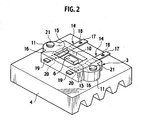
- Fig. 2 is a perspective view showing the fixing structure assembly for a light emitting diode
- Fig. 3 is a exploded perspective view showing the fixing structure assembly for a light emitting diode
- Fig. 4 is a plan view showing a holder housing a light emitting diode in an opening thereof
- Fig. 5 is a bottom view of the holder and the light emitting diode
- Fig. 6 is a cross-section taken along a line VI-VI shown in Fig. 4
- Fig. 7 is a cross-section showing a state in which the light emitting diode is removed from the holder
- Fig. 8 is a cross-section taken along a line VIII-VIII shown in Fig. 4 .
- Fig. 1 shows a basic structure of a lamp unit 1, which is one of the lamp units.
- a light emitting diode 2 is fixed on a top surface of a heat sink 4 with a holder 3 in a state facing upward.
- a reflector 5 On an upper portion of the light emitting diode 2, a reflector 5 having a basically ellipsoidal surface is arranged.
- a light emitting unit 6 of the light emitting diode 2 is focused on a first focal point of the reflector 5, and light L emitted from the light emitting diode 2 is reflected frontward by the reflector 5.
- a projector lens 7 In front, a projector lens 7 is positioned, and the light L reflected by the reflector 5 passes through a second focal point F, and then is lead into the projector lens 7 to be irradiated forward from a vehicle.
- a shade (not shown) is provided near the second focal point F, and the light L lead into the projector lens 7 is irradiated forward in a light distribution pattern corresponding to the shape of the shade.
- the light emitting diode 2 emits white light, and has such a structure that the light emitting unit 6 smaller than a substrate 8 is mounted on the substrate 8 formed in a rectangular shape in which a side in a vehicle width direction (one direction) A is longer than a side in a front-rear direction (the other direction) B.
- the substrate 8 is heat conductive, and has power feeding units 9 of cathode and anode on a top surface on both sides in the vehicle width direction.
- the holder 3 made of resin that is an insulating material is used.
- This holder 3 is basically formed in a rectangular shape, and is a plate-formed member having larger thickness than the substrate 8 of the light emitting diode 2.
- An opening 10 is formed in a central part of the holder 3, and fixing portions 11 in a semicircular shape are formed on both sides in the vehicle width direction in a projecting state.
- a circular fixing hole 12 is formed in each of the fixing portions 11.
- a screw hole 13 corresponding to the fixing hole 12 is formed on the surface of the heat sink 4.
- the opening 10 has a rectangular shape that matches the outline of the substrate 8 of the light emitting diode 2.
- metal wiring bodies 14 in a form of strip-shaped plate are insert-molded in a state of penetrating through the opening 10 in the front-rear direction.
- a half of the metal wiring body 14 on an outer side in the vehicle width direction is covered with a coating 15 that has the same plane as the surface of the holder 3.
- a spring portion 16 that is bent downward in a trapezoidal shape is formed.
- the spring portion 16 is freely deformable inside the opening 10. With an elastic force generated by deformation of the spring portion 16, the power feeding unit 9 of the light emitting diode 2 can be pushed.
- a rear end of the metal wiring body 14 protrudes rearward (externally) from the holder 3 as a connecting terminal 17, and a terminal lock hole 18 is formed at that portion.
- a front end 19 of the metal wiring body 14 protrudes forward a little from the holder 3.
- a positioning hole 20 is formed at a portion near the front end 19 of the metal wiring body 14 in the holder 3. The positioning hole 20 is used when the metal wiring body 14 is set in a mold (not shown) to insert-mold in the holder 3.
- the light emitting diode 2 When the light emitting diode 2 is fixed with the holder 3, first, the light emitting diode 2 is inserted in the opening 10 of the holder 3 from a back side.
- the opening 10 has a shape matching with the substrate 8 of the light emitting diode 2, the light emitting diode 2 is set precisely fitting in the opening 10.
- the light emitting diode 2 is not completely inserted in the opening 10 in this state, and is in a state in which a back surface thereof protrudes a little from a back surface of the holder 3.
- the fixing hole 12 of the holder 3 and the screw hole 13 of the heat sink 4 are put together, and a screw (a fixing means) 21 is inserted from the top and is fastened in the screw hole 13.
- the holder 3 is pushed toward a surface of the heat sink 4 by a fastening force of the screw 21 and is fixed in a state contacting the heat sink 4.
- the spring portion 16 in the opening 10 pushes the power feeding unit 9 of the light emitting diode 2.
- the back surface of the substrate 8 of the light emitting diode 2 is securely brought into close contact with the surface of the heat sink 4, and contact between the spring portion 16 (the metal wiring body 14) and the power feeding unit 9 also becomes firm.
- a terminal-lock terminal 23 that is swaged at an end of a harness 22 is inserted in the connecting terminal 17 protruding rearward from the holder 3.
- a hook 24 as an engaging portion that is formed in the terminal-lock terminal 23, in the terminal lock hole 18, the terminal-lock terminal 23 is prevented from coming apart therefrom.
- the power feeding unit 9 of the light emitting diode 2 is pushed toward the heat sink 4 by the metal wiring body 14 in the opening 10. Therefore, the light emitting diode 2 and the heat sink 4 can be brought into close contact with each other and heat dissipation performance by the heat sink 4 can be improved.
- the entire rear surface of the substrate 8 of the light emitting diode 2 can closely contact with the heat sink 4, and the heat dissipation performance can be sufficiently improved.
- the metal wiring body 14 and the power feeding unit 9 also closely contact with each other. Therefore, performance in feeding power to the light emitting diode 2 is also improved.
- the metal wiring bodies 14 are insert-molded in the holder 3 in a state of penetrating in the front-rear direction respectively, accuracy in attaching the light emitting diode 2 to the heat sink 4 can be improved, and the performance in feeding power to the light emitting diode 2 can be further improved.
- the spring portions 16 are held at both sides in the front-rear direction of the opening 10, thereby improving holding rigidity of the spring portions 16. Therefore, a pushing force of the spring portions 16 applied to the power feeding units 9 can be enhanced according to a fastening force of the screw 21 of the holder 3.
- the power feeding unit 9 of the light emitting diode 2 can be pushed by an elastic force of the spring portion 16. Furthermore, by pushing with the elastic force of the spring portion 16, degradation of the pushing force to the power feeding unit 9 with time can be suppressed. Further, since the spring portion 16 is bent in a trapezoidal shape, an area contacting with the power feeding unit 9 is large, thereby enabling secure supply of power.
- the terminal-lock hole 18 in the connecting terminal 17 of the metal wiring body 14, when the terminal-lock terminal 23 is connected thereto, the hook 24 of the terminal-lock terminal 23 engages with the terminal lock hole 18. Therefore, connection can be achieved easily and the terminal-lock terminal 23 can be prevented from coming apart therefrom.
- the metal wiring body 14 is arranged to protrude from the rear of the holder 3 to form the connecting terminal 17, and the terminal-lock terminal 23 is connected to the connecting terminal 17. Therefore, the fixing structure assembly for the light emitting diode 2 can be made thinner.
- the metal wiring body 14 can be arranged to be exposed in the entire width thereof in the opening 10, or can be arranged such that only a side end portion corresponding to an inner half of the entire width of the metal wiring body 14 is exposed in the opening 10, while embedding an outer half thereof in the holder 3.
Landscapes
- Engineering & Computer Science (AREA)
- General Engineering & Computer Science (AREA)
- Physics & Mathematics (AREA)
- Microelectronics & Electronic Packaging (AREA)
- Optics & Photonics (AREA)
- Arrangement Of Elements, Cooling, Sealing, Or The Like Of Lighting Devices (AREA)
- Led Device Packages (AREA)
- Non-Portable Lighting Devices Or Systems Thereof (AREA)
- Fastening Of Light Sources Or Lamp Holders (AREA)
Applications Claiming Priority (1)
| Application Number | Priority Date | Filing Date | Title |
|---|---|---|---|
| JP2006340337A JP4582087B2 (ja) | 2006-12-18 | 2006-12-18 | 発光ダイオードの固定構造 |
Publications (2)
| Publication Number | Publication Date |
|---|---|
| EP1936263A1 EP1936263A1 (en) | 2008-06-25 |
| EP1936263B1 true EP1936263B1 (en) | 2010-02-17 |
Family
ID=39129815
Family Applications (1)
| Application Number | Title | Priority Date | Filing Date |
|---|---|---|---|
| EP07024240A Expired - Fee Related EP1936263B1 (en) | 2006-12-18 | 2007-12-13 | Fixing structure assembly for light emitting diode |
Country Status (4)
| Country | Link |
|---|---|
| US (1) | US20080144320A1 (ja) |
| EP (1) | EP1936263B1 (ja) |
| JP (1) | JP4582087B2 (ja) |
| DE (1) | DE602007004810D1 (ja) |
Families Citing this family (31)
| Publication number | Priority date | Publication date | Assignee | Title |
|---|---|---|---|---|
| JP4315986B2 (ja) * | 2007-02-08 | 2009-08-19 | 富士通株式会社 | 発光ダイオードを備えた電子機器 |
| JP5073617B2 (ja) * | 2008-08-27 | 2012-11-14 | 株式会社小糸製作所 | 車両用灯具 |
| US20100226139A1 (en) | 2008-12-05 | 2010-09-09 | Permlight Products, Inc. | Led-based light engine |
| JP5479751B2 (ja) * | 2009-02-16 | 2014-04-23 | 株式会社小糸製作所 | 光源モジュール及び車輌用灯具 |
| JP5420344B2 (ja) * | 2009-08-07 | 2014-02-19 | 三洋電機株式会社 | 前照灯 |
| CN102483210B (zh) * | 2009-09-03 | 2015-06-17 | 株式会社小糸制作所 | 发光装置和车辆用前照灯 |
| JP5601512B2 (ja) * | 2009-09-14 | 2014-10-08 | 東芝ライテック株式会社 | 発光装置および照明装置 |
| DE102009055858A1 (de) * | 2009-11-26 | 2011-06-01 | Osram Gesellschaft mit beschränkter Haftung | Leuchtvorrichtung und Verfahren zum Aufbauen einer Leuchtvorrichtung |
| JP5516948B2 (ja) * | 2009-12-25 | 2014-06-11 | カシオ計算機株式会社 | 光源装置及びプロジェクタ |
| JP5779329B2 (ja) * | 2010-01-19 | 2015-09-16 | 市光工業株式会社 | 車両用灯具 |
| JP2011171277A (ja) * | 2010-01-19 | 2011-09-01 | Ichikoh Ind Ltd | 車両用灯具の半導体型光源の光源ユニット、車両用灯具 |
| JP5570331B2 (ja) | 2010-07-12 | 2014-08-13 | 株式会社小糸製作所 | 車両用灯具 |
| DE102010033093A1 (de) * | 2010-08-02 | 2012-02-02 | Osram Opto Semiconductors Gmbh | Optoelektronisches Leuchtmodul und Kfz-Schweinwerfer |
| JP2012038822A (ja) * | 2010-08-04 | 2012-02-23 | Toshiba Lighting & Technology Corp | 発光装置および照明装置 |
| JP5563407B2 (ja) * | 2010-08-26 | 2014-07-30 | パナソニック株式会社 | Led照明ユニット |
| DE102011102550A1 (de) * | 2010-11-18 | 2012-05-24 | Osram Ag | Gehäuse zur Aufnahme mindestens einer Lichtquelle |
| IT1402922B1 (it) * | 2010-12-10 | 2013-09-27 | A A G Stucchi Srl Unico Socio | Porta modulo led. |
| JP5746930B2 (ja) | 2011-08-24 | 2015-07-08 | 株式会社小糸製作所 | 車両用灯具 |
| EP2581656A3 (en) | 2011-10-13 | 2017-07-05 | OSRAM GmbH | Mounting device for lighting sources |
| CN103890487A (zh) * | 2011-10-13 | 2014-06-25 | 欧司朗股份有限公司 | 用于光源的安装装置 |
| WO2013072812A1 (en) * | 2011-11-14 | 2013-05-23 | Koninklijke Philips Electronics N.V. | Led spring clamp & retainer |
| US9170002B2 (en) * | 2012-01-05 | 2015-10-27 | Molex, Llc | Holder and LED module using same |
| DE102012003520B4 (de) * | 2012-02-24 | 2013-12-24 | Bjb Gmbh & Co. Kg | Anschlusselement für eine auf einer Platine angeordnete lichtemittierende Diode (LED) |
| JP5980963B2 (ja) * | 2012-03-02 | 2016-08-31 | モレックス エルエルシー | アレイホルダーおよびアレイホルダーを有するledモジュール |
| AT513328B1 (de) * | 2012-09-04 | 2015-01-15 | Esto Lighting Gmbh | Beleuchtungsvorrichtung |
| JP5548283B2 (ja) * | 2012-10-26 | 2014-07-16 | 株式会社東和化成工業所 | 合成樹脂製ソケット |
| US9985375B2 (en) | 2013-08-09 | 2018-05-29 | Molex, Llc | Holder assembly |
| JP6484967B2 (ja) | 2014-09-12 | 2019-03-20 | パナソニックIpマネジメント株式会社 | ホルダ、照明装置及び照明装置の製造方法 |
| TWI535972B (zh) * | 2014-11-26 | 2016-06-01 | 中強光電股份有限公司 | 車用照明裝置 |
| JP6967961B2 (ja) * | 2017-12-21 | 2021-11-17 | スタンレー電気株式会社 | 車両用灯具用光源ユニット及び車両用灯具 |
| JP2019220424A (ja) * | 2018-06-22 | 2019-12-26 | 東芝ライテック株式会社 | 車両用照明装置、および車両用灯具 |
Family Cites Families (15)
| Publication number | Priority date | Publication date | Assignee | Title |
|---|---|---|---|---|
| JP2567710Y2 (ja) * | 1992-05-21 | 1998-04-02 | スタンレー電気株式会社 | ハイマウントストップランプの給電構造 |
| US6582100B1 (en) * | 2000-08-09 | 2003-06-24 | Relume Corporation | LED mounting system |
| JP2002093206A (ja) * | 2000-09-18 | 2002-03-29 | Stanley Electric Co Ltd | Led信号灯具 |
| JP4095463B2 (ja) * | 2003-02-13 | 2008-06-04 | 松下電器産業株式会社 | Led光源用ソケット |
| US6920046B2 (en) * | 2003-06-25 | 2005-07-19 | Eaton Corporation | Dissipating heat in an array of circuit components |
| JP4258321B2 (ja) * | 2003-08-25 | 2009-04-30 | 市光工業株式会社 | 車両用灯具 |
| JP2005209537A (ja) * | 2004-01-23 | 2005-08-04 | Koito Mfg Co Ltd | 灯具 |
| JP2005217354A (ja) * | 2004-02-02 | 2005-08-11 | Sumitomo Wiring Syst Ltd | 発光素子ユニット |
| JP3851911B2 (ja) * | 2004-05-26 | 2006-11-29 | 株式会社アドバネクス | 発光ダイオードの固定装置及び固定構造 |
| JP4350617B2 (ja) * | 2004-08-24 | 2009-10-21 | 株式会社小糸製作所 | 灯具 |
| JP5103175B2 (ja) * | 2004-11-01 | 2012-12-19 | パナソニック株式会社 | 照明装置及び表示装置 |
| JP2006297707A (ja) * | 2005-04-19 | 2006-11-02 | Koito Mfg Co Ltd | 車輌用灯具の製造方法及び車輌用灯具 |
| US20060262533A1 (en) * | 2005-05-18 | 2006-11-23 | Para Light Electronics Co., Ltd. | Modular light emitting diode |
| US7325949B1 (en) * | 2006-08-17 | 2008-02-05 | Augux Co., Ltd. | Quick assembling structure for LED lamp and heat dissipating module |
| US20080062698A1 (en) * | 2006-09-13 | 2008-03-13 | Yun Tai | LED module |
-
2006
- 2006-12-18 JP JP2006340337A patent/JP4582087B2/ja not_active Expired - Fee Related
-
2007
- 2007-12-12 US US12/000,372 patent/US20080144320A1/en not_active Abandoned
- 2007-12-13 EP EP07024240A patent/EP1936263B1/en not_active Expired - Fee Related
- 2007-12-13 DE DE602007004810T patent/DE602007004810D1/de active Active
Also Published As
| Publication number | Publication date |
|---|---|
| EP1936263A1 (en) | 2008-06-25 |
| JP4582087B2 (ja) | 2010-11-17 |
| US20080144320A1 (en) | 2008-06-19 |
| JP2008153080A (ja) | 2008-07-03 |
| DE602007004810D1 (de) | 2010-04-01 |
Similar Documents
| Publication | Publication Date | Title |
|---|---|---|
| EP1936263B1 (en) | Fixing structure assembly for light emitting diode | |
| JP4702326B2 (ja) | 照明装置用の発光ダイオード固定構造 | |
| JP5746930B2 (ja) | 車両用灯具 | |
| KR100901401B1 (ko) | 광원 모듈 및 차량용 등기구 | |
| KR100872109B1 (ko) | 발광 모듈 및 차량용 등기구 | |
| JP4662361B2 (ja) | 光源モジュール | |
| KR101294657B1 (ko) | 반도체 발광소자 부착용 모듈, 반도체 발광소자 모듈, 반도체 발광소자 조명기구 및 반도체 발광소자 부착용 모듈의 제조방법 | |
| US7901123B2 (en) | Light emitting module and vehicle lamp | |
| JP2007141549A (ja) | 車輌用灯具 | |
| US9206954B2 (en) | Light source unit and vehicular lamp | |
| CN209960391U (zh) | 灯单元 | |
| JP2008186796A (ja) | 発光ダイオードの固定構造 | |
| WO2012120979A1 (ja) | 光源モジュール | |
| JP2007194173A (ja) | 光源モジュール | |
| JP2007018762A (ja) | 発光装置 | |
| JP4835605B2 (ja) | 車両用灯具 | |
| JP6160943B2 (ja) | 照明装置及びホルダ | |
| US10663135B2 (en) | Light module for a vehicle headlight | |
| US20210071851A1 (en) | Light source unit | |
| JP2009199780A (ja) | 車両用灯具 | |
| JP2014197550A (ja) | 光源固定用アタッチメント | |
| JP4760117B2 (ja) | 発光装置及びこの発光装置を備えた照明器具 | |
| JP7121574B2 (ja) | 灯具 | |
| JP7042926B2 (ja) | 車両用灯具 | |
| KR20110015389A (ko) | 차량용 등기구 |
Legal Events
| Date | Code | Title | Description |
|---|---|---|---|
| PUAI | Public reference made under article 153(3) epc to a published international application that has entered the european phase |
Free format text: ORIGINAL CODE: 0009012 |
|
| 17P | Request for examination filed |
Effective date: 20071213 |
|
| AK | Designated contracting states |
Kind code of ref document: A1 Designated state(s): AT BE BG CH CY CZ DE DK EE ES FI FR GB GR HU IE IS IT LI LT LU LV MC MT NL PL PT RO SE SI SK TR |
|
| AX | Request for extension of the european patent |
Extension state: AL BA HR MK RS |
|
| 17Q | First examination report despatched |
Effective date: 20080904 |
|
| AKX | Designation fees paid |
Designated state(s): DE FR GB |
|
| GRAP | Despatch of communication of intention to grant a patent |
Free format text: ORIGINAL CODE: EPIDOSNIGR1 |
|
| RTI1 | Title (correction) |
Free format text: FIXING STRUCTURE ASSEMBLY FOR LIGHT EMITTING DIODE |
|
| GRAS | Grant fee paid |
Free format text: ORIGINAL CODE: EPIDOSNIGR3 |
|
| GRAA | (expected) grant |
Free format text: ORIGINAL CODE: 0009210 |
|
| AK | Designated contracting states |
Kind code of ref document: B1 Designated state(s): DE FR GB |
|
| REG | Reference to a national code |
Ref country code: GB Ref legal event code: FG4D |
|
| REF | Corresponds to: |
Ref document number: 602007004810 Country of ref document: DE Date of ref document: 20100401 Kind code of ref document: P |
|
| PLBE | No opposition filed within time limit |
Free format text: ORIGINAL CODE: 0009261 |
|
| STAA | Information on the status of an ep patent application or granted ep patent |
Free format text: STATUS: NO OPPOSITION FILED WITHIN TIME LIMIT |
|
| 26N | No opposition filed |
Effective date: 20101118 |
|
| PGFP | Annual fee paid to national office [announced via postgrant information from national office to epo] |
Ref country code: DE Payment date: 20101208 Year of fee payment: 4 |
|
| PGFP | Annual fee paid to national office [announced via postgrant information from national office to epo] |
Ref country code: FR Payment date: 20111219 Year of fee payment: 5 |
|
| GBPC | Gb: european patent ceased through non-payment of renewal fee |
Effective date: 20121213 |
|
| REG | Reference to a national code |
Ref country code: FR Ref legal event code: ST Effective date: 20130830 |
|
| REG | Reference to a national code |
Ref country code: DE Ref legal event code: R119 Ref document number: 602007004810 Country of ref document: DE Effective date: 20130702 |
|
| PG25 | Lapsed in a contracting state [announced via postgrant information from national office to epo] |
Ref country code: DE Free format text: LAPSE BECAUSE OF NON-PAYMENT OF DUE FEES Effective date: 20130702 |
|
| PG25 | Lapsed in a contracting state [announced via postgrant information from national office to epo] |
Ref country code: GB Free format text: LAPSE BECAUSE OF NON-PAYMENT OF DUE FEES Effective date: 20121213 Ref country code: FR Free format text: LAPSE BECAUSE OF NON-PAYMENT OF DUE FEES Effective date: 20130102 |