EP1935711A1 - Luftfeder für einen Fahrzeugsitz sowie Fahrzeugsitz mit einer derartigen Luftfeder - Google Patents
Luftfeder für einen Fahrzeugsitz sowie Fahrzeugsitz mit einer derartigen Luftfeder Download PDFInfo
- Publication number
- EP1935711A1 EP1935711A1 EP07123199A EP07123199A EP1935711A1 EP 1935711 A1 EP1935711 A1 EP 1935711A1 EP 07123199 A EP07123199 A EP 07123199A EP 07123199 A EP07123199 A EP 07123199A EP 1935711 A1 EP1935711 A1 EP 1935711A1
- Authority
- EP
- European Patent Office
- Prior art keywords
- air spring
- level control
- air
- height
- control roller
- Prior art date
- Legal status (The legal status is an assumption and is not a legal conclusion. Google has not performed a legal analysis and makes no representation as to the accuracy of the status listed.)
- Granted
Links
- 238000013016 damping Methods 0.000 abstract description 6
- 235000012907 honey Nutrition 0.000 description 6
- 239000000725 suspension Substances 0.000 description 6
- 230000007935 neutral effect Effects 0.000 description 3
- 230000001419 dependent effect Effects 0.000 description 2
- 238000011161 development Methods 0.000 description 2
- 230000018109 developmental process Effects 0.000 description 2
- 230000000712 assembly Effects 0.000 description 1
- 238000000429 assembly Methods 0.000 description 1
- 230000005540 biological transmission Effects 0.000 description 1
- 230000015572 biosynthetic process Effects 0.000 description 1
- 238000001514 detection method Methods 0.000 description 1
- 230000005284 excitation Effects 0.000 description 1
- 230000003993 interaction Effects 0.000 description 1
- 230000002045 lasting effect Effects 0.000 description 1
- 230000010355 oscillation Effects 0.000 description 1
- 230000001105 regulatory effect Effects 0.000 description 1
Images


Classifications
-
- F—MECHANICAL ENGINEERING; LIGHTING; HEATING; WEAPONS; BLASTING
- F16—ENGINEERING ELEMENTS AND UNITS; GENERAL MEASURES FOR PRODUCING AND MAINTAINING EFFECTIVE FUNCTIONING OF MACHINES OR INSTALLATIONS; THERMAL INSULATION IN GENERAL
- F16F—SPRINGS; SHOCK-ABSORBERS; MEANS FOR DAMPING VIBRATION
- F16F9/00—Springs, vibration-dampers, shock-absorbers, or similarly-constructed movement-dampers using a fluid or the equivalent as damping medium
- F16F9/32—Details
- F16F9/43—Filling or drainage arrangements, e.g. for supply of gas
-
- B—PERFORMING OPERATIONS; TRANSPORTING
- B60—VEHICLES IN GENERAL
- B60G—VEHICLE SUSPENSION ARRANGEMENTS
- B60G11/00—Resilient suspensions characterised by arrangement, location or kind of springs
- B60G11/26—Resilient suspensions characterised by arrangement, location or kind of springs having fluid springs only, e.g. hydropneumatic springs
- B60G11/28—Resilient suspensions characterised by arrangement, location or kind of springs having fluid springs only, e.g. hydropneumatic springs characterised by means specially adapted for attaching the spring to axle or sprung part of the vehicle
-
- B—PERFORMING OPERATIONS; TRANSPORTING
- B60—VEHICLES IN GENERAL
- B60G—VEHICLE SUSPENSION ARRANGEMENTS
- B60G17/00—Resilient suspensions having means for adjusting the spring or vibration-damper characteristics, for regulating the distance between a supporting surface and a sprung part of vehicle or for locking suspension during use to meet varying vehicular or surface conditions, e.g. due to speed or load
- B60G17/02—Spring characteristics, e.g. mechanical springs and mechanical adjusting means
- B60G17/04—Spring characteristics, e.g. mechanical springs and mechanical adjusting means fluid spring characteristics
- B60G17/048—Spring characteristics, e.g. mechanical springs and mechanical adjusting means fluid spring characteristics with the regulating means inside the fluid springs
- B60G17/0485—Spring characteristics, e.g. mechanical springs and mechanical adjusting means fluid spring characteristics with the regulating means inside the fluid springs the springs being pneumatic springs with a flexible wall, e.g. with levelling valves
-
- B—PERFORMING OPERATIONS; TRANSPORTING
- B60—VEHICLES IN GENERAL
- B60G—VEHICLE SUSPENSION ARRANGEMENTS
- B60G17/00—Resilient suspensions having means for adjusting the spring or vibration-damper characteristics, for regulating the distance between a supporting surface and a sprung part of vehicle or for locking suspension during use to meet varying vehicular or surface conditions, e.g. due to speed or load
- B60G17/02—Spring characteristics, e.g. mechanical springs and mechanical adjusting means
- B60G17/04—Spring characteristics, e.g. mechanical springs and mechanical adjusting means fluid spring characteristics
- B60G17/052—Pneumatic spring characteristics
- B60G17/0521—Pneumatic spring characteristics the spring having a flexible wall
-
- B—PERFORMING OPERATIONS; TRANSPORTING
- B60—VEHICLES IN GENERAL
- B60G—VEHICLE SUSPENSION ARRANGEMENTS
- B60G17/00—Resilient suspensions having means for adjusting the spring or vibration-damper characteristics, for regulating the distance between a supporting surface and a sprung part of vehicle or for locking suspension during use to meet varying vehicular or surface conditions, e.g. due to speed or load
- B60G17/02—Spring characteristics, e.g. mechanical springs and mechanical adjusting means
- B60G17/04—Spring characteristics, e.g. mechanical springs and mechanical adjusting means fluid spring characteristics
- B60G17/052—Pneumatic spring characteristics
- B60G17/0523—Regulating distributors or valves for pneumatic springs
-
- F—MECHANICAL ENGINEERING; LIGHTING; HEATING; WEAPONS; BLASTING
- F16—ENGINEERING ELEMENTS AND UNITS; GENERAL MEASURES FOR PRODUCING AND MAINTAINING EFFECTIVE FUNCTIONING OF MACHINES OR INSTALLATIONS; THERMAL INSULATION IN GENERAL
- F16F—SPRINGS; SHOCK-ABSORBERS; MEANS FOR DAMPING VIBRATION
- F16F9/00—Springs, vibration-dampers, shock-absorbers, or similarly-constructed movement-dampers using a fluid or the equivalent as damping medium
- F16F9/02—Springs, vibration-dampers, shock-absorbers, or similarly-constructed movement-dampers using a fluid or the equivalent as damping medium using gas only or vacuum
-
- F—MECHANICAL ENGINEERING; LIGHTING; HEATING; WEAPONS; BLASTING
- F16—ENGINEERING ELEMENTS AND UNITS; GENERAL MEASURES FOR PRODUCING AND MAINTAINING EFFECTIVE FUNCTIONING OF MACHINES OR INSTALLATIONS; THERMAL INSULATION IN GENERAL
- F16F—SPRINGS; SHOCK-ABSORBERS; MEANS FOR DAMPING VIBRATION
- F16F9/00—Springs, vibration-dampers, shock-absorbers, or similarly-constructed movement-dampers using a fluid or the equivalent as damping medium
- F16F9/32—Details
- F16F9/44—Means on or in the damper for manual or non-automatic adjustment; such means combined with temperature correction
- F16F9/46—Means on or in the damper for manual or non-automatic adjustment; such means combined with temperature correction allowing control from a distance, i.e. location of means for control input being remote from site of valves, e.g. on damper external wall
- F16F9/461—Means on or in the damper for manual or non-automatic adjustment; such means combined with temperature correction allowing control from a distance, i.e. location of means for control input being remote from site of valves, e.g. on damper external wall characterised by actuation means
- F16F9/462—Rotary actuation means
-
- B—PERFORMING OPERATIONS; TRANSPORTING
- B60—VEHICLES IN GENERAL
- B60G—VEHICLE SUSPENSION ARRANGEMENTS
- B60G2206/00—Indexing codes related to the manufacturing of suspensions: constructional features, the materials used, procedures or tools
- B60G2206/01—Constructional features of suspension elements, e.g. arms, dampers, springs
- B60G2206/40—Constructional features of dampers and/or springs
- B60G2206/42—Springs
- B60G2206/424—Plunger or top retainer construction for bellows or rolling lobe type air springs
Definitions
- the invention relates to a trained according to the preamble of claim 1 air spring for a vehicle seat and vehicle seat with such an air spring.
- Known air spring system of this type usually have a separate from the air spring control (valve control), which serves to control the supply and exhaust air quantity.
- This control serves on the one hand the amount of air in the air spring, to carry the / the corresponding ballast / weight of the seat, and on the other hand, the change in the seat height to adjust these individually body size.
- the air-sprung driver's seat as an assembly air spring, a control unit (level control unit and height control unit), at least one connecting line between the air spring and the control unit and a supply line.
- Exemplary known designs are in DE 40 25 183 C2 , of the DE 35 17 503 C2 , of the DE 35 17 504 C2 or the DE 35 17 505 C2 or the DE 199 02 224 C1 disclosed.
- the invention is an object of the invention to provide a structurally simple and compact, cost-effective way for a vehicle seat suspension with adjustment.
- an air spring for a vehicle seat according to claim 1 is proposed.
- An inventive vehicle seat is the subject of claim 7.
- Preferred developments are the subject of the dependent claims.
- an air spring for a vehicle seat has a plurality of at least one air spring chamber limiting air spring components.
- the air spring forms a supply air connection and an exhaust air connection.
- the air spring for height and / or level control of the vehicle seat on a valve device which is integrated in the air spring or in at least one air spring component.
- the air spring component in question is preferably a piston lower part or a piston upper part or a cylinder lower part or a cylinder upper part of the air spring.
- the vehicle seat can, for example, have a scissors system or scissor-type frame, which can be designed, for example, in such a way as is known in the art DE 40 25 183 C1 or the DE 35 17 504 C2 or the DE 35 17 505 C2 or the DE 199 02 224 C1 is disclosed. It is expressly referred to with respect to preferred embodiments of the present disclosure, the relevant disclosure of which are hereby incorporated by reference into the subject of the present disclosure.
- the vehicle seat may be, for example, a tractor seat, a truck or a commercial vehicle seat or a seat of a bus, in each case in particular a driver's seat.
- this module has a level control roller, a level control lever, a height adjustment control roller and a quick lowering or consists thereof.
- the level control via a piston in the lower part and / or in the upper and / or upper cylinder and / or cylinder base mounted control roller, control disk or the like, which releases the supply air or exhaust air ducts in an advantageous configuration during rotation.
- a level control lever can be provided.
- Such a level control lever can be the connection of a scissor system with the level control roller. It can be provided that the transmission of the introduction to the level control roller by the control lever with a determined by an inertia element maximum speed (frequency), which is far below the usual vibration frequencies.
- a damping element or a honey engine may be provided.
- a damping element which determines the maximum rotational speed of the control roller, a frequency-dependent level correction is possible, whereby an "unnecessary” readjustment of the level is suppressed.
- the inertia (switching frequency) of such a damping element is conveniently below the typical operating frequencies of the system (e.g., 0.5 Hz).
- one or the damping element with longer lasting symmetry deviations to the zero line (level) allows a slow tracking of the control roller and hereby releases the inlet and outlet cross sections for correcting the level.
- control roller after a longer or permanent deviation from the zero line (level) lags in the maximum speed and the control bores for supply or exhaust air releases (driver change, weight adjustment).
- a HV-control roller for changing the seat height or a HV-control roller is rotated in relation or relative to or to a level roller, which leads to a supposed (desired) malposition of the level roller or can lead thereafter, for example, can be corrected so that a desired height adjustment is effected or is the result.
- the exact height correction takes place only in the dynamic range (eg permanent overshoot of the position in one direction).
- the control of the HV control roller can be done for example via a Bowden cable or a differently designed control element; the provision is preferably made via a tension spring.
- a rapid lowering is made possible.
- the rapid lowering (SA) takes place in an advantageous design via a second lever (button), which operates the HV Bowden cable via a freewheel.
- HV roller HV at the bottom
- a deviation from too high is specified, the correction takes place with maximum flow cross-section downwards; It can be provided that when releasing the quick lowering the level detection (also) takes place as quickly as possible.
- the correction speed is slowed down due to the changing cross section when approaching the HV position (level).
- the quick lowering could also be done via the HV area code, but the previous HV position would have to be re-dialed.
- Fig. 1 shows a first exemplary air spring 1 according to the invention for the suspension and adjustment, in particular height and / or level control, air-suspended vehicle seats in a partial, schematic exploded view, the design according to Fig. 1 has an integrated freewheel.
- Fig. 2 shows a second exemplary inventive air spring 1 for the suspension and adjustment, in particular height and / or level control, air-suspended vehicle seats in partial, schematic exploded view, wherein the adjustment according to Fig. 2 has an external freewheel.
- FIGS. 1 and 2 shown air springs 1 thus differ in particular in that in the in Fig. 1 shown air spring 1, a driver 10 and a valve lever 12 and a torsion spring, not shown, is provided, while instead according to the design Fig. 2 a drive wheel 14 is provided.
- FIGS. 1 and 2 shown embodiments are not substantially different from each other, so that the description is done so far in common for both designs.
- air springs 1 have a plurality of air spring components for limiting an air-filled air spring chamber 16, of which an air spring member 18 which is designed as a piston lower part or cylinder base, in the FIGS. 1 and 2 is shown.
- the air spring component 18 which as an item in different views in the FIGS. 3 to 6 is shown, for the height and / or level control of the vehicle seat on a supply air port 20 and an exhaust port 22.
- the supply air connection 20 extends parallel to this exhaust air connection 22.
- Transversely to this supply air connection 20 and this exhaust air connection 22, the air spring component 18 has a passage 24 into which the supply air connection 20 and the exhaust air connection 22 open.
- HV module or the height control roller 26 In the assembled state extending through or into the passage 24 an HV module or a height control roller 26 and a level control or level control roller 28.
- the HV module or the height control roller 26 is designed as a hollow cylinder, so that in the HV module or in the height control roller 26, a passageway is formed, in which the level control or level control roller 28 is rotatably received.
- the height control roller or the HV module 26 is in different views as a single part in the FIGS. 7 to 12 and the level control roller 28 is shown in various views in FIGS FIGS. 13 to 24 shown.
- two through holes 32, 34 are provided, which are also referred to as a first through hole 32 and second through hole 34 for simplified reference and from the interior of the air spring chamber 16 provided for receiving the spring-air volume to the passage 24 extend.
- the first passage opening 32 is provided for the outflow of air from the air spring chamber 16 and the second passage opening 34 for the filling or inflow of air into the air spring chamber 16th
- the HV module or the height control roller 26 has in its outer jacket on a first annular channel 36 for exhaust air and a second annular channel 38 for supply air. At least one third through-opening 40 is provided in the bottom of the first annular channel 36, and at least one fourth through-opening 42 is provided in the bottom of the second annular channel 38.
- Axially offset (relative to the axial direction of the HV module or the height control roller 26 or the level control or the level control roller 28) to the first annular channel 36 with the third through hole 40 extends radially through the HV module or the height control roller 26 a fifth Through opening 44, which extends, for example - as here radially outside - in the axial direction and in the circumferential direction (eg over ⁇ 27.5 °).
- This fifth passage opening 44 is provided as the third passage 40 for exhaust air.
- Axially offset (relative to the axial direction of the HV module or the height control roller 26 or the level control or the level control roller 28) to the second annular channel 38 with the fourth passage opening 42 extends radially through the HV module and the height control roller 26, a sixth Through opening 46, which extends, for example - as here radially outside - in the axial direction and in the circumferential direction (eg over ⁇ 27.5 °).
- This sixth passage opening 46 is provided as the fourth passage opening 42 for supply air.
- the level control or level control roller 28 is hollow or hollow cylindrical.
- the level control or level control roller 28 has in its outer jacket a third annular channel 48 for exhaust air and - in particular axially offset thereto - a fourth annular channel 50 for supply air.
- a seventh through-opening 52 extends into the radially interior of the level control or level control roller 28 and from the fourth annular channel 50, an eighth through-hole 54 extends into the radial interior of the level control or level control roller 28th
- Axially offset (relative to the axial direction of the HV module or the height control roller 26 or the level control or the level control roller 28) to the third annular channel 48 with the seventh through hole 52 extends radially through the level control or level control roller 28, a ninth through-hole 56, which expands, for example - as here radially outside - in the axial direction and in the circumferential direction.
- This ninth through-hole 56 is provided as the seventh through-hole 52 for exhaust air.
- Axially offset (relative to the axial direction of the HV module or the height control roller 26 or the level control or the level control roller 28) to the fourth annular channel 50 with the eighth through hole 54 extends radially through the level control or level control roller 28 a tenth passage opening 58, which expands, for example - as here radially outside - in the axial direction and in the circumferential direction.
- This tenth passage opening 58 is provided as the eighth passage opening 54 for supply air.
- the HV module or the height control roller 26 can be rotated relative to the air spring component or piston lower part or lower cylinder part 18 and relative to the level control or level control roller 28.
- the level control or level control roller 28 can be rotated relative to the air spring component or lower piston part or lower part 18 of the cylinder.
- the first passage opening 32, the fifth passage opening 44 and the ninth passage opening 56 axially at a height, so that these - at corresponding rotational positions of the HV module or the height control roller 26 and the level control or level control roller 28 - are fluidly connected.
- the first annular channel 36, the third passage opening 40, the third annular channel 48 and the seventh passage opening 52 axially at a height, so that they are fluidly connected.
- the second passage opening 34, the sixth passage opening 46 and the tenth passage opening 58 axially at a height, so that these - at corresponding rotational positions of the HV module or the height control roller 26 and the level control or level control roller 28 - are fluidly connected.
- the second annular channel 38, the fourth through-hole 42, the fourth annular channel 50 and the eighth through-hole 54 axially at a height, so that they are fluidly connected.
- the supply air connection 20 opens into the second annular channel 38.
- the exhaust air connection 22 opens into the first annular channel 36.
- the seventh passage opening 52 and the ninth passage opening 56 are flow-connected via an exhaust air chamber 60. Furthermore, the eighth passage opening 54 and the tenth passage opening 58 are flow-connected via an inlet air chamber 62 in the interior of the level control or the level control roller 28.
- a HV lever 66 is given.
- This HV lever 66 is rotatably connected to the level control or level control roller 28.
- the HV lever 66 can be actuated in a rotating or pivoting manner, for example by means of a Bowden cable.
- the FIGS. 25 to 29 branches various views of the HV lever.
- a driver 70 and a valve lever 72 is also given.
- the driver 70 is inserted in the valve lever 12 with its central projection 74.
- the driver 70 further forms an eccentrically arranged axial projection 76 for the interaction with a leg spring, not shown, and a below-mentioned web 78.
- the valve lever has in its outer shell a circumferentially extending slot 80 which is interrupted by the already mentioned web 78.
- the leg spring (not shown) extends around the central projection 74, with its legs engaging behind both the axial projection 76 and the web 78 in such a way that the spring is loaded at a torque for rotating the valve lever 72 relative to the driver 70, and although independent of the direction of rotation of the torque.
- FIGS. 33 to 37 Various views of the driver 70 are in the FIGS. 33 to 37 shown.
- Various views of the valve lever 72 are in the FIGS. 38 to 43 shown.
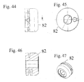
- a drive wheel 82 is provided. Instead of the spring in Fig. 1 not shown, but there is given in the design according to Fig. 2 be given a Bowden cable, which engages in the drive wheel.
- Various views of the drive wheel 82 are in the FIGS. 44 to 47 shown.
- It is formed in particular by a valve whose positions are adjustable in particular by turning the HV module or the height control roller 26 and the level control or level control roller 28.
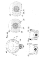
- FIG. 50 to 56 show different positions of the design according to Fig. 1 respectively.
- Fig. 2 showing a sectional view and an enlarged detail of this respective sectional view.
- Fig. 50 shows the position "HV down”; 51 shows the position "HV middle”; Fig. 52 shows the position "HV top”.
- Fig. 53 shows the position "level oK"(closed); Fig. 54 shows the position "in order / HV center”; Fig. 55 shows the position "level too high” (exhaust air open); and Fig. 56 shows the position "level too low” (supply air open).
- Fig. 57 a) - c) shows a further view of the design according to the invention with two sections illustrating a position of the design according to the invention.
- Fig. 61 a) - e) and Fig. 62 a) - e) show different positions of the design according to Fig. 1 or according to Fig. 2 ,
- Fig. 58 a) - e) shows a position in which the height adjustment has its position "center", the level is neutral, and therefore the supply air is closed and the exhaust air is closed.
- Fig. 59 a) - e) shows a position in which the height adjustment has its position "center", the level is too low, and consequently the supply air is opened and the exhaust air is closed.
- Fig. 60 a) - e) shows a position in which the height adjustment has its position "center", the level is too high, and therefore the supply air is closed and the exhaust air is opened.
- Fig. 61 a) - e) shows a position in which the height adjustment has its position "down", the level is neutral, and therefore the supply air is closed and the exhaust air is closed.
- Fig. 62 a) - e) shows a position in which the height adjustment has its position "up", the level is neutral, and therefore the supply air is closed and the exhaust air is closed.
- the freewheels can also be designed by means of tension springs.
- the invention reduces the aforementioned (there four) assemblies on two modules, namely the air spring with integrated control unit (level control unit and height control unit) and the supply line (network).
- the complete control unit consisting of height adjustment and level control is integrated in the air spring piston.
- the operation of the level control unit is similar to other known systems, by a direct connection, such as. Connecting rod, rack o. ⁇ . The rocker / scissors.
- the excitation of the control is done by the vertical movement of the suspension (the guide system) in the driver's seat, in this case shown as an X-shaped scissors.
- the height adjustment of the suspension system is about the rotation of the height control roller, which with a Bowden o. ⁇ . a handwheel is connected, made.
- the level control roller is additionally equipped with a frequency controller to prevent permanent regulation by supplying and removing supply air from a frequency of approx.> 0.5 Hz.
Abstract
Description
- Die Erfindung betrifft eine gemäß dem Oberbegriff des Patentanspruchs 1 ausgebildete Luftfeder für einen Fahrzeugsitz sowie Fahrzeugsitz mit einer derartigen Luftfeder.
- Bekannte Luftfedersystem dieser Art haben üblicherweise ein von der Luftfeder getrenntes Steuerelement (Ventilsteuerung), welches der Regelung der Zu- bzw. Abluftmenge dient. Diese Steuerung dient zum einen der Luftmenge in der Luftfeder, um die/das entsprechende Auflast/Gewicht des Sitzes zu tragen, und zum anderen der Veränderung der Sitzhöhe, um diese individuell der Körpergröße anpassen zu können. Bei den bekannten Gestaltungen dieser Art erfordert der luftgefederte Fahrersitz als Baugruppe eine Luftfeder, eine Steuereinheit (Niveau-Steuereinheit und Höhen-Steuereinheit), zumindest eine Verbindungsleitung zwischen der Luftfeder und der Steuereinheit sowie eine Versorgungsleitung.
- Beispielhafte bekannte Gestaltungen sind in der
DE 40 25 183 C2 , derDE 35 17 503 C2 , derDE 35 17 504 C2 oder derDE 35 17 505 C2 oder derDE 199 02 224 C1 offenbart. - Der Erfindung liegt nun die Aufgabe zugrunde, eine baulich einfache und kompakte, kostengünstige Möglichkeit für eine Fahrzeugsitzfederung mit Verstellmöglichkeit zu schaffen.
- Erfindungsgemäß wird eine Luftfeder für einen Fahrzeugsitz gemäß Patentanspruch 1 vorgeschlagen. Ein erfindungsgemäßer Fahrzeugsitz ist Gegenstand des Patentanspruchs 7. Bevorzugte Weiterbildungen sind Gegenstand der Unteransprüche.
- Es wird insbesondere eine Luftfeder für einen Fahrzeugsitz vorgeschlagen. Die Luftfeder weist mehrere wenigstens eine Luftfederkammer begrenzende Luftfeder-Bauteile auf. Zur Höhen- und/oder Niveausteuerung des Fahrzeugsitzes bildet die Luftfeder einen Zuluftanschluss und einen Abluftanschluss aus.
- Ferner weist die Luftfeder zur Höhen- und/oder Niveausteuerung des Fahrzeugsitzes eine Ventileinrichtung auf, die in der Luftfeder bzw. in wenigstens einem Luftfeder-Bauteil integriert ist. Das betreffende Luftfeder-Bauteil ist vorzugsweise ein Kolbenunterteil oder ein Kolbenoberteil oder ein Zylinderunterteil oder ein Zylinderoberteil der Luftfeder.
- Ferner wird ein Fahrzeugsitz mit einer derartigen Luftfeder vorgeschlagen. Der Fahrzeugsitz kann beispielsweise ein Scherensystem bzw. Scherengestell aufweisen, das beispielsweise derart ausgestaltet sein kann, wie es in der
DE 40 25 183 C1 oder derDE 35 17 504 C2 oder derDE 35 17 505 C2 oder derDE 199 02 224 C1 offenbart ist. Darauf wird ausdrücklich im Hinblick auf bevorzugte Weiterbildungen der vorliegenden Offenbarung Bezug genommen, wobei die entsprechenden Offenbarungsstellen hiermit durch Bezugnahme zum Gegenstand der vorliegenden Offenbarung gemacht werden. Der Fahrzeugsitz kann beispielsweise ein Traktorsitz, ein Lastkraftwagen- oder ein NKW-Sitz oder ein Sitz eines Busses, und zwar jeweils insbesondere ein Fahrersitz, sein. - Es ist insbesondere vorgesehen, dass sämtliche Funktionen zur Regelung der Federung im Kolbenunterteil bzw. im Kolbenoberteil oder im Zylinderoberteil bzw. Zylinderunterteil integriert sind. Dies ist insbesondere derart, dass ein Modul gebildet wird.
- Dabei kann vorgesehen sein, dass dieses Modul eine Niveausteuerwalze, einen Niveausteuerhebel, eine Höhenverstell-Steuerwalze sowie eine Schnellabsenkung aufweist oder hieraus besteht.
- Es kann vorgesehen sein, dass die Niveauregulierung über eine im Kolbenunterteil und/oder im Kolbenoberteil bzw. im Zylinderoberteil und/oder Zylinderunterteil angebrachte Steuerwalze, Steuerscheibe oder dergleichen erfolgt, die in vorteilhafter Gestaltung bei Verdrehung die Zuluft- oder Abluftkanäle freigibt bzw. schließt.
- Ferner kann ein Niveausteuerhebel vorgesehen sein. Ein solcher Niveausteuerhebel kann dabei die Verbindung eines Scherensystems mit der Niveausteuerwalze sein. Es kann vorgesehen sein, dass die Übertragung der Einleitung auf die Niveausteuerwalze durch den Steuerhebel mit einer durch ein Trägheitselement bestimmten Maximalgeschwindigkeit (Frequenz) erfolgt, welche weit unter den üblichen Schwingungsfrequenzen liegt.
- Ferner kann ein Dämpfungselement bzw. ein Honigmotor vorgesehen sein. Durch ein Dämpfungselement ("Honigmotor"), welches die maximale Verdrehgeschwindigkeit der Steuerwalze bestimmt, wird eine frequenzabhängige Niveaukorrektur ermöglicht, wodurch eine "nicht notwendige" Nachregelung des Niveaus unterbunden wird. Die Trägheit (Schaltfrequenz) eines solchen Dämpfungselements liegt in zweckmäßiger Gestaltung unterhalb der typischen Betriebsfrequenzen des Systems (z.B. 0,5 Hz).
- In besonders zweckmäßiger Ausgestaltung wird bei gleichmäßigen Schwingungseinleitungen (z.B. 0,5 Hz) um den Niveaubereich aufgrund des in vorteilhafter Weiterbildung vorgesehenen gefederten Freilaufs ein Nachregeln (Zu- / Abluft) unterbunden, d.h. das Niveausteuersystem bleibt geschlossen, die Bewegung der Schwinge setzt sich allein im Freilauf um.
- Es kann vorgesehen sein, dass ein bzw. das Dämpfungselement bei länger anhaltenden Symmetrieabweichungen zur Nulllinie (Niveau) ein langsames Nachlaufen der Steuerwalze zulässt und hiermit die Einlass- bzw. Auslassquerschnitte zur Korrektur des Niveaus freigibt.
- Es kann vorgesehen sein, dass die Steuerwalze bei längerer oder dauerhafter Abweichung von der Nulllinie (Niveau) in der maximalen Geschwindigkeit nachläuft und die Steuerbohrungen für Zu- oder Abluft freigibt (Fahrerwechsel, Gewichtsanpassung).
- Ferner kann vorgesehen sein, dass die Zu- bzw. Abluftmenge hierbei über einen sich verändernden Querschnitt in der Niveauwalze der Fehlstellung angepasst wird (z.B. große Abweichung = großer Querschnitt).
- In vorteilhafter Gestaltung ist vorgesehen, dass zur Veränderung der Sitzhöhe die bzw. eine HV-Steuerwalze in Relation bzw. relativ zur bzw. zu einer Niveauwalze verdreht wird, was zu einer vermeintlichen (gewünschten) Fehlstellung der Niveauwalze führt bzw. führen kann, die danach beispielsweise derart korrigiert werden kann, dass eine gewünschte Höhenanpassung bewirkt wird bzw. die Folge ist. In vorteilhafter Gestaltung erfolgt die genaue Höhenkorrektur erst im dynamischen Bereich (z.B. permanente Überschreitung der Position in einer Richtung).
- Die Ansteuerung der HV-Steuerwalze kann beispielsweise über einen Bowdenzug oder ein anders gestaltetes Ansteuerelement erfolgen; die Rückstellung erfolgt vorzugsweise über eine Zugfeder.
- In vorteilhafter Gestaltung wird eine Schnellabsenkung ermöglicht. Die Schnellabsenkung (SA) erfolgt in vorteilhafter Gestaltung über einen zweiten Hebel (Taste), welche den HV-Bowdenzug über einen Freilauf bedient. Durch Verdrehen der HV-Walze (HV maximal unten) wird eine Abweichung von zu weit oben vorgegeben, die Korrektur erfolgt mit maximalem Strömungsquerschnitt nach unten; es kann vorgesehen sein, dass beim Lösen der Schnellabsenkung die Niveaufindung (ebenfalls) schnellstmöglich erfolgt. Insbesondere kann vorgesehen sein, dass die Korrekturgeschwindigkeit aufgrund des sich ändernden Querschnitts bei Annäherung an die HV-Position (Niveau) verlangsamt wird.
- Die Schnellabsenkung könnte auch ebenso über die HV-Vorwahl erfolgen, wobei allerdings die vorherige HV-Position neu angewählt werden müsste.
- Anhand der Figuren sollen im Folgenden Ausführungsbeispiele der Erfindung näher erläutert werden. Dabei zeigen:
- Fig. 1
- eine erste beispielhafte erfindungsgemäße Ausführungsform in teilweiser, schematischer Explosionsansicht;
- Fig. 2
- eine zweite beispielhafte erfindungsgemäße Ausführungsform in teilweiser, schematischer Explosionsansicht;
- Fig. 3 - Fig. 6
- verschiedene Ansichten des Kolbenunterteils bzw. Zylinderunterteils der in den
Fig. 1 und2 gezeigten Gestaltungen; - Fig. 7 - Fig. 12
- verschiedene Ansichten der Höhensteuerwalze bzw. des HV-Moduls der in den
Fig. 1 und2 gezeigten Gestaltungen; - Fig. 13 - Fig. 24
- verschiedene Ansichten der Niveausteuerwalze bzw. Niveausteuerung der in den
Fig. 1 und2 gezeigten Gestaltungen; - Fig. 25 - Fig. 29
- verschiedene Ansichten des HV-Hebels der in den
Fig. 1 und2 gezeigten Gestaltungen; - Fig. 30 - Fig. 32
- verschiedene Ansichten des Dämpfers bzw. Frequenzreglers bzw. "Honigmotors" der in den
Fig. 1 und2 gezeigten Gestaltungen; - Fig. 33 - Fig. 37
- verschiedene Ansichten des Mitnehmers der in
Fig. 1 gezeigten Gestaltung; - Fig. 38 - Fig. 43
- verschiedene Ansichten des Ventil-Hebels der in
Fig. 1 gezeigten Gestaltung; - Fig. 44 - Fig. 47
- verschiedene Ansichten des Antriebsrades der in
Fig. 2 gezeigten Gestaltung; - Fig. 48 - Fig. 49
- 3-D-Ansichten der Gestaltung gemäß
Fig. 1 bzw. gemäßFig. 2 ; - Fig. 50 - Fig. 56
- verschiedene Stellungen der Gestaltung gemäß
Fig. 1 bzw. gemäßFig. 2 in jeweils teilgeschnittener Ansicht und als vergrößerter Ausschnitt aus der jeweiligen teilgeschnittenen Ansicht; - Fig. 57 a) - c)
- eine weitere Ansicht der erfindungsgemäßen Gestaltung mit zwei Schnitten die eine Stellung der erfindungsgemäßen Gestaltung verdeutlichen; und
- Fig. 58 a) - e),
- Fig. 59 a) - e),
- Fig. 60 a) - e),
- Fig. 61 a) - e) u.
- Fig. 62 a) - e)
- verschiedene Stellungen der Gestaltung gemäß
Fig. 1 bzw. gemäßFig. 2 , und zwar in jeweils fünf Ansichten. -
Fig. 1 zeigt eine erste beispielhafte erfindungsgemäße Luftfeder 1 für die Federung sowie Verstellung, insbesondere Höhen- und/oder Niveausteuerung, von luftgefederten Fahrzeugsitzen in teilweiser, schematischer Explosionsansicht, wobei die Gestaltung gemäßFig. 1 einen integrierten Freilauf aufweist. -
Fig. 2 zeigt eine zweite beispielhafte erfindungsgemäße Luftfeder 1 für die Federung sowie Verstellung, insbesondere Höhen- und/oder Niveausteuerung, von luftgefederten Fahrzeugsitzen in teilweiser, schematischer Explosionsansicht, wobei die Verstellvorrichtung gemäßFig. 2 einen externen Freilauf aufweist. - Die in den
Figuren 1 und2 gezeigten Luftfedern 1 unterscheiden sich also insbesondere dadurch, dass bei der inFig. 1 gezeigten Luftfeder 1 ein Mitnehmer 10 und ein Ventilhebel 12 sowie eine nicht dargestellte Drehfeder vorgesehen ist, während stattdessen bei der Gestaltung gemäßFig. 2 ein Antriebsrad 14 vorgesehen ist. - Ungeachtet dessen unterscheiden sich die in den
Figuren 1 und2 gezeigten Gestaltungen im Wesentlichen nicht voneinander, so dass die Beschreibung insofern für beide Gestaltungen gemeinsam erfolgt. - Die in den
Figuren 1 und2 gezeigten Luftfedern 1 weisen mehrere Luftfeder-Bauteile für die Begrenzung einer mit Luft befüllbaren Luftfederkammer 16 auf, von denen ein Luftfeder-Bauteil 18, das als Kolbenunterteil bzw. Zylinderunterteil gestaltet ist, in denFiguren 1 und2 gezeigt ist. - Das Luftfeder-Bauteil 18, das als Einzelteil in verschiedenen Ansichten in den
Figuren 3 bis 6 gezeigt ist, weist für die Höhen- und/oder Niveausteuerung des Fahrzeugsitzes einen Zuluftanschluss 20 und einen Abluftanschluss 22 auf. Der Zuluftanschluss 20 erstreckt sich parallel zu diesem Abluftanschluss 22. Quer zu diesem Zuluftanschluss 20 und diesem Abluftanschluss 22 weist das Luftfeder-Bauteil 18 einen Durchgangskanal 24 auf, in den der Zuluftanschluss 20 sowie der Abluftanschluss 22 münden. - Im montierten Zustand erstrecken sich durch bzw. in den Durchgangskanal 24 ein HV-Modul bzw. eine Höhensteuerwalze 26 sowie eine Niveausteuerung bzw. Niveausteuerwalze 28. Das HV-Modul bzw. die Höhensteuerwalze 26 ist hohlzylindrisch gestaltet, so dass in dem HV-Modul bzw. in der Höhensteuerwalze 26 ein Durchgangskanal ausgebildet wird, in welchem die Niveausteuerung bzw. Niveausteuerwalze 28 drehbar aufgenommen ist.
- Die Höhensteuerwalze bzw. das HV-Modul 26 ist in verschiedenen Ansichten als Einzelteil in den
Figuren 7 bis 12 gezeigt, und die Niveausteuerwalze bzw. Niveausteuerung 28 ist in verschieden Ansichten in denFiguren 13 bis 24 gezeigt. - Im Boden 30 des Luftfeder-Bauteils bzw. Kolbenunterteils bzw. Zylinderunterteils 18 sind - bezüglich der Längsachse des Durchgangskanals 24 - axial versetzt zwei Durchgangsöffnungen 32, 34 vorgesehen, die zur vereinfachten Bezugnahme auch als erste Durchgangsöffnung 32 bzw. zweite Durchgangsöffnung 34 bezeichnet werden und sich vom Innenraum der zur Aufnahme des Feder-Luftvolumens vorgesehen Luftfederkammer 16 zum Durchgangskanal 24 erstrecken.
- Die erste Durchgangsöffnung 32 ist für das Abströmen von Luft aus der Luftfederkammer 16 vorgesehen und die zweite Durchgangsöffnung 34 für das Befüllen bzw. Zuströmen von Luft in die Luftfederkammer 16.
- Das HV-Modul bzw. die Höhensteuerwalze 26 weist in Ihrem Außenmantel einen ersten Ringkanal 36 für Abluft sowie einen zweiten Ringkanal 38 für Zuluft auf. Im Boden des ersten Ringkanals 36 ist wenigstens eine dritte Durchgangsöffnung 40 vorgesehen, und im Boden des zweiten Ringkanals 38 ist wenigstens eine vierte Durchgangsöffnung 42 vorgesehen.
- Axial versetzt (bezogen auf die Axialrichtung des HV-Moduls bzw. der Höhensteuerwalze 26 bzw. der Niveausteuerung bzw. der Niveausteuerwalze 28) zum ersten Ringkanal 36 mit der dritten Durchgangsöffnung 40 erstreckt sich radial durch das HV-Modul bzw. die Höhensteuerwalze 26 eine fünfte Durchgangsöffnung 44, die sich beispielsweise - wie hier radial außen - in Axialrichtung und in Umfangsrichtung (z.B. über ±27,5°) erweitert. Diese fünfte Durchgangsöffnung 44 ist wie die dritte Durchgangsöffnung 40 für Abluft vorgesehen.
- Axial versetzt (bezogen auf die Axialrichtung des HV-Moduls bzw. der Höhensteuerwalze 26 bzw. der Niveausteuerung bzw. der Niveausteuerwalze 28) zum zweiten Ringkanal 38 mit der vierten Durchgangsöffnung 42 erstreckt sich radial durch das HV-Modul bzw. die Höhensteuerwalze 26 eine sechste Durchgangsöffnung 46, die sich beispielsweise - wie hier radial außen - in Axialrichtung und in Umfangsrichtung (z.B. über ± 27,5°) erweitert. Diese sechste Durchgangsöffnung 46 ist wie die vierte Durchgangsöffnung 42 für Zuluft vorgesehen.
- Die Niveausteuerung bzw. Niveausteuerwalze 28 ist hohl bzw. hohlzylindrisch gestaltet. Die Niveausteuerung bzw. Niveausteuerwalze 28 weist in ihrem Außenmantel einen dritten Ringkanal 48 für Abluft sowie - insbesondere axial versetzt hierzu - einen vierten Ringkanal 50 für Zuluft auf. Vom dritten Ringkanal 48 erstreckt sich eine siebte Durchgangsöffnung 52 in das radial Innere der Niveausteuerung bzw. Niveausteuerwalze 28 und vom vierten Ringkanal 50 erstreckt sich eine achte Durchgangsöffnung 54 in das radial Innere der Niveausteuerung bzw. Niveausteuerwalze 28.
- Axial versetzt (bezogen auf die Axialrichtung des HV-Moduls bzw. der Höhensteuerwalze 26 bzw. der Niveausteuerung bzw. der Niveausteuerwalze 28) zum dritten Ringkanal 48 mit der siebten Durchgangsöffnung 52 erstreckt sich radial durch die Niveausteuerung bzw. Niveausteuerwalze 28 eine neunte Durchgangsöffnung 56, die sich beispielsweise - wie hier radial außen - in Axialrichtung und in Umfangsrichtung erweitert. Diese neunte Durchgangsöffnung 56 ist wie die siebte Durchgangsöffnung 52 für Abluft vorgesehen.
- Axial versetzt (bezogen auf die Axialrichtung des HV-Moduls bzw. der Höhensteuerwalze 26 bzw. der Niveausteuerung bzw. der Niveausteuerwalze 28) zum vierten Ringkanal 50 mit der achten Durchgangsöffnung 54 erstreckt sich radial durch die Niveausteuerung bzw. Niveausteuerwalze 28 eine zehnte Durchgangsöffnung 58, die sich beispielsweise - wie hier radial außen - in Axialrichtung und in Umfangsrichtung erweitert. Diese zehnte Durchgangsöffnung 58 ist wie die achte Durchgangsöffnung 54 für Zuluft vorgesehen.
- Das HV-Modul bzw. die Höhensteuerwalze 26 kann relativ zum Luftfeder-Bauteil bzw. Kolbenunterteil bzw. Zylinderunterteil 18 und relativ zur Niveausteuerung bzw. Niveausteuerwalze 28 verdreht werden. Die Niveausteuerung bzw. Niveausteuerwalze 28 kann relativ zum Luftfeder-Bauteil bzw. Kolbenunterteil bzw. Zylinderunterteil 18 verdreht werden.
- Bezogen auf die Axialrichtung des HV-Moduls bzw. der Höhensteuerwalze 26 bzw. der Niveausteuerung bzw. der Niveausteuerwalze 28 sind die erste Durchgangsöffnung 32, die fünfte Durchgangsöffnung 44 und die neunte Durchgangsöffnung 56 axial auf einer Höhe, so dass diese - bei entsprechenden Drehstellungen des HV-Moduls bzw. der Höhensteuerwalze 26 und der Niveausteuerung bzw. Niveausteuerwalze 28 - strömungsverbunden sind.
- Bezogen auf die Axialrichtung des HV-Moduls bzw. der Höhensteuerwalze 26 bzw. der Niveausteuerung bzw. der Niveausteuerwalze 28 sind der erster Ringkanal 36, die dritte Durchgangsöffnung 40, der dritte Ringkanal 48 und die siebte Durchgangsöffnung 52 axial auf einer Höhe, so dass diese strömungsverbunden sind.
- Bezogen auf die Axialrichtung des HV-Moduls bzw. der Höhensteuerwalze 26 bzw. der Niveausteuerung bzw. der Niveausteuerwalze 28 sind die zweite Durchgangsöffnung 34, die sechste Durchgangsöffnung 46 und die zehnte Durchgangsöffnung 58 axial auf einer Höhe, so dass diese - bei entsprechenden Drehstellungen des HV-Moduls bzw. der Höhensteuerwalze 26 und der Niveausteuerung bzw. Niveausteuerwalze 28 - strömungsverbunden sind.
- Bezogen auf die Axialrichtung des HV-Moduls bzw. der Höhensteuerwalze 26 bzw. der Niveausteuerung bzw. der Niveausteuerwalze 28 sind der zweite Ringkanal 38, die vierte Durchgangsöffnung 42, der vierte Ringkanal 50 sowie die achte Durchgangsöffnung 54 axial auf einer Höhe, so dass diese strömungsverbunden sind.
- Der Zuluftanschluss 20 mündet in den zweiten Ringkanal 38. Der Abluftanschluss 22 mündet in den ersten Ringkanal 36.
- Im Inneren der Niveausteuerung bzw. der Niveausteuerwalze 28 sind die siebte Durchgangsöffnung 52 und die neunte Durchgangsöffnung 56 über eine Abluftkammer 60 strömungsverbunden. Ferner sind im Inneren der Niveausteuerung bzw. der Niveausteuerwalze 28 die achte Durchgangsöffnung 54 und die zehnte Durchgangsöffnung 58 über eine Zuluftkammer 62 strömungsverbunden.
- Für die Bildung der Kammern 60, 62 sind Stopfen 64 eingebracht.
- Bei den Gestaltungen gemäß den
Figuren 1 und2 ist ferner ein HV-Hebel 66 gegeben. Dieser HV-Hebel 66 ist drehfest mit der Niveausteuerung bzw. Niveausteuerwalze 28 verbunden. Der HV-Hebel 66 kann drehend bzw. schwenkend betätigt werden, und zwar beispielsweise mittels eines Bowdenzugs. DieFiguren 25 bis 29 zweigen diverse Ansichten des HV-Hebels. - Bei den Gestaltungen gemäß den
Figuren 1 und2 ist ferner ein Dämpfer bzw. Frequenzregler bzw. "Honigmotor" 68 gegen, der mit der Niveausteuerung bzw. bzw. der Niveausteuerwalze 28 gekoppelt ist. Diverse Ansichten dieses Dämpfers bzw. Frequenzreglers bzw. "Honigmotors" 68 sind in denFiguren 30 bis 32 gezeigt. - Bei der Gestaltung gemäß
Fig. 1 ist ferner ein Mitnehmer 70 sowie ein Ventilhebel 72 gegeben. Der Mitnehmer 70 ist in dem Ventilhebel 12 mit seinem zentralen Vorsprung 74 eingesteckt. Der Mitnehmer 70 bildet ferner einen exzentrisch angeordneten axialen Vorsprung 76 für das Zusammenwirken mit einer nicht gezeigten Schenkelfeder und einem im Folgenden angesprochenen Steg 78 aus. - Der Ventilhebel weist in seinem Außenmantel einen sich in Umfangsrichtung erstreckenden Schlitz 80 auf, der von dem bereits angesprochenen Steg 78 unterbrochen ist.
- Die (nicht gezeigte) Schenkelfeder erstreckt sich um den zentralen Vorsprung 74, wobei ihre Schenkel sowohl den axialen Vorsprung 76 als auch den Steg 78 jeweils derart hintergreifen, dass bei einem Drehmoment zum Verdrehen des Ventilhebels 72 gegenüber dem Mitnehmer 70 die Feder belastet wird, und zwar unabhängig von der Drehrichtung des Drehmoments.
- Verschiedene Ansichten des Mitnehmers 70 sind in den
Fig. 33 bis 37 gezeigt. Verschiedene Ansichten des Ventilhebels 72 sind in denFiguren 38 bis 43 gezeigt. - Bei der Gestaltung ist ein Antriebsrad 82 vorgesehen. Statt der Feder, die in
Fig. 1 nicht gezeigt, dort aber gegeben ist, kann bei der Gestaltung gemäßFig. 2 ein Bowdenzug gegeben sein, der in das Antriebsrad eingreift. Verschiedene Ansichten des Antriebsrades 82 sind in denFiguren 44 bis 47 gezeigt. - Es wird insbesondere durch ein Ventil ausgebildet, dessen Stellungen insbesondere durch Verdrehen des HV-Moduls bzw. der Höhensteuerwalze 26 und der Niveausteuerung bzw. Niveausteuerwalze 28 einstellbar sind.
- Die
Figuren 50 bis 56 zeigen verschiedene Stellungen der Gestaltung gemäßFig. 1 bzw.Fig. 2 , wobei jeweils eine Schnittansicht und ein vergrößerter Ausschnitt aus dieser jeweiligen Schnittansicht gezeigt ist. -
Fig. 50 zeigt die Stellung "HV unten";Fig. 51 zeigt die Stellung "HV Mitte";Fig. 52 zeigt die Stellung "HV oben". -
Fig. 53 zeigt die Stellung "Niveau o.K" (geschlossen);Fig. 54 zeigt die Stellung "in Ordnung / HV-Mitte";Fig. 55 zeigt die Stellung "Niveau zu hoch" (Abluft geöffnet); undFig. 56 zeigt die Stellung "Niveau zu tief" (Zuluft geöffnet). -
Fig. 57 a) - c) zeigt eine weitere Ansicht der erfindungsgemäßen Gestaltung mit zwei Schnitten die eine Stellung der erfindungsgemäßen Gestaltung verdeutlichen. -
Fig. 58 a) - e) ,Fig. 59 a) - e) ,Fig. 60 a) - e) ,Fig. 61 a) - e) undFig. 62 a) - e) zeigen verschiedene Stellungen der Gestaltung gemäßFig. 1 bzw. gemäßFig. 2 . -
Fig. 58 a) - e) zeigt eine Stellung, bei der die Höhenverstellung ihre Position "Mitte" hat, das Niveau neutral ist, und demzufolge die Zuluft geschlossen und die Abluft geschlossen ist. -
Fig. 59 a) - e) zeigt eine Stellung, bei der die Höhenverstellung ihre Position "Mitte" hat, das Niveau zu tief ist, und demzufolge die Zuluft geöffnet und die Abluft geschlossen ist. -
Fig. 60 a) - e) zeigt eine Stellung, bei der die Höhenverstellung ihre Position "Mitte" hat, das Niveau zu hoch ist, und demzufolge die Zuluft geschlossen und die Abluft geöffnet ist. -
Fig. 61 a) - e) zeigt eine Stellung, bei der die Höhenverstellung ihre Position "Unten" hat, das Niveau neutral ist, und demzufolge die Zuluft geschlossen und die Abluft geschlossen ist. -
Fig. 62 a) - e) zeigt eine Stellung, bei der die Höhenverstellung ihre Position "Oben" hat, das Niveau neutral ist, und demzufolge die Zuluft geschlossen und die Abluft geschlossen ist. - Die Freiläufe können auch mittels Zugfedern gestaltet sein.
- Wie insbesondere die Ausführungsbeispiele reduziert die Erfindung die eingangsgenannten (dort vier) Baugruppen auf zwei Baugruppen, nämlich die Luftfeder mit integrierter Steuereinheit (Niveau-Steuereinheit und Höhensteuereinheit) und die Versorgungsleitung (Netz).
- Hierbei ist die komplette Steuereinheit bestehend aus Höhenverstellung und Niveauregulierung in den Luftfederkolben integriert.
- Die Betätigung der Niveausteuereinheit erfolgt, ähnlich wie bei anderen bekannten Systemen, durch eine direkte Verbindung, wie z.B. Schubstange, Zahnstange o. ä. der Schwinge/Schere.
- Die Anregung der Steuerung erfolgt durch die Vertikalbewegung der Federung (des Führungssystems) im Fahrersitz, in diesem Fall dargestellt als X-förmig ausgebildete Schere.
- Die Höhenverstellung des Federungssystems wird über das Verdrehen der Höhensteuerwalze, welche mit einem Bowdenzug o. ä. mit z.B. einem Handrad verbunden ist, vorgenommen.
- Die Niveausteuerwalze ist zusätzlich mit einem Frequenzregler ausgestattet, um ab einer Frequenz von ca. > 0,5 Hz ein permanentes Regeln durch Zu- und Abführen von Zuluft zu unterbinden.
- Die in den Fig. eingetragenen Maßstabs- und Maßangaben sind rein beispielhafter Natur und können auch anders gewählt werden. Die Anmelderin behält sich vor, die Figuren so zu ändern, dass diese Angaben ganz oder teilweise entfallen. Die Anmelderin behält sich aber auch vor Ansprüche unter Berücksichtigung einzelner oder mehrerer der aus den Figuren ersichtlichen Maße und/oder Verhältnisse zu formulieren.
- Sämtliche in den Anmeldungsunterlagen offenbarten Merkmale werden als erfindungswesentlich beansprucht, sofern sie einzeln oder in Kombination gegenüber dem Stand der Technik neu sind.
-
- 1
- Luftfeder
- 10
- Mitnehmer
- 12
- Ventilhebel
- 14
- Antriebsrad
- 16
- Luftfederkammer
- 18
- Luftfeder-Bauteil bzw. Kolbenunterteil bzw. Zylinderunterteil
- 20
- Zuluftanschluss
- 22
- Abluftanschluss
- 24
- Durchgangskanal
- 26
- HV-Modul bzw. Höhensteuerwalze
- 28
- Niveausteuerung bzw. Niveausteuerwalze
- 30
- Boden von 18
- 32
- erste Durchgangsöffnung in 18
- 34
- zweite Durchgangsöffnung in 18
- 36
- erster Ringkanal in 26 für Abluft in 26
- 38
- zweiter Ringkanal in 26 für Zuluft in 26
- 40
- dritte Durchgangsöffnung in 26
- 42
- vierte Durchgangsöffnung in 26
- 44
- fünfte Durchgangsöffnung in 26
- 46
- sechste Durchgangsöffnung in 26
- 48
- dritter Ringkanal in 28
- 50
- vierter Ringkanal in 28
- 52
- siebte Durchgangsöffnung in 28
- 54
- achte Durchgangsöffnung in 28
- 56
- neunte Durchgangsöffnung in 28
- 58
- zehnte Durchgangsöffnung in 28
- 60
- Abluftkammer
- 62
- Zuluftkammer
- 64
- Stopfen
- 66
- HV-Hebel
- 68
- Dämpfer bzw. Frequenzregler bzw. "Honigmotor"
- 70
- Mitnehmer
- 72
- Ventilhebel
- 74
- zentraler Vorsprung von 70
- 76
- axialer Vorsprung von 70
- 78
- Steg von 72
- 80
- Schlitz in 72
- 82
- Antriebsrad
Claims (8)
- Luftfeder für einen Fahrzeugsitz, welche Luftfeder mehrere wenigstens eine Luftfederkammer begrenzende Luftfeder-Bauteile (18) aufweist, wobei die Luftfeder zur Höhen- und/oder Niveausteuerung des Fahrzeugsitzes einen Zuluftanschluss (20) und einen Abluftanschluss (22) ausbildet,
dadurch gekennzeichnet, dass
die Luftfeder zur Höhen- und/oder Niveausteuerung des Fahrzeugsitzes ferner eine Ventileinrichtung (26, 28) aufweist, die in der Luftfeder bzw. in wenigstens einem Luftfeder-Bauteil (18) integriert ist. - Luftfeder nach Anspruch 1,
dadurch gekennzeichnet, dass
das Luftfeder-Bauteil (18) einen Durchgangskanal (24) ausbildet, in welchem sich eine Höhensteuerwalze (26) erstreckt. - Luftfeder nach Anspruch 3,
dadurch gekennzeichnet, dass
die Höhensteuerwalze (26) hohlzylindrisch ist und sich eine Niveausteuerwalze (28) in der Höhensteuerwalze (26) erstreckt. - Luftfeder nach einem der Ansprüche 2 und 3,
dadurch gekennzeichnet, dass
der Durchgangskanal (24) sich quer, insbesondere senkrecht, zur zentralen Achse des Zuluftanschlusses (20) und/oder des Abluftanschlusses (22) erstreckt. - Luftfeder nach einem der vorangehenden Ansprüche,
dadurch gekennzeichnet, dass
ein integrierter Freilauf ausgebildet wird. - Luftfeder nach einem der Ansprüche 1 bis 4,
dadurch gekennzeichnet, dass
ein externer Freilauf gegeben ist. - Fahrzeugsitz mit einer Luftfeder gemäß einem der vorangehenden Ansprüche.
- Fahrzeugsitz nach Anspruch 7,
dadurch gekennzeichnet, dass
zwischen dem Sitzbereich des Fahrzeugsitzes und der Ventileinrichtung ein Scherensystem vorgesehen ist, mittels welchem die Ventileinrichtung betätigt wird.
Applications Claiming Priority (1)
| Application Number | Priority Date | Filing Date | Title |
|---|---|---|---|
| DE102006059745A DE102006059745A1 (de) | 2006-12-18 | 2006-12-18 | Luftfeder für einen Fahrzeugsitz sowie Fahrzeugsitz mit einer derartigen Luftfeder |
Publications (2)
| Publication Number | Publication Date |
|---|---|
| EP1935711A1 true EP1935711A1 (de) | 2008-06-25 |
| EP1935711B1 EP1935711B1 (de) | 2010-04-14 |
Family
ID=39081683
Family Applications (1)
| Application Number | Title | Priority Date | Filing Date |
|---|---|---|---|
| EP07123199A Active EP1935711B1 (de) | 2006-12-18 | 2007-12-14 | Luftfeder für einen Fahrzeugsitz sowie Fahrzeugsitz mit einer derartigen Luftfeder |
Country Status (5)
| Country | Link |
|---|---|
| US (1) | US7934708B2 (de) |
| EP (1) | EP1935711B1 (de) |
| CN (1) | CN101224713B (de) |
| AT (1) | ATE464203T1 (de) |
| DE (2) | DE102006059745A1 (de) |
Cited By (1)
| Publication number | Priority date | Publication date | Assignee | Title |
|---|---|---|---|---|
| US9855869B2 (en) | 2012-02-02 | 2018-01-02 | Isringhausen Gmbh & Co. Kg | Control valve for an air spring and motor vehicle seat having a control valve |
Families Citing this family (2)
| Publication number | Priority date | Publication date | Assignee | Title |
|---|---|---|---|---|
| DE102012005797A1 (de) | 2012-02-09 | 2013-08-14 | Keiper Gmbh & Co. Kg | Luftfeder für einen Fahrzeugsitz und Fahrzeugsitz |
| US9315131B2 (en) | 2014-01-23 | 2016-04-19 | Ford Global Technologies, Llc | Suspension seat back and cushion system having an inner suspension panel |
Citations (7)
| Publication number | Priority date | Publication date | Assignee | Title |
|---|---|---|---|---|
| DE3517504A1 (de) * | 1985-05-15 | 1986-11-20 | Grammer Sitzsysteme GmbH, 8450 Amberg | Abgefederter fahrzeugsitz |
| DE3517505A1 (de) * | 1985-05-15 | 1986-11-20 | Grammer Sitzsysteme GmbH, 8450 Amberg | Abgefederter fahrzeugsitz |
| DE3517503A1 (de) * | 1985-05-15 | 1986-11-20 | Grammer Sitzsysteme GmbH, 8450 Amberg | Abgefederter fahrzeugsitz |
| DE4025183C1 (de) | 1990-08-09 | 1991-11-14 | Grammer Ag, 8450 Amberg, De | |
| DE19803750A1 (de) * | 1998-01-30 | 1998-08-27 | Gudzulic Miro Dipl Ing Fh | Vorrichtung für vollautomatische Gewichtseinstellung und Höhenmessung eines gefederten Personensitzes |
| DE19902224C1 (de) | 1999-01-21 | 2000-04-06 | Grammer Ag | Fahrzeugsitz |
| EP1484205A2 (de) * | 2003-06-04 | 2004-12-08 | ArvinMeritor Technology, LLC | Fahrzeugaufhängungsdämpfer mit integriertem Niveauregulierungsventil |
Family Cites Families (102)
| Publication number | Priority date | Publication date | Assignee | Title |
|---|---|---|---|---|
| DE1036072B (de) | 1955-09-12 | 1958-08-07 | Daimler Benz Ag | Pneumatische Ausgleichsfederung fuer Fahrzeuge |
| US3042392A (en) | 1960-02-04 | 1962-07-03 | Gen Motors Corp | Combination shock absorber and air spring |
| US3466055A (en) | 1967-03-22 | 1969-09-09 | Monroe Belgium Nv | Vehicle leveling system |
| US3552763A (en) | 1968-08-22 | 1971-01-05 | Gen Motors Corp | Interconnected vehicle suspension with pitch displacement and level control system |
| DE2064419C3 (de) | 1970-12-30 | 1979-08-30 | Recaro Gmbh & Co, 7000 Stuttgart | Rückenlehne für Kraftfahrzeugsitze |
| US4052088A (en) | 1974-07-10 | 1977-10-04 | Girling Limited | Vehicle suspension units |
| US3938770A (en) * | 1974-10-07 | 1976-02-17 | Caterpillar Tractor Co. | Method and apparatus for hydraulically suspending a vehicle seat |
| US3966223A (en) | 1974-11-08 | 1976-06-29 | Carr James P | Vehicle suspension |
| DE2717661C2 (de) | 1977-04-21 | 1982-10-14 | Daimler-Benz Ag, 7000 Stuttgart | Vorbaueinheit für Lastkraftwagen |
| US4159105A (en) | 1978-02-21 | 1979-06-26 | Bouvier Robert A | Shock absorber with adjustable spring load |
| GB1587328A (en) | 1978-05-10 | 1981-04-01 | Uop Inc | Vehicle seats |
| DE3025269A1 (de) | 1980-07-03 | 1982-05-27 | Mannesmann Rexroth GmbH, 8770 Lohr | Stuetzeinheit fuer eine kabine an nutzfahrzeugen |
| US4451079A (en) | 1981-06-03 | 1984-05-29 | Kabushiki Kaisha Komatsu Seisakusho | Operator's cab in a construction vehicle |
| US4463839A (en) | 1981-11-06 | 1984-08-07 | Tokico Ltd. | Hydraulic damper |
| US4469010A (en) * | 1982-03-01 | 1984-09-04 | Applied Power Inc. | Motion dampening seat suspension system |
| GB2116920B (en) | 1982-03-19 | 1985-01-16 | Lucas Ind Plc | Vehicle suspension systems |
| US4634142A (en) | 1983-08-15 | 1987-01-06 | C & K Venture Income I-Coast | Computer optimized adaptive suspension system |
| DE3333604A1 (de) | 1983-09-14 | 1985-03-28 | Gebr. Isringhausen, 4920 Lemgo | Luftgefederter fahrzeugsitz |
| DD220674A1 (de) | 1983-12-08 | 1985-04-03 | Fortschritt Veb K | Aktiver, elektrohydraulischer schwingungsdaempfer |
| JPS60103734U (ja) | 1983-12-21 | 1985-07-15 | 自動車電機工業株式会社 | 油圧緩衝器 |
| JPS60183211A (ja) | 1984-02-29 | 1985-09-18 | Nissan Motor Co Ltd | 車両用サスペンシヨン装置 |
| DD223835A1 (de) | 1984-05-11 | 1985-06-19 | Fz D Landmaschinenbaus Neustad | Regler fuer ein hybrides schwingungsschutzsystem |
| JPS60248416A (ja) | 1984-05-21 | 1985-12-09 | Toyota Central Res & Dev Lab Inc | アクテイブサスペンシヨン装置 |
| US4726604A (en) | 1985-01-28 | 1988-02-23 | Toyota Jidosha Kabushiki Kaisha | Rear suspension controller |
| JP2589067B2 (ja) | 1985-10-01 | 1997-03-12 | トヨタ自動車株式会社 | サスペンシヨン制御装置 |
| AU588332B2 (en) | 1986-07-04 | 1989-09-14 | Tachi-S Co., Ltd. | Seat suspension device |
| DE3728120A1 (de) | 1987-08-22 | 1989-03-02 | Bosch Gmbh Robert | Pneumatische federung fuer kraftfahrzeuge |
| US4822094A (en) | 1988-01-12 | 1989-04-18 | J. I. Case Company | Tractor seat suspension mechanism with automatic seat stop |
| US5125631A (en) | 1989-02-01 | 1992-06-30 | Sears Manufacturing Company | Seat suspension with cam support member and spring assisted height adjustment |
| CN2054759U (zh) * | 1989-06-22 | 1990-03-21 | 石家庄市红旗修造厂 | 空气弹簧座椅 |
| US4946145A (en) | 1989-08-29 | 1990-08-07 | Tachi-S Co., Ltd. | Air suspension device for vehicle seat |
| NL8902974A (nl) | 1989-12-01 | 1991-07-01 | Weweler Nv | Voertuig met asophanginrichting met gasvering en besturingssysteem daarvoor. |
| US5255935A (en) | 1990-03-09 | 1993-10-26 | Nippondenso Co., Ltd. | Air suspension system |
| JPH0450015A (ja) | 1990-06-19 | 1992-02-19 | Mitsubishi Motors Corp | 車両用アクティブサスペンション装置 |
| DE4033781C1 (de) | 1990-10-24 | 1992-01-30 | Mercedes-Benz Aktiengesellschaft, 7000 Stuttgart, De | |
| US5169129A (en) | 1991-09-26 | 1992-12-08 | Bridgestone/Firestone, Inc. | Variable rate air spring suspension system |
| US5234203A (en) * | 1991-11-18 | 1993-08-10 | National Seating Company | Pneumatic spring for a vehicle seat |
| US5176355A (en) | 1991-12-09 | 1993-01-05 | Carter John W | Control for height of a seat |
| JPH05238233A (ja) | 1992-03-02 | 1993-09-17 | Toyota Motor Corp | サスペンションの制御装置 |
| DE4211095C2 (de) | 1992-04-03 | 1994-02-17 | Grammer Ag | Unterbau für einen Sitz, insbes. für einen Fahrzeugsitz |
| DE4211628C2 (de) | 1992-04-07 | 1994-04-21 | Bayerische Motoren Werke Ag | Aktives Federungssystem für Fahrzeuge |
| EP0566091B1 (de) | 1992-04-17 | 1997-07-23 | Toyota Jidosha Kabushiki Kaisha | Radaufhängungs-Regelsystem mit variablem Dämpfungskoeffizient, abhängig von der Frequenz der Erregerkraft |
| DE4345610B4 (de) | 1992-06-17 | 2013-01-03 | Micron Technology Inc. | Verfahren zur Herstellung einer Hochfrequenz-Identifikationseinrichtung (HFID) |
| US5425436A (en) | 1992-08-26 | 1995-06-20 | Nippondenso Co., Ltd. | Automotive suspension control system utilizing variable damping force shock absorber |
| JP3200485B2 (ja) | 1992-12-15 | 2001-08-20 | 株式会社日立テレコムテクノロジー | Isdnを用いた通信方法及び通信装置 |
| CN2188677Y (zh) * | 1993-05-22 | 1995-02-01 | 李小弟 | 位置任意锁定式空气弹簧 |
| DE4335199C1 (de) | 1993-10-15 | 1995-05-11 | Grammer Ag | Abgefederter Fahrzeugsitz |
| US5558398A (en) | 1993-11-08 | 1996-09-24 | Santos; James P. | Self-adjusting seating system |
| JPH07156837A (ja) | 1993-12-09 | 1995-06-20 | Isuzu Motors Ltd | キヤブの油圧式懸架装置 |
| US5413316A (en) | 1993-12-13 | 1995-05-09 | Bridgestone/Firestone, Inc. | Adjustable rate air spring |
| JPH07215239A (ja) | 1994-01-27 | 1995-08-15 | Isuzu Motors Ltd | キヤブの姿勢制御装置 |
| US5564520A (en) * | 1994-06-20 | 1996-10-15 | Gt Development Corporation | Pneumatic seat rollover vent valve |
| US5536059A (en) | 1994-11-04 | 1996-07-16 | University Of Illinois | Seat suspension system using human body responses |
| US5603387A (en) | 1995-09-06 | 1997-02-18 | Applied Power, Inc. | Active vehicle suspension system |
| US5735509A (en) | 1996-02-08 | 1998-04-07 | Sears Manufacturing Company | Seat suspension assembly |
| DE19714576A1 (de) | 1997-04-09 | 1998-10-15 | Christian Erker | Möbel mit einer mittels einer Verstellvorrichtung verstellbaren Stützfläche |
| US6490930B1 (en) | 1997-05-23 | 2002-12-10 | Fuji Air Tools Co., Ltd. | Human body vibration evaluation device and hand-held vibration tool |
| JPH1191623A (ja) | 1997-09-18 | 1999-04-06 | Unisia Jecs Corp | キャブサスペンション制御装置 |
| US5941920A (en) | 1997-11-12 | 1999-08-24 | Case Corporation | Control of an active suspension system for a work vehicle based upon a parameter of another vehicle system |
| US6029764A (en) | 1997-11-12 | 2000-02-29 | Case Corporation | Coordinated control of an active suspension system for a work vehicle |
| US6000703A (en) | 1997-11-12 | 1999-12-14 | Case Corporation | Active suspension system for a work vehicle having adjustable performance parameters |
| CN2331538Y (zh) * | 1998-04-28 | 1999-08-04 | 曹善明 | 可控气弹簧装置 |
| JP3787038B2 (ja) | 1998-09-10 | 2006-06-21 | トヨタ自動車株式会社 | 弾性支持装置、車両用弾性支持装置及び車両用サスペンション装置のための制御装置 |
| DE19848821C1 (de) | 1998-10-22 | 2000-05-18 | Fraunhofer Ges Forschung | Verfahren zur Herstellung eines Transponders |
| US6371456B1 (en) | 1999-02-04 | 2002-04-16 | Freightliner Llc | Seat suspension system |
| US6082715A (en) * | 1999-03-09 | 2000-07-04 | Navistar International Transportation Corp | Integrated semi-active seat suspension and seat lockup system |
| DE19915138C2 (de) | 1999-03-26 | 2003-12-11 | Isringhausen Geb | Luftgefederter Fahrzeugsitz mit Konstanthaltung der statischen Höhe |
| US6898501B2 (en) | 1999-07-15 | 2005-05-24 | Cnh America Llc | Apparatus for facilitating reduction of vibration in a work vehicle having an active CAB suspension system |
| DE10014620A1 (de) | 2000-03-24 | 2001-09-27 | Andreas Plettner | Verfahren zur Herstellung eines Trägerbandes mit einer Vielzahl von elektrischen Einheiten, jeweils aufweisend einen Chip und Kontaktelemente |
| US6371459B1 (en) | 2000-09-05 | 2002-04-16 | Deere & Company | Active suspension with offload adjustment |
| KR100410732B1 (ko) | 2001-05-23 | 2003-12-18 | 현대자동차주식회사 | 자동차용 시트의 에어 서스펜션 구조 |
| US6695294B2 (en) | 2001-07-20 | 2004-02-24 | Lord Corporation | Controlled equilibrium device with displacement dependent spring rates and integral damping |
| DE10215285A1 (de) | 2002-04-07 | 2003-10-16 | Christian Erker | Sitzschale mit Neigungs-Konturkoppelungsmechanismus |
| JP2004058695A (ja) | 2002-07-24 | 2004-02-26 | Tokai Rika Co Ltd | 振動デバイス及びその駆動方法並びにその振動加速度の決定方法 |
| DE20214583U1 (de) | 2002-09-20 | 2003-01-23 | Sonnweber Thomas | Fahrzeug-Luftfeder |
| JP4348934B2 (ja) | 2002-09-25 | 2009-10-21 | アイシン・エィ・ダブリュ株式会社 | 車両のサスペンション制御装置 |
| JP2004185476A (ja) | 2002-12-05 | 2004-07-02 | Tsuyoshi Maeda | 被振動下の作業許容時間算出装置 |
| WO2004057528A1 (fr) | 2002-12-20 | 2004-07-08 | Nagraid Sa | Transpondeur electronique realise par depot d'encre conductrice |
| US6866236B2 (en) | 2003-02-18 | 2005-03-15 | National Seating Company, Inc. | Vehicle seating system with improved vibration isolation |
| DE502004009679D1 (de) | 2003-04-03 | 2009-08-13 | Freudenberg Carl Kg | Luftfederanordnung |
| DE10317134B3 (de) | 2003-04-14 | 2004-06-24 | Grammer Ag | Vorrichtung und Verfahren zur Federung eines Fahrzeugsitzes |
| DE10330198B4 (de) | 2003-07-03 | 2013-10-31 | Vibracoustic Gmbh & Co. Kg | Federung eines Fahrzeuges |
| US7477151B2 (en) | 2003-07-07 | 2009-01-13 | Avery Dennison Corporation | RFID device with changeable characteristics |
| US7042413B2 (en) | 2003-08-22 | 2006-05-09 | Checkpoint Systems, Inc. | Security tag with three dimensional antenna array made from flat stock |
| DE10354635B4 (de) * | 2003-11-22 | 2006-09-07 | Grammer Ag | Fahrzeugsitz mit automatischer Höheneinstellung und Verfahren hierfür |
| SE526892C2 (sv) | 2004-03-31 | 2005-11-15 | Scania Cv Ab | Luftfjädrad stol |
| JP4709496B2 (ja) | 2004-04-02 | 2011-06-22 | 株式会社デルタツーリング | シート構造 |
| WO2005102112A2 (en) | 2004-04-15 | 2005-11-03 | Indiana Mills & Manufacturing, Inc. | Adjustable height vehicle seat bottom |
| DE102004054325B3 (de) | 2004-11-10 | 2006-04-27 | Isringhausen Gmbh & Co. Kg | Verfahren zur Dämpfung der Schwingungen in einem Federsystem sowie Federsystem |
| DE102004061574A1 (de) | 2004-12-21 | 2006-07-06 | Still Gmbh | Vorrichtung zur Erfassung von störenden Bewegungen, insbesondere von Vibrationen und Erschütterungen, an einem Fahrerplatz einer mobilen Arbeitsmaschine |
| US7210356B2 (en) | 2005-02-18 | 2007-05-01 | Caterpillar Inc | Physical agents directive dosimeter system |
| DE102005023088B3 (de) * | 2005-05-13 | 2006-06-22 | Grammer Ag | Vorrichtung und Verfahren zur Federung eines Fahrzeugsitzes mittels Zusatzvolumina |
| DE102005023090B4 (de) | 2005-05-13 | 2009-04-09 | Grammer Ag | Vorrichtung und Verfahren zur Federung einer Fahrzeugkabine mittels Zusatzvolumina |
| DE102005043575B4 (de) | 2005-09-12 | 2019-08-29 | Vibracoustic Gmbh | Drehfeder |
| DE102005044214B4 (de) | 2005-09-15 | 2017-05-18 | Vibracoustic Gmbh | Drehfeder |
| DE102006017774B4 (de) | 2006-04-15 | 2014-02-13 | Grammer Aktiengesellschaft | Fahrzeugsitz mit einem höhenverstellbaren Sitzgestell |
| US7878312B2 (en) | 2006-05-31 | 2011-02-01 | University Of Maryland | Adaptive energy absorption system for a vehicle seat |
| DE202007002243U1 (de) | 2007-02-15 | 2007-04-19 | Festo Ag & Co | Höheneinstellvorrichtung eines Fahrzeugsitzes und damit ausgestatteter Fahrzeugsitz |
| DE102007056700B4 (de) | 2007-11-24 | 2012-03-29 | Grammer Aktiengesellschaft | Vorrichtung mit einem Federungssystem sowie Verfahren zur Einstellung eines Federungssystems |
| DE102008022045B3 (de) | 2008-05-03 | 2009-07-30 | Grammer Ag | Fahrzeugsitz mit einer Einrichtung zur Steuerung eines pneumatisch geregelten Federungssystems |
| DE102008052960B4 (de) | 2008-10-23 | 2014-02-13 | Grammer Aktiengesellschaft | Federungsschwingungssystem zur Schwingungsreduzierung |
| DE102008056200B4 (de) | 2008-11-06 | 2014-04-03 | Grammer Aktiengesellschaft | Scherengestell für einen Fahrzeugsitz, Fahrzeugsitz, insbesondere Kraftfahrzeugsitz, und Verfahren zum Herstellen eines Unterbaus eines Fahrzeugsitzes |
-
2006
- 2006-12-18 DE DE102006059745A patent/DE102006059745A1/de not_active Withdrawn
-
2007
- 2007-12-14 DE DE502007003459T patent/DE502007003459D1/de active Active
- 2007-12-14 AT AT07123199T patent/ATE464203T1/de active
- 2007-12-14 EP EP07123199A patent/EP1935711B1/de active Active
- 2007-12-18 CN CN2007101611642A patent/CN101224713B/zh active Active
- 2007-12-18 US US11/959,245 patent/US7934708B2/en active Active
Patent Citations (10)
| Publication number | Priority date | Publication date | Assignee | Title |
|---|---|---|---|---|
| DE3517504A1 (de) * | 1985-05-15 | 1986-11-20 | Grammer Sitzsysteme GmbH, 8450 Amberg | Abgefederter fahrzeugsitz |
| DE3517505A1 (de) * | 1985-05-15 | 1986-11-20 | Grammer Sitzsysteme GmbH, 8450 Amberg | Abgefederter fahrzeugsitz |
| DE3517503A1 (de) * | 1985-05-15 | 1986-11-20 | Grammer Sitzsysteme GmbH, 8450 Amberg | Abgefederter fahrzeugsitz |
| DE3517505C2 (de) | 1985-05-15 | 1987-03-05 | Grammer Sitzsysteme Gmbh, 8450 Amberg, De | |
| DE3517503C2 (de) | 1985-05-15 | 1987-03-05 | Grammer Sitzsysteme Gmbh, 8450 Amberg, De | |
| DE3517504C2 (de) | 1985-05-15 | 1987-03-05 | Grammer Sitzsysteme Gmbh, 8450 Amberg, De | |
| DE4025183C1 (de) | 1990-08-09 | 1991-11-14 | Grammer Ag, 8450 Amberg, De | |
| DE19803750A1 (de) * | 1998-01-30 | 1998-08-27 | Gudzulic Miro Dipl Ing Fh | Vorrichtung für vollautomatische Gewichtseinstellung und Höhenmessung eines gefederten Personensitzes |
| DE19902224C1 (de) | 1999-01-21 | 2000-04-06 | Grammer Ag | Fahrzeugsitz |
| EP1484205A2 (de) * | 2003-06-04 | 2004-12-08 | ArvinMeritor Technology, LLC | Fahrzeugaufhängungsdämpfer mit integriertem Niveauregulierungsventil |
Cited By (1)
| Publication number | Priority date | Publication date | Assignee | Title |
|---|---|---|---|---|
| US9855869B2 (en) | 2012-02-02 | 2018-01-02 | Isringhausen Gmbh & Co. Kg | Control valve for an air spring and motor vehicle seat having a control valve |
Also Published As
| Publication number | Publication date |
|---|---|
| US20080150202A1 (en) | 2008-06-26 |
| DE502007003459D1 (de) | 2010-05-27 |
| US7934708B2 (en) | 2011-05-03 |
| EP1935711B1 (de) | 2010-04-14 |
| CN101224713A (zh) | 2008-07-23 |
| ATE464203T1 (de) | 2010-04-15 |
| DE102006059745A1 (de) | 2008-06-19 |
| CN101224713B (zh) | 2010-06-02 |
Similar Documents
| Publication | Publication Date | Title |
|---|---|---|
| DE10025399C2 (de) | Schwingungsdämpfer | |
| DE10257872B4 (de) | Hydraulischer Stoßdämpfer mit Dämpfungskraftsteuerung | |
| DE102010012283B4 (de) | Hydraulikzylinder | |
| DE102009005381B4 (de) | Vorrichtung zum Federn einer Masse und Verfahren zum Einstellen und/oder Betreiben einer Fluidfeder | |
| DE602006000580T2 (de) | Stossdämpfer | |
| DE102008045492B4 (de) | Federdämpfungssystem mit mindestens zwei Gasfedern | |
| DE102005013769B4 (de) | Aktuator für einen geteilten Stabilisator eines Kraftfahrzeuges | |
| DE60106791T2 (de) | Luftfeder mit Seitenführung und axialer Steuerung | |
| EP1388442B1 (de) | Pneumatische Federung und Höhenverstellung für Fahrzeuge | |
| DE102006015716B4 (de) | Doppelstufendämpfer für Fahrzeugaufhängungen | |
| DE19921125B4 (de) | Stoßdämpfer mit passiver Dämpfungsbeeinflussung | |
| DE19703872A1 (de) | Hydraulischer Dämpfer | |
| DE69938430T2 (de) | Kraftfahrzeugaufhängung und niveauregelventil mit drehschieber hierfür | |
| DE112012004165T5 (de) | Gasfeder- und Gasdämpferbaugruppe und Verfahren | |
| DE112013004595B4 (de) | Aufhängungsvorrichtung | |
| DE102011090032A1 (de) | Stoßdämpfer mit Dämpfungskraftsteuerung | |
| EP2085638A1 (de) | Gasdruckstoßdämpfer | |
| DE112004001785T5 (de) | Einstellbarer Dämpfer mit in-line montiertem Ventil | |
| DE3233160A1 (de) | Vorrichtung zum federn und stabilisieren von fahrzeugen, insbesondere von kraftfahrzeugen | |
| DE112014003232T5 (de) | Gasfedersystem | |
| DE1127232B (de) | Zwischen gefederten und ungefederten Teilen eines Fahrzeugs einsetzbare Fluidfeder | |
| EP1935711B1 (de) | Luftfeder für einen Fahrzeugsitz sowie Fahrzeugsitz mit einer derartigen Luftfeder | |
| EP1715215B1 (de) | Luftfederdämpfung | |
| EP0444278B1 (de) | Vorrichtung zur aktiven Regelung von Aufbaubewegungen bei Kraftfahrzeugen | |
| DE19930029A1 (de) | Hydraulischer Stoßdämpfer |
Legal Events
| Date | Code | Title | Description |
|---|---|---|---|
| PUAI | Public reference made under article 153(3) epc to a published international application that has entered the european phase |
Free format text: ORIGINAL CODE: 0009012 |
|
| AK | Designated contracting states |
Kind code of ref document: A1 Designated state(s): AT BE BG CH CY CZ DE DK EE ES FI FR GB GR HU IE IS IT LI LT LU LV MC MT NL PL PT RO SE SI SK TR |
|
| AX | Request for extension of the european patent |
Extension state: AL BA HR MK RS |
|
| 17P | Request for examination filed |
Effective date: 20080611 |
|
| AKX | Designation fees paid |
Designated state(s): AT BE BG CH CY CZ DE DK EE ES FI FR GB GR HU IE IS IT LI LT LU LV MC MT NL PL PT RO SE SI SK TR |
|
| GRAP | Despatch of communication of intention to grant a patent |
Free format text: ORIGINAL CODE: EPIDOSNIGR1 |
|
| GRAS | Grant fee paid |
Free format text: ORIGINAL CODE: EPIDOSNIGR3 |
|
| GRAA | (expected) grant |
Free format text: ORIGINAL CODE: 0009210 |
|
| AK | Designated contracting states |
Kind code of ref document: B1 Designated state(s): AT BE BG CH CY CZ DE DK EE ES FI FR GB GR HU IE IS IT LI LT LU LV MC MT NL PL PT RO SE SI SK TR |
|
| REG | Reference to a national code |
Ref country code: GB Ref legal event code: FG4D Free format text: NOT ENGLISH |
|
| REG | Reference to a national code |
Ref country code: CH Ref legal event code: EP |
|
| REG | Reference to a national code |
Ref country code: IE Ref legal event code: FG4D Free format text: LANGUAGE OF EP DOCUMENT: GERMAN |
|
| REF | Corresponds to: |
Ref document number: 502007003459 Country of ref document: DE Date of ref document: 20100527 Kind code of ref document: P |
|
| REG | Reference to a national code |
Ref country code: SE Ref legal event code: TRGR |
|
| REG | Reference to a national code |
Ref country code: NL Ref legal event code: VDEP Effective date: 20100414 |
|
| LTIE | Lt: invalidation of european patent or patent extension |
Effective date: 20100414 |
|
| PG25 | Lapsed in a contracting state [announced via postgrant information from national office to epo] |
Ref country code: ES Free format text: LAPSE BECAUSE OF FAILURE TO SUBMIT A TRANSLATION OF THE DESCRIPTION OR TO PAY THE FEE WITHIN THE PRESCRIBED TIME-LIMIT Effective date: 20100725 Ref country code: NL Free format text: LAPSE BECAUSE OF FAILURE TO SUBMIT A TRANSLATION OF THE DESCRIPTION OR TO PAY THE FEE WITHIN THE PRESCRIBED TIME-LIMIT Effective date: 20100414 Ref country code: LT Free format text: LAPSE BECAUSE OF FAILURE TO SUBMIT A TRANSLATION OF THE DESCRIPTION OR TO PAY THE FEE WITHIN THE PRESCRIBED TIME-LIMIT Effective date: 20100414 |
|
| REG | Reference to a national code |
Ref country code: IE Ref legal event code: FD4D |
|
| PG25 | Lapsed in a contracting state [announced via postgrant information from national office to epo] |
Ref country code: LV Free format text: LAPSE BECAUSE OF FAILURE TO SUBMIT A TRANSLATION OF THE DESCRIPTION OR TO PAY THE FEE WITHIN THE PRESCRIBED TIME-LIMIT Effective date: 20100414 Ref country code: SI Free format text: LAPSE BECAUSE OF FAILURE TO SUBMIT A TRANSLATION OF THE DESCRIPTION OR TO PAY THE FEE WITHIN THE PRESCRIBED TIME-LIMIT Effective date: 20100414 Ref country code: FI Free format text: LAPSE BECAUSE OF FAILURE TO SUBMIT A TRANSLATION OF THE DESCRIPTION OR TO PAY THE FEE WITHIN THE PRESCRIBED TIME-LIMIT Effective date: 20100414 Ref country code: IS Free format text: LAPSE BECAUSE OF FAILURE TO SUBMIT A TRANSLATION OF THE DESCRIPTION OR TO PAY THE FEE WITHIN THE PRESCRIBED TIME-LIMIT Effective date: 20100814 |
|
| PG25 | Lapsed in a contracting state [announced via postgrant information from national office to epo] |
Ref country code: PL Free format text: LAPSE BECAUSE OF FAILURE TO SUBMIT A TRANSLATION OF THE DESCRIPTION OR TO PAY THE FEE WITHIN THE PRESCRIBED TIME-LIMIT Effective date: 20100414 Ref country code: CY Free format text: LAPSE BECAUSE OF FAILURE TO SUBMIT A TRANSLATION OF THE DESCRIPTION OR TO PAY THE FEE WITHIN THE PRESCRIBED TIME-LIMIT Effective date: 20100526 |
|
| PG25 | Lapsed in a contracting state [announced via postgrant information from national office to epo] |
Ref country code: EE Free format text: LAPSE BECAUSE OF FAILURE TO SUBMIT A TRANSLATION OF THE DESCRIPTION OR TO PAY THE FEE WITHIN THE PRESCRIBED TIME-LIMIT Effective date: 20100414 Ref country code: IE Free format text: LAPSE BECAUSE OF FAILURE TO SUBMIT A TRANSLATION OF THE DESCRIPTION OR TO PAY THE FEE WITHIN THE PRESCRIBED TIME-LIMIT Effective date: 20100414 Ref country code: PT Free format text: LAPSE BECAUSE OF FAILURE TO SUBMIT A TRANSLATION OF THE DESCRIPTION OR TO PAY THE FEE WITHIN THE PRESCRIBED TIME-LIMIT Effective date: 20100816 Ref country code: DK Free format text: LAPSE BECAUSE OF FAILURE TO SUBMIT A TRANSLATION OF THE DESCRIPTION OR TO PAY THE FEE WITHIN THE PRESCRIBED TIME-LIMIT Effective date: 20100414 |
|
| PLBE | No opposition filed within time limit |
Free format text: ORIGINAL CODE: 0009261 |
|
| STAA | Information on the status of an ep patent application or granted ep patent |
Free format text: STATUS: NO OPPOSITION FILED WITHIN TIME LIMIT |
|
| PG25 | Lapsed in a contracting state [announced via postgrant information from national office to epo] |
Ref country code: RO Free format text: LAPSE BECAUSE OF FAILURE TO SUBMIT A TRANSLATION OF THE DESCRIPTION OR TO PAY THE FEE WITHIN THE PRESCRIBED TIME-LIMIT Effective date: 20100414 Ref country code: CZ Free format text: LAPSE BECAUSE OF FAILURE TO SUBMIT A TRANSLATION OF THE DESCRIPTION OR TO PAY THE FEE WITHIN THE PRESCRIBED TIME-LIMIT Effective date: 20100414 Ref country code: SK Free format text: LAPSE BECAUSE OF FAILURE TO SUBMIT A TRANSLATION OF THE DESCRIPTION OR TO PAY THE FEE WITHIN THE PRESCRIBED TIME-LIMIT Effective date: 20100414 |
|
| 26N | No opposition filed |
Effective date: 20110117 |
|
| PG25 | Lapsed in a contracting state [announced via postgrant information from national office to epo] |
Ref country code: GR Free format text: LAPSE BECAUSE OF FAILURE TO SUBMIT A TRANSLATION OF THE DESCRIPTION OR TO PAY THE FEE WITHIN THE PRESCRIBED TIME-LIMIT Effective date: 20100715 |
|
| BERE | Be: lapsed |
Owner name: GRAMMER A.G. Effective date: 20101231 |
|
| PG25 | Lapsed in a contracting state [announced via postgrant information from national office to epo] |
Ref country code: MC Free format text: LAPSE BECAUSE OF NON-PAYMENT OF DUE FEES Effective date: 20101231 |
|
| PG25 | Lapsed in a contracting state [announced via postgrant information from national office to epo] |
Ref country code: BE Free format text: LAPSE BECAUSE OF NON-PAYMENT OF DUE FEES Effective date: 20101231 |
|
| PG25 | Lapsed in a contracting state [announced via postgrant information from national office to epo] |
Ref country code: MT Free format text: LAPSE BECAUSE OF FAILURE TO SUBMIT A TRANSLATION OF THE DESCRIPTION OR TO PAY THE FEE WITHIN THE PRESCRIBED TIME-LIMIT Effective date: 20100414 Ref country code: IT Free format text: LAPSE BECAUSE OF NON-PAYMENT OF DUE FEES Effective date: 20101214 |
|
| REG | Reference to a national code |
Ref country code: CH Ref legal event code: PL |
|
| PG25 | Lapsed in a contracting state [announced via postgrant information from national office to epo] |
Ref country code: HU Free format text: LAPSE BECAUSE OF FAILURE TO SUBMIT A TRANSLATION OF THE DESCRIPTION OR TO PAY THE FEE WITHIN THE PRESCRIBED TIME-LIMIT Effective date: 20101015 Ref country code: LU Free format text: LAPSE BECAUSE OF NON-PAYMENT OF DUE FEES Effective date: 20101214 Ref country code: BG Free format text: LAPSE BECAUSE OF FAILURE TO SUBMIT A TRANSLATION OF THE DESCRIPTION OR TO PAY THE FEE WITHIN THE PRESCRIBED TIME-LIMIT Effective date: 20100414 |
|
| PG25 | Lapsed in a contracting state [announced via postgrant information from national office to epo] |
Ref country code: LI Free format text: LAPSE BECAUSE OF NON-PAYMENT OF DUE FEES Effective date: 20111231 Ref country code: CH Free format text: LAPSE BECAUSE OF NON-PAYMENT OF DUE FEES Effective date: 20111231 |
|
| PG25 | Lapsed in a contracting state [announced via postgrant information from national office to epo] |
Ref country code: BG Free format text: LAPSE BECAUSE OF FAILURE TO SUBMIT A TRANSLATION OF THE DESCRIPTION OR TO PAY THE FEE WITHIN THE PRESCRIBED TIME-LIMIT Effective date: 20100714 |
|
| REG | Reference to a national code |
Ref country code: AT Ref legal event code: MM01 Ref document number: 464203 Country of ref document: AT Kind code of ref document: T Effective date: 20121214 |
|
| PG25 | Lapsed in a contracting state [announced via postgrant information from national office to epo] |
Ref country code: AT Free format text: LAPSE BECAUSE OF NON-PAYMENT OF DUE FEES Effective date: 20121214 |
|
| REG | Reference to a national code |
Ref country code: FR Ref legal event code: PLFP Year of fee payment: 9 |
|
| PGFP | Annual fee paid to national office [announced via postgrant information from national office to epo] |
Ref country code: SE Payment date: 20151222 Year of fee payment: 9 |
|
| REG | Reference to a national code |
Ref country code: FR Ref legal event code: PLFP Year of fee payment: 10 |
|
| REG | Reference to a national code |
Ref country code: SE Ref legal event code: EUG |
|
| PG25 | Lapsed in a contracting state [announced via postgrant information from national office to epo] |
Ref country code: SE Free format text: LAPSE BECAUSE OF NON-PAYMENT OF DUE FEES Effective date: 20161215 |
|
| PGFP | Annual fee paid to national office [announced via postgrant information from national office to epo] |
Ref country code: TR Payment date: 20151214 Year of fee payment: 9 |
|
| REG | Reference to a national code |
Ref country code: FR Ref legal event code: PLFP Year of fee payment: 11 |
|
| PGFP | Annual fee paid to national office [announced via postgrant information from national office to epo] |
Ref country code: GB Payment date: 20171221 Year of fee payment: 11 |
|
| GBPC | Gb: european patent ceased through non-payment of renewal fee |
Effective date: 20181214 |
|
| PG25 | Lapsed in a contracting state [announced via postgrant information from national office to epo] |
Ref country code: GB Free format text: LAPSE BECAUSE OF NON-PAYMENT OF DUE FEES Effective date: 20181214 |
|
| PG25 | Lapsed in a contracting state [announced via postgrant information from national office to epo] |
Ref country code: TR Free format text: LAPSE BECAUSE OF NON-PAYMENT OF DUE FEES Effective date: 20161214 |
|
| PGFP | Annual fee paid to national office [announced via postgrant information from national office to epo] |
Ref country code: IT Payment date: 20221230 Year of fee payment: 16 |
|
| PGFP | Annual fee paid to national office [announced via postgrant information from national office to epo] |
Ref country code: FR Payment date: 20231219 Year of fee payment: 17 Ref country code: DE Payment date: 20231214 Year of fee payment: 17 |