EP1930625B1 - Hohles untersetzungsgetriebe - Google Patents
Hohles untersetzungsgetriebe Download PDFInfo
- Publication number
- EP1930625B1 EP1930625B1 EP06798337A EP06798337A EP1930625B1 EP 1930625 B1 EP1930625 B1 EP 1930625B1 EP 06798337 A EP06798337 A EP 06798337A EP 06798337 A EP06798337 A EP 06798337A EP 1930625 B1 EP1930625 B1 EP 1930625B1
- Authority
- EP
- European Patent Office
- Prior art keywords
- speed reducer
- hollow
- hollow speed
- motors
- center gear
- Prior art date
- Legal status (The legal status is an assumption and is not a legal conclusion. Google has not performed a legal analysis and makes no representation as to the accuracy of the status listed.)
- Active
Links
- 239000003638 chemical reducing agent Substances 0.000 claims description 67
- 230000002093 peripheral effect Effects 0.000 claims description 8
- 238000004519 manufacturing process Methods 0.000 description 4
- 238000004904 shortening Methods 0.000 description 2
- 230000000694 effects Effects 0.000 description 1
Images


Classifications
-
- F—MECHANICAL ENGINEERING; LIGHTING; HEATING; WEAPONS; BLASTING
- F16—ENGINEERING ELEMENTS AND UNITS; GENERAL MEASURES FOR PRODUCING AND MAINTAINING EFFECTIVE FUNCTIONING OF MACHINES OR INSTALLATIONS; THERMAL INSULATION IN GENERAL
- F16H—GEARING
- F16H1/00—Toothed gearings for conveying rotary motion
- F16H1/28—Toothed gearings for conveying rotary motion with gears having orbital motion
- F16H1/32—Toothed gearings for conveying rotary motion with gears having orbital motion in which the central axis of the gearing lies inside the periphery of an orbital gear
-
- F—MECHANICAL ENGINEERING; LIGHTING; HEATING; WEAPONS; BLASTING
- F16—ENGINEERING ELEMENTS AND UNITS; GENERAL MEASURES FOR PRODUCING AND MAINTAINING EFFECTIVE FUNCTIONING OF MACHINES OR INSTALLATIONS; THERMAL INSULATION IN GENERAL
- F16H—GEARING
- F16H37/00—Combinations of mechanical gearings, not provided for in groups F16H1/00 - F16H35/00
- F16H37/02—Combinations of mechanical gearings, not provided for in groups F16H1/00 - F16H35/00 comprising essentially only toothed or friction gearings
- F16H37/06—Combinations of mechanical gearings, not provided for in groups F16H1/00 - F16H35/00 comprising essentially only toothed or friction gearings with a plurality of driving or driven shafts; with arrangements for dividing torque between two or more intermediate shafts
- F16H37/065—Combinations of mechanical gearings, not provided for in groups F16H1/00 - F16H35/00 comprising essentially only toothed or friction gearings with a plurality of driving or driven shafts; with arrangements for dividing torque between two or more intermediate shafts with a plurality of driving or driven shafts
-
- H—ELECTRICITY
- H02—GENERATION; CONVERSION OR DISTRIBUTION OF ELECTRIC POWER
- H02K—DYNAMO-ELECTRIC MACHINES
- H02K7/00—Arrangements for handling mechanical energy structurally associated with dynamo-electric machines, e.g. structural association with mechanical driving motors or auxiliary dynamo-electric machines
- H02K7/10—Structural association with clutches, brakes, gears, pulleys or mechanical starters
- H02K7/116—Structural association with clutches, brakes, gears, pulleys or mechanical starters with gears
-
- F—MECHANICAL ENGINEERING; LIGHTING; HEATING; WEAPONS; BLASTING
- F16—ENGINEERING ELEMENTS AND UNITS; GENERAL MEASURES FOR PRODUCING AND MAINTAINING EFFECTIVE FUNCTIONING OF MACHINES OR INSTALLATIONS; THERMAL INSULATION IN GENERAL
- F16H—GEARING
- F16H49/00—Other gearings
- F16H49/001—Wave gearings, e.g. harmonic drive transmissions
-
- H—ELECTRICITY
- H02—GENERATION; CONVERSION OR DISTRIBUTION OF ELECTRIC POWER
- H02K—DYNAMO-ELECTRIC MACHINES
- H02K16/00—Machines with more than one rotor or stator
-
- Y—GENERAL TAGGING OF NEW TECHNOLOGICAL DEVELOPMENTS; GENERAL TAGGING OF CROSS-SECTIONAL TECHNOLOGIES SPANNING OVER SEVERAL SECTIONS OF THE IPC; TECHNICAL SUBJECTS COVERED BY FORMER USPC CROSS-REFERENCE ART COLLECTIONS [XRACs] AND DIGESTS
- Y10—TECHNICAL SUBJECTS COVERED BY FORMER USPC
- Y10T—TECHNICAL SUBJECTS COVERED BY FORMER US CLASSIFICATION
- Y10T74/00—Machine element or mechanism
- Y10T74/19—Gearing
Definitions
- the present invention relates to a speed reducer used for a turning structure of a robot or reducing a speed of a motor output, further in details, relates to a hollow speed reducer including a hollow hole at a center portion of the speed reducer.
- Patent Reference 1 JP-A-7-108485 .
- a rotation joint of a robot or the like characterized in a rotation joint of a robot or the like for decelerating a rotation output of a drive motor and rotating a rotation portion around a rotation axis center relative to a fixed portion, constituted by an outer bearing apparatus including a hollow speed reducer having an output portion for decelerating a rotation drive force of the drive motor to a rotation output around a predetermined axis center to transmit to the rotation portion and including a hollow cylindrical hole at a center portion, an outer bearing apparatus to which a stationary ring is locked by the fixing portion and in which a rotation ring is locked by an outer periphery of an output portion of the hollow speed reducer, and cylinder wall forming means provided at the hollow cylindrical hole of the hollow speed reducer and ensuring a cylinder region communicating utility regions on both sides in an axial direction of the hollow speed reducer to each other.
- a hollow speed reducer provided with a hollow hole at an inner portion thereof, wherein a center gear for an input of the hollow speed reducer is provided at a position coaxial with the hollow hole, and small gears provided at output shafts of a plurality of motors are simultaneously brought in mesh with the center gear.
- the plurality of motors are provided to be equally distributed around a rotation axis of the center gear, thereby, a length in an axial direction of a turning structure can be shortened by the plurality of motors.
- a pivoting member when the plurality of motors are provided concentratedly at portions of a region around a rotation axis of the center gear, a pivoting member can be arranged skewedly by shortening the plurality of motors in the axial direction of the turning structure, which is convenient when used in a robot arm or the like which includes an arm formed by connecting a plurality of pieces of blocks and in which faces of the respective blocks opposed to contiguous blocks are constituted by inclined faces in parallel with each other, the contiguous blocks are connected rotatably around axes orthogonal to the inclined faces, and a direction or a shape of the arm is changed, by pivoting the contiguous blocks around the axes by controlling rotation drive members included in the connecting portions by a microcomputer as described in Patent Reference 2 ( JP-UM-A-4-115592 ).
- the hollow speed reducer be a planetary gear apparatus comprising a crankshaft, a pinion formed with outer teeth at an outer periphery thereof, fitted to a crank portion of the crankshaft and eccentrically moved, and a case an inner peripheral face of which is formed with inner teeth brought in mesh with the outer teeth of the pinion as disclosed in, for example, Patent Reference 3 ( JP-B-8-22516 ), or the hollow speed reducer may be a wave gear speed reducer comprising a wave generator, a flex-spline and a circular spline. According to the speed reducers, a large speed reduction ratio can be constituted and also operation thereof can be made to be smooth.
- a plurality of drive motors can be constituted, an individual drive motor can be downsi zed, whereby a length in an axial direction of a turning structure can be shortened.
- a speed reducer used in a background art can be used as it is, the structure per se is not considerably changed and manufacturing thereof is facilitated.
- a plurality of motors are used, and therefore, even when one of the plurality of motors is failed, the machine can continuously be driven by a remaining motor. Thereby, even when a robot is failed, a time period of stopping a manufacturing line can be reduced more than that of the background apparatus.
- a mechanical lock is separately prepared between a pivoting portion and a fixed portion in the motor interchanging operation.
- a motor which is not interchanged can be utilized as an attitude maintaining brake, and by utilizing the motor which is not interchanged as the attitude maintaining brake in this way, the interchanging operation can be carried out without preparing the mechanical lock as described above, and the operation is extremely facilitated. Further, at this occasion, all of the motors are not completely detached, and therefore, according to the speed reducer of the invention, an original point returning operation of the robot can extremely easily be carried out.
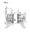
- Figs.1A through C show a not claimed embodiment of constituting a turning mechanism of a robot arm by using a planetary gear apparatus as a hollow speed reducer according to the invention
- Fig.1A is a plan view of a first not claimed embodiment
- Fig. 1B is a plan view of a second not claimed embodiment
- Fig.1C is a vertical sectional view of the first or the second embodiment which are not claimed.
- a hollow speed reducer 10 of the not claimed embodiment is a planetary gear apparatus comprising a crankshaft 11, a pinion 12 formed with outer teeth at an outer periphery thereof, fitted to a crank portion 11a of the crankshaft and eccentrically moved, and a case 13 an inner peripheral face of which is formed with inner teeth brought in mesh with the outer teeth of the pinion 12.
- the pinion 12 includes the outer teeth of a tooth shape comprising an equal distance curve to a pericycloidal curve at an outer peripheral face thereof.
- a support circular plate 14 and an end circular plate 15 of upper and lower sides of the hollow speed reducer 10 are integrally connected by a bolt 16, further, the support circular plate 14 is fastened to attach to a frame base 31 of a robot arm by the bolt 16.
- the case 13 of the hollow speed reducer 10 is rotatably supported at outer peripheral portions of the support circular plate 14 and the end circular plate 15 on upper and lower sides by a bearing.
- the crankshaft 11 is rotatably supported by upper and lower bearings 17 between the support circular plate 14 and the end circular plate 15.
- the crankshaft 11 includes two crank portions eccentrically arranged from a rotation axis by predetermined distances, and the pinion 12 is fitted to the crank portions.
- An inner portion of the hollow speed reducer 10 is formed with a hollow hole by a hollow circular pipe 18.
- One end of the hollow circular pipe 18 is fixed to the support circular plate 14, and other end thereof is brought into contact with an output member, mentioned later, by way of an oil seal.
- An outer periphery of the hollow circular pipe 18 is loosely fitted with a center gear 20, and the center gear 20 is rotatably supported by a bearing 19. Further, cables are passed through a hollow portion of the hollow gear speed reducer (hollow portion of the hollow circular pipe 18).
- eight motors 21 are provided to be distributed equally around a rotation axis center of the center gear 20 in the embodiment shown in Fig. 1A , further, in an embodiment shown in Fig.1B , respective twos of motors 21 are provided at two portions opposed to each other. Output shafts of the respective motors 21 are fastened to be attached with small gears 22 and the small gears 22 are brought in mesh with the center gear 20.
- rotation of the respective motors 21 is transmitted from the small gears 22 to the center gear 20, the crankshaft 11 is rotated by rotation of the center gear 20 to generate a crank movement, and the case 13 is rotated by way of a planetary movement of the pinion 12 fitted to the crankshaft by reducing a speed thereof.
- an output member 32 of a robot fastened to be attached to the case 13 of the hollow speed reducer 10 is turned by a decelerated speed.
- the turning angle of the output member 32 is within 360°.
- a plurality of the drive motors 21 can be constituted, the individual drive motor 21 can be downsized, thereby, a length in an axial direction of a turning structure can be shortened.
- the hollow speed reducer 10 which has been used in a background art can be used as it is, and manufacturing thereof is facilitated without changing the structure per se considerably.
- the machine can continuously be driven without being stopped by the remainingmotor 21. Thereby, even when the robot is failed, a time period of stopping a manufacturing line can be reduced more than the background art apparatus.
- the motor 21 which is not to be interchanged can be utilized as an attitude maintaining brake.
- a mechanical lock is separately prepared currently between a pivoting portion and a fixed portion, an interchanging operation can be carried out without preparing such a mechanical lock and the operation is extremely facilitated.
- the motors 21 are not completely detached, and therefore, according to the speed reducer of the invention, an original point returning operation of the robot can be carried out extremely easily.
- the turning structure can be shortened in the axial direction.
- the plurality of motors are respectively provided concentratedly at 180° symmetric positions relative to the rotation axis as in Fig. 1B , in addition to the above-described advantage,: there can also be achieved an effect of facilitating arrangement of cables, pipings or the like, and capable of arranging a support shaft or a drive shaft in a direction orthogonal to the rotation axis of the speed reducer.
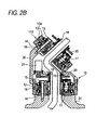
- Figs.2A through 2B show other embodiment constituting a turning mechanism of a robot arm by using a planetary gear apparatus as a hollow speed reducer according to the invention
- Fig. 2A is a plan view
- Fig. 2B is a vertical sectional view.
- an upper end of the output member 32 of the not claimed embodiment shown in Figs. 1A through 1C is inclined, and a front end portion of the inclined output member 32 is provided with a second hollow speed reducer 110 having a structure similar to that of the hollow speed reducer 10 of the above-described embodiment which is not claimed. That is, the support circular plate 14 and the end circular plate 15 on upper and lower sides of the secondhollow speed reducer 110 are integrally connected by the bolt 16, further, the support circular plate 14 of the hollow speed reducer 110 is fastened to be attached to the output member 32 of the hollow speed reducer 10 by the bolt 16.
- Other structure of the hollow speed reducer 110 is similar to that of the hollow speed reducer 10, the same members are attached with the same citation notations and detailed explanation thereof will be omitted.
- the center gear 20 of the hollow speed reducer 110 is connected with a motor (not illustrated) similar to the above-described motor 21.
- a second output member (not illustrated) is screwed to be attached to a screw hole 13a of the case 13 of the hollow speed reducer 110.
- the hollow speed reducer 110 on an upper side is rotated to be driven integrally with the output member 32 of the hollow speed reducer 10 on a lower side, and rotation of the motor attached to the hollow speed reducer 110 on the upper side is reduced in a speed thereof by the hollow speed reducer 110 on the upper side to thereby turn the second output member.
- the hollow speed reducers 10 and 110 are planetary gear apparatus each comprising the crankshaft 11, the pinion 12 formed with the outer teeth on the outer periphery, fitted to the crank portion 11a of the crankshaft 11 and eccentrically moved, and the case 13 the inner peripheral face of which is formed with the inner teeth brought in mesh with the outer teeth of the pinion 12.
- the hollow speed reducer can also be constituted by wave gear speed reducer comprising a wave generator 220, a flex-spline 230 and a circular spline 240.
- a hollow wave gear speed reducer 210 is constituted by the wave generator 220, the flex-spline 230 and the circular spline 240.
- a first sub plate 33 and the circular spline 240 of the hollow speed reducer 210 are fastened to attach to the frame base 31 of the first arm of the robot by the bolt 16.
- An outer periphery of the circular spline 240 is arranged with a cross roller bearing 250.
- An inner ring of the cross roller bearing 250 is integrally formed with the circular spline 240, and an outer ring of the cross roller bearing 250, a fixing portion 231 of an endportion of an outer side of the flex-spline 230 and a second sub plate 34 of the hollow speed reducer 210 are fastened to attach to the output member 32 by a bolt 17.
- An inner side of the flex-spline 230 is engaged with the wave generator 220 by way of a bearing 260.
- the wave generator 220 is rotatably supported by the first and the second sub plates 33 and 34 by a bearing 19.
- An inner portion of the hollow speed reducer 210 is formed with a hollow hole by the hollow circular pipe 18, one end of the hollow circular pipe 18 is fixed to the output member 32, and other end thereof is brought into contact with the frame base 31 of the first arm by way of an oil seal.
- An outer periphery of the hollow circular pipe 18 is loosely fitted with the wave generator 220, and the cables are passed through the hollow portion of the hollow gear speed reducer 210 (hollow portion of hollow circular pipe 18).
- the wave generator 220 is brought into spline-engagement 20a with the center gear 20.
- the plurality of motors 21 are provided at positions of the outer peripheral portion of the center gear 20, the small gears 22 are fastened to attach to the output shaft of the motor 21, and the small gear 22 is brought in mesh with the center gear 20. Further, the motor 21 can be arranged similar to the motor 21 of the embodiment mentioned above.
- rotation of the motor 21 is transmitted from the small gear 22 to the center gear 20, the wave generator 220 is rotated by rotation of the center gear 20 and a wave movement is generated by the flex-spline 230 and the circular spline 240.
- the output member 32 of the robot fastened to attach to the case 13 of the hollow speed reducer 210 is turned by a decelerated speed.
Claims (3)
- Hohles Untersetzungsgetriebe, das ein kreisförmiges Rohr (18) in seinem Innenabschnitt aufweist, wobei Kabel durch einen hohlen Abschnitt des kreisförmigen Rohrs (18) hindurchgeführt werden und ein Sonnenrad (20) als ein Eingang des hohlen Untersetzungsgetriebes (10, 110) an einer Position koaxial zu dem kreisförmigen Rohr (18) vorhanden ist, dadurch gekennzeichnet, dass kleine Zahnräder (22), die an Ausgangswellen einer Vielzahl von Motoren (21) vorhanden sind, gleichzeitig in Eingriff mit dem Sonnenrad (20) gebracht werden, ein oberes Ende eines Ausgangselementes (32) des hohlen Untersetzungsgetriebes geneigt ist und ein vorderer Endabschnitt des geneigten Ausgangselementes (32) des hohlen Untersetzungsgetriebes mit einem zweiten hohlen Untersetzungsgetriebe (110) versehen ist.
- Hohles Untersetzungsgetriebe nach Anspruch 1, wobei die Vielzahl von Motoren (21) konzentriert an Abschnitten eines Bereiches um eine Drehachse des Sonnenrades (20) herum vorhanden sind.
- Hohles Untersetzungsgetriebe nach Anspruch 1, wobei das hohle Untersetzungsgetriebe (10, 110) eine Planetenrad-Vorrichtung ist, die eine Kurbelwelle (11), ein Ritzel (12), das mit äußeren Zähnen an seinem Außenumfang versehen ist, auf einen Kurbelabschnitt der Kurbelwelle (11) aufgepasst ist und exzentrisch bewegt wird, sowie ein Gehäuse (13) umfasst, dessen Innenumfangsfläche mit inneren Zähnen versehen ist, die mit den äußeren Zähnen des Ritzels (12) in Eingriff gebracht werden.
Applications Claiming Priority (2)
| Application Number | Priority Date | Filing Date | Title |
|---|---|---|---|
| JP2005278635A JP2007085530A (ja) | 2005-09-26 | 2005-09-26 | 中空減速機 |
| PCT/JP2006/319071 WO2007034964A1 (ja) | 2005-09-26 | 2006-09-26 | 中空減速機 |
Publications (3)
| Publication Number | Publication Date |
|---|---|
| EP1930625A1 EP1930625A1 (de) | 2008-06-11 |
| EP1930625A4 EP1930625A4 (de) | 2010-04-14 |
| EP1930625B1 true EP1930625B1 (de) | 2013-01-16 |
Family
ID=37889005
Family Applications (1)
| Application Number | Title | Priority Date | Filing Date |
|---|---|---|---|
| EP06798337A Active EP1930625B1 (de) | 2005-09-26 | 2006-09-26 | Hohles untersetzungsgetriebe |
Country Status (6)
| Country | Link |
|---|---|
| US (1) | US8117945B2 (de) |
| EP (1) | EP1930625B1 (de) |
| JP (1) | JP2007085530A (de) |
| KR (1) | KR101258241B1 (de) |
| CN (1) | CN101273216B (de) |
| WO (1) | WO2007034964A1 (de) |
Families Citing this family (35)
| Publication number | Priority date | Publication date | Assignee | Title |
|---|---|---|---|---|
| US9879760B2 (en) | 2002-11-25 | 2018-01-30 | Delbert Tesar | Rotary actuator with shortest force path configuration |
| CN101680512B (zh) * | 2007-06-01 | 2012-07-25 | 纳博特斯克株式会社 | 带有电机的减速装置和产业机械 |
| JP5103283B2 (ja) * | 2007-06-11 | 2012-12-19 | 住友重機械工業株式会社 | ロボットの関節駆動装置 |
| JP5145099B2 (ja) * | 2008-03-28 | 2013-02-13 | ナブテスコ株式会社 | シール付き装置 |
| JP2010007830A (ja) * | 2008-06-30 | 2010-01-14 | Nabtesco Corp | 歯車装置 |
| JP2010023195A (ja) * | 2008-07-22 | 2010-02-04 | Nidec Sankyo Corp | 産業用ロボット |
| JP5130184B2 (ja) * | 2008-10-24 | 2013-01-30 | 住友重機械工業株式会社 | 回転検出器付き減速装置 |
| JP5270462B2 (ja) * | 2009-06-15 | 2013-08-21 | ナブテスコ株式会社 | 偏心揺動型歯車装置および偏心揺動型歯車装置におけるクランク軸の組み付け方法 |
| JP2011002063A (ja) * | 2009-06-19 | 2011-01-06 | Sumitomo Heavy Ind Ltd | 動力伝達装置 |
| US8733207B2 (en) * | 2011-03-23 | 2014-05-27 | Toyota Jidosha Kabushiki Kaisha | Method of driving joint device |
| JP2013052766A (ja) * | 2011-09-05 | 2013-03-21 | Jtekt Corp | 電動パワーステアリング装置 |
| JP2013052765A (ja) * | 2011-09-05 | 2013-03-21 | Jtekt Corp | 電動パワーステアリング装置 |
| CN102825599A (zh) * | 2012-09-08 | 2012-12-19 | 广西玉林正方机械有限公司 | 管状六自由度机器人本体 |
| US10414271B2 (en) | 2013-03-01 | 2019-09-17 | Delbert Tesar | Multi-speed hub drive wheels |
| US9862263B2 (en) | 2013-03-01 | 2018-01-09 | Delbert Tesar | Multi-speed hub drive wheels |
| US9365105B2 (en) | 2013-10-11 | 2016-06-14 | Delbert Tesar | Gear train and clutch designs for multi-speed hub drives |
| US10422387B2 (en) | 2014-05-16 | 2019-09-24 | Delbert Tesar | Quick change interface for low complexity rotary actuator |
| JP6271343B2 (ja) * | 2014-05-30 | 2018-01-31 | ナブテスコ株式会社 | 歯車装置 |
| US9657813B2 (en) | 2014-06-06 | 2017-05-23 | Delbert Tesar | Modified parallel eccentric rotary actuator |
| US9915319B2 (en) | 2014-09-29 | 2018-03-13 | Delbert Tesar | Compact parallel eccentric rotary actuator |
| JP6050307B2 (ja) * | 2014-12-16 | 2016-12-21 | 財團法人精密機械研究發展中心 | 中空遊星減速機 |
| US9506555B2 (en) | 2014-12-23 | 2016-11-29 | Precision Machinery Research & Development Center | Hollow-type planet speed reducer |
| US11014658B1 (en) | 2015-01-02 | 2021-05-25 | Delbert Tesar | Driveline architecture for rotorcraft featuring active response actuators |
| CN104964004A (zh) * | 2015-07-21 | 2015-10-07 | 巨轮股份有限公司 | 一种工业机器人rv减速器 |
| JP6174107B2 (ja) | 2015-12-21 | 2017-08-02 | 上銀科技股▲分▼有限公司 | 駆動伝達装置 |
| CN105773656B (zh) * | 2016-03-30 | 2018-06-22 | 广东工业大学 | 一种内走线机器人摆转关节模块 |
| JP6849363B2 (ja) * | 2016-03-30 | 2021-03-24 | 日本電産株式会社 | 回転アクチュエータおよびロボット |
| US10464413B2 (en) | 2016-06-24 | 2019-11-05 | Delbert Tesar | Electric multi-speed hub drive wheels |
| JP6756214B2 (ja) * | 2016-09-26 | 2020-09-16 | セイコーエプソン株式会社 | ロボット、歯車装置および歯車装置の製造方法 |
| US10197146B2 (en) * | 2016-12-28 | 2019-02-05 | Precision Machinery Research & Development Center | Reducer module with real-time torque sensing |
| CN106704493A (zh) * | 2017-01-24 | 2017-05-24 | 陕西理工学院 | 一种能够平衡环板惯性力矩的三环减速器 |
| EP3483473A1 (de) * | 2017-11-14 | 2019-05-15 | Kimex Group s.r.o. | Getriebe |
| JP6633605B2 (ja) * | 2017-12-22 | 2020-01-22 | ファナック株式会社 | ロボット |
| JP2019167966A (ja) * | 2018-03-22 | 2019-10-03 | 株式会社ニッセイ | 直交軸減速機及び直交軸減速機を用いたロボット |
| JP2022032789A (ja) * | 2020-08-14 | 2022-02-25 | セイコーエプソン株式会社 | 歯車装置およびロボット |
Citations (1)
| Publication number | Priority date | Publication date | Assignee | Title |
|---|---|---|---|---|
| US20010044356A1 (en) * | 2000-05-15 | 2001-11-22 | Teijin Seiki Co., Ltd. | Eccentric orbiting type speed reducer and joint for industrial machine equipped with the same |
Family Cites Families (18)
| Publication number | Priority date | Publication date | Assignee | Title |
|---|---|---|---|---|
| DE6936058U (de) * | 1969-09-12 | 1970-02-05 | Karl Hueller Ges Mit Beschraen | Getriebe fuer die vorschubbewegung von mechanischen schlitteneinheiten von werkzeugmaschinen |
| JPS6039518B2 (ja) * | 1980-09-30 | 1985-09-06 | ファナック株式会社 | 工業用ロボットの手首機構 |
| US4624621A (en) * | 1982-10-21 | 1986-11-25 | Kabushiki Kaisha Kobe Seiko Sho | Wrist mechanism for industrial robots and the like |
| JPS6155435A (ja) | 1984-08-27 | 1986-03-19 | Matsushita Electric Ind Co Ltd | 減速機 |
| CA1244855A (en) | 1985-01-18 | 1988-11-15 | Kazuyuki Matsumoto | Robot arm drive apparatus of industrial robot |
| JPH0641117B2 (ja) * | 1986-06-13 | 1994-06-01 | 株式会社日立製作所 | ロボツトの手首装置 |
| JPH04115592U (ja) | 1991-03-29 | 1992-10-14 | 邦男 高木 | ロボツトアーム |
| JPH07108485A (ja) | 1993-10-07 | 1995-04-25 | Fanuc Ltd | ロボット等の回転関節 |
| JP3596932B2 (ja) | 1995-02-21 | 2004-12-02 | ティーエスコーポレーション株式会社 | 駆動モータ付き偏心差動減速機 |
| JP4400806B2 (ja) * | 2000-02-04 | 2010-01-20 | 株式会社ハーモニック・ドライブ・システムズ | 中空アクチュエータ |
| US20010046918A1 (en) * | 2000-03-01 | 2001-11-29 | Harold Spanski | Gear drive transmission and method |
| AU2001241957A1 (en) | 2000-03-01 | 2001-09-12 | Harold Spanski | Gear drive transmission and method |
| JP4236023B2 (ja) | 2000-09-29 | 2009-03-11 | ナブテスコ株式会社 | モータ付き減速機 |
| JP4755357B2 (ja) | 2001-04-18 | 2011-08-24 | ナブテスコ株式会社 | 減速機 |
| JP2002349192A (ja) * | 2001-05-24 | 2002-12-04 | Iseki Poly-Tech Inc | 掘進機 |
| DE20213389U1 (de) * | 2002-08-30 | 2004-01-15 | Cameron Gmbh | Drehverstellvorrichtung |
| US7086309B2 (en) * | 2002-09-19 | 2006-08-08 | The Johns Hopkins University | Planetary-harmonic motor |
| JP2005007532A (ja) * | 2003-06-19 | 2005-01-13 | Nagase Integrex Co Ltd | 回転テーブル装置 |
-
2005
- 2005-09-26 JP JP2005278635A patent/JP2007085530A/ja active Pending
-
2006
- 2006-09-26 WO PCT/JP2006/319071 patent/WO2007034964A1/ja active Application Filing
- 2006-09-26 EP EP06798337A patent/EP1930625B1/de active Active
- 2006-09-26 KR KR1020087007334A patent/KR101258241B1/ko active IP Right Grant
- 2006-09-26 CN CN2006800354141A patent/CN101273216B/zh active Active
- 2006-09-26 US US12/088,118 patent/US8117945B2/en active Active
Patent Citations (1)
| Publication number | Priority date | Publication date | Assignee | Title |
|---|---|---|---|---|
| US20010044356A1 (en) * | 2000-05-15 | 2001-11-22 | Teijin Seiki Co., Ltd. | Eccentric orbiting type speed reducer and joint for industrial machine equipped with the same |
Also Published As
| Publication number | Publication date |
|---|---|
| CN101273216B (zh) | 2012-05-30 |
| EP1930625A1 (de) | 2008-06-11 |
| JP2007085530A (ja) | 2007-04-05 |
| CN101273216A (zh) | 2008-09-24 |
| EP1930625A4 (de) | 2010-04-14 |
| WO2007034964A1 (ja) | 2007-03-29 |
| KR101258241B1 (ko) | 2013-04-26 |
| US8117945B2 (en) | 2012-02-21 |
| KR20080047576A (ko) | 2008-05-29 |
| US20090233750A1 (en) | 2009-09-17 |
Similar Documents
| Publication | Publication Date | Title |
|---|---|---|
| EP1930625B1 (de) | Hohles untersetzungsgetriebe | |
| EP1889694B1 (de) | Drehteilstruktur eines industrieroboters | |
| US10677320B2 (en) | Epicyclic gear train | |
| US7603930B2 (en) | Rotary table apparatus | |
| EP2172671B1 (de) | Getriebevorrichtung sowie für einen industrieroboter eingestellte rotationsabschnittsstruktur mit der getriebevorrichtung | |
| EP2241782B1 (de) | Exzentrisches untersetzungsgetriebe | |
| EP2149724B1 (de) | Untersetzungsgetriebevorrichtung | |
| KR20000058349A (ko) | 내접식 유성치차 감속기 | |
| WO2010023815A1 (ja) | フレキシブルカップリング構造及びそれを備える舶用スラスタ装置 | |
| KR20120046096A (ko) | 하이브리드 감속기 | |
| JP5408840B2 (ja) | 2軸回転型ポジショナー | |
| US9017206B2 (en) | Gear device | |
| JP2013174271A (ja) | 減速装置、産業機械および減速装置の産業機械への組込方法 | |
| EP3358217B1 (de) | Drehzahlminderer | |
| CN107150353B (zh) | 机械手的关节驱动结构 | |
| JP2866249B2 (ja) | 内接噛合式遊星歯車構造を採用した増減速機シリーズ | |
| KR100788735B1 (ko) | 동력전달장치의 시리즈 및 기어드모터의 시리즈 | |
| JP2000065158A (ja) | 内歯揺動型内接噛合遊星歯車装置 | |
| US20220316183A1 (en) | Drive transmission device and construction machine | |
| KR20180021463A (ko) | 무게가 최소화된 고하중 구동모듈 | |
| EP3656931B1 (de) | Planetengetriebemodul für einen schwenkantrieb einer baumaschine | |
| KR101800673B1 (ko) | 동력전달장치 | |
| KR20200066200A (ko) | 산업 기계의 회전 기구, 감속기, 산업 기계 및 구동 장치 | |
| JPH02188224A (ja) | 大出力で作動できる少なくとも2本の作動シヤフトを備えた、たとえば二軸スクリユ押出機等用の装置 | |
| US11549569B2 (en) | Speed reducing device and drive device |
Legal Events
| Date | Code | Title | Description |
|---|---|---|---|
| PUAI | Public reference made under article 153(3) epc to a published international application that has entered the european phase |
Free format text: ORIGINAL CODE: 0009012 |
|
| 17P | Request for examination filed |
Effective date: 20080312 |
|
| AK | Designated contracting states |
Kind code of ref document: A1 Designated state(s): AT BE BG CH CY CZ DE DK EE ES FI FR GB GR HU IE IS IT LI LT LU LV MC NL PL PT RO SE SI SK TR |
|
| A4 | Supplementary search report drawn up and despatched |
Effective date: 20100315 |
|
| 17Q | First examination report despatched |
Effective date: 20100726 |
|
| 17Q | First examination report despatched |
Effective date: 20110311 |
|
| DAX | Request for extension of the european patent (deleted) | ||
| GRAP | Despatch of communication of intention to grant a patent |
Free format text: ORIGINAL CODE: EPIDOSNIGR1 |
|
| GRAS | Grant fee paid |
Free format text: ORIGINAL CODE: EPIDOSNIGR3 |
|
| GRAA | (expected) grant |
Free format text: ORIGINAL CODE: 0009210 |
|
| AK | Designated contracting states |
Kind code of ref document: B1 Designated state(s): AT BE BG CH CY CZ DE DK EE ES FI FR GB GR HU IE IS IT LI LT LU LV MC NL PL PT RO SE SI SK TR |
|
| REG | Reference to a national code |
Ref country code: GB Ref legal event code: FG4D |
|
| REG | Reference to a national code |
Ref country code: CH Ref legal event code: EP |
|
| REG | Reference to a national code |
Ref country code: IE Ref legal event code: FG4D |
|
| REG | Reference to a national code |
Ref country code: AT Ref legal event code: REF Ref document number: 594066 Country of ref document: AT Kind code of ref document: T Effective date: 20130215 Ref country code: CH Ref legal event code: EP |
|
| REG | Reference to a national code |
Ref country code: DE Ref legal event code: R096 Ref document number: 602006034271 Country of ref document: DE Effective date: 20130314 |
|
| REG | Reference to a national code |
Ref country code: AT Ref legal event code: MK05 Ref document number: 594066 Country of ref document: AT Kind code of ref document: T Effective date: 20130116 |
|
| REG | Reference to a national code |
Ref country code: NL Ref legal event code: VDEP Effective date: 20130116 |
|
| REG | Reference to a national code |
Ref country code: LT Ref legal event code: MG4D |
|
| PG25 | Lapsed in a contracting state [announced via postgrant information from national office to epo] |
Ref country code: CY Free format text: LAPSE BECAUSE OF FAILURE TO SUBMIT A TRANSLATION OF THE DESCRIPTION OR TO PAY THE FEE WITHIN THE PRESCRIBED TIME-LIMIT Effective date: 20130116 Ref country code: ES Free format text: LAPSE BECAUSE OF FAILURE TO SUBMIT A TRANSLATION OF THE DESCRIPTION OR TO PAY THE FEE WITHIN THE PRESCRIBED TIME-LIMIT Effective date: 20130427 Ref country code: LT Free format text: LAPSE BECAUSE OF FAILURE TO SUBMIT A TRANSLATION OF THE DESCRIPTION OR TO PAY THE FEE WITHIN THE PRESCRIBED TIME-LIMIT Effective date: 20130116 Ref country code: SE Free format text: LAPSE BECAUSE OF FAILURE TO SUBMIT A TRANSLATION OF THE DESCRIPTION OR TO PAY THE FEE WITHIN THE PRESCRIBED TIME-LIMIT Effective date: 20130116 Ref country code: BE Free format text: LAPSE BECAUSE OF FAILURE TO SUBMIT A TRANSLATION OF THE DESCRIPTION OR TO PAY THE FEE WITHIN THE PRESCRIBED TIME-LIMIT Effective date: 20130116 Ref country code: AT Free format text: LAPSE BECAUSE OF FAILURE TO SUBMIT A TRANSLATION OF THE DESCRIPTION OR TO PAY THE FEE WITHIN THE PRESCRIBED TIME-LIMIT Effective date: 20130116 Ref country code: IS Free format text: LAPSE BECAUSE OF FAILURE TO SUBMIT A TRANSLATION OF THE DESCRIPTION OR TO PAY THE FEE WITHIN THE PRESCRIBED TIME-LIMIT Effective date: 20130516 Ref country code: BG Free format text: LAPSE BECAUSE OF FAILURE TO SUBMIT A TRANSLATION OF THE DESCRIPTION OR TO PAY THE FEE WITHIN THE PRESCRIBED TIME-LIMIT Effective date: 20130416 |
|
| PG25 | Lapsed in a contracting state [announced via postgrant information from national office to epo] |
Ref country code: PL Free format text: LAPSE BECAUSE OF FAILURE TO SUBMIT A TRANSLATION OF THE DESCRIPTION OR TO PAY THE FEE WITHIN THE PRESCRIBED TIME-LIMIT Effective date: 20130116 Ref country code: LV Free format text: LAPSE BECAUSE OF FAILURE TO SUBMIT A TRANSLATION OF THE DESCRIPTION OR TO PAY THE FEE WITHIN THE PRESCRIBED TIME-LIMIT Effective date: 20130116 Ref country code: SI Free format text: LAPSE BECAUSE OF FAILURE TO SUBMIT A TRANSLATION OF THE DESCRIPTION OR TO PAY THE FEE WITHIN THE PRESCRIBED TIME-LIMIT Effective date: 20130116 Ref country code: NL Free format text: LAPSE BECAUSE OF FAILURE TO SUBMIT A TRANSLATION OF THE DESCRIPTION OR TO PAY THE FEE WITHIN THE PRESCRIBED TIME-LIMIT Effective date: 20130116 Ref country code: FI Free format text: LAPSE BECAUSE OF FAILURE TO SUBMIT A TRANSLATION OF THE DESCRIPTION OR TO PAY THE FEE WITHIN THE PRESCRIBED TIME-LIMIT Effective date: 20130116 Ref country code: PT Free format text: LAPSE BECAUSE OF FAILURE TO SUBMIT A TRANSLATION OF THE DESCRIPTION OR TO PAY THE FEE WITHIN THE PRESCRIBED TIME-LIMIT Effective date: 20130516 Ref country code: GR Free format text: LAPSE BECAUSE OF FAILURE TO SUBMIT A TRANSLATION OF THE DESCRIPTION OR TO PAY THE FEE WITHIN THE PRESCRIBED TIME-LIMIT Effective date: 20130417 |
|
| PG25 | Lapsed in a contracting state [announced via postgrant information from national office to epo] |
Ref country code: DK Free format text: LAPSE BECAUSE OF FAILURE TO SUBMIT A TRANSLATION OF THE DESCRIPTION OR TO PAY THE FEE WITHIN THE PRESCRIBED TIME-LIMIT Effective date: 20130116 Ref country code: RO Free format text: LAPSE BECAUSE OF FAILURE TO SUBMIT A TRANSLATION OF THE DESCRIPTION OR TO PAY THE FEE WITHIN THE PRESCRIBED TIME-LIMIT Effective date: 20130116 Ref country code: CZ Free format text: LAPSE BECAUSE OF FAILURE TO SUBMIT A TRANSLATION OF THE DESCRIPTION OR TO PAY THE FEE WITHIN THE PRESCRIBED TIME-LIMIT Effective date: 20130116 Ref country code: SK Free format text: LAPSE BECAUSE OF FAILURE TO SUBMIT A TRANSLATION OF THE DESCRIPTION OR TO PAY THE FEE WITHIN THE PRESCRIBED TIME-LIMIT Effective date: 20130116 Ref country code: EE Free format text: LAPSE BECAUSE OF FAILURE TO SUBMIT A TRANSLATION OF THE DESCRIPTION OR TO PAY THE FEE WITHIN THE PRESCRIBED TIME-LIMIT Effective date: 20130116 |
|
| PLBE | No opposition filed within time limit |
Free format text: ORIGINAL CODE: 0009261 |
|
| STAA | Information on the status of an ep patent application or granted ep patent |
Free format text: STATUS: NO OPPOSITION FILED WITHIN TIME LIMIT |
|
| 26N | No opposition filed |
Effective date: 20131017 |
|
| PG25 | Lapsed in a contracting state [announced via postgrant information from national office to epo] |
Ref country code: IT Free format text: LAPSE BECAUSE OF FAILURE TO SUBMIT A TRANSLATION OF THE DESCRIPTION OR TO PAY THE FEE WITHIN THE PRESCRIBED TIME-LIMIT Effective date: 20130116 |
|
| REG | Reference to a national code |
Ref country code: DE Ref legal event code: R097 Ref document number: 602006034271 Country of ref document: DE Effective date: 20131017 |
|
| PG25 | Lapsed in a contracting state [announced via postgrant information from national office to epo] |
Ref country code: MC Free format text: LAPSE BECAUSE OF FAILURE TO SUBMIT A TRANSLATION OF THE DESCRIPTION OR TO PAY THE FEE WITHIN THE PRESCRIBED TIME-LIMIT Effective date: 20130116 |
|
| REG | Reference to a national code |
Ref country code: CH Ref legal event code: PL |
|
| GBPC | Gb: european patent ceased through non-payment of renewal fee |
Effective date: 20130926 |
|
| REG | Reference to a national code |
Ref country code: FR Ref legal event code: ST Effective date: 20140530 |
|
| REG | Reference to a national code |
Ref country code: IE Ref legal event code: MM4A |
|
| PG25 | Lapsed in a contracting state [announced via postgrant information from national office to epo] |
Ref country code: LI Free format text: LAPSE BECAUSE OF NON-PAYMENT OF DUE FEES Effective date: 20130930 Ref country code: CH Free format text: LAPSE BECAUSE OF NON-PAYMENT OF DUE FEES Effective date: 20130930 Ref country code: IE Free format text: LAPSE BECAUSE OF NON-PAYMENT OF DUE FEES Effective date: 20130926 Ref country code: GB Free format text: LAPSE BECAUSE OF NON-PAYMENT OF DUE FEES Effective date: 20130926 |
|
| PG25 | Lapsed in a contracting state [announced via postgrant information from national office to epo] |
Ref country code: FR Free format text: LAPSE BECAUSE OF NON-PAYMENT OF DUE FEES Effective date: 20130930 |
|
| PG25 | Lapsed in a contracting state [announced via postgrant information from national office to epo] |
Ref country code: TR Free format text: LAPSE BECAUSE OF FAILURE TO SUBMIT A TRANSLATION OF THE DESCRIPTION OR TO PAY THE FEE WITHIN THE PRESCRIBED TIME-LIMIT Effective date: 20130116 |
|
| PG25 | Lapsed in a contracting state [announced via postgrant information from national office to epo] |
Ref country code: HU Free format text: LAPSE BECAUSE OF FAILURE TO SUBMIT A TRANSLATION OF THE DESCRIPTION OR TO PAY THE FEE WITHIN THE PRESCRIBED TIME-LIMIT; INVALID AB INITIO Effective date: 20060926 Ref country code: LU Free format text: LAPSE BECAUSE OF NON-PAYMENT OF DUE FEES Effective date: 20130926 |
|
| P01 | Opt-out of the competence of the unified patent court (upc) registered |
Effective date: 20230615 |
|
| PGFP | Annual fee paid to national office [announced via postgrant information from national office to epo] |
Ref country code: DE Payment date: 20230920 Year of fee payment: 18 |