EP1921024B1 - Emballage d'aiguilles - Google Patents
Emballage d'aiguilles Download PDFInfo
- Publication number
- EP1921024B1 EP1921024B1 EP06023122A EP06023122A EP1921024B1 EP 1921024 B1 EP1921024 B1 EP 1921024B1 EP 06023122 A EP06023122 A EP 06023122A EP 06023122 A EP06023122 A EP 06023122A EP 1921024 B1 EP1921024 B1 EP 1921024B1
- Authority
- EP
- European Patent Office
- Prior art keywords
- needle
- clamping lip
- needles
- holding device
- support plate
- Prior art date
- Legal status (The legal status is an assumption and is not a legal conclusion. Google has not performed a legal analysis and makes no representation as to the accuracy of the status listed.)
- Active
Links
Images


Classifications
-
- D—TEXTILES; PAPER
- D04—BRAIDING; LACE-MAKING; KNITTING; TRIMMINGS; NON-WOVEN FABRICS
- D04B—KNITTING
- D04B37/00—Auxiliary apparatus or devices for use with knitting machines
-
- B—PERFORMING OPERATIONS; TRANSPORTING
- B65—CONVEYING; PACKING; STORING; HANDLING THIN OR FILAMENTARY MATERIAL
- B65D—CONTAINERS FOR STORAGE OR TRANSPORT OF ARTICLES OR MATERIALS, e.g. BAGS, BARRELS, BOTTLES, BOXES, CANS, CARTONS, CRATES, DRUMS, JARS, TANKS, HOPPERS, FORWARDING CONTAINERS; ACCESSORIES, CLOSURES, OR FITTINGS THEREFOR; PACKAGING ELEMENTS; PACKAGES
- B65D85/00—Containers, packaging elements or packages, specially adapted for particular articles or materials
- B65D85/20—Containers, packaging elements or packages, specially adapted for particular articles or materials for incompressible or rigid rod-shaped or tubular articles
- B65D85/24—Containers, packaging elements or packages, specially adapted for particular articles or materials for incompressible or rigid rod-shaped or tubular articles for needles, nails or like elongate small articles
Definitions
- the invention relates to a packaging suitable as a needle receiving device, with the several needles in an orderly form can be kept ready for use.
- Needle receiving devices and needle packages of various types are known.
- the DE-PS 258019 an auxiliary device for knitting machines for easy replacement of needles.
- the auxiliary device includes two rails, which are clamped together by means of a clamp. Between the rails, the needles are to be taken either at their rear or their front hook-side end, wherein they are clamped between the rails.
- a clamping device with two strips known between which needles are clamped parallel to each other and spaced from each other.
- This clamping device also serves as an auxiliary device for easy replacement of needles.
- the US-PS 2771187 shows a letter box for sewing needles with an envelope in which a receiving pocket for needles is formed. The needles are pushed into the receiving pocket, after which the envelope is closed.
- the holding device has a flat needle carrier section and a clamping lip arranged opposite to it.
- the clamping lip is bent in the direction of the needle carrier portion and may be biased towards the needle carrier portion.
- the clamping lip is adapted to span one end of a needle therebetween and to clamp and thereby hold the needle against the needle carrier portion. It can be arranged side by side in this holding device, if necessary, many needles side by side, the clamping lip then holds the needles stretched against the needle carrier section.
- the clamping lip and the needle carrier section are preferably in direct direct contact with the needles.
- An advantage of the concept of the holding device according to the invention is that unlike needle bundling by means of elastic cords, O-rings, wires, rubber ring, etc. virtually any size large groups of needles can be accommodated in a needle receiving device. After taking some Needles, the remaining held by the needle receiving device needles remain organized as an association.
- the knitting tools or needles to be accommodated by the needle receiving device of the present invention need not have separate designated openings.
- the clamping lip is bent in the direction of the needle carrier section.
- the distance between the underside of the clamping lip and the upper side of the needle carrier section is smaller than the height of the male knitting tool to be accommodated.
- the recorded knitting tools are biased against the needle carrier section with such a force that the accommodated needles are automatically held in position.
- the clamping lip preferably has some elasticity with respect to a direction transverse to the longitudinal direction of the needles, so that it presses all adjacent needles evenly against the needle carrier portion, regardless of any smaller tolerances.
- the needles can be held in the holding device without connection to each other. Only the clamping lip holds the needles together as a block. However, it is also possible to additionally secure the needles with each other.
- the needles can be interconnected by fixing lacquer or by mechanical means, such as a rubber cord. If the needles each have a suitable opening and these openings of the needles are aligned with each other, a direct rubber cord can be drawn through these openings. When released, it will stretch longitudinally together and expands in the radial direction. She can clamp the needles sitting on her, which then form a block held together. Such a block can be reliably picked up and stored by the holding device according to the invention.
- the needle carrier section may include structures, e.g. in the form of angled edges, which prevent lateral slippage of the held needles.
- the needles can also be held down by means of an elastic band or a suitable band.
- the clamping lip spans the needles mounted by the holding device.
- the clamping lip is bent so far at its free end following a pressure or contact point with the needle that a trouble-free insertion of the male needles is possible.
- the clamping lip is preferably at least so long that it completely spans the stitch-forming region of the inserted needle, so that the stitch-forming region is received by the receiving space formed in the holding device. While the needles rest with their needle back on the flat needle carrier section over a greater length or over the entire length, the clamping lip presses only at one point on each needle.
- the receiving device consists of at least two parts in the form of a Nadelhaltespange and connected to the Nadelhaltespange support plate.
- the clamping lip is formed as part of the Nadelhaltespange.
- the support plate is preferably made of another material, such as. Cardboard, also plastic, another plastic.
- the Nadelhaltespange and the support plate may be formed of the same or different metals.
- the carrier plate itself is absorbent or provided with an absorbent covering, for example a felt covering or another textile covering, it can form a storage means for preservatives or treatment substances.
- an absorbent covering for example a felt covering or another textile covering
- the carrier plate can form a storage means for preservatives or treatment substances.
- This opens up the possibility in the needle receiving means of substances such as corrosion inhibitors, e.g. suitable oil, which is then gradually released to the needles to protect them. This enables the world-wide delivery of needles of the highest quality and long-term storage even under adverse environmental conditions.
- a slot is provided for connecting the carrier plate with the Nadelhaltespange in one of the legs of the Nadelhaltespange, in which the carrier plate is inserted.
- the slot may be bounded by two equally long or unequal length walls.
- a slope or ramp is formed on a front edge of the knitting tools or needles facing wall, which facilitates the insertion of the needles. If the lower wall remote from the needles is longer than the upper wall, the needles, on the one hand, are in contact with the carrier plate over a large length and, on the other hand, the carrier plate is stiffened by the lower wall.
- one of the two walls delimiting the slot at the slot mouth may be chamfered, rounded or tapered.
- the carrier plate may be provided in the slot between which an edge of the inserted carrier plate is held.
- projections or ribs may be formed, which hold or clamp the carrier plate between each other. This has the advantage that the support plate is clamped or stored clamped at two spaced-apart defined strip or line-shaped areas. This is for the precise alignment of the carrier plate and the Nadelhaltespange each other.
- the slot may include a binder in the form of an adhesive that cohesively bonds the carrier plate to the needle retaining clip.
- the support plate can not only be held in the slot materially. It is also possible to connect the carrier plate with the Nadelhaltespange positive. This is, for example, possible by means of more or less sharp-edged ribs, which are impressed on one or two sides into the carrier plate and which are connected to the needle-holding clasp.
- suitable needle receiving device of the needle holding clasp is associated with an actuator.
- the actuating device is preferably adapted to move the clamping lip away from the carrier plate upon actuation, so that the needles can be slid without problems between the clamping lip and the carrier plate. When inserting or removing, the needles do not have to apply the force required to open the clamping lip.
- an actuating device are, for example, projections which extend beyond the elastic region which connects the clamping lip with the support plate, approximately parallel or at an acute angle to each other.
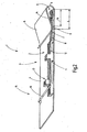
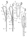
- FIG. 1 a needle holder 1 is illustrated with needles 2 received in the needle holder 1.
- the needle holder 1 serves, for example, as a needle package for needle shipping and for storing and keeping ready the needles. It can also only form part of a needle package.
- the needle holding device 1 has a receiving device 3, to which a flat needle carrier section 4 and a clamping lip 5 arranged opposite thereto belong.
- the flat, preferably flat and in plan view rectangular needle carrier portion 4 and the clamping lip 5 may be interconnected by an example arcuate spring portion 6. This biases the clamping lip 5 against the needle carrier section 4 and keeps the clamping lip 5 simultaneously pivotable. It forms a spring hinge.
- the clamping lip 5 and the needle carrier portion 4 may be integrally connected to each other via the spring portion 6.
- the needle carrier section 4, the clamping lip 5 and the spring section 6 of a suitable relatively stiff, but somewhat flexible material such as. Plastic.
- the clamping lip 5 preferably has an edge 7 bent away from the needle carrier section.
- the clamping lip 5 starting from the spring portion 6, initially approaches at an acute angle to the needle carrier section 4 up to a contact point 8, where it touches the needles 2 and then again runs to form an insertion funnel at an acute angle to the needle carrier section. 4 from the contact point 8 and the needle carrier portion 4 away.
- the clamping lip 5 encloses an inner space 9 into which the needles 2 protrude with their stitch-forming portions 10. These include the hooks of the needles, the needle breast and a part of the needle shaft.
- the interior 9 has a corresponding length L, which is defined by the length of the clamping lip 5, ie the distance of the contact point 8 of the spring portion 6.
- the clamping lip 5 is shorter than the shanks 11 of the needles 2, so that the other adjoining a step parts 12 of the needle body and their feet 13 are outside the interior 9 and lie on the needle carrier section 4.
- the needles 2 are pressed firmly against the needle carrier section 4 by the clamping action of the clamping lip 5 and thereby held as a block.
- a formed by the stitch forming part 10 of each needle 2 end 14 is held in the interior 9 while the remaining parts 12 of all needles 2 remain outside of this interior 9.
- the holder of the needles 2 is thus effected only by the clamping action of the clamping lip 5 on the needle shaft between the stitch-forming part and a subsequent to the shaft stage.
- the needle carrier portion 4 may be such that the friction coefficient between the needle bottom (needle back) and the needle carrier portion 4 is as high as possible.
- An increase in friction can also be achieved by structuring in the form of small elevations, webs or nubs. This ensures that the needles 2 can hardly move laterally on the support plate 4.
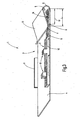
- additional means 15 for fixing the needles 2 may be provided on the needle carrier section 4.
- Such means 15 may, for example, in the form of a or several bands 16 may be formed, which overlap the needles 2 transversely and additionally hold.
- banderoles 16 can also serve as a tamper-evident closure. They may, as shown, be arranged at the free end of the needles 2 or between their feet 13. It is then necessary to remove them before needles 2 can be removed. If the bands 16 made of paper or plastic, they must be torn or cut to it. Alternatively, if it is possible to dispense with a tamper-evident closure, it is possible to provide resealable bands 16. Otherwise applies to the embodiment according to FIG. 2 on the basis of the introduced reference numerals used for FIG. 1 appropriate description accordingly.
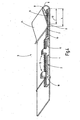
- FIG. 3 Another modification shows FIG. 3 ,
- the previous description of FIG. 1 or alternatively the FIG. 2 applies accordingly for FIG. 3
- one or more projections for example, in the form of an angled edge 17 oriented parallel to the needles 2, are formed on the needle carrier section 4.
- At the opposite longitudinal edge of the needle carrier section 4 can also be an angled in FIG. 3 but not further illustrated edge be provided.
- the edge 17 can be surrounded by a band, a rubber band or another packaging, for example. In the form of a plastic bag, a Kunststoffschrumpfschlauchs or the like.
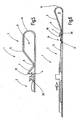
- FIG. 4 Another modification of the needle-holding device 1 is made FIG. 4 out.
- the needles 2 can be held together by a rubber band 18 that spans the needle carrier section 4 and the needles 2.
- the clamping lip 5 may be formed substantially flat or bent at an angle to the needles 2 extending bending line 44.
- the edge 7 terminates in an edge 19 whose distance h 1 to the needle carrier section 4, when no needle is inserted into the interior 9, is greater than the height h 2 of the hook top of a hook 20 one with its needle back on the needle carrier section
- the bias of the spring portion 6 can be so dimensioned that the clamping lip 5 rests with the contact point 8 on the needle carrier section 4 or defines a narrow gap with this. In any case, this gap is narrower than the height of the shaft 11 of the needle 2 to be stored.
- the possible spring stroke of the spring section 6 is greater than the height h 2 .
- the contact point 8 moves over the hook 20 and the stitch-forming portion 10 of each needle 2.
- the hooks 20 of the needles and any tongues 21 in the interior 9, where they learn no further contact with other parts.
- the contact point 8 maintains a safe distance to the hook 20 and the tongue 21 a.
- the clamping lip thus engages over the stitch-forming part 10 of each needle 2.
- the needle carrier section 4 and the clamping lip 5 together with the spring section 6 may be formed as separate parts which consist of identical or different materials and are connected to one another.
- the receiving device 3 may be formed by a needle holding clip 22 and a needle carrier plate 23.
- the carrier plate 23 is, for example, a cardboard while the needle-holding clip 22 is made of plastic, for example.
- the Nadelhaltespange 22 is an element consisting of three parts.
- the clamping lip 5 is connected via the spring portion 6 with the leg 24 which carries the support plate 23.
- the support plate 23 is connected to the leg 24 via a connecting means 25.
- an adhesive joint is used for this, in which the carrier plate 23 is glued over a large area to the leg 24.
- the leg 24 is preferably longer than the clamping lip 5. With the contact point 8, the clamping lip 5 can press the support plate 23 against the leg 24.
- the connecting means 25 may, like the FIGS. 8 to 11 also include a slot 26 formed in the leg 24.
- a first related embodiment illustrates FIG. 8 ,
- the slot 26 is oriented parallel to the support plate 23 and bounded by two walls 27, 28. These are arranged parallel to one another and parallel to the carrier plate 23.
- the support plate 23 is inserted in the slot 26 and connected to the Nadelhaltespange 22. This can serve as a bonding agent adhesive, for example, connects the wall 27 with the support plate 23. Also, adhesive may be provided in the slot 26 to assist in the connection.
- the wall 28 is provided at its edge adjacent to the slot 26 with a slope 29 or ramp surface. This forms a gently rising transition from the support plate 23 to the interior 9 facing surface of the wall 28.
- the slope 29 facilitates the insertion of needles in the interior.
- FIG. 9 shows.
- the bevel 29 in turn facilitates the insertion of needles under the edge 7, which, as in all the embodiments described above, with the support plate 23 and the wall 28 (Fig. FIG. 9 and 11 ) defines an insertion funnel 30.
- the needle receiving device 3 is in turn formed by the clamping lip 5 and the support plate 23.
- the bottom wall 27 may be provided on its slot inside with a slope 31 running towards the edge of the slot. This facilitates the insertion of the support plate 23 in the slot 26.
- the connection between the support plate 23 and leg 24 may in turn be made by a connecting means 25, for example adhesive.
- the leg 24 may also be formed shorter than the clamping lip 5. This is especially true when the carrier plate 23 is relatively stiff. Both walls 27, 28 may be provided with the previously described bevels 29, 31, on the one hand the insertion of the needles in the interior 9 and on the other hand, the insertion of the support plate 23 in the slot 26 to facilitate.
- both walls 27, 28 be longer than the clamping lip 5 and thus protrude beyond the contact point 8 addition. Again, the slopes 29, 31 are present.
- FIGS. 12 and 13 Other ways to connect between the support plate 23 and the leg 24 illustrate the FIGS. 12 and 13 ,
- the here gleichlang trained and rounded edges at their edges 27, 28 enclose an interior space 32 whose perpendicular to the support plate 23 to be measured width is greater than the thickness of the support plate 23.
- rib-like projections 33, 34 formed at the free end of the walls 27, 28 .
- rib-like projections 35, 36 are formed, which define a distance 37 between each other. This corresponds approximately to the thickness of the support plate 23 or is slightly smaller than the same.
- the support plate 23 may, as FIG. 13 shows, with corresponding, the projections 33, 34 associated recesses be provided. If the carrier plate 23 is somewhat yielding, these depressions can also be shaped under the action of the force formed by the projections 33, 34.
- the support plate 23 is thus held in two linear zones which are defined by positioning means, on the one hand by the projections 33, 34 and on the other by the elevations 35, 36.
- the support plate 23 may be kept very precise in this way, the interior 32 may be filled with adhesive 38, moreover, to secure the support plate 23 to the leg 24.
- FIGS. 14 and 15 Further modifications illustrate the FIGS. 14 and 15 , As FIG. 14 combined with FIG. 15 can, starting from the embodiment according to FIG. 7 on the leg 24 at a preferably opposite to the contact point 8 a rib 39 may be formed. This may be triangular in cross section and have an edge to be pointed on the leg 5. This is expressed in the example. From cardboard existing carrier plate 23 and thus secures them in the longitudinal direction. For further connection between the support plate 23 and the leg 24 in turn adhesive 40 may be provided.
- the Nadelhaltespange 22 may be provided with an actuating device 41 in order to open the clamping lip 5 controlled and close.
- the actuating device 41 is formed, for example, by extensions 42, 43, which adjoin the leg 24 or the clamping lip 5 and extend beyond the spring portion 6 forming a hinge.
- the extensions 42, 43 may extend over the entire width of the Nadelhaltespange 22, transverse to the needles 2 and in FIG. 14 oriented perpendicular to the plane of the drawing. Due to the rigid connection between the extension 42 and the clamping lip 5 and the rigid connection between the extension 43 and the leg 24 of the leg 5 is moved away from the support plate 23 when the two extensions 42, 43, for example, be compressed by hand. This makes it possible to introduce needles into the interior 9 without the contact point 8 having to touch the hook and the tongue. In addition, needles can be removed from the interior 9 without the hooks have to push out the clamping lip 5 from its clamping position.
- the support plate 23 may be formed of an absorbent material or be provided with such a whole or partial area. This applies to all embodiments described above.
- a needle holding device 1 which is particularly suitable as a packaging, has a flat needle carrier section 4 and a subsequent section, which has a clamping lip 5, which is resiliently tensioned against the needle carrier section 4.
- the clamping lip 5 engages over the stitch-forming portions 10 of needles 2, which are held adjacent to each other adjacent to each other on the needle carrier section 4.
- the resilient clamping lip 5 allows insertion and removal of one, several or all needles 2.
Landscapes
- Engineering & Computer Science (AREA)
- Mechanical Engineering (AREA)
- Textile Engineering (AREA)
- Packaging Of Annular Or Rod-Shaped Articles, Wearing Apparel, Cassettes, Or The Like (AREA)
Claims (9)
- Dispositif porte-aiguilles (1), destiné en particulier à des aiguilles à tricoter (2),
comprenant un dispositif de réception (3) qui présente une partie de support d'aiguilles (4) plate reliée par une partie élastique (6) à une lèvre de serrage (5) disposée en vis-à-vis de la partie de support d'aiguilles (4),
la lèvre de serrage (5) étant appliquée contre la partie de support d'aiguilles (4) avec une précontrainte qui est prévue telle que la lèvre de serrage (5) soit en appui avec un point de contact (8) sur la partie de support d'aiguilles (4), lorsqu'aucune aiguille (2) n'est maintenue entre la lèvre de serrage (5) et la partie de support d'aiguilles (4),
la lèvre de serrage (5) enfermant une cavité (9) qui est agencée pour recevoir une extrémité (14) de l'aiguille (2) constituée de la partie (10) de formation de mailles, sachant qu'une aiguille (2) insérée est pressée par la lèvre de serrage (5) contre la partie de support d'aiguilles (4) et est ainsi maintenue, tandis que les autres parties (12) de l'aiguille (2) restent à l'extérieur de la cavité (9) et l'aiguille est appliquée avec son dos contre la partie de support (4) plate, sur une longueur relativement grande ou sur toute la longueur. - Dispositif porte-aiguilles selon la revendication 1, caractérisé par le fait que la lèvre de serrage (5) présente un bord (7) qui est incurvé dans la direction opposée à la partie de support d'aiguilles (4) et est destiné à former un entonnoir d'insertion (30) pour faciliter l'engagement d'aiguilles (2) dans une cavité (9) formée entre la lèvre de serrage (5) et la partie de support d'aiguilles (4).
- Dispositif porte-aiguilles selon la revendication 1, caractérisé par le fait que le dispositif de réception (3) présente une boucle de maintien d'aiguilles (22) et une plaque de support (23) reliée à la boucle (22), la lèvre de serrage (5) faisant partie intégrante de la boucle de maintien d'aiguilles (22).
- Dispositif porte-aiguilles selon la revendication 3, caractérisé par le fait que la plaque de support (23) est réalisée en un matériau différent de celui de la boucle de maintien d'aiguilles (22) et est reliée à celle-ci par un moyen d'assemblage (25).
- Dispositif porte-aiguilles selon la revendication 3, caractérisé par le fait que la boucle de maintien d'aiguilles (22) est constituée de la lèvre de serrage (5), de la branche (24) et de la partie élastique (6), la branche (24) tenant la partie de support d'aiguilles (4).
- Dispositif porte-aiguilles selon la revendication 3, caractérisé par le fait que la boucle de maintien d'aiguilles (22) présente une fente (26) dans laquelle est insérée la plaque de support (23).
- Dispositif porte-aiguilles selon la revendication 6, caractérisé par le fait que dans la fente (26), il est prévu des moyens de positionnement (33, 34, 35, 36) pour la plaque de support (4, 23).
- Dispositif porte-aiguilles selon la revendication 3, caractérisé par le fait que la plaque de support (4, 23)est conçue pour distribuer un produit de traitement.
- Dispositif porte-aiguilles selon la revendication 3, caractérisé par le fait qu'un dispositif d'actionnement (41) est associé à la boucle de maintien d'aiguilles (22).
Priority Applications (6)
| Application Number | Priority Date | Filing Date | Title |
|---|---|---|---|
| EP06023122A EP1921024B1 (fr) | 2006-11-07 | 2006-11-07 | Emballage d'aiguilles |
| DE502006006050T DE502006006050D1 (de) | 2006-11-07 | 2006-11-07 | Nadelaufnahmeeinrichtung |
| CN2007101850450A CN101177841B (zh) | 2006-11-07 | 2007-11-06 | 针夹持装置 |
| KR1020070112527A KR100920653B1 (ko) | 2006-11-07 | 2007-11-06 | 바늘 수납장치 |
| US11/979,593 US8196743B2 (en) | 2006-11-07 | 2007-11-06 | Needle-receiving device |
| JP2007289447A JP4829203B2 (ja) | 2006-11-07 | 2007-11-07 | 針収容装置 |
Applications Claiming Priority (1)
| Application Number | Priority Date | Filing Date | Title |
|---|---|---|---|
| EP06023122A EP1921024B1 (fr) | 2006-11-07 | 2006-11-07 | Emballage d'aiguilles |
Publications (2)
| Publication Number | Publication Date |
|---|---|
| EP1921024A1 EP1921024A1 (fr) | 2008-05-14 |
| EP1921024B1 true EP1921024B1 (fr) | 2010-01-27 |
Family
ID=37499463
Family Applications (1)
| Application Number | Title | Priority Date | Filing Date |
|---|---|---|---|
| EP06023122A Active EP1921024B1 (fr) | 2006-11-07 | 2006-11-07 | Emballage d'aiguilles |
Country Status (6)
| Country | Link |
|---|---|
| US (1) | US8196743B2 (fr) |
| EP (1) | EP1921024B1 (fr) |
| JP (1) | JP4829203B2 (fr) |
| KR (1) | KR100920653B1 (fr) |
| CN (1) | CN101177841B (fr) |
| DE (1) | DE502006006050D1 (fr) |
Families Citing this family (7)
| Publication number | Priority date | Publication date | Assignee | Title |
|---|---|---|---|---|
| EP2280106B1 (fr) * | 2009-07-30 | 2012-02-15 | Groz-Beckert KG | Outil textile doté d'une protection temporaire |
| EP2405044B1 (fr) * | 2010-07-05 | 2012-09-19 | Groz-Beckert KG | Dispositif de retenue pour outils à tricot |
| PT2671821T (pt) * | 2012-06-08 | 2019-09-18 | Groz Beckert Kg | Embalagem destinada à guarda, de forma ordenada e alinhada, de objectos, e procedimento para a sua fabricação |
| US9481951B2 (en) * | 2013-07-25 | 2016-11-01 | David C. Fegley | Needle nook |
| US10940991B2 (en) | 2017-05-04 | 2021-03-09 | Knitting Fever, Inc. | Device for storing and displaying knitting/crocheting needles |
| CN107284811A (zh) * | 2017-06-14 | 2017-10-24 | 南通华夏制针科技有限公司 | 织针包装盒 |
| ES3014430T3 (en) * | 2021-09-15 | 2025-04-22 | Karl Mayer Stoll R&D Gmbh | Warp knitting tool bar |
Family Cites Families (16)
| Publication number | Priority date | Publication date | Assignee | Title |
|---|---|---|---|---|
| DE258019C (fr) | ||||
| DE260953C (fr) * | ||||
| US2551012A (en) * | 1951-05-01 | Knitting needle carrier | ||
| US1559698A (en) * | 1924-03-17 | 1925-11-03 | Leo A Henter | Comb and clip |
| US2549200A (en) * | 1949-06-13 | 1951-04-17 | J A Burks | Paper and pencil clip |
| BE538880A (fr) * | 1954-06-11 | |||
| US2771187A (en) * | 1955-05-09 | 1956-11-20 | Free Sewing Machine Co | Needle packet |
| US3566083A (en) * | 1967-10-16 | 1971-02-23 | Measurement Research Center In | Sensor for punches and marks |
| JPS6089180U (ja) * | 1983-11-21 | 1985-06-19 | クロバー株式会社 | 編針収納容器 |
| DE9209580U1 (de) * | 1992-07-17 | 1992-11-12 | Theodor Groz & Söhne & Ernst Beckert Nadelfabrik KG, 7470 Albstadt | Verpackungs- und Aufbewahrungsbehältnis für Strickmaschinennadeln |
| US5913618A (en) * | 1995-12-01 | 1999-06-22 | Yosha; Victor J. | Unitary credit card and paper money clip |
| US5944080A (en) * | 1997-05-22 | 1999-08-31 | Podwika; Paul P. | Money and card holder |
| DE10244315B4 (de) * | 2002-09-23 | 2006-01-05 | Groz-Beckert Kg | Werkzeugträger für Schiebernadeln und Versandeinheit |
| DE10305017A1 (de) * | 2003-02-07 | 2004-08-26 | Groz-Beckert Kg | Nadelverpackung und Nadeltasche, sowie Verpackungsverfahren |
| USD486862S1 (en) * | 2003-03-05 | 2004-02-17 | Pharmadesign, Inc. | Clip for attachment to a clipboard for holding paper and other objects |
| DE10325671B4 (de) * | 2003-06-06 | 2007-03-01 | Groz-Beckert Kg | Versandeinheit länglicher Systemteile, insbesondere Nadeln, für maschenbildende Maschinen |
-
2006
- 2006-11-07 EP EP06023122A patent/EP1921024B1/fr active Active
- 2006-11-07 DE DE502006006050T patent/DE502006006050D1/de active Active
-
2007
- 2007-11-06 CN CN2007101850450A patent/CN101177841B/zh not_active Expired - Fee Related
- 2007-11-06 KR KR1020070112527A patent/KR100920653B1/ko not_active Expired - Fee Related
- 2007-11-06 US US11/979,593 patent/US8196743B2/en active Active
- 2007-11-07 JP JP2007289447A patent/JP4829203B2/ja not_active Expired - Fee Related
Also Published As
| Publication number | Publication date |
|---|---|
| KR20080041582A (ko) | 2008-05-13 |
| DE502006006050D1 (de) | 2010-03-18 |
| CN101177841B (zh) | 2011-06-08 |
| JP4829203B2 (ja) | 2011-12-07 |
| CN101177841A (zh) | 2008-05-14 |
| JP2008114925A (ja) | 2008-05-22 |
| US20080105577A1 (en) | 2008-05-08 |
| US8196743B2 (en) | 2012-06-12 |
| KR100920653B1 (ko) | 2009-10-09 |
| EP1921024A1 (fr) | 2008-05-14 |
Similar Documents
| Publication | Publication Date | Title |
|---|---|---|
| DE2743900C3 (de) | Chirurgische Klammer und Klammermagazin zur Aufnahme und Verformung derselben | |
| EP0575026B1 (fr) | Dispositif de serrage | |
| EP1400619B1 (fr) | Porte-outil pour aiguilles à coulisses et unité de transport | |
| DE9012406U1 (de) | Nachfüllbarer Spender für selbsthaftendes, zickzackgefaltetes Notizpapier | |
| DE2948598C2 (de) | Trageverpackung, Verfahren und Vorrichtung zum Verschließen | |
| DE1503079A1 (de) | Nagelstreifen mit Vollkopfnaegeln | |
| DE2832707C3 (de) | Amboßelement zur Anbringung an dem Nasenteil eines chirurgischen Klammerinstruments | |
| EP1921024B1 (fr) | Emballage d'aiguilles | |
| CH636304A5 (de) | Halterung zum heften von loseblattmaterial. | |
| EP1353862B1 (fr) | Emballage pour aiguilles | |
| DE69012089T2 (de) | Band zum Halten von Nägeln. | |
| DE3629101A1 (de) | Kassette fuer eine heftmaschine | |
| DE1804237A1 (de) | Klemmvorrichtung zur Aufnahme von ungelochtem Schriftgut | |
| EP2309430A1 (fr) | Adaptateur pour une mini-carte UICC | |
| DE102007000850A1 (de) | Kartusche für eine auspressbare Masse | |
| DE202005021875U1 (de) | Mit Drahthakenverbindern versehenes Ende eines Bandes | |
| DE1229498B (de) | Schnellhefter mit einer Innentasche | |
| DE102007034862A1 (de) | Verfahren zur Herstellung einer Verpackung und Warenschieber zum Einsatz in einer Verpackung | |
| DE4234787C2 (de) | Aufnahmevorrichtung | |
| EP1310682B1 (fr) | Fixation pour des objets sphériques ou plats | |
| DE4230944A1 (de) | Eckenschutzelement für einen zu einem Transportgebinde zusammengefaßten Stapel stoßempfindlicher Plattenelemente sowie Verfahren zur Herstellung eines solchen Transportgebindes | |
| DE3004908A1 (de) | Abschlussteil zum loesbaren haltern mindestens eines blattes, verfahren und verwendung desselben sowie ausgabevorrichtung fuer abschlussteile | |
| DE10054460C2 (de) | Hefter | |
| EP1138523B1 (fr) | Dispositif de rangement pour classeurs ou reliures à anneaux | |
| WO2019219113A1 (fr) | Dispositif servant à conserver une cartouche pour une imprimante à jet d'encre ainsi qu'élément d'étanchéité de buse destiné à être utilisé dans un dispositif de ce type, et procédé de montage |
Legal Events
| Date | Code | Title | Description |
|---|---|---|---|
| PUAI | Public reference made under article 153(3) epc to a published international application that has entered the european phase |
Free format text: ORIGINAL CODE: 0009012 |
|
| AK | Designated contracting states |
Kind code of ref document: A1 Designated state(s): AT BE BG CH CY CZ DE DK EE ES FI FR GB GR HU IE IS IT LI LT LU LV MC NL PL PT RO SE SI SK TR |
|
| AX | Request for extension of the european patent |
Extension state: AL BA HR MK RS |
|
| 17P | Request for examination filed |
Effective date: 20080524 |
|
| 17Q | First examination report despatched |
Effective date: 20080729 |
|
| AKX | Designation fees paid |
Designated state(s): DE FR GB IT TR |
|
| GRAP | Despatch of communication of intention to grant a patent |
Free format text: ORIGINAL CODE: EPIDOSNIGR1 |
|
| GRAS | Grant fee paid |
Free format text: ORIGINAL CODE: EPIDOSNIGR3 |
|
| GRAA | (expected) grant |
Free format text: ORIGINAL CODE: 0009210 |
|
| AK | Designated contracting states |
Kind code of ref document: B1 Designated state(s): DE FR GB IT TR |
|
| REG | Reference to a national code |
Ref country code: GB Ref legal event code: FG4D Free format text: NOT ENGLISH |
|
| REF | Corresponds to: |
Ref document number: 502006006050 Country of ref document: DE Date of ref document: 20100318 Kind code of ref document: P |
|
| PLBE | No opposition filed within time limit |
Free format text: ORIGINAL CODE: 0009261 |
|
| STAA | Information on the status of an ep patent application or granted ep patent |
Free format text: STATUS: NO OPPOSITION FILED WITHIN TIME LIMIT |
|
| 26N | No opposition filed |
Effective date: 20101028 |
|
| REG | Reference to a national code |
Ref country code: FR Ref legal event code: PLFP Year of fee payment: 10 |
|
| PGFP | Annual fee paid to national office [announced via postgrant information from national office to epo] |
Ref country code: FR Payment date: 20151119 Year of fee payment: 10 |
|
| REG | Reference to a national code |
Ref country code: FR Ref legal event code: ST Effective date: 20170731 |
|
| PG25 | Lapsed in a contracting state [announced via postgrant information from national office to epo] |
Ref country code: FR Free format text: LAPSE BECAUSE OF NON-PAYMENT OF DUE FEES Effective date: 20161130 |
|
| PGFP | Annual fee paid to national office [announced via postgrant information from national office to epo] |
Ref country code: GB Payment date: 20230914 Year of fee payment: 18 |
|
| PGFP | Annual fee paid to national office [announced via postgrant information from national office to epo] |
Ref country code: TR Payment date: 20231106 Year of fee payment: 18 Ref country code: IT Payment date: 20231010 Year of fee payment: 18 Ref country code: DE Payment date: 20231130 Year of fee payment: 18 |
|
| REG | Reference to a national code |
Ref country code: DE Ref legal event code: R119 Ref document number: 502006006050 Country of ref document: DE |
|
| GBPC | Gb: european patent ceased through non-payment of renewal fee |
Effective date: 20241107 |
|
| PG25 | Lapsed in a contracting state [announced via postgrant information from national office to epo] |
Ref country code: DE Free format text: LAPSE BECAUSE OF NON-PAYMENT OF DUE FEES Effective date: 20250603 |
|
| PG25 | Lapsed in a contracting state [announced via postgrant information from national office to epo] |
Ref country code: IT Free format text: LAPSE BECAUSE OF NON-PAYMENT OF DUE FEES Effective date: 20241107 |
|
| PG25 | Lapsed in a contracting state [announced via postgrant information from national office to epo] |
Ref country code: GB Free format text: LAPSE BECAUSE OF NON-PAYMENT OF DUE FEES Effective date: 20241107 |