EP1914405A2 - Kurbelmechanismus für einen Kolben-Verbrennungsmotor - Google Patents
Kurbelmechanismus für einen Kolben-Verbrennungsmotor Download PDFInfo
- Publication number
- EP1914405A2 EP1914405A2 EP07024539A EP07024539A EP1914405A2 EP 1914405 A2 EP1914405 A2 EP 1914405A2 EP 07024539 A EP07024539 A EP 07024539A EP 07024539 A EP07024539 A EP 07024539A EP 1914405 A2 EP1914405 A2 EP 1914405A2
- Authority
- EP
- European Patent Office
- Prior art keywords
- connecting pin
- center
- lower link
- crankpin
- link
- Prior art date
- Legal status (The legal status is an assumption and is not a legal conclusion. Google has not performed a legal analysis and makes no representation as to the accuracy of the status listed.)
- Granted
Links
Images


Classifications
-
- F—MECHANICAL ENGINEERING; LIGHTING; HEATING; WEAPONS; BLASTING
- F02—COMBUSTION ENGINES; HOT-GAS OR COMBUSTION-PRODUCT ENGINE PLANTS
- F02B—INTERNAL-COMBUSTION PISTON ENGINES; COMBUSTION ENGINES IN GENERAL
- F02B75/00—Other engines
- F02B75/04—Engines with variable distances between pistons at top dead-centre positions and cylinder heads
- F02B75/048—Engines with variable distances between pistons at top dead-centre positions and cylinder heads by means of a variable crank stroke length
-
- F—MECHANICAL ENGINEERING; LIGHTING; HEATING; WEAPONS; BLASTING
- F02—COMBUSTION ENGINES; HOT-GAS OR COMBUSTION-PRODUCT ENGINE PLANTS
- F02B—INTERNAL-COMBUSTION PISTON ENGINES; COMBUSTION ENGINES IN GENERAL
- F02B75/00—Other engines
- F02B75/04—Engines with variable distances between pistons at top dead-centre positions and cylinder heads
- F02B75/045—Engines with variable distances between pistons at top dead-centre positions and cylinder heads by means of a variable connecting rod length
-
- F—MECHANICAL ENGINEERING; LIGHTING; HEATING; WEAPONS; BLASTING
- F02—COMBUSTION ENGINES; HOT-GAS OR COMBUSTION-PRODUCT ENGINE PLANTS
- F02D—CONTROLLING COMBUSTION ENGINES
- F02D15/00—Varying compression ratio
- F02D15/02—Varying compression ratio by alteration or displacement of piston stroke
-
- F—MECHANICAL ENGINEERING; LIGHTING; HEATING; WEAPONS; BLASTING
- F02—COMBUSTION ENGINES; HOT-GAS OR COMBUSTION-PRODUCT ENGINE PLANTS
- F02F—CYLINDERS, PISTONS OR CASINGS, FOR COMBUSTION ENGINES; ARRANGEMENTS OF SEALINGS IN COMBUSTION ENGINES
- F02F7/00—Casings, e.g. crankcases or frames
- F02F7/0002—Cylinder arrangements
- F02F7/0019—Cylinders and crankshaft not in one plane (deaxation)
-
- F—MECHANICAL ENGINEERING; LIGHTING; HEATING; WEAPONS; BLASTING
- F16—ENGINEERING ELEMENTS AND UNITS; GENERAL MEASURES FOR PRODUCING AND MAINTAINING EFFECTIVE FUNCTIONING OF MACHINES OR INSTALLATIONS; THERMAL INSULATION IN GENERAL
- F16C—SHAFTS; FLEXIBLE SHAFTS; ELEMENTS OR CRANKSHAFT MECHANISMS; ROTARY BODIES OTHER THAN GEARING ELEMENTS; BEARINGS
- F16C7/00—Connecting-rods or like links pivoted at both ends; Construction of connecting-rod heads
- F16C7/02—Constructions of connecting-rods with constant length
- F16C7/023—Constructions of connecting-rods with constant length for piston engines, pumps or the like
-
- Y—GENERAL TAGGING OF NEW TECHNOLOGICAL DEVELOPMENTS; GENERAL TAGGING OF CROSS-SECTIONAL TECHNOLOGIES SPANNING OVER SEVERAL SECTIONS OF THE IPC; TECHNICAL SUBJECTS COVERED BY FORMER USPC CROSS-REFERENCE ART COLLECTIONS [XRACs] AND DIGESTS
- Y02—TECHNOLOGIES OR APPLICATIONS FOR MITIGATION OR ADAPTATION AGAINST CLIMATE CHANGE
- Y02T—CLIMATE CHANGE MITIGATION TECHNOLOGIES RELATED TO TRANSPORTATION
- Y02T10/00—Road transport of goods or passengers
- Y02T10/10—Internal combustion engine [ICE] based vehicles
- Y02T10/12—Improving ICE efficiencies
Definitions
- the present invention relates to a piston crank mechanism of a reciprocating internal combustion engine, and particularly to a variable compression ratio mechanism of a reciprocating piston engine capable of varying the top dead center (TDC) position of a piston by means of a multiple-link type piston crank mechanism.
- TDC top dead center
- multiple-link type reciprocating piston engines In order to vary a compression ratio between the volume in the engine cylinder with the piston at bottom dead center (BDC) and the volume with the piston at top dead center (TDC) depending upon engine operating conditions such as engine speed and load, in recent years, there have been proposed and developed multiple-link type reciprocating piston engines.
- a linkage is generally composed of three links, namely an upper link, a lower link, and a control link.
- One end of the upper link is connected via a piston pin to a reciprocating piston.
- the lower link is connected to the other end of the upper link.
- the lower link is also linked to a crankpin of an engine crankshaft.
- the control link mechanically links the lower link to a body (e.g., a cylinder block) of the engine, so as to restrict the degree of freedom of the lower link.
- the center of oscillating motion of control link 7 is designed to be controlled depending upon engine operating conditions. By changing or shifting the center of oscillating motion of the control link, the attitude of the lower link changes, thus varying the TDC position of the piston and consequently varying the compression ratio of the engine.
- Such multiple-link type variable compression ratio mechanisms have been disclosed in Japanese Patent Provisional Publication No. 9-228858 (hereinafter is referred to as " JP9-228858 ”) and in page 19 of the December issue for 1976 of the design engineering news "Product Engineering”.
- the lower link oscillates around the connecting point (serving as a fulcrum point or a pivot point) between the lower link and the control link, as the crankpin swings or rotates in a circle during rotation of the crankshaft.
- the lower link intermediate link
- the piston stroke is 2 times or more the radius of a crank, on the principle of lever-and-fulcrum or leverage.
- the ratio of piston stroke to the diameter of revolution of the crankpin (or the ratio of piston stroke to crank radius) can be multiplied via the lower link. Therefore, a great combustion load (combustion pressure) or inertial force acts upon the lower link in its bending direction through the piston pin and the upper link.
- an oscillating or rockable lever (called a bridge and corresponding to a lower link) is provided between a control arm (called a rocking arm and corresponding to a control link) and a connecting rod (corresponding to an upper link), for the purpose of varying the TDC position of a piston by an oscillating motion of the so-called bridge, thereby varying the compression ratio.
- the connecting point between the upper and lower links, the connecting point between the control link and the lower link, and the crankpin axis are substantially aligned with each other.
- This lower link is formed as an elongated intermediate link.
- the structural design of the lower link is insufficient from the viewpoint of a flexural rigidity.
- To enhance the flexural rigidity of the lower link as disclosed in page 19 of the December issue for 1976 of the design engineering news "Product Engineering”, it is desirable to design the shape and dimensions of the lower link such that the connecting point between the upper and lower links, the connecting point between the control link and the lower link, and the crankpin axis are laid out at the respective vertexes of a triangle.
- the multiple-link type variable compression ratio mechanism multiple-link type piston crank mechanism
- an object of the present invention to provide a multiple-link type piston crank mechanism of a reciprocating internal combustion engine in which second-order vibration frequency components created due to a lower link constructing part of the multiple-link type piston crank mechanism and having a triangular layout of three connecting portions can be effectively attenuated by way of proper setting of a position of the center of gravity of the lower link.
- a piston crank mechanism of a reciprocating internal combustion engine including a piston moveable through a stroke in the engine and having apistonpin and a crankshaft changing reciprocating motion of the piston into rotating motion and having a crankpin
- the piston crank mechanism comprises an upper link connected at one end to the piston via the piston pin, a lower link connected to the other end of the upper link via a first connecting pin and connected to the crankpin, a control link connected at one end to the lower link via a second connecting pin and pivoted at its other end to a body of the engine to permit oscillating motion of the control link on the body of the engine, a center-of-gravity of the lower link lying inside of a triangle defined by three vertexes corresponding to a center of the first connecting pin, a center of the second connectingpin, and a center of the crankpin, and a distance from the center-of-gravity to the center of the crankpin is less than at least one of a distance from the center-of
- a piston crank mechanism of a reciprocating internal combustion engine including a piston moveable through a stroke in the engine and having a piston pin and a crankshaft changing reciprocating motion of the piston into rotating motion and having a crankpin
- the piston crank mechanism comprises an upper link connected at one end to the piston via the piston pin, a lower link connected to the other end of the upper link via a first connecting pin and connected to the crankpin, a control link connected at one end to the lower link via a second connecting pin and pivoted at its other end to abodyof the engine to permit oscillating motion of the control link on the body of the engine, a triangle being defined by three line segments, namely a first line segment between and including a center of the crankpin and a center of the first connecting pin, a second line segment between and including the center of the crankpin and a center of the second connecting pin, and a third line segment between and including the center of the first connecting pin and the center of the second connecting pin, a first center-of-gravity of the
- Fig. 1 is an assembled view showing one embodiment of amultiple-link type piston crank mechanism (a variable compression ratio mechanism) for a reciprocating engine.
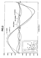
- Fig. 2 is a chart illustrating characteristic curves of 1st-order, 2nd-order, 3rd-order, 4th-order, and over-all vibration frequency components in a state that the center-of-gravity W of the lower link is located away from the center of the crankpin.
- Fig. 3 is a chart illustrating characteristic curves of 1st-order, 2nd-order, 3rd-order, 4th-order, and over-all vibration frequency components in a state that the center-of-gravity W is located near the center of the crankpin.
- Fig. 4 is a chart illustrating characteristic curves of 1st-order, 2nd-order, 3rd-order, 4th-order, and over-all vibration frequency components in a state that the center-of-gravity W is located to be identical to the center of the crankpin.
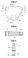
- Fig. 5 is an elevation view illustrating one structural shape of the lower link.
- Fig. 6 is a cross section taken along the line VI-VI of Fig. 5 .
- Fig. 7 is a cross section taken along the line VII-VII of Fig. 5 .
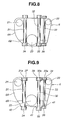
- Fig. 8 is a cross section of the lower link, showing one bolt arrangement for the lower link.
- Fig. 9 is a cross section of the lower link, showing another bolt arrangement for the lower link.
- Fig. 10 is a top view of the lower link shown in Fig. 9 .
- Fig. 11 is a cross section of the lower link, showing another bolt arrangement for the lower link.
- Fig. 12 is a perspective view illustrating the other structural shape of the lower link.
- Fig. 13 is an elevation view of the lower link of Fig. 12 .
- Fig. 14 is an explanatory view showing the layout of bolts used to integrally connect two split parts of the lower link of Fig. 12 .
- Fig. 15 is a top view showing the position relationship among the lower link, the upper link, and the control link.
- Fig. 16 is a diagram illustrating analytical mechanics for forces acting on the lower link and the division wall surface through which the lower link of Fig. 12 is divided into two parts.
- Fig. 17 is an explanatory view showing various dimensions, namely an inside diameter d1 of a first connecting pin hole, an inside diameter d2 of a second connecting pin hole, a distance L1 between the first connecting pin hole and the crankpin hole, and a distance L2 between the second connecting pin hole and the crankpin hole, and the magnitudes of applied forces f1, f2, and f3.
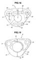
- Fig. 18 is an explanatory view showing the shortest distance L3 between the first connecting pin hole (for the connecting pin of the upper link) and the crankpin hole.
- Fig. 19 is an elevation view of the lower link having the division wall surface formed by way of cracking.
- the multiple-link type piston crank mechanism of the invention is constructed to function as a variable compression ratio mechanism.
- the linkage of the multiple-link type piston crank mechanism is comprised of three links, namely an upper link 3, a lower link 6, and a control link 9.
- Upper link 3 is connected at one end via a piston pin 2 to a reciprocating piston 1.
- Lower link 6 is oscillatingly connected to the other end of upper link 3 by means of a first connecting pin 7.
- Lower link 6 is also mechanically linked to a crankpin 5 of a crankshaft 4 .
- Control link 9 is oscillatingly connected at one end to lower link 6 by means of a second connecting pin 8.
- control link 9 is linked to a body (e.g., a cylinder block) of the engine, so as to restrict the degree of freedom of lower link 6.
- Piston 1 is slidable through a stroke in a cylinder (not shown) defined in a cylinder block (not shown).
- the piston crown of piston 1 defines a combustion chamber in conjunction with an inner wall surface of a cylinder head (not shown).
- the other end of control link 9 is oscillatingly or rockably supported by means of an eccentric cam portion 10A of a control shaft 10.
- Control shaft 10 is located at the lower part of the cylinder block.
- lower link 6 has a two-split structure. As shown in Figs. 1 and 5 , lower link 6 is divided into two parts, namely a main lower link portion 6A and a cap portion 6B, along a plane that passes through the center of crankpin 5, in other words, through the crankpin axis. When assembling, the main lower link portion and the cap portion are matched to each other by means of a fastening means, such as bolts and nuts. As clearly shown in Fig. 1 , lower link 6 is designed and dimensioned such that the center of crankpin 5, the center of first connecting pin 7, and the center of second connecting pin 8 are laid out at the respective vertexes of a triangle.
- the triangle is defined by three line segments, namely a first line segment between and including the center of crankpin 5 and the center of first connecting pin 7, a second line segment between and including the center of crankpin 5 and the center of second connecting pin 8, and a third line segment between and including the center of first connecting pin 7 and the center of second connecting pin 8.
- a so-called skeleton diagram indicated by the thick solid line of Fig. 1 represents each of the upper and lower links, the crank, and the control link included in the multiple-link type piston crank mechanism.
- a point denoted by W corresponds to a center of gravity of lower link 6.
- the center-of-gravity W exists or lies inside of the previously-noted triangle defined by three vertexes or apexes, namely the center of crankpin 5, the center of first connecting pin 7, and the center of second connecting pin 8.
- rc denotes the distance from the center-of-gravity W of lower link 6 to the center of crankpin 5
- r1 denotes the distance from the center-of-gravity W to the center of first connecting pin 7
- r2 denotes the distance from the center-of-gravity W to the center of second connecting pin 8.
- the position of center-of-gravity W is designed or determined to satisfy at least one of two conditions defined by a first inequality rc ⁇ r1 and a second inequality rc ⁇ r2.
- the position of center-of-gravity W is determined to satisfy the two conditions defined by the first inequality rc ⁇ r1 and the second inequality rc ⁇ r2. It is more preferable that the distance rc is "0", in other words, the center-of-gravity W of lower link 6 is situated to be identical to the center of crankpin 5.
- the center-of-gravity W of lower link 6 is determined by or derived from an equivalent inertia weight (W 0 +W 1 +W 2 +W 3 +W 4 ) of lower link 6 containing a weight W 1 of first connecting pin 7, a weight W 2 of second connecting pin 8, a weight W 3 of the lower boss-shaped end of upper link 3, and a weight W 4 of the upper boss-shaped end of control link 9.
- a center of gravity which is determined by or derived from only a self-weight W 0 of the lower link itself except the above-mentioned weights W 1 , W 2 , W 3 and W 4 , is arranged or laid out to be opposite to each of first and second connecting pins 7 and 8 with respect to the center of crankpin 5, that is, with respect to the crankpin axis used as a reference.
- lower link 6 The structural shape and dimensions of lower link 6 are designed or determined, so that the center-of-gravity W is situated near the center of crankpin 5 or situated to be identical to the center of crankpin 5, by actually adding the weights W 1 and W 2 of first and second connecting pins 7 and 8, the weight W 3 of the lower boss-shaped end of upper link 3, and the weight W 4 of the upper boss-shaped end of control link 9 to the self-weight W 0 of the lower link itself.
- the center of gravity of only the lower link member of the weight W 0 is determined so that the position of the center of gravity derived from the previously-noted equivalent inertia weight (W 0 +W 1 +W 2 +W 3 +W 4 ) is optimized or situated as close to the crankpin axis as possible in the actually assembled state.
- the fundamental shape, geometry and dimensions of lower link 6 of the embodiment are designed or determined to satisfy both the first inequality rc ⁇ r1 and the second inequality rc ⁇ r2.
- first connecting pin 7 is set to be higher than that of crankpin 5 at the midpoint of piston stroke at which the piston velocity reaches its peak. That is, lower link 6 serves as a swing lever that oscillates around second connecting pin 8. Actually, the second connecting pin serves as a fulcrum point of the lower link. The control link and the lower link are connected to each other via the second connecting pin to permit relative rotation. Thus, lower link 6 acts to transmit the motion of crankpin 5 to piston 1, while multiplying the displacement (motion) of crankpin 5. Therefore, in comparison with a radius of a crank of a typical reciprocating internal combustion engine with a piston crank mechanism and of the same engine's displacement, the crank radius of the reciprocating engine with the multiple-link type piston crank mechanism can be reduced or shortened.
- FIG. 2 through 4 there are shown first-order,second-order,third-order,fourth-order and over-all frequency characteristics of vibration occurring at themultiple-link type piston crank mechanism respectively depending upon the position of center-of-gravity W of lower link 6 relative to the center of crankpin 5.
- the center-of-gravity W of lower link 6 is situated greatly away from the center of crankpin 5.
- Fig. 3 Fig.
- FIG. 3 shows characteristic curves of 1st-order, 2nd-order, 3rd-order, 4th-order, and over-all vibration frequency components obtained when the center-of-gravity W of lower link 6 is situated near the center of crankpin 5.
- Fig. 4 shows characteristic curves of 1st-order, 2nd-order, 3rd-order, 4th-order, and over-all vibration frequency components obtained when the center-of-gravity W of lower link 6 is situated to be identical to the center of crankpin 5.
- Figs. 5, 6 and 7 show the detailed structural shape of lower link 6.
- lower link 6 is formed with a first pin hole 21 into which first connecting pin 7 is fitted, a second pin hole 22 into which second connecting pin 8 is fitted, and a third pin hole (a crankpin hole) 23 into which crankpin 5 is fitted.
- the lower link in order to attach lower link 6 to crankpin 5 on the crankshaft, the lower link must be divided into two parts along a plane passing through the crankpin axis.
- lower link 6 is divided into main lower link portion 6A and cap portion 6B along the plane passing through the center of third pin hole 23 (i.e., the crankpin axis).
- Main lower link portion 6A is formed with both of first and second pinholes 21 and 22.
- the combustion load is transmitted through upper link 3 and first connecting pin 7 to lower link 6, and then transmitted to crankpin 5.
- the combustion load can be transmitted mainly through the main lower link portion to the crankpin.
- first connecting pin 7 that directly receives the combustion load is dimensioned to be greater than that of second connecting pin 8 serving as the fulcrum point of oscillating motion or swinging motion of lower link 6, since the magnitude of the load acting on second connecting pin 8 is comparatively less than that of first connecting pin 7 directly receiving the combustion load.
- second connecting pin 8 can be downsized in diameter as much as possible.
- Downsizing the second connecting pin prevents or suppresses the center-of-gravity W (derived from the equivalent inertia weight (W 0 +W 1 +W 2 +W 3 +W 4 ) of lower link 6) frombeing situated away from the center of crankpin 5.
- W derived from the equivalent inertia weight (W 0 +W 1 +W 2 +W 3 +W 4 ) of lower link 6) frombeing situated away from the center of crankpin 5.
- W derived from the equivalent inertia weight (W 0 +W 1 +W 2 +W 3 +W 4 ) of lower link 6) frombeing situated away from the center of crankpin 5.
- a portion around second connecting pin hole 22 is comparatively thin-walled, while aportionaround first connecting pin hole 21 is comparatively thick-walled.
- the thickness of main lower link portion 6A changes gradually so that the peripheral portion around second pin hole 22 is continuously and smoothly connected with the peripheral portion around first pin hole 21.
- FIG. 7 shows the cutaway of lower link 6, having the crankpin hole 23 at its lower part and the two pinholes 21 and 22 at its upper part, along the vertical line VII-VII of Fig. 5 .
- a portion around crankpin 5 that is, a portion around crankpin hole 23
- a portion around first connecting pin 7 is comparatively thin-walled.
- the thickness of lower link 6 is thin-walled gradually from the peripheral portion around crankpin 5 towards the upper part of lower link 6.
- FIG. 8 there is shown the concrete installation structure of bolts (31, 32, 33) and nuts (34, 35, 36) used to integrally connect main lower link portion 6A and cap portion 6B.
- three bolts 31, 32 and 33 are used.
- a first bolt 31 of the three bolts is located between crankpin 5 and first connecting pin 7.
- the remaining two bolts, namely a second bolt 32 and a third bolt 33 are both located between crankpin 5 and second connecting pin 8, since the distance between crankpin 5 (i.e., third pin hole 23) and second connecting pin 8 (i.e., second pin hole 22) is relatively longer than that between crankpin 5 and first connecting pin 7.
- First and second bolts 31 and 32 laid out substantially symmetrically with respect to the axis of crankpin 5, have the same bolt diameter.
- Third bolt 33 located nearer to second connecting pin 8 is downsized in bolt diameter in comparison with second bolt 32 located nearer to crankpin 5.
- the center-of-gravity W can be situated near the center of crankpin 5, by relatively downsizing the diameter of third bolt 33 located away from crankpin 5 in comparison with the diameter of each of first and secondbolts 34 and 35 located close to crankpin 5.
- each of main lower link portion 6A and cap portion 6B is formed with three bolt holes (through openings) for the first, second, third bolts.
- first, second, and third bolts (31, 32, 33) are first inserted into upper opening ends of the respective bolt holes formed in main lower linkportion 6A. Then, the threaded ends of first, second, and third bolts (31, 32, 33) are further inserted into the respective boltholes formed in cap portion 6B. Thereafter, main lower link portion 6A and cap portion 6B are firmly connected or matched to each other by tightening each of nuts (34, 35, 36) mounted on the cap portion 6B and engaged with the respective threaded ends of bolts (31, 32, 33) to a specified tightening torque.
- each of headed portions (31a, 32a, 33a) of three bolts (31, 32, 33) is formed into a deformed shape or an elongated shape (such as an oval cross section, an elliptical cross section, or a rectangular cross section) that prevents the headed portion from rotating about its axis.
- a deformed shape or an elongated shape such as an oval cross section, an elliptical cross section, or a rectangular cross section
- each of headed portions (31a, 32a, 33a) is elongated in a direction perpendicular to the axial direction of crankshaft 4.
- main lower link portion 6A is formed in its upper end surface with recessed portions (37, 38, 39) respectively configured to be substantially conformable to the elongated shapes of headed portions (31a, 32a, 33a), such that the headed portions are fitted into the respective recessed portions.
- the dimension of each of recessed portions (37, 38, 39), measured in the axial direction of crankshaft 4 is relatively less than the dimension of each of recessed portions (37, 38, 39), measured in the direction normal to the axial direction of crankshaft 4.
- each of the seat portions is boss-shaped in such a manner as to slightly project from the bottom face of the cap portion.
- each of the seat portions (40, 41, 42) serves as a nut seat. In the bolt layout shown in Figs.
- each of headed portions (31a, 32a, 33a) can be installed as if the headed portions are buried in main lower link portion 6A, and simultaneously seat portions (40, 41, 42) are boss-shaped and projected downwards from the bottom face of cap portion 6B.
- the center-of-gravity W can be situated closer to the center of crankpin 5.
- Seat portions (40, 41, 42) formed on the bottom of cap portion 6B are useful to increase the distance (i.e., the wall thickness) between the inner peripheral wall surface (bearing surface) of third pin hole (crankpin hole) 23 and the bearing surface of each of the nuts.
- the provision of the seat portions (40, 41, 42) it is possible to enhance the mechanical strength, rigidity and durability of the lower link assembly.
- FIG. 11 there is shown another installation structure of bolts (31, 32, 33) used to integrally connect main lower link portion 6A and cap portion 6B.
- cap portion 6B is provided with three bolt holes (through openings), while main lower link portion 6A is provided with three female screw-threaded portions (43, 44, 45).
- three bolts (31, 32, 33) are first inserted into lower opening ends of the respective bolt holes formed in cap portion 6B. Then, the bolts are screwed into the respective female screw-threaded portions formed in main lower link portion 6A.
- Fig. 9 in the bolt layout shown in Fig.
- the cap portion 6B is formed with three boss-shaped seat portions (40, 41, 42) projected downwards from the bottom face of cap portion 6B.
- each of the seat portions (40, 41, 42) serves as a bolt seat.
- bolts (31, 32, 33) are located near the crankpin, and therefore the center-of-gravity W of lower link 6 can be effectively situated nearer the center of crankpin 5.
- Fig. 11 by further boring upward-extending through openings or further forming upward-extending threaded portions in the main lower link portion 6A continuously from the respective female threaded portions (43, 44, 45), it is possible to more effectively lighten the main lower link portion.
- Figs. 12 through 14 there is shown the other embodiment of lower link 6.
- the lower link shown in Figs. 12 - 14 is provided with first, second and third pin holes 21, 22 and 23.
- the first and second pinholes support the respective connecting pins 7 and 8.
- Crankpin 5 is linked into third pinhole 23.
- one end of upper link 3 and/or one end of control link 9 is constructed as a forked end.
- an intermediate rod portion being continuous with the forked end of at least one of upper link 3 and control link 9 tends to be thick-walled. This results in an increased weight of upper link 3 and/or control link 9.
- Such an increased weight of upper link 3 and/or control link 9 may result in undesirably amplified vibration frequency components.
- lower link 6 has two forked ends and thus the weight of the lower link itself tends to increase, while each of upper link 3 and control link 9 has no forked end and thus the weight of each of the upper link and the control link tends to decrease.
- the total weight of the multiple-link type piston crank mechanism can be reduced.
- the somewhat increased weight of lower link 6 generally acts to deteriorate the noise/vibration attenuation performance.
- it is possible to minimize the deterioration of the noise/vibration attenuation performance by properly setting the position of center-of-gravity W of lower link 6, that is, by setting the center-of-gravity W of lower link 6 as close to the center of crankpin 5 as possible.
- the lower-link upper left end in which first pin hole 21 is formed is actually constructed as a forked end.
- the forked end is composed of a pair of first arm portions or a pair of first boss-shaped portions (51, 51), each formed with through openings serving as the first pin hole, and a first recessed portion 52 defined between the first arm portions.
- the lower-link upper right end in which second pin hole 22 is formed is actually constructed as a forked end.
- the forked end is composed of a pair of second arm portions or a pair of second boss-shaped portions (53, 53), each formed with through openings serving as the second pin hole, and a second recessedportion 54 defined between the second arm port ions.
- both ends of first connecting pin 7 are supported by the first arm portions (51, 51), whereas both ends of second connecting pin 8 are supported by the second arm portions (53, 53).
- upper link 3 i.e., the upper-link lower end
- Control link 9 i.e., the control-link upper end
- second recessed portion 54 defined between second arm portions (53, 53)
- First connecting pin 7 is press-fitted to the lower boss-shaped end of upper link 3.
- second connecting pin 8 is rotatably supported by both second pinhole 22 of lower link 6 and a pinhole formed in the upper boss-shaped end of control link 9 via a bushing (not shown), in a full-float fashion.
- the bushing is used in order to attach lower link 6 and control link 9 with second connecting pin 8.
- the second connecting pin is not locked to either the lower link or the control link. This method is called "free floating".
- the second connecting pin 8 is free to rotate (float) on the inner peripheral wall defining the second pinhole and on the inner peripheral wall defining the pinhole formed in the control-link upper boss-shaped end. In the embodiment shown in Figs.
- lower link 6 is divided into two parts along the direction substantially normal to a straight line passing through both the center of first pin hole 21 and the center of second pin hole 22.
- the lower link is divided into a first lower link portion 6C (see the left-hand half of Figs. 13 and 14 ) including first pin hole 21 and a second lower link portion 6D (see the right-hand half of Figs. 13 and 14 ) including second pin hole 22 along a division wall surface 55 which consists of a plane passing through the center of third pin hole 23 (that is, the crankpin axis) and substantially normal to the straight line passing through both the center of first pin hole 21 and the center of second pin hole 22.
- Fig. 13 the lower link is divided into a first lower link portion 6C (see the left-hand half of Figs. 13 and 14 ) including first pin hole 21 and a second lower link portion 6D (see the right-hand half of Figs. 13 and 14 ) including second pin hole 22 along a division wall surface 55 which consists of a plane passing
- first and second lower link portions 6C and 6D are integrally connected to each other by tightening a pair of bolts (56, 56) located at both sides of third pin hole 23.
- second (right-hand) lower link portion 6D is provided with two bolt holes (two through openings), while first (left-hand) lower link portion 6C is provided with two female screw-threaded portions.
- the bolts (56, 56) are first inserted into opening ends of the respective boltholes formed in second lower link portion 6D. Then, the bolts are screwed into the respective female screw-threaded portions formed in first lower link portion 6C.
- the bolts are screwed into the respective female screw-threaded portions formed in first lower link portion 6C.
- the shape and dimensions of lower link 6 are designed or determined, so that the center-of-gravity W is situated near the center of crankpin 5 or situated to be identical to the center of crankpin 5, by adding the weights W 1 and W 2 of first and second connecting pins 7 and 8, the weight W 3 of the lower boss-shaped end of upper link 3, and the weight W 4 of the upper boss-shaped end of control link 9 to the self-weight W 0 of the lower link itself.
- Fig. 16 shows the directions of forces (tensile and compressive loads) applied to lower link 6 having a two-split structure shown in Figs. 12 - 14 .
- first and second connecting pins 7 and 8 are pushed down.
- a downward force f1 acts on the bearing surface of the first pinhole for first connecting pin 7
- a downward force f2 acts on the bearing surface of the second pinhole for second connecting pin 8.
- a reaction force (upward force) f3 acts on the bearing surface of the third pinhole for crankpin 5.
- Tensile forces act upon the peripheral portion around third pin hole 23, exactly the half-round portions of first and second lower link portions 6C and 6D. As clearly shown in Fig. 16 , the direction of action of each of the tensile forces is a direction parallel to the division wall surface 55.
- compressive forces act upon the inside mated portions of two-split lower link portions 6C and 6D, located inside of the intermediate portions of two bolts (56, 56) and close to the outer periphery of crankpin 5. The compressive forces serve to hold the mated state of first and second lower link portions 6C and 6D. In other words, there is less tensile load acting to open the division wall surface 55 at the previously noted inside mated portions.
- first lower link portion 6C In the absence of seat portions formed in first lower link portion 6C, the peripheral portion around first connecting pin 6C is strong enough to maintain rigidity and mechanical strength. Also, the construction of first lower link portion 6C equipped with first connecting pin 7 receiving great combustion and inertia loads is simplified. Thus, it is possible to avoid a concentration of stress between first connecting pin 7 and crankpin 5, and additionally it is possible to reduce the total weight of lower link 6.
- first connecting pin 7 and crankpin 5
- the distance L1 between the center of third pin hole 23 and the center of first pin hole 21 is less than the distance L2 between the center of third pin hole 23 and the center of second pin hole 22 (that is, L1 ⁇ L2), and the diameter d1 of first pin hole 21 is greater than the diameter d2 of second pin hole 22 (that is, d1 > d2) .
- the magnitude of downward force f1 acting on the bearing surface of first pinhole 21 is greater than the magnitude of downward force f2 acting on the bearing surface of second pinhole 22 (that is, f1 > f2).
- first connecting pin 7 is securely connected to the boss-shaped portion of upper link 3, and therefore it is possible to reduce the outside dimensions of the boss-shaped portion of upper link 3, while ensuring a required mechanical strength of the connecting portion between upper and lower links 3 and 6.
- first recessed portion 52 configured to be substantially conformable to the boss-shaped portion of upper link 3.
- By small-sizing the first recessed portion it is possible to set the shortest distance L3 between the bottom face (see the left-hand side broken line of Fig. 18 ) of first recessed portion 52 and the circumference of third pinhole 23 (i.e., the crankpin hole) to a comparatively great value.
- second connecting pin 8 is rotatably supported in a full-float fashion, as set forth above.
- the free-floating second connecting pin it is possible to set an allowable bearing stress at a higher level than the press-fitted first connecting pin. Therefore, it is possible to downsize the diameter of second connecting pin 8. As a result, it is possible to effectively reduce the entire weight of the lower link assembly including the second connecting pin.
- Fig. 19 shows one manufacturing process of division wall surface 55 between first and second lower link portions 6C and 6D.
- lower link 6 is temporarily formed as a cast lower-link product (a semi-finished product).
- the cast lower-link product has first and second lower link portions 6C and 6D integrally formed with each other.
- the cast lower-link product is broken into or cracked into or divided into two parts, namely first and second lower link portions 6C and 6D bywayof cracking.
- the lower link has a comparatively great division wall surface, and thus the previously noted cracking is a very effective manufacturing method for a lower link of a two-split structure. Furthermore, according to the manufacturing process of the two-split lower link as explained in reference to Fig. 19 , it is possible to enhance the circularity of third pinhole 23.
- a piston crank mechanism of a reciprocating internal combustion engine including a piston 1 moveable through a stroke in the engine and having a piston pin 2 and a crankshaft 4 changing reciprocating motion of the piston 1 into rotating motion and having a crankpin 5,
- the piston crank mechanism comprising: an upper link 3 connected at one end to the piston 1 via the piston pin 2; a lower link 6 connected to the other end of the upper link 3 via a first connecting pin 7 and connected to the crankpin; a control link 9 connected at one end to the lower link 6 via a second connecting pin 8 and pivoted at its other end to a body of the engine to permit oscillating motion of the control link 9 on the body of the engine; a center-of-gravity W of the lower link 6 lying inside of a triangle defined by three vertexes corresponding to a center of the first connecting pin 7, a center of the second connecting pin 8, and a center of the crankpin 5; and a distance rc from the center-of-gravity W to the center of the crank
- the distance rc from the center-of-gravity W to the center of the crankpin 5 is less than the distance r1 from the center-of-gravity W to the center of the first connecting pin 7, and the distance rc from the center-of-gravity W to the center of the crankpin 5 is less than the distance r2 from the center-of-gravity W to the center of the second connecting pin 8.
- the distance rc from the center-of-gravity W to the center of the crankpin 5 is 0.
- the center-of-gravity W is determined by a weight obtained by adding at least a weight W 1 of the first connecting pin 7 and a weight W 2 of the second connecting pin 8 to a self-weight W 0 of the lower link itself.
- the center-of-gravity W is determined by an equivalent inertia weight (W 0 +W 1 +W 2 +W 3 +W 4 ) obtained by further adding a weight W 3 of a boss-shaped end of the upper link 3 connected to the first connecting pin 7 and a weight W 4 of a boss-shaped end of the control link 9 connected to the second connecting pin 8 to the self-weight W 0 of the lower link 6 in addition to the weight W 1 of the first connecting pin 7 and the weight W 2 of the second connecting pin 8.
- a piston crank mechanism of a reciprocating internal combustion engine including a piston 1 moveable through a stroke in the engine and having a piston pin 2 and a crankshaft 4 changing reciprocating motion of the piston 1 into rotating motion and having a crankpin 5,
- the piston crank mechanism comprising: an upper link 3 connected at one end to the piston 1 via the piston pin 2; a lower link 6 connected to the other end of the upper link 3 via a first connecting pin 7 and connected to the crankpin; a control link 9 connected at one end to the lower link 6 via a second connecting pin 8 and pivoted at its other end to a body of the engine to permit oscillating motion of the control link 9 on the body of the engine;
- a triangle being defined by three line segments, namely a first line segment between and including a center of the crankpin 5 and a center of the first connecting pin 7, a second line segment between and including the center of the crankpin 5 and a center of the second connecting pin 8, and a third line segment between and including the center of the first connecting pin 7 and the center
- an angular velocity of the first connecting pin 7 is set to be higher than any velocity of the second connecting pin 8 at a midpoint of piston stroke at which a velocity of the piston 1 reaches its peak.
- an outside diameter of the first connecting pin 7 is dimensioned to be greater than an outside diameter of the second connecting pin 8.
- a thickness of a portion around the first connecting pin 7 of the lower link 6 is dimensioned to be greater than a thickness of a portion around the second connecting pin 8.
- a thickness of a portion around the crankpin 5 of the lower link 6 is dimensioned to be greater than a thickness of a portion around the first connecting pin 7.
- the lower link 6 is divided into a main lower link portion 6A including the first and second connecting pins 7, 8 and a cap portion 6B along a plane that passes through the center of the crankpin 5; the main lower link portion 6A and the cap portion 6B are integrally connected to each other by a plurality of bolts 31, 32, 33 located on both sides of the crankpin 5 ; and an axis of a first bolt of the plurality of bolts passes between the crankpin 5 and the first connecting pin 7, and an axis of a second bolt of the plurality of bolts passes between the crankpin 5 and the second connecting pin 8.
- an axis of a third bolt 33 of the plurality of bolts passes between the crankpin 5 and the second connecting pin 8; and the third bolt 33 located nearer to the second connecting pin 8 is downsized in bolt diameter in comparison with the second bolt 32 located nearer to the crankpin 5.
- each of the main lower link portion 6A and the cap portion 6B is formed with a plurality of bolt holes for the plurality of bolts 31, 32, 33; and threaded ends of the bolts 31, 32, 33 inserted through the bolt holes of the main lower link portion 6A into the bolt holes of the cap portion 6B are threadably engaged with nuts 34, 35, 36 mounted outside of the cap portion 6B.
- the main lower link portion 6A is formed with a plurality of recessed portions 37, 38, 39 accommodating therein respective headed portions 31a, 32a, 33a of the bolts 31, 32, 33.
- the recessed portions 37, 38, 39 are respectively configured to be substantially conformable to shapes of the headed portions 31a, 32a, 33a of the bolts 31, 32, 33; and each of the recessed portions 37, 38, 39 is formed into an elongated shape that a dimension measured in an axial direction of the crankshaft 4 is relatively smaller than a dimension measured in a direction normal to the axial direction of the crankshaft 4.
- the cap portion 6B is formed with a plurality of bolt holes for the plurality of bolts 31, 32, 33, and the main lower link portion 6B is formed with a plurality of female screw-threaded portions 43, 44, 45 for threaded-engagement with the bolts 31, 32, 33; and threaded portions of the bolts 31, 32, 33 inserted through the bolt holes of the cap portion 6B are screwed into the female screw-threaded portions 43, 44, 45.
- the cap portion 6B is formed with seat portions 40, 41, 42 on which the bolts 31, 32, 33 or the nuts 34, 35, 36 are seated, so that each of the seat portions is boss-shaped and projected from a face of the cap portion.
- a connected portion of the lower link 6 to the upper link 3 is formed as a first forked end comprising a first pair of boss-shaped portions 51, 51
- a connected portion of the lower link 6 to the control link 9 is formed as a second forked end comprising a second pair of boss-shaped portions 53, 53; both ends of the first connecting pin 7 are supported by the first pair of boss-shaped portions 51, 51, and both ends of the second connecting pin 8 are supported by the second pair of boss-shaped portions 53, 53; and the upper link 3 sandwiched between the first pair of boss-shaped portions 51, 51 is oscillatingly pinned to the lower link 6 through the first connecting pin 7, and the control link 9 sandwiched between the second pair of boss-shaped portions 53, 53 is oscillatingly pinned to the lower link 6 through the second connecting pin 8.
- first connecting pin 7 is press-fitted into a boss-shaped portion of the upper link 3, and the second connecting pin 8 is rotatably connected to both the lower link 6 and the control link 9 by free floating.
- the lower link 6 is divided into a first lower link portion 6C including the first connecting pin 7 and a second lower link portion 6D including the second connecting pin 8 along a division wall surface 55 consisting of a plane passing through the center of the crankpin 5.
- the secondlower linkportion 6D is formed with a plurality of bolt holes for a plurality of bolts 56, 56
- the first lower link portion 6C is formed with a plurality of female screw-threaded portions for threaded-engagement with the bolts 56, 56; and threaded portions of the bolts 56, 56 inserted through the bolt holes of the second lower link portion 6D are screwed into the female screw-threaded portions formed in the first lower link portion 6C to integrally connect the first and second lower link portions 6C, 6D to each other.
- the division wall surface 55 between the first and second lower link portions (6C, 6D) is formed as a cracked section by way of cracking.
Applications Claiming Priority (3)
| Application Number | Priority Date | Filing Date | Title |
|---|---|---|---|
| JP2000245448 | 2000-08-14 | ||
| JP2000316020A JP3861583B2 (ja) | 2000-08-14 | 2000-10-17 | 内燃機関のピストンクランク機構 |
| EP01119056A EP1180588B1 (de) | 2000-08-14 | 2001-08-07 | Kolben-Kurbelmechanismus für eine Brennkraftmaschine |
Related Parent Applications (2)
| Application Number | Title | Priority Date | Filing Date |
|---|---|---|---|
| EP01119056A Division EP1180588B1 (de) | 2000-08-14 | 2001-08-07 | Kolben-Kurbelmechanismus für eine Brennkraftmaschine |
| EP01119056.8 Division | 2001-08-07 |
Publications (3)
| Publication Number | Publication Date |
|---|---|
| EP1914405A2 true EP1914405A2 (de) | 2008-04-23 |
| EP1914405A3 EP1914405A3 (de) | 2011-08-17 |
| EP1914405B1 EP1914405B1 (de) | 2014-05-21 |
Family
ID=26597920
Family Applications (2)
| Application Number | Title | Priority Date | Filing Date |
|---|---|---|---|
| EP07024539.4A Expired - Lifetime EP1914405B1 (de) | 2000-08-14 | 2001-08-07 | Kurbelmechanismus für einen Kolben-Verbrennungsmotor |
| EP01119056A Expired - Lifetime EP1180588B1 (de) | 2000-08-14 | 2001-08-07 | Kolben-Kurbelmechanismus für eine Brennkraftmaschine |
Family Applications After (1)
| Application Number | Title | Priority Date | Filing Date |
|---|---|---|---|
| EP01119056A Expired - Lifetime EP1180588B1 (de) | 2000-08-14 | 2001-08-07 | Kolben-Kurbelmechanismus für eine Brennkraftmaschine |
Country Status (4)
| Country | Link |
|---|---|
| US (1) | US6622670B2 (de) |
| EP (2) | EP1914405B1 (de) |
| JP (1) | JP3861583B2 (de) |
| DE (1) | DE60134367D1 (de) |
Cited By (4)
| Publication number | Priority date | Publication date | Assignee | Title |
|---|---|---|---|---|
| DE102011116609A1 (de) * | 2011-10-21 | 2013-04-25 | Audi Ag | Mehrgelenkskurbeltrieb |
| DE102013021980A1 (de) * | 2013-12-20 | 2015-06-25 | Audi Ag | Koppelglied für einen Mehrgelenkskurbeltrieb sowie Mehrgelenkskurbeltrieb |
| CN110159426A (zh) * | 2019-06-28 | 2019-08-23 | 长城汽车股份有限公司 | 发动机的装配方法以及发动机 |
| DE102010004578B4 (de) * | 2010-01-14 | 2019-11-07 | Audi Ag | Brennkraftmaschine mit Mehrgelenkskurbeltrieb sowie in Schwenkgelenken des Kurbeltriebs schwimmend gelagerten Bolzen |
Families Citing this family (41)
| Publication number | Priority date | Publication date | Assignee | Title |
|---|---|---|---|---|
| JP4654514B2 (ja) * | 2000-12-26 | 2011-03-23 | 日産自動車株式会社 | レシプロ式内燃機関のピストンクランク機構 |
| JP2003314211A (ja) * | 2002-04-17 | 2003-11-06 | Honda Motor Co Ltd | ストローク可変エンジン |
| JP4300749B2 (ja) * | 2002-05-09 | 2009-07-22 | 日産自動車株式会社 | レシプロ式内燃機関のリンク機構 |
| US7191741B2 (en) | 2002-12-16 | 2007-03-20 | Nissan Motor Co., Ltd. | Pin connected link mechanism |
| JP4148046B2 (ja) | 2003-07-08 | 2008-09-10 | 日産自動車株式会社 | 内燃機関のピストンクランク機構におけるロアリンク |
| JP4092495B2 (ja) * | 2003-08-28 | 2008-05-28 | 日産自動車株式会社 | 内燃機関の複リンク式ピストン−クランク機構 |
| JP4148144B2 (ja) * | 2004-01-22 | 2008-09-10 | トヨタ自動車株式会社 | 近似直線機構を有するピストン機関 |
| JP2005344530A (ja) | 2004-06-01 | 2005-12-15 | Nissan Motor Co Ltd | 内燃機関 |
| JP4506340B2 (ja) * | 2004-08-03 | 2010-07-21 | 日産自動車株式会社 | 内燃機関のピストンクランク機構におけるロアリンク |
| JP4613607B2 (ja) * | 2004-12-24 | 2011-01-19 | 日産自動車株式会社 | 内燃機関のピストンクランク機構におけるロアリンク |
| FR2881513B1 (fr) * | 2005-02-03 | 2007-04-06 | Sagem | Machine a froid fonctionnant suivant le cycle de stirling |
| JP2007064013A (ja) * | 2005-08-29 | 2007-03-15 | Honda Motor Co Ltd | ストローク可変エンジン |
| DE102005054760A1 (de) * | 2005-11-17 | 2007-05-31 | Daimlerchrysler Ag | Hubkolbenbrennkraftmaschine mit veränderlichem Verdichtungsverhältnis |
| DE102005054761A1 (de) * | 2005-11-17 | 2007-05-31 | Daimlerchrysler Ag | Brennkraftmaschine |
| JP4779635B2 (ja) | 2005-12-20 | 2011-09-28 | 日産自動車株式会社 | 内燃機関のピストンクランク機構におけるロアリンク |
| JP2007232112A (ja) * | 2006-03-02 | 2007-09-13 | Nissan Motor Co Ltd | 複リンク式ピストンクランク機構の軸受構造 |
| JP4984574B2 (ja) * | 2006-03-03 | 2012-07-25 | 日産自動車株式会社 | ピストンクランク機構のクランクシャフト |
| JP2008075611A (ja) * | 2006-09-25 | 2008-04-03 | Honda Motor Co Ltd | ストローク特性可変エンジン |
| EP1965051B1 (de) | 2006-09-12 | 2016-01-06 | Honda Motor Co., Ltd. | Motoranordnung mit variablen hubeigenschaften |
| JP4882912B2 (ja) * | 2007-08-10 | 2012-02-22 | 日産自動車株式会社 | 可変圧縮比内燃機関 |
| JP4922122B2 (ja) * | 2007-10-11 | 2012-04-25 | 本田技研工業株式会社 | ストローク可変エンジン |
| JP4922121B2 (ja) * | 2007-10-11 | 2012-04-25 | 本田技研工業株式会社 | ストローク可変エンジン |
| US8100097B2 (en) * | 2007-10-26 | 2012-01-24 | Nissan Motor Co., Ltd. | Multi-link engine |
| US7891334B2 (en) * | 2008-07-17 | 2011-02-22 | O'leary Paul W | Engine with variable length connecting rod |
| JP5146250B2 (ja) * | 2008-10-20 | 2013-02-20 | 日産自動車株式会社 | 複リンク式エンジンの振動低減構造 |
| JP5126100B2 (ja) * | 2009-02-10 | 2013-01-23 | 日産自動車株式会社 | 複リンク機構 |
| DE102011017212A1 (de) | 2011-04-15 | 2012-10-18 | Daimler Ag | Kurbeltrieb für eine wenigstens ein variabel einstellbares Verdichtungsverhältnis aufweisende Hubkolbenmaschine |
| DE102011115247A1 (de) | 2011-06-21 | 2012-12-27 | Daimler Ag | Hebelelement für eine Stelleinrichtung zum variablen Einstellen eines Verdichtungsverhältnisses einer Verbrennungskraftmaschine sowie Verbrennungskraftmaschine mit wenigstens einem variabel einstellbaren Verdichtungsverhältnis |
| JP5273264B2 (ja) * | 2012-02-03 | 2013-08-28 | 日産自動車株式会社 | 内燃機関のピストンクランク機構におけるロアリンク |
| DE102012007465B4 (de) * | 2012-04-13 | 2014-09-11 | Audi Ag | Brennkraftmaschine |
| JP5327361B2 (ja) * | 2012-06-13 | 2013-10-30 | 日産自動車株式会社 | 複リンク式エンジンの振動低減構造 |
| DE102014002368B4 (de) | 2013-11-14 | 2015-11-12 | Audi Ag | Mehrgelenkskurbeltrieb einer Brennkraftmaschine sowie entsprechende Brennkraftmaschine |
| DE102014002022B4 (de) * | 2014-02-14 | 2018-03-01 | Audi Ag | Mehrgelenkskurbeltrieb einer Brennkraftmaschine sowie entsprechende Brennkraftmaschine |
| JP6241367B2 (ja) * | 2014-05-23 | 2017-12-06 | 日産自動車株式会社 | 複リンク式ピストンクランク機構におけるリンク連結構造およびリンク連結方法 |
| DE102015007135A1 (de) | 2015-06-05 | 2016-12-08 | Daimler Ag | Triebwerk für eine Hubkolben-Verbrennungsmaschine, insbesondere eines Kraftwagens |
| US10125679B2 (en) * | 2016-03-29 | 2018-11-13 | GM Global Technology Operations LLC | Independent compression and expansion ratio engine with variable compression ratio |
| GB2550321A (en) * | 2016-04-01 | 2017-11-22 | Yan Engines Ltd | Guide cam assembly for differential and variable stroke cycle engines |
| GB2550320A (en) * | 2016-04-01 | 2017-11-22 | Yan Engines Ltd | Movable fulcrum for differential and variable-stroke cycle engines |
| CN110671196B (zh) * | 2018-12-29 | 2021-07-20 | 长城汽车股份有限公司 | 发动机 |
| CN110285136A (zh) * | 2019-06-28 | 2019-09-27 | 长城汽车股份有限公司 | 下连杆和具有它的发动机 |
| CN113494512A (zh) * | 2020-04-08 | 2021-10-12 | 长城汽车股份有限公司 | 发动机的连杆组件、发动机以及车辆 |
Citations (2)
| Publication number | Priority date | Publication date | Assignee | Title |
|---|---|---|---|---|
| US4517931A (en) | 1983-06-30 | 1985-05-21 | Nelson Carl D | Variable stroke engine |
| JPH09228858A (ja) | 1996-02-24 | 1997-09-02 | Hondou Jutaku:Kk | レシプロエンジン |
Family Cites Families (6)
| Publication number | Priority date | Publication date | Assignee | Title |
|---|---|---|---|---|
| DE612405C (de) * | 1932-04-06 | 1935-04-24 | Edmund Bauer | Zweitaktverbrennungskraftmaschine |
| US3633429A (en) * | 1970-06-08 | 1972-01-11 | Thorvald N Olson | Piston stroke control mechanism |
| US6125802A (en) * | 1998-05-20 | 2000-10-03 | Pen; Pao Chi | Piston engine powertrain |
| JP2000073804A (ja) * | 1998-09-01 | 2000-03-07 | Toyota Autom Loom Works Ltd | 内燃機関及びその制御装置 |
| DE29913107U1 (de) * | 1999-07-27 | 1999-10-07 | Fend Fritz | Verbrennungsmotor |
| JP2001227367A (ja) * | 2000-02-16 | 2001-08-24 | Nissan Motor Co Ltd | レシプロ式内燃機関 |
-
2000
- 2000-10-17 JP JP2000316020A patent/JP3861583B2/ja not_active Expired - Lifetime
-
2001
- 2001-08-07 EP EP07024539.4A patent/EP1914405B1/de not_active Expired - Lifetime
- 2001-08-07 EP EP01119056A patent/EP1180588B1/de not_active Expired - Lifetime
- 2001-08-07 DE DE60134367T patent/DE60134367D1/de not_active Expired - Lifetime
- 2001-08-13 US US09/927,330 patent/US6622670B2/en not_active Expired - Lifetime
Patent Citations (2)
| Publication number | Priority date | Publication date | Assignee | Title |
|---|---|---|---|---|
| US4517931A (en) | 1983-06-30 | 1985-05-21 | Nelson Carl D | Variable stroke engine |
| JPH09228858A (ja) | 1996-02-24 | 1997-09-02 | Hondou Jutaku:Kk | レシプロエンジン |
Cited By (8)
| Publication number | Priority date | Publication date | Assignee | Title |
|---|---|---|---|---|
| DE102010004578B4 (de) * | 2010-01-14 | 2019-11-07 | Audi Ag | Brennkraftmaschine mit Mehrgelenkskurbeltrieb sowie in Schwenkgelenken des Kurbeltriebs schwimmend gelagerten Bolzen |
| DE102011116609A1 (de) * | 2011-10-21 | 2013-04-25 | Audi Ag | Mehrgelenkskurbeltrieb |
| DE102011116609B4 (de) * | 2011-10-21 | 2015-02-19 | Audi Ag | Mehrgelenkskurbeltrieb |
| DE102013021980A1 (de) * | 2013-12-20 | 2015-06-25 | Audi Ag | Koppelglied für einen Mehrgelenkskurbeltrieb sowie Mehrgelenkskurbeltrieb |
| WO2015090605A1 (de) | 2013-12-20 | 2015-06-25 | Audi Ag | Koppelglied für einen mehrgelenkskurbeltrieb sowie mehrgelenkskurbeltrieb |
| US9995335B2 (en) | 2013-12-20 | 2018-06-12 | Audi Ag | Coupling element for a multi-joint crank drive and multi-joint crank drive |
| CN110159426A (zh) * | 2019-06-28 | 2019-08-23 | 长城汽车股份有限公司 | 发动机的装配方法以及发动机 |
| CN110159426B (zh) * | 2019-06-28 | 2021-04-20 | 长城汽车股份有限公司 | 发动机的装配方法以及发动机 |
Also Published As
| Publication number | Publication date |
|---|---|
| DE60134367D1 (de) | 2008-07-24 |
| US6622670B2 (en) | 2003-09-23 |
| EP1914405A3 (de) | 2011-08-17 |
| JP3861583B2 (ja) | 2006-12-20 |
| EP1180588B1 (de) | 2008-06-11 |
| EP1180588A2 (de) | 2002-02-20 |
| EP1180588A3 (de) | 2003-04-02 |
| JP2002129995A (ja) | 2002-05-09 |
| EP1914405B1 (de) | 2014-05-21 |
| US20020026910A1 (en) | 2002-03-07 |
Similar Documents
| Publication | Publication Date | Title |
|---|---|---|
| EP1914405B1 (de) | Kurbelmechanismus für einen Kolben-Verbrennungsmotor | |
| EP1154134B1 (de) | Brennkraftmaschine mit variablem Verdichtungsverhältnis | |
| EP1126144B1 (de) | Kolbenbrennkraftmaschine | |
| US6684828B2 (en) | Variable compression ratio mechanism for reciprocating internal combustion engine | |
| EP2119899A1 (de) | Lagerstruktur für kurbelwelle | |
| EP1798396B1 (de) | Brennkraftmaschine | |
| JP4730152B2 (ja) | 内燃機関のピストンクランク機構におけるロアリンク | |
| JP4387770B2 (ja) | 内燃機関 | |
| EP2021584B1 (de) | Verbrennungsmotor | |
| US20030209219A1 (en) | Engine connecting rod mechanism for cylinder pressure control | |
| US20030209212A1 (en) | Variable compression ratio engine | |
| JP2008064010A (ja) | 可変圧縮比内燃機関 | |
| JP2004124775A (ja) | 内燃機関の可変圧縮比機構 | |
| JP4380321B2 (ja) | 内燃機関のピストンクランク機構におけるロアリンク | |
| JP4506340B2 (ja) | 内燃機関のピストンクランク機構におけるロアリンク | |
| JP4924583B2 (ja) | 可変圧縮比内燃機関 | |
| EP3763925A1 (de) | Brennkraftmaschine mit variablem verdichtungsverhältnis | |
| JP2002195001A (ja) | レシプロ式内燃機関のピストンクランク機構 | |
| JP2002155921A (ja) | 内燃機関のリンクロッド | |
| JP2010203345A (ja) | 複リンク式内燃機関の軸受構造 | |
| JP2003097288A (ja) | 内燃機関の可変圧縮比機構 | |
| JPH0828543A (ja) | ピストンクランク連接棒 | |
| JP2006046615A (ja) | 内燃機関のピストンクランク機構におけるロアリンク | |
| JP2006183479A (ja) | 内燃機関 | |
| JPH07243433A (ja) | コネクティングロッド |
Legal Events
| Date | Code | Title | Description |
|---|---|---|---|
| PUAI | Public reference made under article 153(3) epc to a published international application that has entered the european phase |
Free format text: ORIGINAL CODE: 0009012 |
|
| AC | Divisional application: reference to earlier application |
Ref document number: 1180588 Country of ref document: EP Kind code of ref document: P |
|
| AK | Designated contracting states |
Kind code of ref document: A2 Designated state(s): DE FR GB |
|
| RIN1 | Information on inventor provided before grant (corrected) |
Inventor name: AOYAMA, SHUNICHI Inventor name: HIYOSHI, RYOSUKE,C/O INTELLECTUAL PROPERTY OF NISS |
|
| PUAL | Search report despatched |
Free format text: ORIGINAL CODE: 0009013 |
|
| AK | Designated contracting states |
Kind code of ref document: A3 Designated state(s): DE FR GB |
|
| RIC1 | Information provided on ipc code assigned before grant |
Ipc: F02B 75/04 20060101ALI20110708BHEP Ipc: F01B 9/02 20060101ALI20110708BHEP Ipc: F02B 41/04 20060101ALI20110708BHEP Ipc: F02B 75/32 20060101AFI20110708BHEP |
|
| 17P | Request for examination filed |
Effective date: 20110929 |
|
| AKX | Designation fees paid |
Designated state(s): DE FR GB |
|
| GRAP | Despatch of communication of intention to grant a patent |
Free format text: ORIGINAL CODE: EPIDOSNIGR1 |
|
| INTG | Intention to grant announced |
Effective date: 20140225 |
|
| GRAS | Grant fee paid |
Free format text: ORIGINAL CODE: EPIDOSNIGR3 |
|
| GRAA | (expected) grant |
Free format text: ORIGINAL CODE: 0009210 |
|
| AC | Divisional application: reference to earlier application |
Ref document number: 1180588 Country of ref document: EP Kind code of ref document: P |
|
| AK | Designated contracting states |
Kind code of ref document: B1 Designated state(s): DE FR GB |
|
| REG | Reference to a national code |
Ref country code: GB Ref legal event code: FG4D |
|
| REG | Reference to a national code |
Ref country code: DE Ref legal event code: R096 Ref document number: 60148819 Country of ref document: DE Effective date: 20140703 |
|
| REG | Reference to a national code |
Ref country code: DE Ref legal event code: R097 Ref document number: 60148819 Country of ref document: DE |
|
| PLBE | No opposition filed within time limit |
Free format text: ORIGINAL CODE: 0009261 |
|
| STAA | Information on the status of an ep patent application or granted ep patent |
Free format text: STATUS: NO OPPOSITION FILED WITHIN TIME LIMIT |
|
| 26N | No opposition filed |
Effective date: 20150224 |
|
| REG | Reference to a national code |
Ref country code: DE Ref legal event code: R097 Ref document number: 60148819 Country of ref document: DE Effective date: 20150224 |
|
| REG | Reference to a national code |
Ref country code: FR Ref legal event code: PLFP Year of fee payment: 16 |
|
| REG | Reference to a national code |
Ref country code: FR Ref legal event code: PLFP Year of fee payment: 17 |
|
| REG | Reference to a national code |
Ref country code: FR Ref legal event code: PLFP Year of fee payment: 18 |
|
| PGFP | Annual fee paid to national office [announced via postgrant information from national office to epo] |
Ref country code: DE Payment date: 20200729 Year of fee payment: 20 Ref country code: FR Payment date: 20200715 Year of fee payment: 20 Ref country code: GB Payment date: 20200729 Year of fee payment: 20 |
|
| REG | Reference to a national code |
Ref country code: DE Ref legal event code: R071 Ref document number: 60148819 Country of ref document: DE |
|
| REG | Reference to a national code |
Ref country code: GB Ref legal event code: PE20 Expiry date: 20210806 |
|
| PG25 | Lapsed in a contracting state [announced via postgrant information from national office to epo] |
Ref country code: GB Free format text: LAPSE BECAUSE OF EXPIRATION OF PROTECTION Effective date: 20210806 |