EP1907124B2 - Apparatus for separation of particles from a flow of gas - Google Patents
Apparatus for separation of particles from a flow of gas Download PDFInfo
- Publication number
- EP1907124B2 EP1907124B2 EP06748058.2A EP06748058A EP1907124B2 EP 1907124 B2 EP1907124 B2 EP 1907124B2 EP 06748058 A EP06748058 A EP 06748058A EP 1907124 B2 EP1907124 B2 EP 1907124B2
- Authority
- EP
- European Patent Office
- Prior art keywords
- rotor
- particles
- gas
- flow
- surface elements
- Prior art date
- Legal status (The legal status is an assumption and is not a legal conclusion. Google has not performed a legal analysis and makes no representation as to the accuracy of the status listed.)
- Active
Links
- 239000002245 particle Substances 0.000 title claims description 88
- 238000000926 separation method Methods 0.000 title claims description 24
- 238000004062 sedimentation Methods 0.000 claims description 18
- 239000002344 surface layer Substances 0.000 claims description 18
- 230000002301 combined effect Effects 0.000 claims description 6
- 230000005684 electric field Effects 0.000 claims description 5
- 239000010410 layer Substances 0.000 claims description 4
- 238000005119 centrifugation Methods 0.000 claims 2
- 239000007789 gas Substances 0.000 description 46
- 238000009825 accumulation Methods 0.000 description 7
- 230000035508 accumulation Effects 0.000 description 7
- 230000000694 effects Effects 0.000 description 4
- 238000011144 upstream manufacturing Methods 0.000 description 4
- 238000011010 flushing procedure Methods 0.000 description 3
- 230000001105 regulatory effect Effects 0.000 description 3
- 238000004140 cleaning Methods 0.000 description 2
- 239000007788 liquid Substances 0.000 description 2
- 238000000034 method Methods 0.000 description 2
- 238000010276 construction Methods 0.000 description 1
- 238000000151 deposition Methods 0.000 description 1
- 239000000428 dust Substances 0.000 description 1
- 230000005686 electrostatic field Effects 0.000 description 1
- 239000010419 fine particle Substances 0.000 description 1
- 239000012634 fragment Substances 0.000 description 1
- 230000005484 gravity Effects 0.000 description 1
- 239000000463 material Substances 0.000 description 1
- 239000012811 non-conductive material Substances 0.000 description 1
- 239000007787 solid Substances 0.000 description 1
- 125000006850 spacer group Chemical group 0.000 description 1
Images


Classifications
-
- B—PERFORMING OPERATIONS; TRANSPORTING
- B03—SEPARATION OF SOLID MATERIALS USING LIQUIDS OR USING PNEUMATIC TABLES OR JIGS; MAGNETIC OR ELECTROSTATIC SEPARATION OF SOLID MATERIALS FROM SOLID MATERIALS OR FLUIDS; SEPARATION BY HIGH-VOLTAGE ELECTRIC FIELDS
- B03C—MAGNETIC OR ELECTROSTATIC SEPARATION OF SOLID MATERIALS FROM SOLID MATERIALS OR FLUIDS; SEPARATION BY HIGH-VOLTAGE ELECTRIC FIELDS
- B03C3/00—Separating dispersed particles from gases or vapour, e.g. air, by electrostatic effect
- B03C3/02—Plant or installations having external electricity supply
- B03C3/04—Plant or installations having external electricity supply dry type
- B03C3/14—Plant or installations having external electricity supply dry type characterised by the additional use of mechanical effects, e.g. gravity
- B03C3/15—Centrifugal forces
-
- B—PERFORMING OPERATIONS; TRANSPORTING
- B01—PHYSICAL OR CHEMICAL PROCESSES OR APPARATUS IN GENERAL
- B01D—SEPARATION
- B01D45/00—Separating dispersed particles from gases or vapours by gravity, inertia, or centrifugal forces
- B01D45/12—Separating dispersed particles from gases or vapours by gravity, inertia, or centrifugal forces by centrifugal forces
- B01D45/14—Separating dispersed particles from gases or vapours by gravity, inertia, or centrifugal forces by centrifugal forces generated by rotating vanes, discs, drums or brushes
-
- B—PERFORMING OPERATIONS; TRANSPORTING
- B03—SEPARATION OF SOLID MATERIALS USING LIQUIDS OR USING PNEUMATIC TABLES OR JIGS; MAGNETIC OR ELECTROSTATIC SEPARATION OF SOLID MATERIALS FROM SOLID MATERIALS OR FLUIDS; SEPARATION BY HIGH-VOLTAGE ELECTRIC FIELDS
- B03C—MAGNETIC OR ELECTROSTATIC SEPARATION OF SOLID MATERIALS FROM SOLID MATERIALS OR FLUIDS; SEPARATION BY HIGH-VOLTAGE ELECTRIC FIELDS
- B03C3/00—Separating dispersed particles from gases or vapour, e.g. air, by electrostatic effect
- B03C3/017—Combinations of electrostatic separation with other processes, not otherwise provided for
-
- B—PERFORMING OPERATIONS; TRANSPORTING
- B03—SEPARATION OF SOLID MATERIALS USING LIQUIDS OR USING PNEUMATIC TABLES OR JIGS; MAGNETIC OR ELECTROSTATIC SEPARATION OF SOLID MATERIALS FROM SOLID MATERIALS OR FLUIDS; SEPARATION BY HIGH-VOLTAGE ELECTRIC FIELDS
- B03C—MAGNETIC OR ELECTROSTATIC SEPARATION OF SOLID MATERIALS FROM SOLID MATERIALS OR FLUIDS; SEPARATION BY HIGH-VOLTAGE ELECTRIC FIELDS
- B03C3/00—Separating dispersed particles from gases or vapour, e.g. air, by electrostatic effect
- B03C3/34—Constructional details or accessories or operation thereof
- B03C3/36—Controlling flow of gases or vapour
- B03C3/361—Controlling flow of gases or vapour by static mechanical means, e.g. deflector
- B03C3/366—Controlling flow of gases or vapour by static mechanical means, e.g. deflector located in the filter, e.g. special shape of the electrodes
-
- B—PERFORMING OPERATIONS; TRANSPORTING
- B04—CENTRIFUGAL APPARATUS OR MACHINES FOR CARRYING-OUT PHYSICAL OR CHEMICAL PROCESSES
- B04B—CENTRIFUGES
- B04B5/00—Other centrifuges
- B04B5/10—Centrifuges combined with other apparatus, e.g. electrostatic separators; Sets or systems of several centrifuges
-
- B—PERFORMING OPERATIONS; TRANSPORTING
- B04—CENTRIFUGAL APPARATUS OR MACHINES FOR CARRYING-OUT PHYSICAL OR CHEMICAL PROCESSES
- B04B—CENTRIFUGES
- B04B5/00—Other centrifuges
- B04B5/12—Centrifuges in which rotors other than bowls generate centrifugal effects in stationary containers
-
- B—PERFORMING OPERATIONS; TRANSPORTING
- B04—CENTRIFUGAL APPARATUS OR MACHINES FOR CARRYING-OUT PHYSICAL OR CHEMICAL PROCESSES
- B04B—CENTRIFUGES
- B04B5/00—Other centrifuges
- B04B5/12—Centrifuges in which rotors other than bowls generate centrifugal effects in stationary containers
- B04B2005/125—Centrifuges in which rotors other than bowls generate centrifugal effects in stationary containers the rotors comprising separating walls
Definitions
- the present invention refers to an apparatus for the separation of particles from a flow of gas. More specifically, the invention relates to an apparatus for the separation of both very small, light particles and also larger, heavier particles from flows of gas.
- centrifugal separators for cleaning gases containing particles, such as oil particles, dust, etc.
- the separator comprises a rotor mounted in a stationary casing in such a way that it can rotate, with a stack of surface elements in the form of, for example, conical sedimentation plates (insert plates).
- separators of this type are effective for the separation of particles within a wide range of particle sizes. This is due to the short sedimentation distances between the plate elements and the high centrifugal forces. This type of separator is suitable for handling large quantities of particles.
- electrostatic filters or cleaners can be used, which, however, have limitations when it is a question of separating larger particles and handling larger quantities of particles.
- JP 2078454 discloses a centrifugal electrostatic oil cleaner having a plurality of conical separation discs, where a different polarity is applied to the discs and the surrounding rotary oil tank. This cleaner is not configured to generate an electrostatic field between the adjacent disc elements.
- An object of the present invention is to propose an apparatus for concurrent separation of particles from a flow of gas that improves the efficiency and capacity when separating off both large, heavy particles and also very small, light particles, either individually or in combination.
- this can be achieve according to the invention by means of an apparatus as defined in claim 1.
- extremely small and light particles smaller than approximately 1 ⁇ m
- centrifugal force alone centrifugal force alone
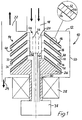
- a first embodiment of a centrifugal separator according to the invention is indicated in general by the reference numeral 10, which centrifugal separator is intended to separate off electrostatically-charged, solid and/or liquid particles in a flow of gas by means of the simultaneous, combined effect of electrostatic attraction forces and centrifugal forces.
- the separator 10 comprises a stationary casing 12, in which a rotor 14 is mounted in such a way that it can rotate, which rotor has a plurality of sedimentation surface elements mounted on it in the form of a stack of concentric, conical, plate-shaped elements, so-called insert plates 16, the construction of which will be described in greater detail below.
- the casing 12 has an inlet 18 for the gas that is to be cleaned.
- the inlet 18 opens out concentrically into a central inlet shaft 20 in the rotor 14.
- the casing 12 has, in addition, an outlet 22 for the gas that has been cleaned in the centrifugal separator 10, and an outlet 24 for the particles that have been separated off from the gas.
- the rotor 14 has a lower end 26 upon which the conical insert plates 16 are stacked, which insert plates are held a small axial distance apart by means of spacers (not shown). Only four plates 16 are shown in the drawing, for the sake of clarity, and these are shown with an exaggerated thickness and at an exaggerated distance apart.
- the rotor 14 is driven by a drive unit, here exemplified by an electrical motor 28, via a shaft 30.
- the conical insert plates 16 can be constructed of three layers, namely an outward-facing electrically-conductive surface layer 32, an inner, insulating intermediate layer 34 of a non-conductive material, and an inward-facing electrically-conductive surface layer 36. At least the inward-facing surface layers 36 are connected electrically to an electrical voltage source 38, via separate leads 40 that are shown schematically, or are alternatively connected to earth.
- the voltage source 38 can comprise an electrical generator, that generates a suitably high voltage for application to the inward-facing surface layers 36 of the plate elements by means of the rotation of the motor 28 and of the rotor 14, while the outward-facing surface layers 32 can be connected to earth via leads 42 or can have a potential of the same type as the particles, so that an electrical field is created between the opposing faces of the adjacent plate elements 16.
- an ionization unit 44 is arranged for charging the particles in the flow of gas, before they are led in between the conical insert plates 16.
- the ionization unit 44 can, for example, comprise various arrangements of corona wires 46 or the like, which can be arranged in the inlet 18 or in the inlet shaft 20, or can be integrated with an electronic unit (not shown) in the voltage source 38 or with a completely separate electronic unit (not shown).
- the corona wires 46 can, for example, be arranged along the axis and can be in the form of a ring in the shaft 20.
- the corona wires 46 can be arranged as rings that are concentric with the inlet gaps between the adjacent insert plates 16 (not shown), and can be arranged to rotate together with the rotor 14.
- the particles in the flow of gas can be given, for example, a negative potential, before they are led, together with the flow of gas, into the gaps 48 between the insert plates 16.
- the corona wires 46 can, for example, operate with a voltage of the order of -10 kV to -20 kV.
- the potential of the surface layers 36 can then, for example, be several kilovolts, for example approximately +5 kV.
- the centrifugal separator 10 in the embodiment according to Figure 1 works in principle in the following way:
- the embodiment of the invention according to Figure 1 can also be practicable for use in a counter-current gas cleaning method that is not shown in the drawing.
- the flow of gas flows in the opposite direction, that is from the outlet 22 (now inlet) in the casing 12 shown in the figure, into the gaps 48 between the insert plates 16, radially inwards towards the central shaft 20 of the rotor 14 and thereafter out through the inlet 18 shown in the drawing, that now forms the outlet for the clean gas.
- the ionization and charging of the gas particles in the flow of gas can be carried out either directly before they are led into the casing 12 via the inlet 22 or by means of corona wires (not shown) that are either stationary or rotate in the same direction, placed directly outside the outer periphery of the plate elements 16.
- the particles are trapped on the inward-facing, charged surfaces 36 by the combined effect of the centrifugal forces and electrostatic forces and form clusters or accumulations that flow out towards the periphery of the plates 16 due to the centrifugal forces and are thrown towards the inside of the wall 50 of the casing, after which the particles that have been separated off are caused to flow out through the outlet 24 for particles.
- the rotor 14a can alternatively be stationary and can be started up intermittently to throw the accumulation of particles out towards the inside of the surrounding casing (not shown) when large accumulations of particles have formed on the plate elements 16a, which accumulations of particles are then led out through an outlet for particles.
- the ionization of the particles in the gas upstream of the rotor 14a is carried out by one or more corona wires 46 arranged in the inlet 18.
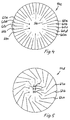
- Figure 3 shows schematically, in a plan view, that another embodiment is possible for a rotor 14b for the apparatus, where the insert plates are constructed as flat, radially-directed plate elements 52a, 52b arranged along the axis of the shaft of the rotor.
- Every other plate element 52a has an inner section 54, so that an ionization space 56 is formed between these, in which the particles in the flow of gas to be cleaned that is flowing into the rotor can be charged by means of a corona wire 58 that is rotating the same direction and that is located in the respective space 56.
- the plate elements 52a can be connected to earth, while the plate elements 52b lying between the plate elements 52a can have a potential of, for example, approximately +5 kV.
- the corona wires 58 can, for example, have a potential of between approximately -10 kV and -20 kV. This embodiment is suitable for the separation of very small and light particles, upon which the application of g-forces has little effect.
- the rotor can therefore be stationary during the actual depositing of the particles, during which the particles are caused, as a result of electrostatic attraction forces, to become attached to one of the opposing faces of the stationary plate elements 52a, 52b.
- the rotor 14b can then be started in order to throw the accumulations of particles out towards the inside of the surrounding casing (not shown), from where they are then led out through an outlet for particles.
- Figure 4 shows a rotor embodiment similar to the one in Figure 3 , but where plate elements 60a in the rotor 14c, that have radial inner end sections forming the ionization space 56c, have three plate elements 60b-d between them, the middle one of which 60c is connected to earth, as are the plate elements 60a, while the plate elements 60b and 60d can have a potential of, for example, approximately +5 kV.
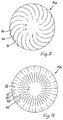
- the rotor 14d can alternatively have sedimentation plates constructed as plate elements 64a, 64b arranged in an axial direction along the shaft of the rotor, which plate elements are at an angle in relation to the radius in plan view. Every other plate element 64a can have an inner, radially-directed section 66, so that an ionization space 68 is formed between these, in which the particles in the flow of gas that is to be cleaned flowing into the rotor 14d can be charged by means of a corona wire 70 that rotates in the same direction and is located in the respective space 68.
- the plate elements 64a, 66 can be connected to earth, while the plate elements 64b located between these, that only have a tangential section, can have a potential of, for example, approximately +5 kV.
- the corona wires 70 can have, for example, a potential of approximately -10 to -20 kV.
- both heavy and light particles can be trapped on the plate element sections by means of a combined effect of the electrostatic attraction forces and centrifugal forces.
- Figure 6 shows schematically an embodiment of a rotor similar to the one in Figure 5 , but where the ionization spaces 72 are designed to be stationary in the central part of the rotor 14e, separated from the rotating, tangential plate elements 74.
- an ionization space is created that is less disruptive to the flow. Every other plate element 74 is connected to earth, while the elements lying between these are connected to positive potential.
- the corona wires 76 can, for example, be connected to a negative potential.
- Figure 7 shows schematically an embodiment of a rotor 14f, that differs from the one shown in Figure 6 in that the flow gaps 78 between the angled plate elements 80 have parallel opposing faces 82 and 84, with the face 84 having a positive potential, while the opposing face 82 is connected to earth.
- the plate elements 80 can be constructed of an insulating core 85 with electrically-conductive surface layers that form the faces 82 and 84.
- Figure 8 shows an embodiment of a rotor 14g that differs from the one shown in Figure 6 in that the plate elements 86 are curved instead. Also by this means, flow gaps 87 can be obtained between the plate elements 86 that have an electrical field with an essentially uniform field strength.
- FIG. 1-8 The embodiments shown in Figures 1-8 are intended for so-called concurrent separation, where the flow of gas with the particles flows from inside and outwards through plate-shaped sedimentation surface elements of the rotor, that is essentially in the same direction as the centrifugal force. It is, however, as pointed out above, possible within the framework of the present invention to modify all the embodiments to achieve a so-called counter-current separation, where the flow of gas flows in the opposite direction, that is from the outside and inwards towards the centre of the rotor and essentially counter to the direction of the centrifugal force.
- Figure 9 shows an example of this.
- corona wires 88 that are arranged in an axial direction are arranged radially outside the outer periphery of the sedimentation surface elements, here exemplified as flat, radially-oriented plate elements 90, which are alternately connected to earth and to a potential, for example a positive potential, and where, in a similar way as before, the corona wires 88 extend through ionization spaces 92 located upstream, which ionization spaces can be stationary in a surrounding casing (not shown).
- the ionization spaces 92 can, of course, also rotate in the same direction.
- the embodiment of the rotor 14h according to Figure 9 has completely radial, flat plate elements 90 suitable primarily for purely electrostatic separation of very small, light particles, where the accumulations of deposited particles on the plate elements 90 can be thrown off from these towards the surrounding casing as a result of the rotation of the rotor 14h.
- Corresponding counter-current separation concepts are also applicable for the other embodiments described above.
- the corona wires can be said to be connected to a negative voltage potential while the sedimentation surface elements are connected to a positive voltage potential, it should be noted that it is possible for the polarity to be reversed.
- the apparatus according to the embodiments in Figures 1 and 5-8 can also make it possible to carry out a classification of different fragments of a particular material that is to be found in a flow of gas.
- the rate of flow of the gas through the separator and/or regulating the charge potentials of the particles and of the inward-facing surfaces of the plate elements that are at an angle in relation to the centrifugal force and, if necessary, by regulating the speed of the rotor in a suitable way, depending upon the specific gravities of the particles that are to be separated off it is possible, for example, to control the separation in such a way that only fractions of a particular maximal density are separated off, while other particles of a lower density, according to requirements, are allowed to pass out from the casing 12 along with the gas.
- the casing 12 can also be arranged to rotate together with the rotor 14 in order to reduce the turbulence in the space between the inner wall of the casing and the rotor 14.
- flushing devices for flushing the plate elements with liquid at regular intervals.
- flushing devices of the type shown and described in SE 526 815 C2 ( WO2005087384 ).
- the gap between the plate elements and the wall elements, shown in Figures 6-9 , that delimits the ionization spaces, can also symbolize an electrical separation between these elements, for which reason, in these cases, the ionization spaces can be considered to be able to rotate together with the plate elements.
Applications Claiming Priority (2)
| Application Number | Priority Date | Filing Date | Title |
|---|---|---|---|
| SE0501495A SE528750C2 (sv) | 2005-06-27 | 2005-06-27 | Förfarande och anordning för separering av partiklar ur ett gasflöde |
| PCT/SE2006/050219 WO2007001232A1 (en) | 2005-06-27 | 2006-06-27 | Method and apparatus for separation of particles from a flow of gas |
Publications (4)
| Publication Number | Publication Date |
|---|---|
| EP1907124A1 EP1907124A1 (en) | 2008-04-09 |
| EP1907124A4 EP1907124A4 (en) | 2011-03-30 |
| EP1907124B1 EP1907124B1 (en) | 2013-06-05 |
| EP1907124B2 true EP1907124B2 (en) | 2016-10-26 |
Family
ID=37595391
Family Applications (1)
| Application Number | Title | Priority Date | Filing Date |
|---|---|---|---|
| EP06748058.2A Active EP1907124B2 (en) | 2005-06-27 | 2006-06-27 | Apparatus for separation of particles from a flow of gas |
Country Status (6)
| Country | Link |
|---|---|
| US (1) | US8029601B2 (sv) |
| EP (1) | EP1907124B2 (sv) |
| JP (2) | JP4923046B2 (sv) |
| CN (1) | CN101171087B (sv) |
| SE (1) | SE528750C2 (sv) |
| WO (1) | WO2007001232A1 (sv) |
Cited By (1)
| Publication number | Priority date | Publication date | Assignee | Title |
|---|---|---|---|---|
| WO2022039644A1 (en) | 2020-08-20 | 2022-02-24 | 3Nine Ab | Method and apparatus for centrifugal separation of particles from a gas flow |
Families Citing this family (70)
| Publication number | Priority date | Publication date | Assignee | Title |
|---|---|---|---|---|
| US8075668B2 (en) | 2005-03-29 | 2011-12-13 | Dresser-Rand Company | Drainage system for compressor separators |
| EP2063978B1 (en) | 2006-09-19 | 2014-07-09 | Dresser-Rand Company | Rotary separator drum seal |
| CA2663531C (en) | 2006-09-21 | 2014-05-20 | William C. Maier | Separator drum and compressor impeller assembly |
| EP2066948A4 (en) | 2006-09-25 | 2012-01-11 | Dresser Rand Co | ACCESS COVER FOR PRESSURED BOND DRAWER |
| EP2066453A4 (en) | 2006-09-25 | 2012-04-04 | Dresser Rand Co | FLUID DEFLECTOR FOR FLUID SEPARATION DEVICES |
| WO2008039733A2 (en) | 2006-09-25 | 2008-04-03 | Dresser-Rand Company | Compressor mounting system |
| US8061737B2 (en) | 2006-09-25 | 2011-11-22 | Dresser-Rand Company | Coupling guard system |
| CA2662780C (en) | 2006-09-25 | 2015-02-03 | William C. Maier | Axially moveable spool connector |
| EP2415507A1 (en) | 2006-09-26 | 2012-02-08 | Dresser-Rand Company | Improved static fluid separator device |
| EP2014346A1 (en) * | 2007-07-03 | 2009-01-14 | Evodos B.V. | Separating device |
| WO2009086598A1 (en) * | 2008-01-08 | 2009-07-16 | Glen Thomas A Hewson | Gas scrubber |
| WO2009111616A2 (en) | 2008-03-05 | 2009-09-11 | Dresser-Rand Company | Compressor assembly including separator and ejector pump |
| US8079805B2 (en) | 2008-06-25 | 2011-12-20 | Dresser-Rand Company | Rotary separator and shaft coupler for compressors |
| US7922218B2 (en) | 2008-06-25 | 2011-04-12 | Dresser-Rand Company | Shear ring casing coupler device |
| US8062400B2 (en) | 2008-06-25 | 2011-11-22 | Dresser-Rand Company | Dual body drum for rotary separators |
| US8317908B2 (en) * | 2008-11-18 | 2012-11-27 | Kaz Usa, Inc. | Triboelectric air purifier |
| SE533471C2 (sv) * | 2009-02-05 | 2010-10-05 | Alfa Laval Corp Ab | Anläggning för avskiljning av olja från en gasblandning samt förfarande för avskiljning av olja från en gasblandning |
| US8210804B2 (en) | 2009-03-20 | 2012-07-03 | Dresser-Rand Company | Slidable cover for casing access port |
| US8087901B2 (en) | 2009-03-20 | 2012-01-03 | Dresser-Rand Company | Fluid channeling device for back-to-back compressors |
| US8061972B2 (en) | 2009-03-24 | 2011-11-22 | Dresser-Rand Company | High pressure casing access cover |
| JP4794652B2 (ja) * | 2009-05-11 | 2011-10-19 | 定男 篠原 | 分離板型遠心分離機とその分離板 |
| SE533941C2 (sv) * | 2009-07-13 | 2011-03-08 | Alfa Laval Corp Ab | En centrifugalseparator |
| BR112012005866B1 (pt) | 2009-09-15 | 2021-01-19 | Dresser-Rand Company | aparelho para a separação de um fluido e método para a separação de um componente de peso específico mais alto de um componente de peso específico mais baixo de um fluido |
| CA2780306C (en) | 2009-11-16 | 2017-09-19 | Paradigm Waterworks, LLC | Systems for energy recovery and related methods |
| US8641793B2 (en) * | 2009-12-07 | 2014-02-04 | Paradigm Waterworks, LLC | Devices, systems, and methods for separation of feedstock components |
| US8794222B2 (en) * | 2010-01-27 | 2014-08-05 | Cummins Filtration Ip, Inc. | Crankcase ventilation inside-out flow rotating coalescer |
| EP2533905B1 (en) | 2010-02-10 | 2018-07-04 | Dresser-Rand Company | Separator fluid collector and method |
| KR101421856B1 (ko) * | 2010-02-25 | 2014-07-22 | 알파 라발 코포레이트 에이비 | 배기 가스 및 가스 세정기 유체 세척 장비 및 방법 |
| DE102010019605A1 (de) * | 2010-05-06 | 2011-11-10 | Rolls-Royce Deutschland Ltd & Co Kg | Fliehkraft-Ölabscheider für ein Flugzeugtriebwerk |
| DE102010019604A1 (de) * | 2010-05-06 | 2011-11-10 | Rolls-Royce Deutschland Ltd & Co Kg | Zentrifugal-Ölabscheider für ein Flugzeugtriebwerk |
| US8673159B2 (en) | 2010-07-15 | 2014-03-18 | Dresser-Rand Company | Enhanced in-line rotary separator |
| WO2012009159A2 (en) | 2010-07-15 | 2012-01-19 | Dresser-Rand Company | Radial vane pack for rotary separators |
| WO2012012018A2 (en) | 2010-07-20 | 2012-01-26 | Dresser-Rand Company | Combination of expansion and cooling to enhance separation |
| US8821362B2 (en) | 2010-07-21 | 2014-09-02 | Dresser-Rand Company | Multiple modular in-line rotary separator bundle |
| EP2614216B1 (en) | 2010-09-09 | 2017-11-15 | Dresser-Rand Company | Flush-enabled controlled flow drain |
| WO2013109235A2 (en) | 2010-12-30 | 2013-07-25 | Dresser-Rand Company | Method for on-line detection of resistance-to-ground faults in active magnetic bearing systems |
| US8994237B2 (en) | 2010-12-30 | 2015-03-31 | Dresser-Rand Company | Method for on-line detection of liquid and potential for the occurrence of resistance to ground faults in active magnetic bearing systems |
| US9206693B2 (en) * | 2011-02-18 | 2015-12-08 | General Electric Company | Apparatus, method, and system for separating particles from a fluid stream |
| CN102179317B (zh) * | 2011-02-28 | 2015-04-01 | 杜高升 | 离心油液净化机 |
| WO2012138545A2 (en) | 2011-04-08 | 2012-10-11 | Dresser-Rand Company | Circulating dielectric oil cooling system for canned bearings and canned electronics |
| EP2715167B1 (en) | 2011-05-27 | 2017-08-30 | Dresser-Rand Company | Segmented coast-down bearing for magnetic bearing systems |
| US8851756B2 (en) | 2011-06-29 | 2014-10-07 | Dresser-Rand Company | Whirl inhibiting coast-down bearing for magnetic bearing systems |
| EP4177224A1 (en) | 2011-07-29 | 2023-05-10 | Hayward Industries, Inc. | Chlorinator with replaceable cell cartridge |
| EP2736848A4 (en) | 2011-07-29 | 2016-03-16 | Hayward Ind Inc | SYSTEMS AND METHODS FOR CONTROLLING CHLOROMETERS |
| SE1150826A1 (sv) * | 2011-09-13 | 2012-12-11 | 3Nine Ab | Centrifugalsepareringsanordning |
| DE102012100438A1 (de) * | 2012-01-19 | 2013-07-25 | Elringklinger Ag | Abscheider für Flüssigkeitströpfchen aus einem Aerosol |
| DE102012104598A1 (de) * | 2012-05-29 | 2013-12-05 | Elringklinger Ag | Abscheider und Verfahren zum Abscheiden von Flüssigkeitströpfchen aus einem Aerosol |
| EP2735352A1 (en) | 2012-11-23 | 2014-05-28 | Alfa Laval Corporate AB | A centrifugal separator |
| EP2735351B1 (en) | 2012-11-23 | 2014-12-31 | Alfa Laval Corporate AB | Centrifugal separator for separating particles from a gas stream |
| EP2944391A1 (en) * | 2014-05-13 | 2015-11-18 | Alfa Laval Corporate AB | Centrifugal separator |
| KR101953492B1 (ko) * | 2014-09-30 | 2019-02-28 | 지디 미디어 에어콘디셔닝 이큅먼트 씨오 엘티디 | 집진 어셈블리, 공기 정화 장치 및 에어컨 |
| WO2016050218A2 (zh) * | 2014-09-30 | 2016-04-07 | 广东美的制冷设备有限公司 | 集尘组件、空气净化装置以及空调器 |
| SE538912C2 (sv) * | 2015-05-27 | 2017-02-07 | Apparatus for cleaning crank case gases | |
| EP3112034A1 (en) | 2015-07-03 | 2017-01-04 | Alfa Laval Corporate AB | Centrifugal separator structure and assembly |
| CN104998502B (zh) * | 2015-07-13 | 2017-05-24 | 北京矿冶研究总院 | 一种细颗粒物净化设备 |
| JP6542693B2 (ja) * | 2016-02-24 | 2019-07-10 | パナソニック株式会社 | 溶媒分離方法、溶媒分離装置及び溶媒分離システム |
| US20190316501A1 (en) * | 2016-05-23 | 2019-10-17 | Tokyo Roki Co., Ltd. | Stack of separation disks |
| CN106582183B (zh) * | 2017-02-08 | 2018-12-07 | 绍兴上虞亿天机电有限公司 | 一种机电设备除尘装置 |
| CA3057298A1 (en) | 2017-03-21 | 2018-09-27 | Hayward Industries, Inc. | Systems and methods for sanitizing pool and spa water |
| US10864526B2 (en) * | 2017-05-03 | 2020-12-15 | Airgard, Inc. | Electrode for electrostatic precipitator gas scrubbing apparatus |
| EP3415239B1 (en) * | 2017-06-15 | 2020-05-06 | Alfa Laval Corporate AB | Centrifugal separator and method of operating a centrifugal separator |
| DE102017125057A1 (de) * | 2017-10-26 | 2019-05-02 | Gea Mechanical Equipment Gmbh | Verfahren zur Verarbeitung eines fließfähigen Produktes und Zentrifuge |
| CN107716113B (zh) * | 2017-10-31 | 2023-10-20 | 珠海格力电器股份有限公司 | 一种集尘净化结构及除尘机 |
| CA3006692A1 (en) * | 2018-05-30 | 2019-11-30 | Kevin Allan Dooley Inc. | A system and method for extracting and separating botanical oils without the use of solvents |
| CN109737064B (zh) * | 2018-12-29 | 2023-12-15 | 广东汉德精密机械股份有限公司 | 一种具有电场油气分离功能的空压机 |
| CN109894277A (zh) * | 2019-03-08 | 2019-06-18 | 珠海格力电器股份有限公司 | 静电油网组件、风机及油烟机 |
| KR102219775B1 (ko) * | 2019-06-03 | 2021-02-25 | 한국기계연구원 | 세정 기능을 구비한 원심분리형 집진장치 |
| WO2021003065A1 (en) * | 2019-07-01 | 2021-01-07 | Cummins Filtration Ip, Inc. | Variable- angle baffle arrangement for air-liquid separation |
| US11433337B2 (en) | 2019-08-30 | 2022-09-06 | Paragon Space Development Corporation | Two-phase separator device for removing condensate or particulate from a gas stream |
| US20220297037A1 (en) * | 2021-03-19 | 2022-09-22 | Taiwan Semiconductor Manufacturing Company, Ltd. | Particle remover and method |
Family Cites Families (33)
| Publication number | Priority date | Publication date | Assignee | Title |
|---|---|---|---|---|
| US640694A (en) * | 1899-03-30 | 1900-01-02 | Marius Otto | Apparatus for producing electric discharges. |
| GB729612A (en) * | 1952-03-27 | 1955-05-11 | Air Preheater | Vortex-electrostatic gas cleaner |
| US2853151A (en) * | 1955-12-06 | 1958-09-23 | Research Corp | Electrified centrifugal dust separating device |
| BE624585A (sv) * | 1961-11-22 | |||
| FR87149E (fr) * | 1964-07-15 | 1966-06-17 | Procédé et dispositif applicables aux conduits de fumée et installations de ventilation pour purifier les gaz et assainir l'air pollué | |
| US3890103A (en) | 1971-08-25 | 1975-06-17 | Jinemon Konishi | Anti-pollution exhaust apparatus |
| JPS4841364A (sv) * | 1971-09-30 | 1973-06-16 | ||
| US3875061A (en) | 1973-08-27 | 1975-04-01 | James R Palma | Centrifugal separator with field effect separation |
| US4098578A (en) * | 1975-01-21 | 1978-07-04 | Stanton Anthony A | Ionization of exhaust gases |
| US4018578A (en) * | 1975-05-01 | 1977-04-19 | Ahlrich Willard K | Electrostatic precipitator |
| JPS5236371A (en) * | 1975-09-17 | 1977-03-19 | Matsushita Electric Ind Co Ltd | Two-stage system electric precipitator |
| SU668715A1 (ru) * | 1977-09-09 | 1979-06-25 | Karinskij Yulij | Центрифуга дл очистки нефтесодержащих вод |
| JPS61107957A (ja) * | 1984-11-01 | 1986-05-26 | Sanyo Electric Co Ltd | 空気清浄装置 |
| DE3500373A1 (de) * | 1985-01-08 | 1986-07-10 | Robert Bosch Gmbh, 7000 Stuttgart | Vorrichtung zum entfernen von festkoerperpartikeln, insbesondere von russteilchen aus dem abgas von brennkraftmaschinen |
| JPH0278454A (ja) | 1988-09-14 | 1990-03-19 | Mitsubishi Agricult Mach Co Ltd | 遠心静電浄油機 |
| US5224604A (en) * | 1990-04-11 | 1993-07-06 | Hydro Processing & Mining Ltd. | Apparatus and method for separation of wet and dry particles |
| JP2862353B2 (ja) | 1990-08-10 | 1999-03-03 | 三菱重工業株式会社 | 空気清浄装置 |
| CN1063626A (zh) * | 1991-02-02 | 1992-08-19 | 任世钧 | 旋转式静电气体净化设备 |
| US5380355A (en) * | 1993-05-06 | 1995-01-10 | Lebone Corporation | Airstream decontamination unit |
| JPH0731147U (ja) * | 1993-11-22 | 1995-06-13 | 東陶機器株式会社 | 多層円板空気浄化装置 |
| US5428220A (en) | 1993-11-29 | 1995-06-27 | The United States Of America As Represented By The Secretary Of Commerce | Aerosol mass spectrometer and method of classifying aerosol particles according to specific mass |
| SE517541C2 (sv) * | 1996-06-04 | 2002-06-18 | Eurus Airtech Ab | Anordning för rening av luft |
| DE29714203U1 (de) | 1997-08-08 | 1997-10-09 | Lta Lufttechnik Gmbh | Luftreinigungsgerät und eine Anlage zum Reinigen von Raumluft |
| JP2001120933A (ja) * | 1999-10-28 | 2001-05-08 | Kankyo Co Ltd | 空気清浄方法及び装置並びに加湿方法及び装置 |
| SE515302C2 (sv) * | 1999-11-15 | 2001-07-09 | Alfa Laval Ab | Ett sätt och en apparat för rening av gas |
| US6348086B1 (en) * | 2000-02-16 | 2002-02-19 | 3M Innovative Properties Company | Combination blower wheel and filter cartridge system for HVAC applications |
| JP2001276648A (ja) * | 2000-03-31 | 2001-10-09 | Ohm Denki Kk | 集塵装置および集塵方法 |
| DE10300976A1 (de) * | 2002-01-17 | 2003-07-31 | Mann & Hummel Filter | Zentrifuge zum Abscheiden von Partikeln aus einem Fluidstrom |
| JP2004141826A (ja) * | 2002-10-28 | 2004-05-20 | Zesu Giko:Kk | 電気集塵器 |
| JP2005046761A (ja) * | 2003-07-30 | 2005-02-24 | Ohm Denki Kk | 電気集塵機および浮遊粒子の集塵方法 |
| SE526815C2 (sv) * | 2004-03-16 | 2005-11-08 | 3Nine Ab | Anordning och förfarande för rengöring av en centrifugalseparator |
| SE527934C2 (sv) | 2004-06-03 | 2006-07-11 | Alfa Laval Corp Ab | En anordning och ett förfarande för rening av en gas |
| FR2879942B1 (fr) * | 2004-12-27 | 2007-01-26 | Commissariat Energie Atomique | Dispositif d'epuration d'un flux gazeux contenant des vapeurs condensables |
-
2005
- 2005-06-27 SE SE0501495A patent/SE528750C2/sv not_active IP Right Cessation
-
2006
- 2006-06-27 WO PCT/SE2006/050219 patent/WO2007001232A1/en active Application Filing
- 2006-06-27 CN CN2006800152120A patent/CN101171087B/zh active Active
- 2006-06-27 EP EP06748058.2A patent/EP1907124B2/en active Active
- 2006-06-27 JP JP2008518093A patent/JP4923046B2/ja active Active
- 2006-06-27 US US11/922,453 patent/US8029601B2/en active Active
-
2011
- 2011-07-01 JP JP2011147354A patent/JP5629652B2/ja active Active
Cited By (1)
| Publication number | Priority date | Publication date | Assignee | Title |
|---|---|---|---|---|
| WO2022039644A1 (en) | 2020-08-20 | 2022-02-24 | 3Nine Ab | Method and apparatus for centrifugal separation of particles from a gas flow |
Also Published As
| Publication number | Publication date |
|---|---|
| SE0501495L (sv) | 2006-12-28 |
| US20090266231A1 (en) | 2009-10-29 |
| JP5629652B2 (ja) | 2014-11-26 |
| CN101171087B (zh) | 2010-12-29 |
| EP1907124A4 (en) | 2011-03-30 |
| EP1907124B1 (en) | 2013-06-05 |
| WO2007001232A1 (en) | 2007-01-04 |
| EP1907124A1 (en) | 2008-04-09 |
| JP4923046B2 (ja) | 2012-04-25 |
| JP2008543558A (ja) | 2008-12-04 |
| US8029601B2 (en) | 2011-10-04 |
| CN101171087A (zh) | 2008-04-30 |
| SE528750C2 (sv) | 2007-02-06 |
| JP2011255372A (ja) | 2011-12-22 |
Similar Documents
| Publication | Publication Date | Title |
|---|---|---|
| EP1907124B2 (en) | Apparatus for separation of particles from a flow of gas | |
| US7704300B2 (en) | Device and a method for cleaning of a gas | |
| RU2469796C2 (ru) | Центробежный сепаратор | |
| US7594941B2 (en) | Rotary gas cyclone separator | |
| CA2496381C (en) | Grid type electrostatic separator/collector and method of using same | |
| CA2390944A1 (en) | A method and an apparatus for cleaning of gas | |
| JP2005530947A (ja) | クランクケースガスの浄化方法およびガス浄化分離機 | |
| EP2646135A2 (en) | Apparatus and method for removal of particulate matter from a gas | |
| CN104955580A (zh) | 离心分离器 | |
| AU2005257672B2 (en) | Tunnel fan electrostatic filter | |
| JPH02303555A (ja) | 強磁気セパレータ | |
| US4029485A (en) | Gas cleaners | |
| US5149339A (en) | Rotary device for removing particulates from a gas stream | |
| WO2012139642A1 (en) | Apparatus for removal of particulate matter from a gas | |
| KR102219775B1 (ko) | 세정 기능을 구비한 원심분리형 집진장치 | |
| SE533941C2 (sv) | En centrifugalseparator | |
| WO2008091519A1 (en) | Device for remediation of gaseous and aerosol streams | |
| JP2001276648A (ja) | 集塵装置および集塵方法 | |
| WO1996035521A1 (fr) | Separateur | |
| US11660612B2 (en) | Method for processing a flowable product by electrically charging particles in the flowable product and a disc stack of a centrifuge | |
| SU265074A1 (ru) | Электрофильтр для очистки газов | |
| SU975038A1 (ru) | Устройство дл центробежной очистки газа | |
| KR20100093625A (ko) | 미립자 합체형 고형물분리기 | |
| JPH0564756A (ja) | 遠心力場を用いた連続粒子分離装置 |
Legal Events
| Date | Code | Title | Description |
|---|---|---|---|
| PUAI | Public reference made under article 153(3) epc to a published international application that has entered the european phase |
Free format text: ORIGINAL CODE: 0009012 |
|
| 17P | Request for examination filed |
Effective date: 20070926 |
|
| AK | Designated contracting states |
Kind code of ref document: A1 Designated state(s): AT BE BG CH CY CZ DE DK EE ES FI FR GB GR HU IE IS IT LI LT LU LV MC NL PL PT RO SE SI SK TR |
|
| DAX | Request for extension of the european patent (deleted) | ||
| A4 | Supplementary search report drawn up and despatched |
Effective date: 20110224 |
|
| GRAP | Despatch of communication of intention to grant a patent |
Free format text: ORIGINAL CODE: EPIDOSNIGR1 |
|
| GRAC | Information related to communication of intention to grant a patent modified |
Free format text: ORIGINAL CODE: EPIDOSCIGR1 |
|
| GRAJ | Information related to disapproval of communication of intention to grant by the applicant or resumption of examination proceedings by the epo deleted |
Free format text: ORIGINAL CODE: EPIDOSDIGR1 |
|
| GRAS | Grant fee paid |
Free format text: ORIGINAL CODE: EPIDOSNIGR3 |
|
| GRAP | Despatch of communication of intention to grant a patent |
Free format text: ORIGINAL CODE: EPIDOSNIGR1 |
|
| GRAP | Despatch of communication of intention to grant a patent |
Free format text: ORIGINAL CODE: EPIDOSNIGR1 |
|
| INTG | Intention to grant announced |
Effective date: 20130405 |
|
| GRAA | (expected) grant |
Free format text: ORIGINAL CODE: 0009210 |
|
| AK | Designated contracting states |
Kind code of ref document: B1 Designated state(s): AT BE BG CH CY CZ DE DK EE ES FI FR GB GR HU IE IS IT LI LT LU LV MC NL PL PT RO SE SI SK TR |
|
| REG | Reference to a national code |
Ref country code: GB Ref legal event code: FG4D |
|
| REG | Reference to a national code |
Ref country code: CH Ref legal event code: EP |
|
| REG | Reference to a national code |
Ref country code: AT Ref legal event code: REF Ref document number: 615321 Country of ref document: AT Kind code of ref document: T Effective date: 20130615 |
|
| REG | Reference to a national code |
Ref country code: IE Ref legal event code: FG4D |
|
| REG | Reference to a national code |
Ref country code: DE Ref legal event code: R096 Ref document number: 602006036674 Country of ref document: DE Effective date: 20130801 |
|
| REG | Reference to a national code |
Ref country code: AT Ref legal event code: MK05 Ref document number: 615321 Country of ref document: AT Kind code of ref document: T Effective date: 20130605 |
|
| PG25 | Lapsed in a contracting state [announced via postgrant information from national office to epo] |
Ref country code: SE Free format text: LAPSE BECAUSE OF FAILURE TO SUBMIT A TRANSLATION OF THE DESCRIPTION OR TO PAY THE FEE WITHIN THE PRESCRIBED TIME-LIMIT Effective date: 20130605 Ref country code: AT Free format text: LAPSE BECAUSE OF FAILURE TO SUBMIT A TRANSLATION OF THE DESCRIPTION OR TO PAY THE FEE WITHIN THE PRESCRIBED TIME-LIMIT Effective date: 20130605 Ref country code: ES Free format text: LAPSE BECAUSE OF FAILURE TO SUBMIT A TRANSLATION OF THE DESCRIPTION OR TO PAY THE FEE WITHIN THE PRESCRIBED TIME-LIMIT Effective date: 20130916 Ref country code: FI Free format text: LAPSE BECAUSE OF FAILURE TO SUBMIT A TRANSLATION OF THE DESCRIPTION OR TO PAY THE FEE WITHIN THE PRESCRIBED TIME-LIMIT Effective date: 20130605 Ref country code: GR Free format text: LAPSE BECAUSE OF FAILURE TO SUBMIT A TRANSLATION OF THE DESCRIPTION OR TO PAY THE FEE WITHIN THE PRESCRIBED TIME-LIMIT Effective date: 20130906 Ref country code: LT Free format text: LAPSE BECAUSE OF FAILURE TO SUBMIT A TRANSLATION OF THE DESCRIPTION OR TO PAY THE FEE WITHIN THE PRESCRIBED TIME-LIMIT Effective date: 20130605 Ref country code: SI Free format text: LAPSE BECAUSE OF FAILURE TO SUBMIT A TRANSLATION OF THE DESCRIPTION OR TO PAY THE FEE WITHIN THE PRESCRIBED TIME-LIMIT Effective date: 20130605 |
|
| REG | Reference to a national code |
Ref country code: NL Ref legal event code: VDEP Effective date: 20130605 |
|
| REG | Reference to a national code |
Ref country code: LT Ref legal event code: MG4D |
|
| PG25 | Lapsed in a contracting state [announced via postgrant information from national office to epo] |
Ref country code: BG Free format text: LAPSE BECAUSE OF FAILURE TO SUBMIT A TRANSLATION OF THE DESCRIPTION OR TO PAY THE FEE WITHIN THE PRESCRIBED TIME-LIMIT Effective date: 20130905 Ref country code: PL Free format text: LAPSE BECAUSE OF FAILURE TO SUBMIT A TRANSLATION OF THE DESCRIPTION OR TO PAY THE FEE WITHIN THE PRESCRIBED TIME-LIMIT Effective date: 20130605 |
|
| PG25 | Lapsed in a contracting state [announced via postgrant information from national office to epo] |
Ref country code: LV Free format text: LAPSE BECAUSE OF FAILURE TO SUBMIT A TRANSLATION OF THE DESCRIPTION OR TO PAY THE FEE WITHIN THE PRESCRIBED TIME-LIMIT Effective date: 20130605 |
|
| PG25 | Lapsed in a contracting state [announced via postgrant information from national office to epo] |
Ref country code: BE Free format text: LAPSE BECAUSE OF FAILURE TO SUBMIT A TRANSLATION OF THE DESCRIPTION OR TO PAY THE FEE WITHIN THE PRESCRIBED TIME-LIMIT Effective date: 20130605 Ref country code: CZ Free format text: LAPSE BECAUSE OF FAILURE TO SUBMIT A TRANSLATION OF THE DESCRIPTION OR TO PAY THE FEE WITHIN THE PRESCRIBED TIME-LIMIT Effective date: 20130605 Ref country code: EE Free format text: LAPSE BECAUSE OF FAILURE TO SUBMIT A TRANSLATION OF THE DESCRIPTION OR TO PAY THE FEE WITHIN THE PRESCRIBED TIME-LIMIT Effective date: 20130605 Ref country code: SK Free format text: LAPSE BECAUSE OF FAILURE TO SUBMIT A TRANSLATION OF THE DESCRIPTION OR TO PAY THE FEE WITHIN THE PRESCRIBED TIME-LIMIT Effective date: 20130605 Ref country code: PT Free format text: LAPSE BECAUSE OF FAILURE TO SUBMIT A TRANSLATION OF THE DESCRIPTION OR TO PAY THE FEE WITHIN THE PRESCRIBED TIME-LIMIT Effective date: 20131007 Ref country code: IS Free format text: LAPSE BECAUSE OF FAILURE TO SUBMIT A TRANSLATION OF THE DESCRIPTION OR TO PAY THE FEE WITHIN THE PRESCRIBED TIME-LIMIT Effective date: 20131005 |
|
| REG | Reference to a national code |
Ref country code: CH Ref legal event code: PL |
|
| PG25 | Lapsed in a contracting state [announced via postgrant information from national office to epo] |
Ref country code: NL Free format text: LAPSE BECAUSE OF FAILURE TO SUBMIT A TRANSLATION OF THE DESCRIPTION OR TO PAY THE FEE WITHIN THE PRESCRIBED TIME-LIMIT Effective date: 20130605 Ref country code: RO Free format text: LAPSE BECAUSE OF FAILURE TO SUBMIT A TRANSLATION OF THE DESCRIPTION OR TO PAY THE FEE WITHIN THE PRESCRIBED TIME-LIMIT Effective date: 20130605 |
|
| PLBI | Opposition filed |
Free format text: ORIGINAL CODE: 0009260 |
|
| REG | Reference to a national code |
Ref country code: IE Ref legal event code: MM4A |
|
| PG25 | Lapsed in a contracting state [announced via postgrant information from national office to epo] |
Ref country code: MC Free format text: LAPSE BECAUSE OF FAILURE TO SUBMIT A TRANSLATION OF THE DESCRIPTION OR TO PAY THE FEE WITHIN THE PRESCRIBED TIME-LIMIT Effective date: 20130605 |
|
| 26 | Opposition filed |
Opponent name: ALFA LAVAL CORPORATE AB Effective date: 20140303 |
|
| PLAX | Notice of opposition and request to file observation + time limit sent |
Free format text: ORIGINAL CODE: EPIDOSNOBS2 |
|
| PG25 | Lapsed in a contracting state [announced via postgrant information from national office to epo] |
Ref country code: CH Free format text: LAPSE BECAUSE OF NON-PAYMENT OF DUE FEES Effective date: 20130630 Ref country code: DK Free format text: LAPSE BECAUSE OF FAILURE TO SUBMIT A TRANSLATION OF THE DESCRIPTION OR TO PAY THE FEE WITHIN THE PRESCRIBED TIME-LIMIT Effective date: 20130605 Ref country code: LI Free format text: LAPSE BECAUSE OF NON-PAYMENT OF DUE FEES Effective date: 20130630 Ref country code: IE Free format text: LAPSE BECAUSE OF NON-PAYMENT OF DUE FEES Effective date: 20130627 |
|
| REG | Reference to a national code |
Ref country code: DE Ref legal event code: R026 Ref document number: 602006036674 Country of ref document: DE Effective date: 20140303 |
|
| PG25 | Lapsed in a contracting state [announced via postgrant information from national office to epo] |
Ref country code: IT Free format text: LAPSE BECAUSE OF FAILURE TO SUBMIT A TRANSLATION OF THE DESCRIPTION OR TO PAY THE FEE WITHIN THE PRESCRIBED TIME-LIMIT Effective date: 20130605 |
|
| PLBB | Reply of patent proprietor to notice(s) of opposition received |
Free format text: ORIGINAL CODE: EPIDOSNOBS3 |
|
| PG25 | Lapsed in a contracting state [announced via postgrant information from national office to epo] |
Ref country code: CY Free format text: LAPSE BECAUSE OF FAILURE TO SUBMIT A TRANSLATION OF THE DESCRIPTION OR TO PAY THE FEE WITHIN THE PRESCRIBED TIME-LIMIT Effective date: 20130605 Ref country code: TR Free format text: LAPSE BECAUSE OF FAILURE TO SUBMIT A TRANSLATION OF THE DESCRIPTION OR TO PAY THE FEE WITHIN THE PRESCRIBED TIME-LIMIT Effective date: 20130605 |
|
| PG25 | Lapsed in a contracting state [announced via postgrant information from national office to epo] |
Ref country code: HU Free format text: LAPSE BECAUSE OF FAILURE TO SUBMIT A TRANSLATION OF THE DESCRIPTION OR TO PAY THE FEE WITHIN THE PRESCRIBED TIME-LIMIT; INVALID AB INITIO Effective date: 20060627 Ref country code: LU Free format text: LAPSE BECAUSE OF NON-PAYMENT OF DUE FEES Effective date: 20130627 |
|
| REG | Reference to a national code |
Ref country code: FR Ref legal event code: PLFP Year of fee payment: 11 |
|
| PUAH | Patent maintained in amended form |
Free format text: ORIGINAL CODE: 0009272 |
|
| STAA | Information on the status of an ep patent application or granted ep patent |
Free format text: STATUS: PATENT MAINTAINED AS AMENDED |
|
| 27A | Patent maintained in amended form |
Effective date: 20161026 |
|
| AK | Designated contracting states |
Kind code of ref document: B2 Designated state(s): AT BE BG CH CY CZ DE DK EE ES FI FR GB GR HU IE IS IT LI LT LU LV MC NL PL PT RO SE SI SK TR |
|
| REG | Reference to a national code |
Ref country code: DE Ref legal event code: R102 Ref document number: 602006036674 Country of ref document: DE |
|
| RIN2 | Information on inventor provided after grant (corrected) |
Inventor name: FRANZEN, PETER Inventor name: INGE, CLAES Inventor name: LAGERSTEDT, TORGNY |
|
| PG25 | Lapsed in a contracting state [announced via postgrant information from national office to epo] |
Ref country code: LV Free format text: LAPSE BECAUSE OF FAILURE TO SUBMIT A TRANSLATION OF THE DESCRIPTION OR TO PAY THE FEE WITHIN THE PRESCRIBED TIME-LIMIT Effective date: 20161026 |
|
| REG | Reference to a national code |
Ref country code: FR Ref legal event code: PLFP Year of fee payment: 12 |
|
| PG25 | Lapsed in a contracting state [announced via postgrant information from national office to epo] |
Ref country code: LV Free format text: LAPSE BECAUSE OF FAILURE TO SUBMIT A TRANSLATION OF THE DESCRIPTION OR TO PAY THE FEE WITHIN THE PRESCRIBED TIME-LIMIT Effective date: 20130605 |
|
| REG | Reference to a national code |
Ref country code: FR Ref legal event code: PLFP Year of fee payment: 13 |
|
| REG | Reference to a national code |
Ref country code: DE Ref legal event code: R081 Ref document number: 602006036674 Country of ref document: DE Owner name: GRIMALDI DEVELOPMENT AB, SE Free format text: FORMER OWNER: 3NINE AB, NACKA STRAND, SE |
|
| PGFP | Annual fee paid to national office [announced via postgrant information from national office to epo] |
Ref country code: FR Payment date: 20230529 Year of fee payment: 18 Ref country code: DE Payment date: 20230530 Year of fee payment: 18 |
|
| PGFP | Annual fee paid to national office [announced via postgrant information from national office to epo] |
Ref country code: GB Payment date: 20230601 Year of fee payment: 18 |