EP1892872A2 - Fehlerprüfung für Datenübertragung zwischen einer Leitstation und einer Folgestation - Google Patents
Fehlerprüfung für Datenübertragung zwischen einer Leitstation und einer Folgestation Download PDFInfo
- Publication number
- EP1892872A2 EP1892872A2 EP07016467A EP07016467A EP1892872A2 EP 1892872 A2 EP1892872 A2 EP 1892872A2 EP 07016467 A EP07016467 A EP 07016467A EP 07016467 A EP07016467 A EP 07016467A EP 1892872 A2 EP1892872 A2 EP 1892872A2
- Authority
- EP
- European Patent Office
- Prior art keywords
- data
- error check
- error
- data transfer
- master unit
- Prior art date
- Legal status (The legal status is an assumption and is not a legal conclusion. Google has not performed a legal analysis and makes no representation as to the accuracy of the status listed.)
- Granted
Links
- 238000012546 transfer Methods 0.000 title claims abstract description 62
- 238000011144 upstream manufacturing Methods 0.000 claims abstract description 30
- 238000012937 correction Methods 0.000 claims abstract description 29
- 238000000034 method Methods 0.000 claims abstract description 20
- 230000005540 biological transmission Effects 0.000 description 9
- 238000010276 construction Methods 0.000 description 9
- 238000012423 maintenance Methods 0.000 description 6
- 238000004891 communication Methods 0.000 description 5
- 239000000470 constituent Substances 0.000 description 3
- 238000012545 processing Methods 0.000 description 3
- 238000006243 chemical reaction Methods 0.000 description 1
- 238000012986 modification Methods 0.000 description 1
- 230000004048 modification Effects 0.000 description 1
- 230000003287 optical effect Effects 0.000 description 1
Images



Classifications
-
- H—ELECTRICITY
- H04—ELECTRIC COMMUNICATION TECHNIQUE
- H04L—TRANSMISSION OF DIGITAL INFORMATION, e.g. TELEGRAPHIC COMMUNICATION
- H04L1/00—Arrangements for detecting or preventing errors in the information received
- H04L1/004—Arrangements for detecting or preventing errors in the information received by using forward error control
- H04L1/0045—Arrangements at the receiver end
-
- H—ELECTRICITY
- H04—ELECTRIC COMMUNICATION TECHNIQUE
- H04L—TRANSMISSION OF DIGITAL INFORMATION, e.g. TELEGRAPHIC COMMUNICATION
- H04L1/00—Arrangements for detecting or preventing errors in the information received
- H04L1/24—Testing correct operation
- H04L1/245—Testing correct operation by using the properties of transmission codes
-
- H—ELECTRICITY
- H04—ELECTRIC COMMUNICATION TECHNIQUE
- H04L—TRANSMISSION OF DIGITAL INFORMATION, e.g. TELEGRAPHIC COMMUNICATION
- H04L1/00—Arrangements for detecting or preventing errors in the information received
- H04L2001/0092—Error control systems characterised by the topology of the transmission link
- H04L2001/0094—Bus
-
- H—ELECTRICITY
- H04—ELECTRIC COMMUNICATION TECHNIQUE
- H04L—TRANSMISSION OF DIGITAL INFORMATION, e.g. TELEGRAPHIC COMMUNICATION
- H04L1/00—Arrangements for detecting or preventing errors in the information received
- H04L2001/0092—Error control systems characterised by the topology of the transmission link
- H04L2001/0097—Relays
Definitions
- the present invention relates to a data transfer method and a data transfer apparatus for making a robot perform desired operations in various driving axes in synchronism with each other.
- a data transfer method for operating various axes of a machine tool or a robot in synchronism with each other there is a known data transfer method in which a master unit, such as a controller situated on an upstream side and slave units, such as a plurality of servo amplifiers situated on a downstream side are connected in series by a daisy chain system with a serial bus, and data having an appended error check code or data having an appended error correction code are transferred from the upstream side to the downstream side.
- a master unit such as a controller situated on an upstream side
- slave units such as a plurality of servo amplifiers situated on a downstream side
- data having an appended error check code or data having an appended error correction code are transferred from the upstream side to the downstream side.
- Patent Reference 1 discloses an example of such a data transfer method.
- a plurality of servo amplifiers are connected in series via communication lines such as optical cables to a numerical control apparatus by a daisy chain system.
- the numerical control apparatus transmits a position command or the like via the communication lines to various servo amplifiers, and various servo amplifiers receive the position command or the like.
- Each servo amplifier drives a servo motor in accordance with the received position command or the like.
- the control apparatus situated on the upstream side is adapted to receive feedback signals from slave units which include the servo amplifiers and servo motors.
- Patent Reference 2 discloses another example of a data transfer method.
- data can be transferred at high speed between a plurality of slave units, which are connected to a master unit.
- the data transfer apparatus is provided with a communication rank control portion and uses control lines provided separately in addition to a data communication line to determine whether or not the communication data should be transmitted.
- a data transfer method for connecting a master unit on an upstream side and a plurality of slave units on a downstream side in series with a serial bus by a daisy chain system, and transferring data having an appended error check code or error correction code between a data transmitter and a data receiver
- the data transfer method comprising: transferring the data flowing in the serial bus in the slave unit from the data transmitter to the data receiver without performing an error check or error correction of the data; performing the error check of the data in a circuit provided in the slave unit aside from a circuit flowing the data; and informing a result of the error check to the master unit individually by the slave unit which has performed the error check of the data.
- data with error check code or error correction code are transferred from the data transmitter to the data receiver without performing error check at the slave unit, it is possible to transfer data at high speed between a plurality of slave units connected to a daisy chain. Since error check of data with error check code or error correction code is performed in a separate circuit aside from the circuit through which the data with error check code or error correction code flow in the slave unit, the slave unit in which the error has occurred can be identified without lowering the data transfer speed of data transferred from the data transmitter to the data receiver. Since the result of the error check is individually sent to the master unit, the slave unit in which the error has occurred can be recognized via the master unit. Therefore, data can be transferred at high speed, the slave unit in which the error has occurred can be identified so that maintenance for the machine tool or the robot can be improved.
- a data transfer apparatus in which a master unit on an upstream side and a plurality of slave units on a downstream side are connected in series with a serial bus by a daisy chain system, and data having an appended error check code or error correction code are transferred between a data transmitter and a data receiver, the apparatus comprising: a data transfer portion for transferring the data flowing in the serial in slave unit bus from the data transmitter to said data receiver without performing an error check or error correction of the data; an error check portion for performing the error check of the data in a circuit provided in the slave unit aside from a circuit flowing the data; and an error informing portion for informing a result of the error check individually to the master unit in the slave unit which has the error check portion.
- the data with error check code or error correction code can be transferred by the data transfer portion without performing error check or error correction, high speed data transfer is possible between a plurality of slave units connected by the daisy chain system.
- error check of the data with error check code or error correction code can be performed by the error check portion in a circuit provided in the slave unit aside from the circuit through which the data with error check code or error correction code flow, and the slave unit in which the error has occurred can be thereby identified.
- the slave unit in which the error has occurred can be recognized via the master unit. Therefore, data transfer can be carried out at high speed, the slave unit in which the error has occurred can be identified and maintenance on the machine tool or the robot can be improved.
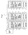
- a data transfer apparatus 1 comprises a master unit 2 as a control apparatus situated on an upstream side and a plurality of slave units 3 situated on a downstream side.
- Each of the slave units 3 comprises a servo amplifier 4 and a servo motor 5.
- the master unit 2 and a plurality of slave units 3 are connected in series by a daisy chain system with serial bus, such that data can be transferred in both directions between the master unit 2 and the slave unit 3 on the downstream side.
- servo motors 5 are controlled and driven by the control data transferred from the master unit 2 to the slave units 3 (from upstream side to downstream side), and the state of the servo motors 5 is fed back by the feedback data transferred from the slave units 3 to the master unit 2 (from downstream side to upstream side).
- Data having an error check code or error correction code are used as the transferred data, and are transferred in the form of packets. Therefore, reliability of data transferred is increased by using data having the error check code or error correction code.
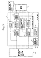
- the master unit 2 is composed of a processor 7, a ROM 8, a RAM 9, a transmission control circuit 10, a reception control circuit 12, a DSP (Digital Signal Processor) 18, a screen display circuit 14 and the like.
- ROM 8, RAM 9, the transmission control circuit 10, the reception control circuit 11, DSP 18, the screen display circuit 14 are connected to the processor 7 via a system bus 13, and is the same circuit construction as in prior art, and is adapted to control the servo motors 5 based on the feedback data (feedback signal) in position loop control or in velocity loop control, as well as in circuit loop control based on the current feedback signal from the servo amplifiers 4.
- An P/S converter (not shown) for converting a parallel signal to a serial signal is connected to the transmission control circuit 10, and sends out control data that is converted to a serial signal into a serial bus 6 as a signal line.
- feedback data that is input from the slave units 3 via the serial bus 6 is input into an S/P converter (not shown) for converting a serial signal to a parallel signal, and is received by the reception control circuit 11.
- a transmit data generating circuit 12 for generating control data by error check coding or error correction encoding process is provided between the transmission control circuit 10 and the P/S converter. Data generated in the transmit data generating circuit 12 is transmitted via the serial bus 6 to the slave units 3 on the downstream side. Data transfer from the upstream side to downstream side corresponds to a data transfer method according to a fourth embodiment of the present invention.
- the reception control circuit 11 comprises an error check portion 15 for checking whether or not there is an error in the received data with error check code.
- the error check portion 15 the presence or absence of an error in the data transferred from the downstream side can be checked.
- the slave unit where the error has occurred can be specified by displaying the presence or absence of an error on the screen of a display 17 using an error displaying portion 16.
- the error displaying portion 16 is composed of the master unit as shown in Fig. 2, and functions by the operation of the processor 7, ROM 8, RAM 9, the screen display circuit 14 and the like.
- the processor 7 examines the error check portion 15, operates the screen display circuit 14, and displays the presence or absence of an error on the screen of the display 17.
- the slave unit 3 comprises a first circuit portion for processing (relay processing) data transferred from the upstream side to the downstream side, and a second circuit portion for processing data transferred from the downstream side to the upstream side.
- the control data transferred from the master unit 2 or the slave unit 3 on the upstream side branch point and flows via a buffer circuit 20 and an S/P converter (not shown) to the reception control circuit 21.
- the reception control circuit 21 is connected via a decoding portion 22 to a current control circuit 23.
- data is inspected by using error correction code, and when an error is detected, data received is dumped, and the value previously received correctly is used as it is, or data is corrected so as not to use the data having the detected error.
- a current command (torque command) is sent out to the servo motor 4 based on the inspected and corrected data.
- the buffer circuit 20 is connected to the serial bus 6 and passes the data received from the upstream side to the next slave unit 3 without performing an error check or error correction.
- the second circuit portion comprises a data transfer portion 25, error check portion 35, and error informing portion 36.
- the data transfer portion 25 relays data with error check code transferred from the downstream side by adding a feedback signal from the servo motor 5 and signal data prepared from the information within the slave unit and without performing an error check on data transferred from the downstream side to the upstream side.
- the control data transferred from the slave unit 3 on downstream side branch at the branch point to flow to the buffer circuit 26.
- the buffer circuit 26 includes a S/P converter (not shown) and is connected to the transmission control circuit 28, such that the data after signal conversion flows to the transmission control circuit 28.
- the total data of the slave unit 3 and the slave units 3 on the downstream side are transferred via the transmission control circuit 28 to the upstream side. Therefore, data with error check code or error correction code is transferred by the data transfer portion without performing an error check so that high speed data transfer is possible between a plurality of slave units 3 connected by a daisy chain system.
- the error check portion 35 is a separate circuit provided in addition to aside from the data transfer portion 25 for checking the presence or absence of an error, and is connected to the transmission control circuit 28. Data with error check code flow from the transmission control circuit 28 without being subjected to error check into the error check portion 35, where the error check code is read in and error check is performed.
- the result of the error check is transmitted via the error informing portion 36 on a signal line 37 provided aside from the serial bus 6 to the master unit 2, where it is stored in a buffer domain (not shown) for the result of the error check to be displayed. If, for example, there is ample time for the serial bus to transmit the result of error check after high speed data transfer has been completed and before the next data is transferred, it is also possible to use the serial bus to transmit the result of error check of data to the master unit 2.
- this error check portion is provided in the reception control circuit for data that flow from the upstream side to the downstream side, and as in the fourth embodiment, this error check portion is used to transmit and inform the result of error check of data that flow from the upstream side to the downstream side, to the master unit 2.
- the error informing portion 36 are means with which the slave unit provided with the error check portion 35 informs the result of error check individually to the master unit 2.
- the master unit upon reception of the notification, displays the slave unit in which an error has occurred on the display 17 (see Fig. 4) using the error displaying portion 16.
- the data transfer apparatus 1A differs from that in the first embodiment in that an error counter 40 is provided in the master unit 2.
- the error counter 40 counts and stores the number of errors in individual slave units 3 connected to the master unit 2 by a daisy chain system.
- By providing such an error counter 40 it is possible to identify the slave unit 3 in which error has occurred when maintenance is to be performed on the machine tool or the robot having the master unit 2 and a plurality of slave units 3.
- Other constituents that are in common with the first embodiment are denoted by the same reference numerals and symbols, and duplicate explanation thereof will be omitted.
- the data transfer apparatus 1B according to this embodiment is the same as that in the second embodiment in that error counters 41 are provided, but differs from that in the second embodiment in that error counters are provided in the slave units 3 (except for the slave unit 3 on the utmost downstream side). By providing error counters 41 in the slave units 3. It is possible to identify the slave unit 3 in which an error has occurred.
- the data transfer apparatus 1C differs from that in the first embodiment in that data with error check code or error code flow from the upstream side to the downstream side and an alarm displaying portion 43 in place of an error displaying portion 16 is provided in the master unit 2A.
- Data is prepared by a transmit data generating circuit 12 (see Fig. 2) in the master unit 2A and transferred to the slave units 3A on the downstream side.
- the data transfer portion 25 in the slave units 3A, data branch into two at a branch point and flow into the buffer circuit and the reception control circuit, respectively.
- One of the data that flows via the buffer circuit is transferred as it is to the slave units 3A without being subjected to error check or the like.
- the other data that flows via the reception control circuit is subjected to error check by an error check portion 35 (not shown), and the control data flow to the servo motor.
- the result of the error check by the error check portion 35 is sent via informing portion (not shown) to the master unit 2A.
- An alarm displaying portion 43 provided in place of the error displaying portion 16 in the first embodiment, displays an alarm when data error has occurred in a predetermined slave unit 3A.
- Other constituents are in common with the first embodiment, and therefore duplicate explanation will be omitted here.
- the error check portion 35 is provided separately from the data transfer portion 25 in the slave units 3, 3A, so that the slave units 3, 3A in which an error has occurred can be identified without lowering the data transfer speed of data transferred from downstream side to upstream side, or from the upstream side to the downstream side, and maintenance on the machine tool or the robot can therefore be improved.
Landscapes
- Engineering & Computer Science (AREA)
- Computer Networks & Wireless Communication (AREA)
- Signal Processing (AREA)
- Numerical Control (AREA)
- Small-Scale Networks (AREA)
- Communication Control (AREA)
- Information Transfer Systems (AREA)
- Manipulator (AREA)
Applications Claiming Priority (1)
| Application Number | Priority Date | Filing Date | Title |
|---|---|---|---|
| JP2006228053A JP4226620B2 (ja) | 2006-08-24 | 2006-08-24 | データ転送方式及びデータ転送装置 |
Publications (3)
| Publication Number | Publication Date |
|---|---|
| EP1892872A2 true EP1892872A2 (de) | 2008-02-27 |
| EP1892872A3 EP1892872A3 (de) | 2012-06-13 |
| EP1892872B1 EP1892872B1 (de) | 2018-02-28 |
Family
ID=38808972
Family Applications (1)
| Application Number | Title | Priority Date | Filing Date |
|---|---|---|---|
| EP07016467.8A Ceased EP1892872B1 (de) | 2006-08-24 | 2007-08-22 | Fehlerprüfung für Datenübertragung zwischen einer Leitstation und einer Folgestation |
Country Status (4)
| Country | Link |
|---|---|
| US (1) | US7653768B2 (de) |
| EP (1) | EP1892872B1 (de) |
| JP (1) | JP4226620B2 (de) |
| CN (1) | CN101132254B (de) |
Cited By (1)
| Publication number | Priority date | Publication date | Assignee | Title |
|---|---|---|---|---|
| WO2021004835A1 (de) * | 2019-07-11 | 2021-01-14 | Inventio Ag | Verfahren und datennetzwerk zum kommunizieren von dateninhalten, insbesondere in einer aufzuganlage |
Families Citing this family (24)
| Publication number | Priority date | Publication date | Assignee | Title |
|---|---|---|---|---|
| JP2008092523A (ja) * | 2006-10-05 | 2008-04-17 | Nec Corp | データ転送装置及びデータ処理方法 |
| US9598897B2 (en) * | 2007-06-21 | 2017-03-21 | Tait Towers Manufacturing, LLC | Portable curtain retraction device and system |
| JP4390835B2 (ja) * | 2008-02-04 | 2009-12-24 | ファナック株式会社 | サーボモータ制御システム |
| JP2009194731A (ja) * | 2008-02-15 | 2009-08-27 | Fujitsu Ltd | スレーブ装置、並びに、データ伝送システム及び方法 |
| TWI404368B (zh) * | 2008-09-08 | 2013-08-01 | Mediatek Inc | 數位通訊裝置及解碼方法 |
| JP4719834B2 (ja) * | 2009-06-18 | 2011-07-06 | オンキヨー株式会社 | Avシステム、給電装置及び受電装置 |
| US8195857B2 (en) * | 2009-12-18 | 2012-06-05 | Infineon Technologies Ag | Coupling devices, system comprising a coupling device and method for use in a system comprising a coupling device |
| CN101980465A (zh) * | 2010-11-02 | 2011-02-23 | 北京安天电子设备有限公司 | 串行级连系统、数据传输方法、主设备和从设备 |
| WO2013014793A1 (ja) * | 2011-07-28 | 2013-01-31 | 三菱電機株式会社 | 通信装置 |
| US8996931B2 (en) * | 2012-03-22 | 2015-03-31 | Infineon Technologies Ag | System and method to transmit data, in particular error data over a bus system |
| CN103577485B (zh) * | 2012-08-07 | 2016-10-19 | 上海达实联欣科技发展有限公司 | 主从模式查询系统及方法 |
| JP5638045B2 (ja) * | 2012-09-20 | 2014-12-10 | ファナック株式会社 | 着脱可能なフィルタ回路を有する数値制御システム |
| JP5710713B2 (ja) * | 2013-08-22 | 2015-04-30 | ファナック株式会社 | モータ制御システム |
| JP6200381B2 (ja) * | 2014-06-11 | 2017-09-20 | ファナック株式会社 | 監視対象の稼働状況に応じた誤り訂正機能を有する制御装置 |
| FR3023437B1 (fr) * | 2014-07-03 | 2016-07-29 | Peugeot Citroen Automobiles Sa | Dispositif de detection d'erreurs sur un bus universel serie |
| JP2016096493A (ja) * | 2014-11-17 | 2016-05-26 | 富士ゼロックス株式会社 | 通信システムおよび画像形成装置 |
| JP6660242B2 (ja) * | 2016-04-25 | 2020-03-11 | 本田技研工業株式会社 | ロボットの制御信号を伝送するための光ファイバ配線構造 |
| JP2022514545A (ja) * | 2018-12-17 | 2022-02-14 | グラコ ミネソタ インコーポレーテッド | 大容量デイジーチェーンシリアルバス |
| US11704257B1 (en) | 2022-04-15 | 2023-07-18 | Graco Minnesota Inc. | System provisioning using virtual peripherals |
| US12229058B2 (en) | 2018-12-17 | 2025-02-18 | Graco Minnesota Inc. | Large packet daisy chain serial bus |
| JP7019199B2 (ja) * | 2019-02-05 | 2022-02-15 | 株式会社ステップテクニカ | パケット通信システム、これを用いたインフラストラクチャーシステム、ビルディングオートメーションシステム、及び、ファクトリーオートメーションシステム |
| DE102019210124A1 (de) * | 2019-07-09 | 2021-01-14 | BSH Hausgeräte GmbH | Wäschepflegegerät mit Antriebssystem |
| DE102020113451A1 (de) * | 2020-05-18 | 2021-11-18 | Bayerische Motoren Werke Aktiengesellschaft | Sendeeinheit und Empfangseinheit zum Senden und Empfangen von Datenpaketen |
| CN111830868A (zh) * | 2020-07-01 | 2020-10-27 | 孙安萍 | 一种功能模块、通信方法及应用该模块的量热仪 |
Family Cites Families (8)
| Publication number | Priority date | Publication date | Assignee | Title |
|---|---|---|---|---|
| JPH1013394A (ja) | 1996-06-21 | 1998-01-16 | Fanuc Ltd | 通信における同期方法 |
| JP2001094626A (ja) | 1999-09-20 | 2001-04-06 | Matsushita Electric Ind Co Ltd | データ転送装置とデータ転送方法 |
| JP2002344453A (ja) * | 2001-05-21 | 2002-11-29 | Omron Corp | 通信エラーモニタシステムおよびスレーブユニットおよびネットワークコンフィグレータ |
| JP2002366536A (ja) * | 2002-04-18 | 2002-12-20 | Fujitsu Ltd | プロセッサシステム |
| JP3757204B2 (ja) * | 2002-12-06 | 2006-03-22 | ファナック株式会社 | エラー検出/訂正方式及び該方式を用いた制御装置 |
| US7474677B2 (en) * | 2003-08-12 | 2009-01-06 | Bose Corporation | Wireless communicating |
| US7181657B2 (en) * | 2003-09-25 | 2007-02-20 | Oki Electric Industry Co., Ltd. | Data transmission apparatus adaptive to data quality on radio-transmission and a method of data transmission therefor |
| JP4038203B2 (ja) * | 2004-09-27 | 2008-01-23 | ファナック株式会社 | データ伝送装置 |
-
2006
- 2006-08-24 JP JP2006228053A patent/JP4226620B2/ja not_active Expired - Fee Related
-
2007
- 2007-08-22 EP EP07016467.8A patent/EP1892872B1/de not_active Ceased
- 2007-08-23 US US11/844,157 patent/US7653768B2/en active Active
- 2007-08-23 CN CN200710146648XA patent/CN101132254B/zh not_active Expired - Fee Related
Non-Patent Citations (1)
| Title |
|---|
| None |
Cited By (3)
| Publication number | Priority date | Publication date | Assignee | Title |
|---|---|---|---|---|
| WO2021004835A1 (de) * | 2019-07-11 | 2021-01-14 | Inventio Ag | Verfahren und datennetzwerk zum kommunizieren von dateninhalten, insbesondere in einer aufzuganlage |
| US12479692B2 (en) | 2019-07-11 | 2025-11-25 | Inventio Ag | Method and data network for communicating data content, in particular in an elevator system |
| KR102929220B1 (ko) | 2019-07-11 | 2026-02-20 | 인벤티오 아게 | 엘리베이터 시스템에서 데이터 컨텐츠를 통신하기 위한 방법 및 데이터 네트워크 |
Also Published As
| Publication number | Publication date |
|---|---|
| JP4226620B2 (ja) | 2009-02-18 |
| US20080052417A1 (en) | 2008-02-28 |
| CN101132254B (zh) | 2012-07-11 |
| EP1892872A3 (de) | 2012-06-13 |
| JP2008054040A (ja) | 2008-03-06 |
| CN101132254A (zh) | 2008-02-27 |
| EP1892872B1 (de) | 2018-02-28 |
| US7653768B2 (en) | 2010-01-26 |
Similar Documents
| Publication | Publication Date | Title |
|---|---|---|
| US7653768B2 (en) | Method, system, and program for master and slave units connected in daisy chain wherein appended error code is transferred between the units | |
| CN100363899C (zh) | 容错计算机控制系统 | |
| US5218465A (en) | Intelligent interconnects for broadband optical networking | |
| US7555680B2 (en) | Distributed control apparatus | |
| US7574277B2 (en) | Control system utilizing serial communication | |
| EP0047114B1 (de) | System zur Übertragung von Daten und ein Industrieroboter mit Verwendung des Systems | |
| EP2672392A1 (de) | Kollisionsdetektion in EIA-485 Bus-Systemen | |
| US4115856A (en) | Interfaces for connecting a data-processing unit to a working station | |
| JP4125233B2 (ja) | バス参加部間で通知情報を伝達するための方法 | |
| JP2016001842A (ja) | 車上通信装置 | |
| JP4296967B2 (ja) | 通信システム | |
| JPH02149040A (ja) | データ伝送方式 | |
| US12523502B2 (en) | Fault detection device for encoder wiring | |
| JP6234388B2 (ja) | 2重系制御装置 | |
| KR100943076B1 (ko) | 전송장치의 선로 상태 정보 제공 장치, 방법 및 시스템 | |
| JPH0470839B2 (de) | ||
| JPS6318750A (ja) | 回線編集装置の回線閉塞方式 | |
| JP2591455B2 (ja) | 通信装置 | |
| JP2827942B2 (ja) | 加入者インタフェース制御方式 | |
| JP2001061190A (ja) | 遠方監視制御装置 | |
| JPS61264938A (ja) | デ−タ伝送装置 | |
| JPH02150139A (ja) | 直列制御装置 | |
| JPS61142827A (ja) | 時分割多重伝送方式及びその装置 | |
| JPS61208339A (ja) | 伝送デ−タのトレ−ス方法 | |
| JPH05153093A (ja) | 冗長伝送方式 |
Legal Events
| Date | Code | Title | Description |
|---|---|---|---|
| PUAI | Public reference made under article 153(3) epc to a published international application that has entered the european phase |
Free format text: ORIGINAL CODE: 0009012 |
|
| AK | Designated contracting states |
Kind code of ref document: A2 Designated state(s): AT BE BG CH CY CZ DE DK EE ES FI FR GB GR HU IE IS IT LI LT LU LV MC MT NL PL PT RO SE SI SK TR |
|
| AX | Request for extension of the european patent |
Extension state: AL BA HR MK YU |
|
| RAP1 | Party data changed (applicant data changed or rights of an application transferred) |
Owner name: FANUC CORPORATION |
|
| PUAL | Search report despatched |
Free format text: ORIGINAL CODE: 0009013 |
|
| AK | Designated contracting states |
Kind code of ref document: A3 Designated state(s): AT BE BG CH CY CZ DE DK EE ES FI FR GB GR HU IE IS IT LI LT LU LV MC MT NL PL PT RO SE SI SK TR |
|
| AX | Request for extension of the european patent |
Extension state: AL BA HR MK RS |
|
| RIC1 | Information provided on ipc code assigned before grant |
Ipc: H04L 1/00 20060101AFI20120508BHEP Ipc: H04L 1/24 20060101ALI20120508BHEP |
|
| 17P | Request for examination filed |
Effective date: 20121113 |
|
| AKX | Designation fees paid |
Designated state(s): DE |
|
| 17Q | First examination report despatched |
Effective date: 20130717 |
|
| GRAP | Despatch of communication of intention to grant a patent |
Free format text: ORIGINAL CODE: EPIDOSNIGR1 |
|
| STAA | Information on the status of an ep patent application or granted ep patent |
Free format text: STATUS: GRANT OF PATENT IS INTENDED |
|
| INTG | Intention to grant announced |
Effective date: 20170918 |
|
| GRAS | Grant fee paid |
Free format text: ORIGINAL CODE: EPIDOSNIGR3 |
|
| GRAA | (expected) grant |
Free format text: ORIGINAL CODE: 0009210 |
|
| STAA | Information on the status of an ep patent application or granted ep patent |
Free format text: STATUS: THE PATENT HAS BEEN GRANTED |
|
| RIN1 | Information on inventor provided before grant (corrected) |
Inventor name: KOMAKI, KUNITAKA Inventor name: AOYAMA, KAZUNARI Inventor name: MIURA, MASAHIRO |
|
| AK | Designated contracting states |
Kind code of ref document: B1 Designated state(s): DE |
|
| REG | Reference to a national code |
Ref country code: DE Ref legal event code: R096 Ref document number: 602007054035 Country of ref document: DE |
|
| REG | Reference to a national code |
Ref country code: DE Ref legal event code: R097 Ref document number: 602007054035 Country of ref document: DE |
|
| PLBE | No opposition filed within time limit |
Free format text: ORIGINAL CODE: 0009261 |
|
| STAA | Information on the status of an ep patent application or granted ep patent |
Free format text: STATUS: NO OPPOSITION FILED WITHIN TIME LIMIT |
|
| 26N | No opposition filed |
Effective date: 20181129 |
|
| PGFP | Annual fee paid to national office [announced via postgrant information from national office to epo] |
Ref country code: DE Payment date: 20220621 Year of fee payment: 16 |
|
| REG | Reference to a national code |
Ref country code: DE Ref legal event code: R119 Ref document number: 602007054035 Country of ref document: DE |
|
| PG25 | Lapsed in a contracting state [announced via postgrant information from national office to epo] |
Ref country code: DE Free format text: LAPSE BECAUSE OF NON-PAYMENT OF DUE FEES Effective date: 20240301 |