EP1892413A1 - Verstellbare hydraulische taumelscheibenrotationsmaschine - Google Patents
Verstellbare hydraulische taumelscheibenrotationsmaschine Download PDFInfo
- Publication number
- EP1892413A1 EP1892413A1 EP06732175A EP06732175A EP1892413A1 EP 1892413 A1 EP1892413 A1 EP 1892413A1 EP 06732175 A EP06732175 A EP 06732175A EP 06732175 A EP06732175 A EP 06732175A EP 1892413 A1 EP1892413 A1 EP 1892413A1
- Authority
- EP
- European Patent Office
- Prior art keywords
- servo piston
- swash plate
- expansion spring
- tilting
- pressure
- Prior art date
- Legal status (The legal status is an assumption and is not a legal conclusion. Google has not performed a legal analysis and makes no representation as to the accuracy of the status listed.)
- Withdrawn
Links
Images





Classifications
-
- F—MECHANICAL ENGINEERING; LIGHTING; HEATING; WEAPONS; BLASTING
- F04—POSITIVE - DISPLACEMENT MACHINES FOR LIQUIDS; PUMPS FOR LIQUIDS OR ELASTIC FLUIDS
- F04B—POSITIVE-DISPLACEMENT MACHINES FOR LIQUIDS; PUMPS
- F04B1/00—Multi-cylinder machines or pumps characterised by number or arrangement of cylinders
- F04B1/12—Multi-cylinder machines or pumps characterised by number or arrangement of cylinders having cylinder axes coaxial with, or parallel or inclined to, main shaft axis
- F04B1/20—Multi-cylinder machines or pumps characterised by number or arrangement of cylinders having cylinder axes coaxial with, or parallel or inclined to, main shaft axis having rotary cylinder block
- F04B1/2092—Means for connecting rotating cylinder barrels and rotating inclined swash plates
-
- F—MECHANICAL ENGINEERING; LIGHTING; HEATING; WEAPONS; BLASTING
- F04—POSITIVE - DISPLACEMENT MACHINES FOR LIQUIDS; PUMPS FOR LIQUIDS OR ELASTIC FLUIDS
- F04B—POSITIVE-DISPLACEMENT MACHINES FOR LIQUIDS; PUMPS
- F04B1/00—Multi-cylinder machines or pumps characterised by number or arrangement of cylinders
- F04B1/12—Multi-cylinder machines or pumps characterised by number or arrangement of cylinders having cylinder axes coaxial with, or parallel or inclined to, main shaft axis
- F04B1/20—Multi-cylinder machines or pumps characterised by number or arrangement of cylinders having cylinder axes coaxial with, or parallel or inclined to, main shaft axis having rotary cylinder block
- F04B1/22—Multi-cylinder machines or pumps characterised by number or arrangement of cylinders having cylinder axes coaxial with, or parallel or inclined to, main shaft axis having rotary cylinder block having two or more sets of cylinders or pistons
-
- F—MECHANICAL ENGINEERING; LIGHTING; HEATING; WEAPONS; BLASTING
- F04—POSITIVE - DISPLACEMENT MACHINES FOR LIQUIDS; PUMPS FOR LIQUIDS OR ELASTIC FLUIDS
- F04B—POSITIVE-DISPLACEMENT MACHINES FOR LIQUIDS; PUMPS
- F04B1/00—Multi-cylinder machines or pumps characterised by number or arrangement of cylinders
- F04B1/12—Multi-cylinder machines or pumps characterised by number or arrangement of cylinders having cylinder axes coaxial with, or parallel or inclined to, main shaft axis
- F04B1/122—Details or component parts, e.g. valves, sealings or lubrication means
- F04B1/124—Pistons
-
- F—MECHANICAL ENGINEERING; LIGHTING; HEATING; WEAPONS; BLASTING
- F04—POSITIVE - DISPLACEMENT MACHINES FOR LIQUIDS; PUMPS FOR LIQUIDS OR ELASTIC FLUIDS
- F04B—POSITIVE-DISPLACEMENT MACHINES FOR LIQUIDS; PUMPS
- F04B1/00—Multi-cylinder machines or pumps characterised by number or arrangement of cylinders
- F04B1/12—Multi-cylinder machines or pumps characterised by number or arrangement of cylinders having cylinder axes coaxial with, or parallel or inclined to, main shaft axis
- F04B1/128—Driving means
-
- F—MECHANICAL ENGINEERING; LIGHTING; HEATING; WEAPONS; BLASTING
- F04—POSITIVE - DISPLACEMENT MACHINES FOR LIQUIDS; PUMPS FOR LIQUIDS OR ELASTIC FLUIDS
- F04B—POSITIVE-DISPLACEMENT MACHINES FOR LIQUIDS; PUMPS
- F04B1/00—Multi-cylinder machines or pumps characterised by number or arrangement of cylinders
- F04B1/12—Multi-cylinder machines or pumps characterised by number or arrangement of cylinders having cylinder axes coaxial with, or parallel or inclined to, main shaft axis
- F04B1/20—Multi-cylinder machines or pumps characterised by number or arrangement of cylinders having cylinder axes coaxial with, or parallel or inclined to, main shaft axis having rotary cylinder block
- F04B1/2014—Details or component parts
-
- F—MECHANICAL ENGINEERING; LIGHTING; HEATING; WEAPONS; BLASTING
- F05—INDEXING SCHEMES RELATING TO ENGINES OR PUMPS IN VARIOUS SUBCLASSES OF CLASSES F01-F04
- F05B—INDEXING SCHEME RELATING TO WIND, SPRING, WEIGHT, INERTIA OR LIKE MOTORS, TO MACHINES OR ENGINES FOR LIQUIDS COVERED BY SUBCLASSES F03B, F03D AND F03G
- F05B2210/00—Working fluid
- F05B2210/10—Kind or type
- F05B2210/11—Kind or type liquid, i.e. incompressible
Definitions
- This invention relates to a swash plate type variable displacement hydraulic rotary machine to be mounted on a construction machine, for example, on a hydraulic excavator to serve as a swash plate type variable displacement hydraulic pump or motor.
- a swash plate type variable displacement hydraulic rotary machine which is provided on a construction machine like a hydraulic excavator is used as a variable displacement hydraulic pump which constitutes a hydraulic pressure source along with a tank, or as a variable displacement hydraulic motor which constitutes a hydraulic actuator for driving a vehicle or for revolving a working mechanism of the machine.
- a swash plate type variable displacement hydraulic rotary machine is composed of a swash plate which is tiltably provided within a casing to serve as a variable displacement member, a tilting actuator provided within the casing and equipped with a servo piston for driving the swash plate into a tilted position according to a tilting control pressure which is supplied from outside, a regulator in the form of a servo valve provided within the casing and having a spool within a control sleeve for variably controlling the tilting control pressure to the tilting actuator, and a feedback link provided between the control sleeve of the regulator and the servo piston to transmit a displacement of the servo piston to said control sleeve (e.g., Japanese Patent Laid-Open No. 2003-74460 ).
- the above-mentioned feedback link is in the form of a bifurcated holder spring with a function of attenuating high frequency vibrations.
- This holder spring is arranged to hold a pin member on the servo piston radially from opposite sides, for picking up and transmitting a displacement of the servo piston to the outside (to the control sleeve of the regulator).
- the feedback link is constituted by a bifurcated holder spring. Therefore, in this case there is an advantage that, in the event the swash plate is put in repeated high frequency vibrations under the influence of pulsations in hydraulic pressure, high frequency vibrations can be attenuated by the holder spring portion of the feedback link as high frequency vibrations are transmitted to the servo piston from the swash plate.
- the holder spring of the above-mentioned prior art is constituted by a pair of (a couple of) holder portions which are adapted to hold a pin member on the servo piston radially from opposite sides, to pick up and transmit an axial displacement of the servo piston to the outside through the two holder portions.
- the holder spring by the prior art suffers from problems as discussed below.
- the tilting actuator drives the swash plate into a tilted position by displacing the servo piston in the axial direction. Therefore, at the time of changing the tilt angle of the swash plate, each time the servo piston is displaced axially in a forward or reverse direction.
- a hydraulic pump 1 Shown in Figs. 1 through 9 is a first embodiment of the present invention.
- a hydraulic pump 1 swash plate type variable displacement hydraulic pump (hereinafter referred to simply as "a hydraulic pump 1" for brevity), adopted as a first embodiment of the present invention.
- a casing which is arranged to form an outer shell of the hydraulic pump 1, and which is constituted by a main casing body 3 of a stepped cylindrical shape having a front bottom portion 3A at one end thereof, and a rear casing 4 which is arranged to close the other end of the main casing body 3.
- an actuator mount portion 3B is provided within the main casing body 3 of the casing 2, at an axially spaced position relative to the front bottom portion 3A.
- This actuator mount portion 3B is projected radially outward of the main casing body 3.
- a tilting actuator 16 accommodated in the actuator mount portion 3B is a tilting actuator 16 which will be described hereinafter.
- a slot 3C which is substantially in a square shape as shown in Figs. 2 and 3 .
- a link lever 31 of the feedback link 30, which will be described hereinafter, is pivotally received in the slot 3C by the use of a pivoting pin 32.
- supply/discharge passages 14 and 15 which will be described hereinafter.
- operating oil pressure oil
- valve plate 13 which will be described later on.
- a rotational shaft which is rotatably mounted within the casing 2.
- One end of this rotational shaft 5 is rotatably supported in the front bottom portion 3A of the main casing body 3 through a bearing or the like, while the other end is rotatably supported in the rear casing 4 through a bearing or the like.
- a prime mover of a hydraulic excavator is connected through a power transmission mechanism (not shown) to drive the rotational shaft 5.
- Denoted at 6 is a cylinder block which is mounted around the outer periphery of the rotational shaft 5 within the casing 2.
- This cylinder block 6 is provided with a plural number of axially extending cylinders 7 (normally an odd number of cylinders) at radially spaced positions.
- the cylinder block 6 is splined on the outer periphery of the rotational shaft 5 and rotationally driven together with the rotational shaft 5.
- Indicated at 8 are a plural number of pistons which are slidably fitted in the respective cylinders 7 of the cylinder block 6. As the cylinder block 6 is put in rotation, the pistons 8 are reciprocated within the respective cylinders 7. At this time, the piston 8 take low-pressure operating oil into the cylinders 7 and deliver high-pressure oil.
- each piston 8 is largely projected (extended) out of a cylinder 7 at a bottom dead center position on the upper side of the rotational shaft 5, and contracted into the cylinder 7 at a top dead center position on the lower side of the rotational shaft 5.
- each piston 8 is repeatedly put in an intake phase while sliding from top to bottom dead center position and in a discharge phase while sliding from bottom to top dead center position in the cylinder 7.
- Indicated at 9 are a plural number of shoes which are slidably provided at the projected ends of the pistons 8.
- each one of these shoes 9 is pushed against a smooth surface 11A of the swash plate 11 which will be described hereinafter.
- a swash plate support block which is provided on the front bottom portion 3A of the main casing body 3.
- this swash plate support block 10 is located around the rotational shaft 5 and on the rear side of the swash plate 11, and fixed to the front bottom portion 3A of the main casing body 3.
- a pair of tilting slide surfaces 10A of a concavely curved shape are formed on the swash plate support block 10 thereby to tiltably support the swash plate 11.
- these tilting slide surfaces 10A are provided in spaced positions on the right and left sides (or on the upper and lower sides) of the rotational shaft 5.
- Designated at 11 is the swash plate which is tiltably provided within the casing 2.
- This swash plate 11 is mounted on the side of the front bottom portion 3A of the main casing body 3 through the swash plate support block 10, and provided with the smooth surface 11A on the front side for sliding contact with the shoes as described above.
- an axial hole 11B is bored in the center portion of the swash plate 11 to receive the rotational shaft 5 loosely in gapped relation.
- a pair of legs 11C are provided on the rear side of the swash plate 11 in sliding contact with the tilting slide surface 10A of the swash plate support block 10.
- a pair of legs 11C, provided on the rear side of the swash plate 11, are tiltably abutted against the tilting slide surface 10A of the swash plate support block 10.
- a tilting actuator 16 which will be described hereinafter, the swash plate 11 is tilted in the directions of arrows A and B indicated in Figs. 1 , 3 and 4 .
- the swash plate 11 constitutes a variable displacement portion which variably controls the displacement capacity of the pump.
- a tilting lever which is integrally formed at a lateral side portion of the swash plate 11. As shown in Figs. 2 to 4 , this tilting lever 12 is extended out from the lateral side of the swash plate 11 toward a servo piston 18 which will be described hereinafter.
- a projection pin 12A which is integrally provided at the fore distal end of the tilting lever 12 is connected to a servo piston 18, which will be described hereinafter, through a slide plate 23.
- valve plate 13 Denoted at 13 is a valve plate which is fixedly provided in the rear casing 4.
- This valve plate 13 is constitutes a change-over valve plate in sliding contact with an end face of the cylinder block 6.
- the valve plate 13 is provided with a pair of supply/discharge ports 13A and 13B of an eyebrow shape which are extended around the rotational shaft 5.
- the supply/discharge port 13A constitutes an inlet or supply port on the low-pressure side while the supply/discharge port 13B constitutes an outlet or discharge port on the high pressure side.
- Indicated at 14 and 15 are a pair of supply/discharge passages which are formed in the rear casing 4 for sucking in and discharging operating oil.
- the supply/discharge passage 14 on the low-pressure side is communicated with the supply/discharge port 13A of the valve plate 13, and, for example, connected to the side of a tank 37 of Fig. 9 which will be described hereinafter.
- the supply/discharge passage 15 on the high-pressure side is communicated with the supply/discharge port 13B of the valve plate 13, and connected to a discharge conduit 44 of Fig. 9 which will be described hereinafter.
- the pistons 8 are reciprocated within the respective cylinders 7 in step with rotation of the cylinder block 6.
- the pistons 8 suck in operating oil into the cylinders 7 from the side of the supply/discharge passage 14, and, in a delivery phase, discharge pressure oil to the side of the supply/discharge passage 15.
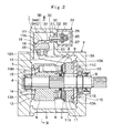
- Denoted at 16 is a tilting actuator which is provided in an actuator mount portion 3B in the main casing body 3. As shown in Figs. 2 and 3 , this tilting actuator 16 is largely constituted by cylinder bores 17A and 17B which are formed as tilting control cylinders in an actuator mount portion 3B of the main casing body 3 radially on the outer side of the cylinder block 6, and a servo piston 18 which is slidably fitted in the cylinder bores 17A and 17B. By the servo piston 18 of the tilting actuator 16, the swash plate 11 is driven into a tilted position either in the direction of arrow A or B.
- the servo piston 18 which constitutes a movable part of the tilting actuator 16.
- the servo piston 18 is in the form of a stepped piston having a large diameter portion 18A and a small diameter portion 18B.
- the large diameter portion 18A of the servo piston 18 is slidably received in the cylinder bore 17A in the actuator mount portion 3B, while the small diameter portion 18B is slidably received in the cylinder bore 17B.
- the large diameter portion 18A of the servo piston 18 defines a large-diameter pressure chamber 19A within the cylinder bore 17A, which is closed with a lid plate 20A from outer side of the cylinder bore 17A.
- the small diameter portion 18B of the servo piston 18 defines a small-diameter pressure chamber 19B within the cylinder bore 17B, which is closed with a lid plate 20B from outer side of the cylinder bore 17B.
- Denoted at 21 is an indented groove which is formed into the large diameter portion 18A of the servo piston 18.
- the indented groove 21 is in the form of a notched groove of U-shape in section, which is formed by notching part of an outer peripheral portion of the large diameter portion 18A.
- the indented groove 21 is located in a radially opposite position on the large diameter portion 18A relative to a coupling groove 22, which will be described hereinafter, across longitudinal axis 01-01 of the servo piston 18.
- the indented groove 21 is composed of a parallel groove portion 21A which is extended radially and perpendicularly relative to the longitudinal axis 01-01 of the servo piston 18, and a tapered groove portion 21B which is diverged in a tapered fashion from a proximal end of the parallel groove portion 21A.
- the parallel groove portion 21A of the indented groove 21 defines side wall portions 21A1 and 21A2 which extend parallel with each other in a direction perpendicular to the longitudinal axis 01-01 of the servo piston 18.
- the parallel groove portion 21A of the indented groove 21 is smaller in width (a measure in the axial direction of the servo piston 18).
- convexly curved plate portions 34B and 34C of an expansion spring 34 which will be described hereinafter, are engaged in a resiliently deformed state.
- the side wall portions 21A1 and 21A2 which stand opposingly across the width of the parallel groove portion 21A are held in abutting engagement with the convexly curved plate portions 34B and 34C of the expansion spring 34 to transmit axial displacements of the servo piston 18 to the expansion spring 34.
- the tapered groove portion 21B of the indented groove 21 is formed in a equilateral trapezoidal shape.
- the tapered groove portion 21B also has a function of preventing proximal portions of the expansion spring 34 (those portions other than the convexly curved plate portions 34B and 34C) from falling into contact or interference with side walls of the indented groove 21 when the servo piston 18 is displaced in an axial direction along the longitudinal axis O1-O1, as shown in Figs. 7 and 8 .
- the coupling groove 22 which is provided on the large diameter portion 18A of the servo piston 18.
- the coupling groove 22 is in the form of a parallel groove of U-shape in section and located in a radially opposite position from the indented groove 21 across the longitudinal axis 01-01.
- a slide plate 23, which will be described later on, is slidably mounted in the coupling groove 22 in order to transmit axial displacements of the servo piston 18 to the swash plate 11 through the tilting lever 12.
- the slide plate 23 which is slidably fitted in the coupling groove 22 on the servo piston 18.
- the slide plate 23 is constituted by a substantially rectangular plate which is slidable (capable of making a sliding displacement) in the coupling groove 22 in a direction transverse of the servo piston 18.
- the projection pin 12A of the tilting lever 12 is pivotally fitted in a fitting hole 23A which is bored at the center of the slide plate 23.
- the projection pin 12A of the tilting lever 12 is fitted in the fitting hole 23A of the slide plate 23 before placing the latter in the coupling groove 22 on the servo piston 18.
- an axial displacement of the servo piston 18 is transmitted from the slide plate 23 to the swash plate 11 through the tilting lever 12, so that the swash plate 11 is driven into a tilted position in the direction of arrow A or B following the movement of the servo piston 18.
- Denoted at 24 is a regulator which supplies and discharges a tilting control pressure to and from the tilting actuator 16.
- this regulator 24 is provided with a valve case 25 which is detachably attached to a lateral side portion of the actuator mount portion 3B.
- the valve case 25 is so located as to cover from outside the slot 3C which is provided in the actuator mount portion 3B of the main casing body 3.
- a control sleeve 26 is slidably received in a sleeve slide hole (not shown) which is formed in the valve case 25 of the regulator 24, and a spool 27 is slidably fitted in the control sleeve 26.
- the regulator 24 is arranged as a hydraulic servo valve having a spool 27 within the control sleeve 26.
- a valve spring 28 is provided at one end of the spool 27, while a hydraulic pilot portion 29 is provided at the other end of the spool 27.
- the hydraulic pilot portion 29 is connected to a pilot conduit 41 which will be described hereinafter.
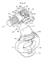
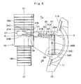
- control sleeve 26 is formed in a tubular shape having a longitudinal axis 02-02 substantially parallel with the longitudinal axis 01-01 of the servo piston 18. As shown in Figs. 4 to 6 , at one axial end, the control sleeve 26 is formed with an arcuate notched portion 26A on an outer peripheral surface for engagement with a coupling pin 33 which will be described hereinafter. Further, the control sleeve 26 is provided with three oil holes 26B, 26C and 26D which are bored radially at axially spaced positions between the notched portion 26A and the other axial end.
- control sleeve 26 is extended in the longitudinal direction of the axis 02-02, and displaced in the axial direction (for feedback control) by a feedback link 30 which will be described hereinafter.
- oil holes 26B, 26C and 26D in the control sleeve 26 are connected to tank 37, and control pressure conduits 38 and 39 which will be described later on.
- Denoted at 30 is the feedback link which is provided for feedback control of the regulator 24. As shown in Figs. 2 to 6 , this feedback link 30 is provided between the control sleeve 26 of the regulator 24 and the servo piston 18, constituting a feedback mechanism which feedback-controls the regulator 24 following tilting movements of the swash plate 11.
- the feedback link 30 is constituted by a link lever 31, a pivoting pin 32 as a support pin, coupling pin 33 and expansion spring 34, which will be described hereinafter. Further, as shown in Fig. 2 , the link lever 31 and expansion spring 34 are extended between the actuator mount portion 3B and the valve case 25 of the regulator 24 substantially in parallel relation with the tilting lever 12, and turned about the pivoting pin 32.
- the link lever which constitutes part of the feedback link 30.
- This link lever 31 is formed of steel or similar rigid material and in the shape of a stepped lever as shown in Figs. 4 to 8 .
- the link lever 31 is integrally provided with a pair of pin support portions 31A and 31B which are extended obliquely, so to say, in a bifurcated form toward opposite end portions of a coupling pin 33 which will be described hereinafter (see Fig. 5 ).
- the opposite end portions of the coupling pin 33 are fixed in the pin support portions 31A and 31B by press fit or other suitable means. Namely, the coupling pin 33 is fixedly supported by the pin support portions 31A and 31B at its opposite ends.
- a cylindrical head portion 31C is projected downward at and from the other longitudinal end of the link lever 31. Wrapped around and fixed to the head portion 31C is a bent portion 34A of the expansion spring 34, which will be described hereinafter. Further, a pin receptacle hole 31D is bored vertically through the link lever 31 at a longitudinally intermediate portion, and the pivoting pin 32 is passed through this pin receptacle hole 31D. Thus, through the pivoting pin 32, the link lever 31 is pivotally supported in the slot 3C of the actuator mount portion 3B.
- the link lever 31 is provided with a sensor mount hole 31E between the head portion 31C and the pin receptacle hole 31D, and a tilt angle sensor (not shown) is mounted in the sensor mount hole 31E.
- the tilt angle sensor is adapted to detect tilt angle of the swash plate 11 by detecting a turn angle of the link lever 31 by way of a testee body (not shown) which is fixed on a wall surface of the actuator mount portion 3B shown in Fig. 2 or fixed in other cooperative position.
- Designated at 33 is the coupling pin, the opposite ends of which are fixed in the pin support portions 31A and 31B of the link lever 31.
- This coupling pin 33 is supported by the pin support portions 31A and 31B of the link lever 31 at both ends, and its axially intermediate portion is put in and connected (engaged) with the notched portion 26A on the control sleeve 26 in a radial direction.
- the expansion spring a spring member which constitutes the feedback link 30 together with the link lever 31.
- This expansion spring 34 is formed by bending a longitudinally intermediate portion of a narrow metal leaf spring into substantially U-shape, so that the expansion spring 34 has a bent portion 34A of substantially U- or C-shape on the side of its base end.
- the expansion spring 34 is provided with a pair of convexly curved plate portions 34B and 34C which are formed with the same radius of curvature. These convexly curved plate portions 34B and 34C are provided on fore ends of bifurcated expansion arms which are spread away from each other in a forward direction.
- a pair of pin receptacle holes 34D are bored at transversely opposing portions of the bent portion 34A of the expansion spring 34.
- a stopper pin 35 is placed in the respective pin receptacle holes 34D and the head portion 31C thereby stopping rotational movements of the expansion spring 34 relative to the head portion 31C, while at the same time preventing the expansion spring 34 from coming off the head portion 31C.
- the convexly curved plate portions 34B and 34C of the expansion spring 34 are inserted into the indented groove 21 of the servo piston 18 from the side of the tapered groove portion 21B and engaged with (interposed between) the parallel groove portion 21A of the indented groove 21 in a resiliently flexed state.
- An axial displacement of the servo piston 18 is transmitted to the expansion spring 34 from the parallel groove portion 21A of the indented groove 21 through the convexly curved plate portions 34B and 34C.
- the link lever 31 which is integrally assembled with the expansion spring 34 is turned around the pivoting pin 32 following a displacement of the servo piston 18.
- a reference line K-K is drawn through the center of the pivoting pin 32 and in perpendicularly intersecting relation with the longitudinal axes 01-01 and 02-02 of the servo piston 18 and the control sleeve 26.
- the feedback link 30 which is composed of the link lever 31 and the expansion spring 34 is rocked about the pivoting pin 32 toward either side of the reference line K-K following the displacement of the servo piston 18.
- a pilot pump which constitutes a low-pressure oil source together with a tank 37.
- the pilot pump 36 takes in operating oil from the tank 37 and delivers a tilting control oil pressure (a tilting control pressure) to a control pressure conduit 38.
- control pressure conduit 38 is brought into and out of communication with another control pressure conduit 39, which is connected to the pressure chamber 19A of the tilting actuator 16.
- a low-pressure relief valve (not shown) or the like, the pressure of the pressure oil which is discharged from the pilot pump 36 is maintained at a pressure level which is low enough as compared with the discharge oil pressure of the hydraulic pump 1.
- a pilot pressure fed to the hydraulic pilot portion 29 becomes smaller than biasing force of the valve spring 28, the spool 27 of the regulator 24 is displaced to the right in Fig. 9 .
- the regulator 24 is changed over to a switched position (F) from a neutral position (E).
- the pilot pump 36 is connected to the pressure chamber 19A of the tilting actuator 16 through the control pressure conduits 38 and 39 to supply a tilting control pressure from the pilot pump 36 to the pressure chamber 19A.
- the spool 27 of the regulator 24 is displaced to the left in Fig. 9 .
- the regulator 24 is changed over to a switched position (G) from the neutral position (E).
- the control pressure conduit 39 is connected to the tank 37 to drain pressure oil into the tank 37 from the pressure chamber 19A of the tilting actuator 16, lowering the pressure chamber 19A to a pressure level which is almost as low as the tank pressure.
- control pressure conduit 40 is another control pressure conduit which is branched off the above-mentioned control pressure conduit 38. At a leading end, the control pressure conduit 40 is constantly connected to the pressure chamber 19B of the tilting actuator 16. This control pressure conduit 40 serves to supply the pressure chamber 19B with a tilting control pressure from the pilot pump 36.
- pilot conduit 41 which is branched off the above-mentioned control pressure conduit 38.
- This pilot conduit 41 is provided between the hydraulic pilot portion 29 of the regulator 24 and the pilot pump 36 to connect the discharge side of the pilot pump 36 to the hydraulic pilot portion 29 through a pressure control valve 42 which will be described hereinafter.
- Denoted at 42 is the pressure control valve which is provided in the course of the pilot conduit 41.
- This pressure control valve 42 is constituted by an electromagnetic control valve with an electromagnetic proportional solenoid 43.
- a pilot pressure to be supplied to the hydraulic pilot portion 29 of the regulator 24 is variably controlled by the electromagnetic proportional solenoid 43 of the pressure control valve 42.
- Indicated at 44 is a discharge conduit which is provided on the discharge side of the hydraulic pump 1, and, for example, its supply/discharge passage 15 on high pressure side, shown in Figs. 1 and 2 , is connected to an external actuator (not shown).
- a pressure sensor (not shown) is provided in the course of the discharge conduit 44 for detection of discharge pressure of the hydraulic pump 1.
- the electromagnetic proportional solenoid 43 of the pressure control valve 42 is supplied with a command signal indicative of the pressure in the discharge conduit 44.
- the pilot pressure to be supplied to the hydraulic pilot portion 29 of the regulator 24 is increased or reduced according to a command signal outputted to the electromagnetic proportional solenoid 43 (e.g., a pressure variation in the discharge conduit 44).
- the pilot pressure to be supplied from the pressure control valve 42 is increased as soon as a command signal for increasing the tilt angle of the swash plate 11 is applied to the electromagnetic proportional solenoid 43.
- the pilot pressure to the hydraulic pilot portion 29 of the regulator 24 is increased by the pressure control valve 42, and the spool 27 of the regulator 24 is displaced to the left against the action of the valve spring 28.
- the regulator 24 is changed over from the neutral position (E) to the switched position (G) to connect the control pressure conduit 39 to the tank 37.
- the movement of the servo piston 18 is transmitted to the control sleeve 26 of the regulator 24 through the feedback link 30.
- the feedback link 30 is displaced about the pivoting pin 32 in the direction of arrow C in Fig. 9 to put the control sleeve 26 in a sliding displacement in the same direction as the spool 27.
- a movement of the servo piston 8 is fed back to the regulator 24 by and through the feedback link 30.
- the control sleeve 26 is displaced in the direction of arrow C to return the regulator 24 to the neutral position (E).
- the displacement volume of the hydraulic pump 1 is controlled to deliver pressure oil at a large rate corresponding to the applied command signal.
- a tilting control pressure from the pilot pump 36 is supplied to the pressure chambers 19A and 19B of the tilting actuator 16.
- the servo piston 18 is put in a sliding displacement in the direction of arrow B according to a difference in pressure receiving area between the pressure chambers 19A and 19B, driving the swash plate 11 of the hydraulic pump 1 into a smaller tilt angle position.
- the movement of the servo piston 18 is fed back to the control sleeve 26 of the regulator 24 through the feedback link 30.
- the feedback link 30 is displaced about the pivoting pin 32 in the direction of arrow D in Fig. 9 to put the control sleeve 26 in a sliding displacement in the same direction as the spool 27.
- a movement of the servo piston 18 is fed back to the regulator 24 by and through the feedback link 30.
- the control sleeve 26 is displaced in the direction of arrow D to return the regulator 24 to the neutral position (E).
- the displacement volume of the hydraulic pump 1 is controlled to deliver pressure oil at a smaller rate corresponding to the applied command signal.
- the feedback link 30 operates in the manner as follows.
- this feedback link 30 is constituted by the link lever 31 formed of a rigid material and the expansion spring 34 formed of a spring material.
- the arcuate (convex) face of the other convexly curved plate portion 34C of the expansion spring 34 is continuously abutted against the side wall portion 21A2 of the parallel groove portion 21A. Therefore, the convexly curved plate portions 34B and 34C, formed in an arcuate shape, are resiliently abutted against the side wall portions 21A1 and 21A2 of the parallel groove portion 21A, without making rattling movements or opening up a gap space therebetween.
- the arcuate (convex) face of the convexly curved plate portion 34C of the expansion spring 34 is abutted against and smoothly engaged with the side wall portion 21A2 of the parallel groove portion 21A, permitting the link lever 31 to pick up an axial displacement of the servo piston 18 from the expansion spring 34 as a pushing force applied in the direction of arrow b through the side wall portion 21A2 of the indented groove 21.
- both of the convexly curved plate portions 34B and 34C are resiliently abutted against the side wall portions 21A1 and 21A2 of the parallel groove portion 21A, without making rattling movements or opening up a gap space therebetween.
- the convexly curved plate portions 34B and 34C which are provided on the bifurcated arms of the expansion spring 34 of the feedback link 30 are engaged in the parallel groove portion 21A of the indented groove 21 on the servo piston 18 in a resiliently deformed state. That is to say, the arcuate faces of the convexly curved plate portions 34B and 34C are resiliently abutted against the side wall portions 21A1 and 21A2 of the parallel groove portion 21A, respectively.
- the convexly curved plate portions 34B and 34C of the expansion spring 34 can be continuously kept in abutting engagement with the side wall portions 21A1 and 21A2 of the parallel groove portion 21A, preventing rattling movements which might otherwise occur therebetween.
- the convexly curved plate portions 34B and 34C of the expansion spring 34 are abutted against the side wall portions 21A1 and 21A2 of the indented groove 21 smoothly through the respective arcuate faces, so that the link lever 31 can pick up an axial displacement of the servo piston 18 in a stabilized manner.
- the feedback link 30 for transmitting a movement of the servo piston 18 to the control sleeve 26 of the regulator 24 is constituted by the link lever 31 formed of a rigid material and the expansion spring 34 formed of a spring material. Therefore, high frequency vibrations from the side of the servo piston 18 are attenuated by the spring action of the expansion spring 34 to prevent repeated minute vibrations which might otherwise occur to the link lever 31 of a rigid material.
- Such high frequency vibrations of the swash plate 11 are transmitted to the servo piston 18 of the tilting actuator 16 through the tilting lever 12 and the slide plate 23, and further to the feedback link 30 as minute vibrations. Therefore, damages to or impairment of the feedback link 30 may occur under the influence of the high frequency vibrations.
- the feedback link 30 is imparted with spring action, and above-mentioned high frequency vibrations can be attenuated by the expansion spring 34, preventing direct transmission of vibrations to the link lever 31 of a rigid material to ensure enhanced durability and prolonged service life of the link lever 31.
- the expansion spring 34 in the form of a leaf spring which constitutes part of the feedback link 30 to preclude possibilities of damages or impairment of the feedback link 30 which might occur as a result of repetitions of minute vibrations.
- the convexly curved plate portions 34B and 34C of the expansion spring 34 can be engaged in the indented groove 21 on the servo piston 18 free of rattling movements against the latter, precluding possibilities of plastic deformations of the expansion spring 34. Accordingly, axial displacements of the servo piston 18 can be picked up through the feedback link 30 over an extended period of time in a stable manner, stabilizing the displacement control over the hydraulic pump 1 with higher operational reliability.
- the bent portion 34A at one end of the expansion spring 34 is wrapped around the head portion 31C of the link lever 31 and fixed by the stopper pin 35, while the convexly curved plate portions 34B and 34C at the other end of the expansion spring 34 are held in abutting engagement with the parallel groove portion 21A in the indented groove 21 on the servo piston 18 in a resiliently deformed state. Therefore, the use of the expansion spring 34 of the above-described arrangements make it easier to alter the mounting direction of the feedback link 30 relative to the tilting actuator 16, increasing the degree of freedom in mounting the regulator 24 or other component parts.
- the present invention has been applied to a swash plate type hydraulic pump as a typical example of a swash plate type variable displacement hydraulic rotary machine.
- the present invention is not limited to the particular example shown.
- the present invention is similarly applicable to a swash plate type variable displacement hydraulic motor.
- the paired supply/discharge passages 14 and 15 in the foregoing embodiment are a pair of passages for supplying and discharging high pressure oil.
Landscapes
- Engineering & Computer Science (AREA)
- Mechanical Engineering (AREA)
- General Engineering & Computer Science (AREA)
- Reciprocating Pumps (AREA)
Applications Claiming Priority (2)
| Application Number | Priority Date | Filing Date | Title |
|---|---|---|---|
| JP2005157687 | 2005-05-30 | ||
| PCT/JP2006/308367 WO2006129431A1 (ja) | 2005-05-30 | 2006-04-14 | 可変容量型斜板式液圧回転機 |
Publications (2)
| Publication Number | Publication Date |
|---|---|
| EP1892413A1 true EP1892413A1 (de) | 2008-02-27 |
| EP1892413A4 EP1892413A4 (de) | 2012-11-21 |
Family
ID=37481364
Family Applications (1)
| Application Number | Title | Priority Date | Filing Date |
|---|---|---|---|
| EP06732175A Withdrawn EP1892413A4 (de) | 2005-05-30 | 2006-04-14 | Verstellbare hydraulische taumelscheibenrotationsmaschine |
Country Status (6)
| Country | Link |
|---|---|
| US (1) | US7814823B2 (de) |
| EP (1) | EP1892413A4 (de) |
| JP (1) | JP4625471B2 (de) |
| KR (1) | KR101036397B1 (de) |
| CN (1) | CN100494674C (de) |
| WO (1) | WO2006129431A1 (de) |
Cited By (5)
| Publication number | Priority date | Publication date | Assignee | Title |
|---|---|---|---|---|
| EP2679818A1 (de) * | 2012-06-28 | 2014-01-01 | Hydro Leduc | Hydraulische Pumpe mit Axialkolben, die in beide Drehrichtungen funktionieren |
| US9234532B2 (en) | 2008-09-03 | 2016-01-12 | Parker-Hannifin Corporation | Velocity control of unbalanced hydraulic actuator subjected to over-center load conditions |
| WO2017121545A1 (en) * | 2016-01-12 | 2017-07-20 | Danfoss Power Solutions Gmbh & Co Ohg | Swash plate angle sensor |
| EP3690229A1 (de) * | 2019-01-31 | 2020-08-05 | Eaton Intelligent Power Limited | Verschiebungssteuerung mit winkelsensoreinstellung |
| DE102023209572A1 (de) * | 2023-08-16 | 2025-02-20 | Robert Bosch Gesellschaft mit beschränkter Haftung | Schwenkwinkelmesseinrichtung an einer im Hubvolumen veränderlichen hydrostatischen Axialkolbenmaschine |
Families Citing this family (19)
| Publication number | Priority date | Publication date | Assignee | Title |
|---|---|---|---|---|
| DE102006062065A1 (de) * | 2006-12-29 | 2008-07-03 | Robert Bosch Gmbh | Axialkolbenmaschine mit einem einen radial erweiterten Innenraumabschnitt aufweisenden Gehäuse |
| JP2008196344A (ja) * | 2007-02-09 | 2008-08-28 | Hitachi Constr Mach Co Ltd | 可変容量型斜板式油圧ポンプ |
| JP4790767B2 (ja) * | 2008-07-16 | 2011-10-12 | 川崎重工業株式会社 | 斜板式液圧回転機 |
| US8333571B2 (en) * | 2008-12-12 | 2012-12-18 | Caterpillar Inc. | Pump having pulsation-reducing engagement surface |
| DE102009006288B4 (de) * | 2009-01-27 | 2019-06-19 | Robert Bosch Gmbh | Verstellvorrichtung einer hydrostatischen Maschine |
| JP5159717B2 (ja) * | 2009-07-06 | 2013-03-13 | 日立建機株式会社 | 可変容量型斜板式液圧回転機 |
| JP6749137B2 (ja) * | 2016-05-10 | 2020-09-02 | 川崎重工業株式会社 | 液圧回転機械の傾転角制御装置 |
| DE102016226039B3 (de) * | 2016-12-22 | 2018-02-08 | Danfoss Power Solutions Gmbh & Co. Ohg | Verdrängungssteueranordnung für eine axialkolbenpumpe |
| JP6913527B2 (ja) | 2017-06-22 | 2021-08-04 | 株式会社小松製作所 | 油圧ポンプおよびモータ |
| CN107498550B (zh) * | 2017-08-30 | 2023-12-22 | 歌尔科技有限公司 | 一种可自动紧接触的传动机构及机器人 |
| JP6745772B2 (ja) * | 2017-09-12 | 2020-08-26 | 日立建機株式会社 | 可変容量型斜板式液圧回転機 |
| CN107620702A (zh) * | 2017-10-10 | 2018-01-23 | 力源液压(苏州)有限公司 | 一种新型静液压支撑结构的斜盘 |
| KR102197623B1 (ko) * | 2018-12-19 | 2021-01-04 | 주식회사 모트롤 | 유압 펌프용 레귤레이터 |
| KR102198500B1 (ko) * | 2018-12-19 | 2021-01-05 | 주식회사 모트롤 | 유압 펌프용 레귤레이터 |
| JP2020180601A (ja) * | 2019-04-26 | 2020-11-05 | ナブテスコ株式会社 | 可変容量型油圧ポンプ及び建設機械 |
| US11644028B2 (en) * | 2020-04-08 | 2023-05-09 | Danfoss Power Solutions, Inc. | Control arrangement for variable displacement pump |
| DE102020210397B3 (de) * | 2020-08-14 | 2021-10-14 | Danfoss Power Solutions Gmbh & Co. Ohg | Hydrostatische servoeinheit |
| JP2024106426A (ja) * | 2023-01-27 | 2024-08-08 | 日立建機株式会社 | 可変容量型液圧回転機 |
| CN116221052B (zh) * | 2023-05-08 | 2023-07-04 | 石家庄凯林机械有限公司 | 矿用电动车辆变量泵控制装置 |
Family Cites Families (15)
| Publication number | Priority date | Publication date | Assignee | Title |
|---|---|---|---|---|
| US1572346A (en) * | 1924-08-12 | 1926-02-09 | John O Adsit | Drawing board |
| JPS5819246U (ja) * | 1981-07-31 | 1983-02-05 | 株式会社島津製作所 | クリツプ式変位計 |
| JPS6212273A (ja) | 1985-07-10 | 1987-01-21 | Matsushita Electric Ind Co Ltd | 画像読取装置 |
| US4970762A (en) * | 1989-03-06 | 1990-11-20 | Uni-Clip Corporation | Article securing device |
| JP2566530Y2 (ja) * | 1989-06-06 | 1998-03-30 | 九州日立マクセル 株式会社 | 電気接続子の保護具 |
| JPH0519771U (ja) * | 1991-07-26 | 1993-03-12 | 株式会社佐久間製作所 | 固定機構 |
| JP3354979B2 (ja) * | 1992-12-22 | 2002-12-09 | 日立建機株式会社 | 可変容量型液圧回転機 |
| DE19538835C1 (de) * | 1995-10-18 | 1997-03-13 | Brueninghaus Hydromatik Gmbh | Axialkolbenmaschine mit Querverstellung und Drehverstellung der Schwenkwiege |
| CN1154442A (zh) * | 1995-11-24 | 1997-07-16 | 株式会社丰田自动织机制作所 | 变量式压缩机 |
| US6413055B1 (en) * | 2001-02-02 | 2002-07-02 | Sauer-Danfoss Inc. | Swashplate position assist mechanism |
| JP2003074461A (ja) * | 2001-09-03 | 2003-03-12 | Hitachi Constr Mach Co Ltd | 可変容量型液圧回転機および該液圧回転機の組立方法 |
| JP2003074460A (ja) * | 2001-09-03 | 2003-03-12 | Hitachi Constr Mach Co Ltd | 可変容量型液圧回転機 |
| JP2003269324A (ja) * | 2002-03-12 | 2003-09-25 | Hitachi Constr Mach Co Ltd | 可変容量型斜板式油圧ポンプ |
| JP2004278413A (ja) * | 2003-03-17 | 2004-10-07 | Hitachi Constr Mach Co Ltd | 可変容量型斜板式油圧ポンプ |
| DE102005059808B3 (de) * | 2005-12-14 | 2007-06-14 | Sauer-Danfoss Gmbh & Co Ohg | Axialkolbenmaschine mit einer Verstelleinheit zur elektrisch proportionalen Verstellung des Fördervolumens |
-
2006
- 2006-04-14 KR KR1020067026170A patent/KR101036397B1/ko not_active Expired - Lifetime
- 2006-04-14 WO PCT/JP2006/308367 patent/WO2006129431A1/ja not_active Ceased
- 2006-04-14 EP EP06732175A patent/EP1892413A4/de not_active Withdrawn
- 2006-04-14 JP JP2006544153A patent/JP4625471B2/ja not_active Expired - Lifetime
- 2006-04-14 CN CNB2006800010399A patent/CN100494674C/zh not_active Expired - Lifetime
- 2006-04-14 US US11/632,422 patent/US7814823B2/en active Active
Cited By (8)
| Publication number | Priority date | Publication date | Assignee | Title |
|---|---|---|---|---|
| US9234532B2 (en) | 2008-09-03 | 2016-01-12 | Parker-Hannifin Corporation | Velocity control of unbalanced hydraulic actuator subjected to over-center load conditions |
| EP2679818A1 (de) * | 2012-06-28 | 2014-01-01 | Hydro Leduc | Hydraulische Pumpe mit Axialkolben, die in beide Drehrichtungen funktionieren |
| FR2992691A1 (fr) * | 2012-06-28 | 2014-01-03 | Hydro Leduc | Pompe hydraulique a pistons axiaux pouvant fonctionner dans les deux sens de rotation |
| WO2017121545A1 (en) * | 2016-01-12 | 2017-07-20 | Danfoss Power Solutions Gmbh & Co Ohg | Swash plate angle sensor |
| US10801492B2 (en) | 2016-01-12 | 2020-10-13 | Danfoss Power Solutions G.m.b.H. & Co. OHG | Swash plate angle sensor |
| EP3690229A1 (de) * | 2019-01-31 | 2020-08-05 | Eaton Intelligent Power Limited | Verschiebungssteuerung mit winkelsensoreinstellung |
| US11608825B2 (en) | 2019-01-31 | 2023-03-21 | Danfoss Power Solutions Ii Technology A/S | Displacement control with angle sensor adjustment |
| DE102023209572A1 (de) * | 2023-08-16 | 2025-02-20 | Robert Bosch Gesellschaft mit beschränkter Haftung | Schwenkwinkelmesseinrichtung an einer im Hubvolumen veränderlichen hydrostatischen Axialkolbenmaschine |
Also Published As
| Publication number | Publication date |
|---|---|
| EP1892413A4 (de) | 2012-11-21 |
| CN101044318A (zh) | 2007-09-26 |
| US20080041223A1 (en) | 2008-02-21 |
| KR101036397B1 (ko) | 2011-05-23 |
| WO2006129431A1 (ja) | 2006-12-07 |
| JP4625471B2 (ja) | 2011-02-02 |
| CN100494674C (zh) | 2009-06-03 |
| US7814823B2 (en) | 2010-10-19 |
| JPWO2006129431A1 (ja) | 2008-12-25 |
| KR20080008203A (ko) | 2008-01-23 |
Similar Documents
| Publication | Publication Date | Title |
|---|---|---|
| US7814823B2 (en) | Feedback link for swash plate-type variable displacement hydraulic rotary machine | |
| KR20190132213A (ko) | 유압 펌프 | |
| US20200011308A1 (en) | Servo regulator | |
| EP3943751B1 (de) | Pumpenleistungsregler | |
| KR101596560B1 (ko) | 서보 레귤레이터 | |
| EP0793018B1 (de) | Neigungswinkelstellvorrichtung für eine taumelscheibenpumpe | |
| KR102328899B1 (ko) | 가변 용량형 유압 장치 | |
| JP4997162B2 (ja) | サーボレギュレータ | |
| JP7051475B2 (ja) | 油圧ポンプ | |
| JP5204531B2 (ja) | サーボレギュレータ | |
| EP1760313A1 (de) | Hydraulische schrägscheiben-rotationsmaschine mit variabler verdrängung | |
| JP4551575B2 (ja) | 斜板型ピストンポンプ | |
| CN110431305B (zh) | 伺服调节器 | |
| JP2021173246A (ja) | 流体圧駆動装置 | |
| JP2003074461A (ja) | 可変容量型液圧回転機および該液圧回転機の組立方法 | |
| JPH08200208A (ja) | 斜板式ピストンポンプ・モータ装置 | |
| JP2003074460A (ja) | 可変容量型液圧回転機 | |
| JP6745772B2 (ja) | 可変容量型斜板式液圧回転機 | |
| JP2009243409A (ja) | サーボレギュレータ | |
| JP2003269324A (ja) | 可変容量型斜板式油圧ポンプ | |
| JP2021017846A (ja) | 流体機械及び建設機械 | |
| KR102897679B1 (ko) | 유체 기계 및 건설 기계 | |
| JP2009052664A (ja) | サーボレギュレータ | |
| JP2023131814A (ja) | 液圧回転機 | |
| JP2023178382A (ja) | 油圧ポンプ及び建設機械 |
Legal Events
| Date | Code | Title | Description |
|---|---|---|---|
| PUAI | Public reference made under article 153(3) epc to a published international application that has entered the european phase |
Free format text: ORIGINAL CODE: 0009012 |
|
| 17P | Request for examination filed |
Effective date: 20080102 |
|
| AK | Designated contracting states |
Kind code of ref document: A1 Designated state(s): DE FR GB IT SE |
|
| DAX | Request for extension of the european patent (deleted) | ||
| RBV | Designated contracting states (corrected) |
Designated state(s): DE FR GB IT SE |
|
| A4 | Supplementary search report drawn up and despatched |
Effective date: 20121024 |
|
| RIC1 | Information provided on ipc code assigned before grant |
Ipc: F04B 1/22 20060101AFI20121019BHEP |
|
| STAA | Information on the status of an ep patent application or granted ep patent |
Free format text: STATUS: EXAMINATION IS IN PROGRESS |
|
| 17Q | First examination report despatched |
Effective date: 20180301 |
|
| STAA | Information on the status of an ep patent application or granted ep patent |
Free format text: STATUS: THE APPLICATION IS DEEMED TO BE WITHDRAWN |
|
| 18D | Application deemed to be withdrawn |
Effective date: 20180712 |