EP1890915B1 - Module de coussin gonflable de securite - Google Patents
Module de coussin gonflable de securite Download PDFInfo
- Publication number
- EP1890915B1 EP1890915B1 EP06742409A EP06742409A EP1890915B1 EP 1890915 B1 EP1890915 B1 EP 1890915B1 EP 06742409 A EP06742409 A EP 06742409A EP 06742409 A EP06742409 A EP 06742409A EP 1890915 B1 EP1890915 B1 EP 1890915B1
- Authority
- EP
- European Patent Office
- Prior art keywords
- airbag module
- airbag
- module according
- gas
- orifice
- Prior art date
- Legal status (The legal status is an assumption and is not a legal conclusion. Google has not performed a legal analysis and makes no representation as to the accuracy of the status listed.)
- Expired - Fee Related
Links
- 238000002347 injection Methods 0.000 claims description 19
- 239000007924 injection Substances 0.000 claims description 19
- 238000006073 displacement reaction Methods 0.000 claims description 6
- 239000007789 gas Substances 0.000 description 158
- 230000002093 peripheral effect Effects 0.000 description 6
- 238000012986 modification Methods 0.000 description 4
- 230000004048 modification Effects 0.000 description 4
- 230000014759 maintenance of location Effects 0.000 description 3
- 208000027418 Wounds and injury Diseases 0.000 description 2
- 230000006978 adaptation Effects 0.000 description 2
- 230000006378 damage Effects 0.000 description 2
- 238000013461 design Methods 0.000 description 2
- 208000014674 injury Diseases 0.000 description 2
- 230000001133 acceleration Effects 0.000 description 1
- 230000000712 assembly Effects 0.000 description 1
- 238000000429 assembly Methods 0.000 description 1
- 238000007664 blowing Methods 0.000 description 1
- 238000013016 damping Methods 0.000 description 1
- 230000001419 dependent effect Effects 0.000 description 1
- 238000001514 detection method Methods 0.000 description 1
- 238000007599 discharging Methods 0.000 description 1
- 238000005516 engineering process Methods 0.000 description 1
- 230000001771 impaired effect Effects 0.000 description 1
- 239000000463 material Substances 0.000 description 1
- 230000000452 restraining effect Effects 0.000 description 1
- 238000000926 separation method Methods 0.000 description 1
- 238000012360 testing method Methods 0.000 description 1
- 230000036962 time dependent Effects 0.000 description 1
- 238000013519 translation Methods 0.000 description 1
- 238000009423 ventilation Methods 0.000 description 1
- 238000013022 venting Methods 0.000 description 1
Images


Classifications
-
- B—PERFORMING OPERATIONS; TRANSPORTING
- B60—VEHICLES IN GENERAL
- B60R—VEHICLES, VEHICLE FITTINGS, OR VEHICLE PARTS, NOT OTHERWISE PROVIDED FOR
- B60R21/00—Arrangements or fittings on vehicles for protecting or preventing injuries to occupants or pedestrians in case of accidents or other traffic risks
- B60R21/02—Occupant safety arrangements or fittings, e.g. crash pads
- B60R21/16—Inflatable occupant restraints or confinements designed to inflate upon impact or impending impact, e.g. air bags
- B60R21/26—Inflatable occupant restraints or confinements designed to inflate upon impact or impending impact, e.g. air bags characterised by the inflation fluid source or means to control inflation fluid flow
- B60R21/276—Inflatable occupant restraints or confinements designed to inflate upon impact or impending impact, e.g. air bags characterised by the inflation fluid source or means to control inflation fluid flow with means to vent the inflation fluid source, e.g. in case of overpressure
-
- B—PERFORMING OPERATIONS; TRANSPORTING
- B60—VEHICLES IN GENERAL
- B60R—VEHICLES, VEHICLE FITTINGS, OR VEHICLE PARTS, NOT OTHERWISE PROVIDED FOR
- B60R21/00—Arrangements or fittings on vehicles for protecting or preventing injuries to occupants or pedestrians in case of accidents or other traffic risks
- B60R21/02—Occupant safety arrangements or fittings, e.g. crash pads
- B60R21/16—Inflatable occupant restraints or confinements designed to inflate upon impact or impending impact, e.g. air bags
- B60R21/23—Inflatable members
- B60R21/239—Inflatable members characterised by their venting means
-
- B—PERFORMING OPERATIONS; TRANSPORTING
- B60—VEHICLES IN GENERAL
- B60R—VEHICLES, VEHICLE FITTINGS, OR VEHICLE PARTS, NOT OTHERWISE PROVIDED FOR
- B60R21/00—Arrangements or fittings on vehicles for protecting or preventing injuries to occupants or pedestrians in case of accidents or other traffic risks
- B60R21/02—Occupant safety arrangements or fittings, e.g. crash pads
- B60R21/16—Inflatable occupant restraints or confinements designed to inflate upon impact or impending impact, e.g. air bags
- B60R21/26—Inflatable occupant restraints or confinements designed to inflate upon impact or impending impact, e.g. air bags characterised by the inflation fluid source or means to control inflation fluid flow
- B60R21/276—Inflatable occupant restraints or confinements designed to inflate upon impact or impending impact, e.g. air bags characterised by the inflation fluid source or means to control inflation fluid flow with means to vent the inflation fluid source, e.g. in case of overpressure
- B60R2021/2765—Inflatable occupant restraints or confinements designed to inflate upon impact or impending impact, e.g. air bags characterised by the inflation fluid source or means to control inflation fluid flow with means to vent the inflation fluid source, e.g. in case of overpressure comprising means to control the venting
Definitions
- the invention relates to an airbag module for a motor vehicle according to the preamble of claim 1.
- the document DE 101 39 626 A1 Shows this Gattunssnduenden state of technology
- the invention has for its object to improve the inflation of an airbag module of the type mentioned.
- the airbag module has a first outflow opening, which is associated with at least one movable element between two positions by the movement between the two positions, the first outflow opening is gas-conductively connected to the gas outlet opening of the gas generator such that the gas flowing out through the gas outlet opening at least partially is directed to the outside space.
- a gas quantity with which the gas bag is filled can be adapted to the respective accident situation.
- an oop situation for example, ie, a person to be protected by the gas bag is eg along a main deployment direction of the gas bag is not sufficiently removed from the gas bag, thus early the first discharge opening can be opened so that the person to be protected is not injured by a too inflated airbag.
- the gas outlet opening of the gas generator can be connected in a gas-conducting manner to the first outflow opening such that the gas flowing out through the gas outlet opening is conducted completely into the outer space surrounding the airbag module.
- inflation of the gas bag for example, in the case of an oop situation can be completely prevented.
- the invention provides for a cover of the airbag module, which covers the airbag and separates an interior of the airbag module from an outer space surrounding the airbag module.
- a cover may be, for example, a cover of a hub body of the steering wheel.
- the cover has an openable area through which the gas bag can be deployed into the exterior space of the airbag module.
- the openable area may have tear lines along which the openable area of the cover ruptures due to the deploying gas bag pressing against the cover when inflated along a main deployment direction.
- the second outflow opening is arranged in the interior of the airbag module such that the gas passes through the openable area into the exterior space.
- a risk of injury to a person does not exist here, since the openable area is covered by the unfolding gas bag.
- the movable element is mounted in the airbag module such that it is displaceable in a direction of movement parallel to the main deployment direction of the airbag.
- the movable element is preferably mounted such that it is displaceable and / or rotatable in a direction of movement extending parallel to the injection opening.
- the airbag module has a chamber which surrounds the gas generator of the airbag module.
- the chamber serves to protect the gas bag and, on the other hand, has openable (closable) outflow openings (for introducing gas into the exterior space) or outflow opening (for introducing gas into the gas bag) or can form such outflow openings by movements of components of the chamber.
- the movable element is formed at least by the gas generator, wherein preferably the gas generator is fixed to the chamber such that the first outflow opening is opened by a movement of the gas generator along the direction of movement.
- the gas generator is designed such that the movement of the gas generator along the direction of movement is effected by a pressure generated during the outflow of the gas.
- the chamber surrounding the gas generator is formed at least by a first and a second chamber member, wherein one of the two chamber elements is connected to the gas generator, and wherein the two chamber elements form a receptacle for the gas generator and are movably mounted to each other along the direction of movement, so that They can be moved away from each other along the direction of movement of the gas generator, whereby the first Outflow opening, for example, in the form of a gap surrounding the gas generator to the chamber, that is, between two mutually along the direction of movement facing circumferential edges of the two chamber elements is formed.
- the two chamber elements are preferably mounted so as to be movable relative to one another via guide elements extending along the direction of movement.
- guide elements may for example be integrally connected to one of the two chamber elements and protrude along the direction of movement of this chamber element or another component of the chamber.
- the other chamber member may then have recesses (e.g., through holes) into which these guide members engage so that this other chamber member is movably supported along the direction of travel on the guide members, i.e., the guide members slide through the recesses.
- the gas bag is fixed to the first chamber element, while the gas generator is fixed to the second chamber element.
- the first chamber element, to which the gas bag is attached is arranged along the main deployment direction of the gas bag between the second chamber element and a driver to be protected by the gas bag.
- the gas generator is attached to the second chamber member, that this is spaced by movement of the gas generator along the direction of movement of the gas generator from the first chamber element, wherein along the direction of movement between the two chamber elements, the first outflow opening, for example in the form of a gas generator across to the movement direction circumferential gap forms. That is, the first outflow opening is opened by this movement apart of the two chamber elements.
- a releasable locking element which serves for fixing the gas generator.
- This can fix the gas generator in its initial position when inflating the airbag and can be controlled by control electronics, so that depending on a specific accident situation at a certain time unlocking of the locking element can be done.
- the gas generator which arises due to the gas flowing out Pressure against the locking member, after releasing or unlocking the locking member, following the pressure, moves along the direction of travel away from the inflation opening of the airbag to a further position spaced along the direction of travel from the initial position.
- the locking element is designed such that it can be brought into engagement with the guide elements for securing the gas generator (the locking element can, for example, engage in a form-fitting manner on the guide elements).
- the locking element is configured and provided to be brought at least partially out of engagement with the guide elements by a linear movement along a transverse to the direction of movement of the gas generator unlocking.
- the locking element in this case along the unlocking longitudinally extended, the unlocking along the direction of movement piercing slots on which engage the guide elements to set the generator.
- these elongated holes can widen along the unlocking direction, wherein the guide elements along the direction of movement in expanded portions of these slots are insertable and have notches, in which the locking element, with edge regions that bound the slots at their respective narrow areas, so intervene in that the guide elements press against these edge regions along the direction of movement and are therefore fixed along the direction of movement.
- a narrow and an expanded region of an oblong hole opposite the direction of unlocking can be separated from one another by a constriction or narrowing of the oblong hole transversely to the unlocking direction.
- This is advantageous, since in this way a guide element with its annular circumferential notch can be pressed into the narrow region and is held there by the constriction. Moving a guide element located in a narrow area along the unlocking direction into a widened region of a slot thus presupposes a predefinable minimum force and thus reduces the risk of unintentional unlocking of the locking element.
- a movement generating device which generates the linear movement of the locking element for releasing the locking element.
- this movement-generating device preferably has a piston which presses against the locking element along the unlocking direction, wherein the guide elements are displaced from the narrow areas of the elongated holes into the widened areas of these elongated holes so that they extend transversely to the unlocking direction, i. h., Can slide along the direction of movement in the slots.
- At the locking elements can be formed along the direction of travel broadening, so that the locking element when sliding along the guide elements not completely disengaged from the guide elements. Thus, there is a maximum possible distance between the two chamber elements along the direction of movement.
- the first outflow opening or a plurality of such first outflow openings is formed on a chamber surrounding the gas generator, the gas generator having a fixed position with respect to the injection opening (with the exception of compensating movements which are possible by means of a vibratory mounting of the gas generator).
- the movable element is mounted so movably on this chamber, that the first outflow opening by means of the movable element can be closed or opened.
- the chamber of the gas generator has a cylindrical wall in which the first outflow opening is arranged.
- this cylindrical wall can rotate the gas generator transversely to the main deployment direction of the gas bag of the airbag module.
- the gas outlet opening of the gas generator (or a plurality of such gas outlet openings) of the first outflow opening (or a corresponding plurality of such first outflow openings) transverse to the main deployment direction of the airbag, so that the gas initially flow out transversely to the main deployment direction from the chamber surrounding the gas generator can.
- the movable member has a cylindrical ring with a recess, the ring being displaceable on the wall of the chamber is mounted, that the recess by a displacement of the ring along the wall with the first outflow opening can be brought into coincidence.
- the recess of the ring may have the shape and size of the first outflow opening.
- the cylindrical ring has a corresponding plurality of recesses, which can be brought into coincidence by a displacement of the ring along the wall with these first outflow openings.
- the recess (or recesses) of the ring are formed on the ring so that the ring is rotatable with respect to the wall of the chamber to a position in which the ring completely closes the first outflow opening (or the plurality of first outflow openings) , Likewise, the recesses may be arranged on the ring, that in a certain position of the ring with respect to the wall, all first outflow openings of the wall are open.
- the ring for moving the ring along the direction of movement has a recess with an edge extending transversely to the direction of movement (in a cylindrical wall, the direction of movement preferably rotates the cylindrical wall transversely to the main deployment direction of the airbag, i.e. transverse to the cylindrical axis of the cylindrical wall).
- this recess is formed as a gap interrupting the ring (open ring), which extends transversely to the direction of movement.
- a piston of a movement generating device pushes along the direction of movement against the edge of the recess, so that the ring is pushed by the piston from an initial position in which the first outflow opening is closed by the ring in a further position in which the first outflow opening is open.
- This advantageous tangential force introduction of the ring is only slightly deformed.
- the recess may be formed only partially on the ring, that is, not completely cut through the ring perpendicular to the direction of movement. In this case further preferred is a narrow, the ring Transversely to the direction of separation by further cutting provided, which is formed in the direction of movement behind the edge of the recess and along this edge, ie, transverse to the direction of movement extends.
- the recess of the ring which can be brought to cover the first outflow opening with the first outflow opening in cover, fail due to the minimization of the deformation of the ring particularly large area.
- the recess (or the recesses) may therefore occupy about half of the wall of the chamber facing surface of the ring.
- the chamber surrounding the gas generator has a closable discharge opening through which gas generated or released by the gas generator can flow into the gas bag for inflating the gas bag.
- the outflow opening (this can also be a plurality of outflow openings) is arranged on a discharge area of the chamber facing the injection opening of the airbag.
- the movable element of the airbag module has a valve plate with an opening, wherein the valve plate is movably mounted on the wall of the chamber such that the opening can be brought into coincidence with the outflow opening by displacing (rotating) the valve plate along the outflow region.
- a corresponding plurality of openings is provided on the valve plate, which can be brought into coincidence with the outflow openings by displacement or rotation of the valve plate, whereby the outflow openings of the chamber can be opened.
- the opening or the openings are formed on the valve plate, that the valve plate by turning the valve plate with respect to the outflow area closes all outflow openings of the discharge area of the chamber by a predeterminable angle.
- valve plate is fixed to a peripheral, the airbag or the inflation opening of the airbag facing edge of the ring. That is, the movable member may be formed as a flat cylinder open on one side, the ring forming the cylinder wall, and the one bottom of this cylinder being formed by the (circular) valve plate.
- the opening of the valve plate is arranged with respect to the recess of the ring, that the outflow opening is closed by the valve plate when the first outflow opening of the wall of the chamber is open, further preferably, the outflow opening is open when the first outflow opening closed by the ring is.
- the additionally provided controllable outflow openings of the chamber are advantageous because not only an additional flow path for pressure relief of the airbag is made possible, but the way of the gases in the airbag can be completely blocked, so that a further reduction of the occupant load under oop conditions is possible.
- the gas bag has a second outflow opening (or a corresponding plurality of second outflow openings) which, in an inflated state of the gas bag, is arranged in the interior of the airbag module such that gas emerging from the second outflow opening passes through the apparent area of the airbag module Cover of the airbag module can pass into the outer space surrounding the airbag module.
- means are provided which are designed and arranged to prevent the gas emerging from the first and second outflow openings from flowing in the opposite direction to the main deployment direction H.
- the gas bag has a third outlet opening for discharging gas, which is arranged in the case of a deployed gas bag in the outer space of the airbag module.
- Such third outflow apertures are advantageous in that they provide reliable venting of the stagnant, i. already deployed airbag, allow.
- the third outflow opening in the inflated state of the airbag at a side facing the airbag module i. a side facing away from the driver of the airbag, arranged so that the gases flowing from the gas bag are not directed directly or untwisted to the driver or a person to be protected by the gas bag.
- a further third outflow opening is provided, which serves for the discharge of gas and is arranged in an unfolded airbag in the outer space of the airbag module.
- the further third outflow opening preferably lies in the inflated state of the airbag transverse to the main deployment direction of the airbag of the third outflow opening, so that, for example, in a symmetrically constructed driver's airbag as symmetrical Gasabstrahl is effected and the airbag (spatial) can be evenly vented.
- the first, second and third outflow openings can be combined and matched to one another.
- the second and third outflow openings in the gas bag replace the standard outflow openings with which an airbag is usually equipped.
- the matching of the area of the second outflow openings with respect to the third outflow openings, i. the coordination of the ratio of these two surfaces to each other, takes place in such a way that the so-called in-position performance (the airbag can unfold freely and unhindered) corresponds to that of a known standard airbag.
- the first outflow openings are switchable or controllable. That is, opening this first Outflow openings are time-dependent after ignition of the gas generator (for example, by a pyrotechnic movement generating device). With an early opening of these first outflow openings, the mass flow of the gas generator below a gas bag connection (for example, by clamping the inflation of the airbag peripheral edge region on a generator support) blown off and thus affects the degree of filling of the airbag, at the same time by additional second and third outlet more effective retention performance ("softer" gas bag) for lighter passengers (5% woman) is achieved.
- the retention performance of heavy occupants (50% and 95% man) is improved.
- the unfolding of the airbag can be assisted by a better rectangular identification of the acceleration values (deceleration) of a vehicle occupant in the event of an accident situation triggering the airbag module (early retention by rapid provision of airbag).
- Overall can be adjusted depending on the occupant by the selectively selectable time of the opening of the additional outflow surface (first outflow) optimal damping of the airbag.
- the determination of the opening time can be made automatically by means of an occupant sensor (size, weight, position) as well as a detection of crash-dependent data (deceleration, speed).
- the gases conducted into the airbag module are not guided further down through openings of a generator carrier, ie into the steering wheel body along the steering axis, but are deflected along the steering axis or the main deployment direction of the airbag in the direction of the openable region of the cover of the airbag module , The exit of the gases thus takes place along the airbag through the openable area of the cover. Since even in an oop situation, the body parts close to the airbag module of an occupant are sufficiently covered by the gas bag, injuries due to the hot gases that have flowed out are ruled out. In addition, through the flow path described above through the openable area of the cover, there are no adjacent assemblies impaired. Additional measures on the steering wheel to ensure the outflow are therefore not necessary. At the same time prevents, for example, the hands are damaged on the steering wheel, as would be possible, for example, in a flow through the steering wheel.
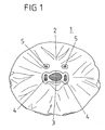
- FIG. 1 shows an airbag 1, which is designed for use as a driver's gas bag (driver's airbag).
- the airbag 1 is spread along an extension plane coincident with the paper plane and is made of two circular Gas bag layers whose peripheral edges are sewn together, glued, woven or welded to form the gas bag.
- the gas bag 1 has a side 2, which in an inflated state of the airbag 1 in the FIG. 1 Is facing airbag module 6, not shown, or a driver who is to be protected by the inflated airbag 1, facing away.
- an injection opening 3 is centrally provided in the form of a circular opening, can be introduced through the gas for inflating the airbag 1 in the airbag 1.
- the gas bag 1 has two second outflow openings 4 which are formed on two mutually opposite edge regions of the injection opening 3 and extend along the injection opening 3 along. These two second outflow openings 4 are arranged adjacent to the injection opening 3 such that they are arranged in the inflated state of the airbag 1 in an interior 1 of the airbag module 6.
- the gas bag 1 has third outflow openings 5, which each have a distance to the center of the circular injection opening 3, which is greater than the distance of the second outflow openings 4 to the center of the injection opening 3, wherein this distance is formed so large that the third outflow openings 5 in an inflated state of the airbag 1 outside of the inner space I of the airbag module 6, in which the outer space A surrounding the airbag module are arranged.
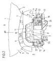
- FIG. 2 shows in connection with FIGS. 3 to 7 a partially sectioned view of the airbag module 6, which has a cover 7, which forms a receptacle for the airbag 1 of the airbag module 6 and for a gas generator 8 and a gas generator 8 surrounding chamber 9 of the airbag module 6.
- the cover 7 of the airbag module 6 separates the inner space 1 from the outer space A of the airbag module 6.
- an openable area 10 is further provided, which tears, for example, along predefined tear lines, when the gas bag 1 as a result of the building up in the gas bag 1 gas pressure along a main deployment direction of the airbag from the interior I against the openable area 10 of the cover 7 of the airbag module 6 presses.
- Under the interior I is understood to mean the space occupied by the gas bag 8 in its deflated state.
- the interior I is bounded by the unopened cover 7.
- FIG. 2 shows the airbag module 6, after the gas bag 1 (in FIG. 2 shown in section) through the openable area 10 of the cover 7 has spread out into the outer space A of the airbag module 6, wherein the third outflow openings 5 of the airbag 1 are arranged in the outer space A and the second outflow openings 4 in the interior I of the airbag module 6 are arranged.
- the flow path is in the FIG. 2 schematically indicated by corresponding arrows.
- While the gas present in the gas bag 1 can flow directly into the outer space A through the third outflow opening 5, the gas is introduced through the second outflow opening 4 first into the interior I and from there along the gas bag 1 through the openable area 10 into the exterior space A. initiated.
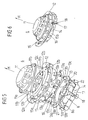
- the chamber 9 surrounding the gas generator 8 is formed by a cap-shaped diffuser 11, a generator support 12, a bottom plate 13 and a support 14 for the gas generator 8 mounted thereon in a manner capable of oscillating.
- the diffuser 11 is cap-shaped and protrudes along the main deployment direction H through the inflation opening 3 into the (inflated) gas bag 1, wherein an edge region surrounding the inflation opening 3 of the airbag 1 along the Hauptentfaltungsraum H of the airbag between a peripheral edge region 11a of the diffuser 11 and a circumferential edge region 12a, which surrounds a central opening 12c of the generator support 12 facing the injection opening 3, and is clamped between these two edge regions 11a, 12a facing one another along the main deployment direction H (gas bag clamping).
- the diffuser 11 and the generator support 12 are projected longitudinally along the main deployment direction H from the edge portion 11a of the diffuser 11 (the four fixing members 11b are arranged along the annular edge portion 11a equidistant to the respective nearest neighbor along the edge portion 11a).
- These four fasteners 11b are through corresponding holes 12 b, which are formed on the edge region 12 a of the generator support 12, out, so that free end portions of these fastening elements 11 b protrude from a side facing away from the diffuser 11 of the edge region 12 a of the generator support 12.
- the bottom plate 13 has a central circular gas generator recess 13 c, which lies along the main deployment direction H of the central opening 12 c of the generator support 12 and the injection port 3 of the airbag 1 opposite.
- this gas generator recess 13 c of the bottom plate 13 of the substantially cylindrical gas generator 8 is introduced along the main deployment direction H.
- the gas generator 8 is connected via a projecting from the gas generator 8 transversely to the main deployment direction H flange 8 a, which circulates the gas generator 8 transversely to the main deployment direction H, vibrationally connected to a trough-shaped carrier 14.
- a vibratory connection of the gas generator 8 via the flange 8a to the carrier 14 is not absolutely necessary.
- the flange 8a itself can be formed as a carrier 14, so that the carrier 14 and the gas generator 8 are connected directly to each other.
- the carrier 14 is fixed to free ends of the end portions of the fastening means 11 b, which are guided through the holes 13 a of the bottom plate 13, and closes the chamber 9 of the gas generator 8 at a side opposite to the diffuser 11 along the main deployment direction H.
- the generator support 12 furthermore has a cylindrical wall 15 which is oriented perpendicular to the central opening 12c of the generator support 12 and which rotates annularly around the central opening 12b of the generator support 12 transversely to the main deployment direction H.
- a plurality of first outflow openings 15a are formed, which can be closed or opened by means of a movable element in the form of a cylindrical ring 16.
- the cylindrical ring 16 is formed such that it bears against an inner side of the cylindrical wall 15 facing the gas generator 8 and is displaceable between two positions along a direction of movement B extending transversely to the main deployment direction H, which rotates the cylindrical wall 15 transversely to the main deployment direction H. That is, the cylindrical ring 16 can be rotated about its cylinder axis coincident with the main deployment direction H.
- Recesses 16a of the shape of the outflow openings 15a of the wall 15 are provided on the ring 16, which are arranged along the cylindrical ring 16 such that they can be completely brought into coincidence with the first outflow openings 15a of the wall 15.
- the first outflow openings 15a are fully open, so that provided by the gas generator 8 gases can pass through the first outflow openings 15a in the interior I and from there into the outer space A of the airbag module 6.
- the recesses 16a of the ring 16 can be brought out of register with the first outflow openings 15a of the wall 15 of the generator carrier 12. In this case, the first outflow openings 15 a are completely closed by the ring 16.
- a motion-generating device 17 is arranged on the bottom plate 13 FIG. 7 provided in the form of a pyrotechnic actuator.
- the movement generating device 17 has according to FIG. 7 an igniter 18, which is controlled by means of control electronics, that is, ignited and in a pressure chamber 19 which is formed in the bottom plate 13, can generate an overpressure, the one movably mounted in the pressure chamber 19, longitudinally extending piston 20 along the direction of movement B can push out of the pressure chamber 19.
- the piston 20 is arranged along the direction of movement B in a recess 21 of the ring 16, which interrupts the ring 16 along the direction of movement B, wherein the piston 20 is arranged such that it passes through an overpressure provided in the pressure chamber 19 of the Moving direction B presses against a transverse to the direction of movement B extending edge 22 of the recess 21 of the ring 16 so that it is rotated to open the first outflow openings 15 a along the direction of movement B against the wall 15.
- the recess 21 can also be a recess 16a of the ring 16.
- the piston 20 along the direction of movement B between the piston 20 facing the edge 22 of the recess 21 and the edge 22 along the direction of movement B opposite further edge of the recess 21 is arranged, in such a way that it can press tangentially to the ring 16 against its facing edge 22 of the ring 16.
- deformations are reduced, which can occur when such a piston 20 radially spaced from the ring 16 presses against a projecting portion of the ring for rotating the ring relative to the wall 15. That is, by the above-described arrangement of the piston 20, the ring 16 can be manufactured material and weight optimized.
- the ring 16 can be safely displaced along the wall 15 of the generator support 12 by the piston 20, 13 guide means are provided on the generator support 12 and / or the bottom plate, which guide the cylindrical ring 16 along the direction of movement B.
- the bottom plate 13 has such a guide means, in the form of a gas generator recess 13 c circumferential stage along which a bottom plate 13 facing edge of the ring 16 can slide.
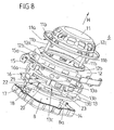
- FIG. 8 shows a modification of the in FIG. 5 shown airbag module 6, in which, in contrast to FIG. 5 the ring 16 is not interrupted by the recess 21 along the direction of movement B.
- the recess 21 of the ring 16 is here formed on the bottom plate 13 facing edge of the ring 16, in such a way that also a transverse to the direction B extending edge 22 of the recess 21 is formed, against which the piston 20 for moving the ring sixteenth can press.
- FIG. 8 illustrated modification of the airbag module 6 of the ring 16 is not as in the FIG.
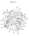
- FIG. 9 shows in connection with FIG. 10 and FIG. 11 another variation of the in the FIG. 5 respectively.
- FIG. 8 shown airbag module 6, in which, in contrast to FIG. 5 respectively.
- FIG. 8 a recess 21 is provided on the ring 16, which does not interrupt the ring 16, ie, the ring 16 is formed closed in itself, so that the piston 20, which presses against the edge 22 of this recess 21 for moving the ring 16, the Ring 16 slides along the direction of movement B. So that the ring 16 is less strongly deformed in this case by the piston 20 when moving relative to the wall 15, it has perpendicular to the direction of movement B a substantially U-shaped cross section or a comparable profiling.
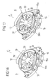
- FIG. 12 shows in connection with FIG. 13 and FIG. 14 an alternative variant of an airbag module 6, in which, in contrast to FIG. 5 .
- FIG. 8 and FIG. 11 the movable element is not formed by a ring 16, but by the gas generator 8 itself Figures 5 . 8th and 11 can be dispensed with a bottom plate 13 here.
- the chamber 9 surrounding the gas generator 8 is formed in this case by at least a first and a second chamber element, namely the generator support 12 as the first chamber element, which lies opposite the trough-shaped support 14 as the second chamber element along the main deployment direction H, at which a central Gasgeneratoraus strictlyung 14a, through which a free end region of the gas generator 8 projects along the main deployment direction H, the gas generator 8 having a gas generator 8 and projecting from the gas generator 8 flange 8a, via which the gas generator 8 is mounted on a gas generator recess 14a peripheral edge region is, along the main deployment direction H of a blowing port 3, not shown, of the airbag module 1 of the airbag module 6 is opposite and facing it.
- the carrier 14 has a circumferential edge region 14c, which faces the generator carrier 12 along the main deployment direction H and can rest against it for forming the chamber 9 surrounding the gas generator 8.
- the cap-shaped diffuser 11 On the central opening 12c of the generator support 12 sits the cap-shaped diffuser 11, wherein as described above, between the diffuser 11 and the generator support 12 of the airbag 1 is clamped with its the inflation opening 3 peripheral edge region. From the diffuser 11 are, as described above, from fastening elements 11b, which are aligned with the fastening elements 11b aligned holes 12b of the generator support 12 and these holes 12b aligned holes 14b of the carrier 14 and with the holes 14b of the carrier 14 aligned slots 24a of a locking element 24 are guided and with along the main deployment direction H longitudinally extending trained nuts 25 are screwed.
- the nuts 25 are formed so that they are inserted in a bolted to the fastening means 11 b along the main deployment direction H in the slots 24 a of the locking element 24 and aligned with the fastening elements 11 b holes 14 b of the support 14, so that the support 14 along the Hauptentfaltungsides H on the nuts 25 along the main deployment direction H can slide. That is, the nuts 25 constitute guide members for the gas generator 8 and the carrier 14 (second chamber member), which can be guided by the guide members 25 through a pressure acting upon inflation of the airbag 1 along a direction of movement B opposite to the main deployment direction H.
- the first outflow opening 15a is closed to fix when inflating the airbag 1, the locking element 24 is provided, which is engageable with the guide elements 25 in engagement, that the gas generator 8 with the Carrier 14 along the direction of movement B can press against the locking element 24 (due to the pressure) and is held in its initial position with respect to the injection port 3, ie, the carrier 14 connected via the flange 8a of the gas generator 8 with the gas generator 8 is located with his the generator support 12 facing edge region 14c on the generator support 12, so that along the main deployment direction H between the carrier 14 and the generator support 12 no Gas or only relatively small amounts of gas from the gas generator 8 surrounding chamber 9 can escape (so it is not necessary that the edge portion 14c of the carrier 14 sealingly abuts the generator support 12).
- the piston 28 of the movement-generating device 26 is arranged with respect to the locking element 24 such that it is displaced linearly along the unlocking direction E by the piston 28.
- the locking element 24 is disengaged from notches 25a of the guide elements 25, so that the gas generator 8 is spaced along the direction of movement B of the injection port 3 of the airbag 1 due to the pressure acting on inflation of the airbag 1.
- the carrier 14, which is connected to the gas generator 8, namely its edge region 14c moves away from the generator carrier 12, so that a gap surrounding the gas generator 8 is formed between the edge region 14c of the carrier 14 and the generator carrier 12, and the first outflow opening 15a forms.
- This position of the gas generator 8 and the carrier 14 is in the FIG. 12 shown.
- shows FIG. 13 shows FIG. 13 the initial position of the gas generator 8 and the carrier 14 with a voltage applied to the generator support 12 edge region 14c of the carrier 14. This corresponds to a sealed first discharge opening 15a.
- FIG. 15 shows a detail of the in the FIGS. 12 to 14 shown airbag module 6, namely the principle according to which the substantially annular locking element 24 which is the carrier 14 along the main deployment direction H opposite, with the guide elements 25 is engageable.
- the locking element 24, the elongated holes 24a which extend along the unlocking E, wherein the slots A widen along the unlocking direction E and accordingly each have a narrow portion 24c, which along the unlocking E expanded one Region 24b of a slot 24a opposite and is divided by a constriction of this flared portion 24b.
- the notches 25a of the guide elements 25 are annular and circulate the guide elements 25 transversely to the direction of movement B.
- the outer diameter of the notches 25a of the guide elements 25 is just so large that the guide elements 25 are pressed with their notches 25a in the narrow portions 24c of the slots 24a and snap through the constrictions between the narrow portions 24c and the flared portions 24b in the narrow portions 24c. In this position, the guide elements 25 can no longer be moved along the direction of movement B.
- the igniter 27 of the movement generating device 26 is ignited and the piston 28 thereby along the unlocking E is pressed against the locking member 24 so that the narrow portions 24c of the elongated holes 24a are pushed out of the notches 25a of the guide members 25 and the expanded portions 24b are displaced toward the guide members 25.
- the locking member 24 is disengaged from the notches 25a of the guide members 25 because the outer diameter of the guide members 25 spaced apart from the notches 25a is smaller than the diameter of the expanded portions 24b of the elongated holes 24a. That is, the locking member 24 can now slide along with the carrier 14 and the gas generator 8 attached thereto along the direction of movement B on the guide elements 25.
- FIG. 16 shows in connection with FIG. 17 and FIG. 18 a perspective, fragmentary view or exploded view of an airbag module 6, the generator support 12, in contrast to the embodiments of the generator support 12 shown above, no permanently open central opening 12c, but a plurality of radially arranged outflow openings 29, through the gas from the chamber 9 of the airbag module 26 can pass through the injection opening 3 in the airbag 1.
- these outflow openings 29 face along the main deployment direction H of the airbag 1 of the injection opening 3 and are opposite this along the main deployment direction H.
- the outflow openings 29 may be formed in such a way that the gas which passes through these outflow openings 29 for inflating the airbag 1, is swirled by the special design of the outflow openings 29, so that the diffuser 11 is dispensable. That is, in the FIGS. 16 to 18 shown airbag module 6 has only a clamping ring 30, on which the generator carrier 12 facing edge region 11a is formed (see FIG. 5 ), which presses an edge portion of the airbag 1 surrounding the inflation opening 3 against the generator support 12 and thus fixes the airbag 1 to the generator support 12.
- clamping ring 30 stand along the main deployment direction H from the fastening elements 11b, according to the embodiments of the airbag module 6 described above.
- valve plate 32 is formed, which has a plurality of openings 32a, which can be brought into coincidence with the outflow openings 29 of the Ausström Symposiumes 31 of the generator carrier 12.
- valve plate 32 together with the attached thereto ring 16 (ring 16 and valve plate 32 may be integrally formed) along a direction transverse to the main deployment direction H extending direction of movement B are rotated, ie, the valve plate 32 may be about an axis perpendicular to the valve plate 32 axis , which coincides with the main deployment direction H, are rotated, wherein the openings 32a of the valve plate 32 can be made to coincide with the outflow openings 29 of the outflow region 31 - the outflow openings 29 are opened - or the outflow openings 29 are completely closable by means of the valve plate 32. Since the valve plate 32 is coupled to the ring 16, the valve plate 32 via the in the FIGS.
- the outflow openings 29 are formed on the outflow region 31 of the generator carrier 12 such that when the outlet openings 29 are closed by the valve plate 32, the first outflow openings 15a of the cylindrical wall 15 of the generator carrier 12 are opened and the outflow openings 15a are closed by the ring 16, if the Outflow openings 29 are opened, that is, with the openings 32 a formed on the valve plate 32 are in coincidence.
- the gas generator 8 may, for example, according to FIG. 14 be formed to be movable along the direction of movement B, wherein additionally the central opening 12c of the generator support 12 through a discharge area 31 with corresponding outflow openings 29 according to the FIG. 18 can be equipped, so that in the FIG. 14 illustrated central opening 12b of the generator carrier 12 by means of a valve plate 32 is closed.
- a respective movement generating device according to the FIG. 7 intended.
Claims (37)
- Module d'airbag pour un véhicule automobile, comportant- un coussin à gaz (1) qui, pour la protection d'un passager, peut être gonflé avec du gaz à travers un orifice d'insufflation (3) du coussin à gaz (1),- un couvercle (7) destiné à recevoir le coussin à gaz (1), qui sépare un espace extérieur (A) du module d'airbag (6) vis-à-vis d'un espace intérieur (I) du module d'airbag (6),- le coussin à gaz (1) pouvant être déployé dans l'espace extérieur (A) du module d'airbag (6) à travers une zone (10) ouvrable du couvercle (7),- un générateur de gaz (8) avec lequel est engendré le gaz destiné à gonfler le coussin à gaz (1), celui-ci sortant hors d'au moins un orifice de sortie de gaz du générateur de gaz (8) et parvenant à travers l'orifice d'insufflation (3) jusque dans le coussin à gaz (1), et- le module d'airbag (6) présentant un premier orifice d'échappement (16a) au niveau d'une chambre (9) entourant le générateur de gaz, chambre à laquelle est associée un élément (8, 14 ; 16) mobile au moins entre deux positions différentes ; par le mouvement de cet élément entre les deux positions le premier orifice d'échappement (15a) peut être relié en conduisant le gaz avec l'orifice de sortie de gaz du générateur de gaz (8), de telle sorte que le gaz s'écoulant à travers l'orifice de sortie de gaz est conduit au moins partiellement dans l'espace extérieur (A),caractérisé en ce que- le coussin à gaz (1) présente un deuxième orifice d'échappement (4) qui, dans un état gonflé du coussin à gaz (1), est agencé dans l'espace intérieur (I) du module d'airbag (6) de telle sorte que du gaz sortant hors du deuxième orifice d'échappement (4) parvient à travers la zone ouvrable (10) du couvercle (7) jusque dans l'espace extérieur (A), et- en ce que le coussin à gaz (1) présente, pour faire échapper du gaz, un troisième orifice d'échappement (5) qui, lorsqu'un coussin à gaz (1) est déployé, est agencé dans l'espace extérieur (A) du module d'airbag (6).
- Module d'airbag selon la revendication 1, caractérisé en ce qu'au moyen de l'élément mobile (8, 14 ; 16), l'orifice de sortie de gaz du générateur de gaz (8) peut être relié en conduisant le gaz avec le premier orifice d'échappement (15a), de telle sorte que le gaz s'écoulant hors de l'orifice d'échappement est conduit entièrement jusque dans l'espace extérieur (A).
- Module d'airbag selon la revendication 1 ou 2, caractérisé en ce que le premier orifice d'échappement (15a) est agencé dans l'espace intérieur (I) du module d'airbag (6) de telle sorte que du gaz sortant hors du premier orifice d'échappement (15a) parvient à travers la zone ouvrable (10) jusque dans l'espace extérieur (A).
- Module d'airbag selon l'une quelconque des revendications précédentes, caractérisé en ce que l'élément mobile (8, 14 ; 16) est monté de telle sorte qu'il est déplaçable dans une direction de mouvement (B) s'étendant parallèlement à une direction principale de déploiement (H) du coussin à gaz (1).
- Module d'airbag selon l'une quelconque des revendications précédentes, caractérisé en ce que l'élément mobile (8, 14 ; 16) est monté de telle sorte qu'il est déplaçable et/ou rotatif dans une direction de mouvement (B) s'étendant parallèlement à l'orifice d'insufflation (3).
- Module d'airbag selon l'une quelconque des revendications précédentes, caractérisé en ce que l'élément mobile entoure le générateur de gaz (8).
- Module d'airbag selon la revendication 4 ou 5, et selon la revendication 6, caractérisé en ce que le générateur de gaz (8) est relié à la chambre (9) de telle sorte que le premier orifice d'échappement (15a) est libéré par un mouvement du générateur de gaz (8) selon la direction de mouvement (B).
- Module d'airbag selon la revendication 7, caractérisé en ce que le générateur de gaz (8) est réalisé de telle sorte que le mouvement du générateur de gaz (8) selon la direction de mouvement (B) a lieu par une pression générée lors de l'écoulement de gaz.
- Module d'airbag selon la revendication 7 ou 8, caractérisé en ce que la chambre (9) est formée à partir d'au moins un premier et un deuxième élément de chambre (12, 14) qui sont montés mobiles l'un par rapport à l'autre selon la direction de mouvement (B).
- Module d'airbag selon la revendication 9, caractérisé en ce que les deux éléments de chambre (12, 14) sont montés mobiles l'un par rapport à l'autre via des éléments de guidage (25) s'étendant en longueur selon la direction de mouvement (B).
- Module d'airbag selon la revendication 9 ou 10, caractérisé en ce que le coussin à gaz (1) est immobilisé sur le premier élément de chambre (12).
- Module d'airbag selon l'une des revendications 9 à 11, caractérisé en ce que le générateur de gaz (8) est relié au deuxième élément de chambre (14).
- Module d'airbag selon l'une des revendications 9 à 12, caractérisé en ce que le générateur de gaz (8) est relié au deuxième élément de chambre (14) de telle sorte que celui-ci est espacé du premier élément de chambre (12) par un mouvement du générateur de gaz (8) selon la direction de mouvement (B) de telle sorte que le premier orifice d'échappement (15a) se forme selon la direction de mouvement (B) entre les deux éléments de chambre (12, 14).
- Module d'airbag selon l'une quelconque des revendications précédentes, caractérisé par un élément de verrouillage (24) détachable destiné à immobiliser le générateur de gaz (8).
- Module d'airbag selon les revendications 10 et 14, caractérisé en ce que l'élément de verrouillage (24) est réalisé de telle sorte qu'il peut être mis en engagement avec les éléments de guidage (25) pour immobiliser le générateur de gaz (8).
- Module d'airbag selon la revendication 14 et selon l'une des revendications 11 à 13, prises en dépendance de la revendication 10, caractérisé en ce que l'élément de verrouillage (24) est réalisé de telle sorte qu'il peut être mis en engagement avec les éléments de guidage (25) pour immobiliser le générateur de gaz (8).
- Module d'airbag selon la revendication 4 ou 5 et selon la revendication 15, caractérisé en ce que l'élément de verrouillage (24) peut être amené au moins partiellement hors d'engagement avec les éléments de guidage (25) par un mouvement linéaire selon une direction de déverrouillage (E) s'étendant transversalement à la direction de mouvement (B).
- Module d'airbag selon la revendication 17, caractérisé en ce que l'élément de verrouillage (24) présente des trous oblongs (24a) s'étendant en longueur selon la direction de déverrouillage (E), dans lesquels les éléments de guidage (25) s'engagent pour immobiliser le générateur de gaz (8).
- Module d'airbag selon la revendication 17 ou 18, caractérisé par un dispositif de génération de mouvement (26) pour générer le mouvement linéaire de l'élément de verrouillage (24).
- Module d'airbag selon la revendication 19, caractérisé en ce que le dispositif de génération de mouvement (26) présente un piston (28) qui presse contre l'élément de verrouillage (24) pour détacher l'élément de verrouillage (24) selon la direction de déverrouillage (E).
- Module d'airbag selon l'une des revendications 1 à 5, caractérisé en ce que l'élément mobile est monté mobile dans la chambre (9) de telle sorte que le premier orifice d'échappement (15a) peut être fermé par l'élément mobile.
- Module d'airbag selon la revendication 21, caractérisé en ce que la chambre (9) présente une paroi (15) cylindrique dans laquelle est agencé le premier orifice d'échappement (15a).
- Module d'airbag selon la revendication 22, caractérisé en ce que l'élément mobile présente une bague cylindrique (16) avec une échancrure (16a), la bague (16) étant agencée de façon à pouvoir se déplacer sur la paroi (15) de la chambre (9) de telle sorte que l'échancrure (16a) peut être amenée en recouvrement avec le premier orifice d'échappement (15a) par un déplacement de la bague (16) le long de la paroi (15).
- Module d'airbag selon la revendication 23, caractérisé en ce que la bague (16) présente un évidement (21) avec un bord (22) orienté transversalement à la direction de mouvement (B) pour déplacer la bague (16) selon la direction de mouvement (B).
- Module d'airbag selon la revendication 24, caractérisé en ce que l'évidement (21) est réalisé sous forme d'une fente interrompant la bague (16), laquelle s'étend transversalement à la direction de mouvement (B).
- Module d'airbag selon la revendication 24, caractérisé en ce qu'un autre évidement (23) s'étend le long du bord (22) de l'évidement (21), sous la forme d'une fente interrompant la bague (16).
- Module d'airbag selon l'une des revendications 20 à 25, caractérisé en ce que l'élément mobile (16) est mobile au moyen d'un dispositif de génération de mouvement (17).
- Module d'airbag selon la revendication 26, caractérisé en ce que le dispositif de génération de mouvement (17) présente un piston (20) qui presse contre le bord (22) de l'évidement (21) pour déplacer la bague (16) selon la direction de mouvement (B).
- Module d'airbag selon l'une des revendications 21 à 28, caractérisé en ce que la chambre (9) présente un orifice d'écoulement (29) qui peut être fermé, à travers lequel du gaz peut parvenir dans le coussin à gaz (1) pour gonfler le coussin à gaz (1).
- Module d'airbag selon la revendication 29, caractérisé en ce que l'orifice d'écoulement (29) est agencé dans une zone d'écoulement (31) tournée vers le coussin à gaz (1), de la chambre (9).
- Module d'airbag selon l'une des revendications 21 à 30, caractérisé en ce que l'élément mobile présente une plaque de soupape (32) avec une ouverture (32a), la plaque de soupape (32) est agencée déplaçable sur la zone d'écoulement (31) de la chambre (9), de telle sorte que l'ouverture (32a) peut être amenée en recouvrement avec l'orifice d'écoulement (29) par un déplacement de la plaque de soupape (32) le long de la zone d'écoulement (31).
- Module d'airbag selon l'une des revendications 23 à 28 et selon la revendication 31, caractérisé en ce que la plaque de soupape (32) est immobilisée sur un bord périphérique de la bague (16), qui est tourné du coussin à gaz (1).
- Module d'airbag selon la revendication 32, caractérisé en ce que l'ouverture (32a) de la plaque de soupape (32) est agencée par rapport à l'échancrure (16a) de la bague (16) de telle sorte que l'orifice d'écoulement (29) est fermé par la plaque de soupape (32) lorsque le premier orifice d'échappement (15a) est ouvert, et en ce que l'orifice d'écoulement (29) est ouvert lorsque le premier orifice d'échappement (15a) est fermé par la bague (16).
- Module d'airbag selon l'une quelconque des revendications précédentes, caractérisé en ce qu'il est prévu des moyens qui empêchent en grande partie que le gaz sortant hors du premier et du deuxième orifice d'échappement (15a, 4) puisse parvenir dans une direction orientée en sens opposé à la direction principale de déploiement (H).
- Module d'airbag selon l'une quelconque des revendications précédentes, caractérisé en ce que le troisième orifice d'échappement (5) est agencé, à l'état gonflé du coussin à gaz (1), sur un côté (2) du coussin à gaz (1) tourné vers le module d'airbag (6).
- Module d'airbag selon l'une des revendications 1 à 34 ou selon la revendication 35, caractérisé en ce que pour faire échapper du gaz, le coussin à gaz (1) présente un autre troisième orifice d'échappement (5) qui, dans le cas d'un coussin à gaz (1) déployé, est agencé dans l'espace extérieur (A) du module d'airbag (6).
- Module d'airbag selon l'une des revendications 1 à 34 ou la revendication 35 et selon la revendication 36, caractérisé en ce que dans l'état gonflé du coussin à gaz (1), l'autre troisième orifice d'échappement (5) est opposé au troisième orifice d'échappement (5) transversalement à la direction principale de déploiement (H) du coussin à gaz (1).
Applications Claiming Priority (3)
| Application Number | Priority Date | Filing Date | Title |
|---|---|---|---|
| DE102005027910 | 2005-06-10 | ||
| DE202005020680U DE202005020680U1 (de) | 2005-06-10 | 2005-12-15 | Airbagmodul |
| PCT/DE2006/001005 WO2006131111A1 (fr) | 2005-06-10 | 2006-06-07 | Module de coussin gonflable de securite |
Publications (2)
| Publication Number | Publication Date |
|---|---|
| EP1890915A1 EP1890915A1 (fr) | 2008-02-27 |
| EP1890915B1 true EP1890915B1 (fr) | 2008-10-08 |
Family
ID=36972690
Family Applications (1)
| Application Number | Title | Priority Date | Filing Date |
|---|---|---|---|
| EP06742409A Expired - Fee Related EP1890915B1 (fr) | 2005-06-10 | 2006-06-07 | Module de coussin gonflable de securite |
Country Status (5)
| Country | Link |
|---|---|
| US (1) | US7513527B2 (fr) |
| EP (1) | EP1890915B1 (fr) |
| JP (1) | JP4568784B2 (fr) |
| DE (2) | DE502006001778D1 (fr) |
| WO (1) | WO2006131111A1 (fr) |
Families Citing this family (5)
| Publication number | Priority date | Publication date | Assignee | Title |
|---|---|---|---|---|
| DE112007000706A5 (de) * | 2006-03-30 | 2008-12-24 | Takata-Petri Ag | Airbagmodul für ein Kraftfahrzeug |
| JP5186832B2 (ja) | 2007-08-09 | 2013-04-24 | タカタ株式会社 | エアバッグ及びエアバッグ装置 |
| US7806434B2 (en) * | 2007-10-29 | 2010-10-05 | Autoliv Asp, Inc. | Adaptive airbag gas flow apparatus |
| US7823920B1 (en) * | 2009-06-16 | 2010-11-02 | Trw Vehicle Safety Systems Inc. | Inflatable vehicle occupant protection device with inflation fluid deflector |
| JP5432011B2 (ja) * | 2010-03-12 | 2014-03-05 | 芦森工業株式会社 | エアバッグ装置の取付部構造 |
Family Cites Families (41)
| Publication number | Priority date | Publication date | Assignee | Title |
|---|---|---|---|---|
| JPH0350566U (fr) * | 1989-09-25 | 1991-05-16 | ||
| US5234229A (en) * | 1992-02-25 | 1993-08-10 | General Motors Corporation | Pressure limited restraint system |
| JPH0640305A (ja) * | 1992-07-23 | 1994-02-15 | Toyota Motor Corp | エアバッグの圧力調整装置 |
| JPH06305392A (ja) * | 1993-04-27 | 1994-11-01 | Toyota Motor Corp | サイドエアバッグ装置のガス排出構造 |
| JPH09142241A (ja) * | 1995-11-24 | 1997-06-03 | Honda Motor Co Ltd | 乗員保護用エアバッグ装置 |
| US5709405A (en) * | 1996-04-10 | 1998-01-20 | Morton International, Inc. | Variable mass flow airbag module |
| KR100192427B1 (ko) | 1996-12-19 | 1999-06-15 | 정몽규 | 인플레이터 일체식 가변형 에어백의 벤트홀 |
| US6039346A (en) * | 1997-01-17 | 2000-03-21 | General Motors Corporation | Air bag module with variable inflation |
| JP3427877B2 (ja) * | 1997-04-01 | 2003-07-22 | トヨタ自動車株式会社 | エアバッグ装置 |
| DE19809573B4 (de) | 1998-03-05 | 2006-03-16 | Delphi Automotive Systems Deutschland Gmbh | Luftsackmodul |
| DE19810537A1 (de) * | 1998-03-11 | 1999-09-16 | Trw Airbag Sys Gmbh & Co Kg | Verfahren zum Steuern eines Fahrzeuginsassen-Rückhaltesystems und Fahrzeuginsassen-Rückhaltesystem |
| JP3788033B2 (ja) | 1998-05-29 | 2006-06-21 | タカタ株式会社 | エアバッグ装置 |
| JP3694727B2 (ja) | 1998-07-27 | 2005-09-14 | 日産自動車株式会社 | 自動車用安全装置 |
| US6669231B2 (en) * | 1998-11-04 | 2003-12-30 | Delphi Technologies, Inc. | Adaptive venting for an air bag module |
| US6213502B1 (en) * | 1998-11-24 | 2001-04-10 | Delphi Technologies, Inc. | Air bag module with variable inflation |
| US6206408B1 (en) * | 1999-01-25 | 2001-03-27 | Autoliv Asp, Inc. | Air bag module emergency venting system |
| JP2000313303A (ja) * | 1999-04-28 | 2000-11-14 | Nippon Plast Co Ltd | エアバッグ及びエアバッグ装置 |
| JP3239118B2 (ja) * | 1999-09-30 | 2001-12-17 | 日本プラスト株式会社 | エアバッグ及びエアバッグ装置 |
| US6439603B2 (en) * | 1999-10-13 | 2002-08-27 | Delphi Technologies, Inc. | Air bag module with variable inflation |
| JP4394792B2 (ja) * | 1999-11-22 | 2010-01-06 | 本田技研工業株式会社 | エアバッグ装置 |
| JP4394793B2 (ja) * | 2000-02-07 | 2010-01-06 | 本田技研工業株式会社 | エアバッグ装置 |
| JP2001219804A (ja) * | 2000-02-09 | 2001-08-14 | Honda Motor Co Ltd | エアバッグ装置 |
| AU2001279763A1 (en) * | 2000-07-25 | 2002-02-05 | Volkswagen Aktiengesellschaft | Occupant protection device |
| US6406055B1 (en) * | 2001-02-13 | 2002-06-18 | Trw Vehicle Safety Systems Inc. | Air bag module with vent |
| DE10124273A1 (de) | 2001-05-18 | 2002-11-21 | Daimler Chrysler Ag | Rückhaltesystem |
| US6692022B2 (en) * | 2001-07-14 | 2004-02-17 | Delphi Technologies, Inc. | Active venting of an airbag module |
| JP4759867B2 (ja) | 2001-07-25 | 2011-08-31 | タカタ株式会社 | エアバッグ装置 |
| DE10139626A1 (de) * | 2001-08-14 | 2003-03-13 | Takata Petri Ag | Airbaganordnung |
| DE10146383A1 (de) * | 2001-09-20 | 2003-04-30 | Trw Repa Gmbh | Verfahren zur Steuerung der Gaserzeugung in einem Gassackmoduls |
| US7108277B2 (en) * | 2001-10-12 | 2006-09-19 | Trw Vehicle Safety Systems Inc. | Air bag module with vent cover |
| US20030107207A1 (en) * | 2001-10-12 | 2003-06-12 | Trw Inc. | Air bag module with vent cover |
| US6736425B2 (en) * | 2002-01-28 | 2004-05-18 | Ford Global Technologies, Llc | System for venting an air bag module |
| GB2389342A (en) * | 2002-06-05 | 2003-12-10 | Autoliv Dev | Air-bag with vent opened by pivoting gas generator |
| JP4334853B2 (ja) * | 2002-06-28 | 2009-09-30 | ダイセル化学工業株式会社 | エアバッグ装置 |
| US20040135356A1 (en) * | 2002-06-28 | 2004-07-15 | Nobuyuki Katsuda | Air bag apparatus |
| JP3982423B2 (ja) * | 2003-01-30 | 2007-09-26 | 豊田合成株式会社 | エアバッグ |
| JP4122039B2 (ja) * | 2003-04-16 | 2008-07-23 | キー セーフティー システムズ、 インコーポレイテッド | 膨張ガスの排気を制御されたエアバッグモジュール |
| DE10361887A1 (de) * | 2003-12-19 | 2005-07-14 | Takata-Petri Ag | Airbageinrichtung für ein Kraftfahrzeug |
| GB2413781B (en) * | 2004-05-05 | 2007-03-14 | Autoliv Dev | Improvements in or relating to an air-bag arrangement |
| JP4396492B2 (ja) * | 2004-11-26 | 2010-01-13 | 豊田合成株式会社 | ステアリングホイール用エアバッグ装置 |
| EP1995127A3 (fr) * | 2005-06-10 | 2009-04-08 | Takata-Petri AG | Module d'airbag |
-
2006
- 2006-06-07 WO PCT/DE2006/001005 patent/WO2006131111A1/fr active Application Filing
- 2006-06-07 DE DE502006001778T patent/DE502006001778D1/de active Active
- 2006-06-07 JP JP2008515045A patent/JP4568784B2/ja not_active Expired - Fee Related
- 2006-06-07 DE DE112006002120T patent/DE112006002120A5/de not_active Withdrawn
- 2006-06-07 EP EP06742409A patent/EP1890915B1/fr not_active Expired - Fee Related
-
2007
- 2007-12-10 US US12/000,195 patent/US7513527B2/en not_active Expired - Fee Related
Also Published As
| Publication number | Publication date |
|---|---|
| JP4568784B2 (ja) | 2010-10-27 |
| DE112006002120A5 (de) | 2008-05-21 |
| US7513527B2 (en) | 2009-04-07 |
| EP1890915A1 (fr) | 2008-02-27 |
| JP2008542115A (ja) | 2008-11-27 |
| WO2006131111A1 (fr) | 2006-12-14 |
| US20080150264A1 (en) | 2008-06-26 |
| DE502006001778D1 (de) | 2008-11-20 |
Similar Documents
| Publication | Publication Date | Title |
|---|---|---|
| DE10210328B4 (de) | Luftsacksystem für Kraftfahrzeuge | |
| EP1231116B1 (fr) | Module de sac gonflable | |
| DE19749914A1 (de) | Vorrichtung für einen Aufprallschutz am Lenkrad eines Kraftfahrzeugs | |
| DE102010003024A1 (de) | Ein Mehrkammerairbagsystem | |
| EP1288084B1 (fr) | Module de coussin gonflable | |
| DE102009023961A1 (de) | Aktuator mit Auslösebolzen | |
| EP0932526B1 (fr) | Procede pour assurer la securite d'un passager dans un vehicule et module airbag pour la mise en oeuvre de ce procede | |
| EP1155924A2 (fr) | Module de sac de sécurité gonflable | |
| EP1890915B1 (fr) | Module de coussin gonflable de securite | |
| EP1412232B1 (fr) | Systeme de retenue des passagers dans la zone des sieges arriere d'un vehicule automobile | |
| DE10020929C5 (de) | Airbagmodul | |
| EP1270342B1 (fr) | Module de coussin gonflable | |
| EP1238866B1 (fr) | Module de coussin gonflable | |
| EP1467898A1 (fr) | Module de coussin gonflable de securite destine a des vehicules | |
| DE10039800B4 (de) | Fahrzeugdach, insbesondere für ein Kraftfahrzeug | |
| DE19951029A1 (de) | Airbageinrichtung an einem Lenkrad eines Fahrzeugs | |
| EP1891312B1 (fr) | Module de coussin gonflable de securite | |
| EP1893521B1 (fr) | Module airbag pour un vehicule automobile | |
| EP1131229B1 (fr) | Systeme de coussin gonflable situe sur le volant d'un vehicule | |
| EP1527963B1 (fr) | Module de coussin gonflable | |
| DE102005060685A1 (de) | Airbagmodul | |
| DE102005060684A1 (de) | Airbagmodul | |
| DE202005020687U1 (de) | Airbagmodul | |
| DE202005020680U1 (de) | Airbagmodul | |
| DE10065461C2 (de) | Beifahrerairbagmodul |
Legal Events
| Date | Code | Title | Description |
|---|---|---|---|
| PUAI | Public reference made under article 153(3) epc to a published international application that has entered the european phase |
Free format text: ORIGINAL CODE: 0009012 |
|
| 17P | Request for examination filed |
Effective date: 20080108 |
|
| AK | Designated contracting states |
Kind code of ref document: A1 Designated state(s): DE FR GB SE |
|
| DAX | Request for extension of the european patent (deleted) | ||
| GRAP | Despatch of communication of intention to grant a patent |
Free format text: ORIGINAL CODE: EPIDOSNIGR1 |
|
| RIN1 | Information on inventor provided before grant (corrected) |
Inventor name: LUBE, THOMAS Inventor name: HOFMANN, HEIKO Inventor name: MEISSNER, DIRK Inventor name: WINKLER, ANDREAS |
|
| RBV | Designated contracting states (corrected) |
Designated state(s): DE FR GB SE |
|
| GRAS | Grant fee paid |
Free format text: ORIGINAL CODE: EPIDOSNIGR3 |
|
| GRAA | (expected) grant |
Free format text: ORIGINAL CODE: 0009210 |
|
| DAX | Request for extension of the european patent (deleted) | ||
| AK | Designated contracting states |
Kind code of ref document: B1 Designated state(s): DE FR GB SE |
|
| REG | Reference to a national code |
Ref country code: GB Ref legal event code: FG4D Free format text: NOT ENGLISH |
|
| REF | Corresponds to: |
Ref document number: 502006001778 Country of ref document: DE Date of ref document: 20081120 Kind code of ref document: P |
|
| PLBE | No opposition filed within time limit |
Free format text: ORIGINAL CODE: 0009261 |
|
| STAA | Information on the status of an ep patent application or granted ep patent |
Free format text: STATUS: NO OPPOSITION FILED WITHIN TIME LIMIT |
|
| PG25 | Lapsed in a contracting state [announced via postgrant information from national office to epo] |
Ref country code: SE Free format text: LAPSE BECAUSE OF FAILURE TO SUBMIT A TRANSLATION OF THE DESCRIPTION OR TO PAY THE FEE WITHIN THE PRESCRIBED TIME-LIMIT Effective date: 20090108 |
|
| 26N | No opposition filed |
Effective date: 20090709 |
|
| GBPC | Gb: european patent ceased through non-payment of renewal fee |
Effective date: 20100607 |
|
| PG25 | Lapsed in a contracting state [announced via postgrant information from national office to epo] |
Ref country code: GB Free format text: LAPSE BECAUSE OF NON-PAYMENT OF DUE FEES Effective date: 20100607 |
|
| PGFP | Annual fee paid to national office [announced via postgrant information from national office to epo] |
Ref country code: DE Payment date: 20120530 Year of fee payment: 7 |
|
| PGFP | Annual fee paid to national office [announced via postgrant information from national office to epo] |
Ref country code: FR Payment date: 20120619 Year of fee payment: 7 |
|
| REG | Reference to a national code |
Ref country code: DE Ref legal event code: R082 Ref document number: 502006001778 Country of ref document: DE Representative=s name: MAIKOWSKI & NINNEMANN PATENTANWAELTE, DE |
|
| REG | Reference to a national code |
Ref country code: DE Ref legal event code: R082 Ref document number: 502006001778 Country of ref document: DE Representative=s name: MAIKOWSKI & NINNEMANN PATENTANWAELTE, DE Effective date: 20120904 Ref country code: DE Ref legal event code: R081 Ref document number: 502006001778 Country of ref document: DE Owner name: TAKATA AKTIENGESELLSCHAFT, DE Free format text: FORMER OWNER: TAKATA-PETRI AG, 63743 ASCHAFFENBURG, DE Effective date: 20120904 |
|
| REG | Reference to a national code |
Ref country code: DE Ref legal event code: R119 Ref document number: 502006001778 Country of ref document: DE Effective date: 20140101 |
|
| REG | Reference to a national code |
Ref country code: FR Ref legal event code: ST Effective date: 20140228 |
|
| PG25 | Lapsed in a contracting state [announced via postgrant information from national office to epo] |
Ref country code: DE Free format text: LAPSE BECAUSE OF NON-PAYMENT OF DUE FEES Effective date: 20140101 |
|
| PG25 | Lapsed in a contracting state [announced via postgrant information from national office to epo] |
Ref country code: FR Free format text: LAPSE BECAUSE OF NON-PAYMENT OF DUE FEES Effective date: 20130701 |