EP1890915B1 - Airbag module - Google Patents
Airbag module Download PDFInfo
- Publication number
- EP1890915B1 EP1890915B1 EP06742409A EP06742409A EP1890915B1 EP 1890915 B1 EP1890915 B1 EP 1890915B1 EP 06742409 A EP06742409 A EP 06742409A EP 06742409 A EP06742409 A EP 06742409A EP 1890915 B1 EP1890915 B1 EP 1890915B1
- Authority
- EP
- European Patent Office
- Prior art keywords
- airbag module
- airbag
- module according
- gas
- orifice
- Prior art date
- Legal status (The legal status is an assumption and is not a legal conclusion. Google has not performed a legal analysis and makes no representation as to the accuracy of the status listed.)
- Expired - Fee Related
Links
- 238000002347 injection Methods 0.000 claims description 19
- 239000007924 injection Substances 0.000 claims description 19
- 238000006073 displacement reaction Methods 0.000 claims description 6
- 239000007789 gas Substances 0.000 description 158
- 230000002093 peripheral effect Effects 0.000 description 6
- 238000012986 modification Methods 0.000 description 4
- 230000004048 modification Effects 0.000 description 4
- 230000014759 maintenance of location Effects 0.000 description 3
- 208000027418 Wounds and injury Diseases 0.000 description 2
- 230000006978 adaptation Effects 0.000 description 2
- 230000006378 damage Effects 0.000 description 2
- 238000013461 design Methods 0.000 description 2
- 208000014674 injury Diseases 0.000 description 2
- 230000001133 acceleration Effects 0.000 description 1
- 230000000712 assembly Effects 0.000 description 1
- 238000000429 assembly Methods 0.000 description 1
- 238000007664 blowing Methods 0.000 description 1
- 238000013016 damping Methods 0.000 description 1
- 230000001419 dependent effect Effects 0.000 description 1
- 238000001514 detection method Methods 0.000 description 1
- 238000007599 discharging Methods 0.000 description 1
- 238000005516 engineering process Methods 0.000 description 1
- 230000001771 impaired effect Effects 0.000 description 1
- 239000000463 material Substances 0.000 description 1
- 230000000452 restraining effect Effects 0.000 description 1
- 238000000926 separation method Methods 0.000 description 1
- 238000012360 testing method Methods 0.000 description 1
- 230000036962 time dependent Effects 0.000 description 1
- 238000013519 translation Methods 0.000 description 1
- 238000009423 ventilation Methods 0.000 description 1
- 238000013022 venting Methods 0.000 description 1
Images


Classifications
-
- B—PERFORMING OPERATIONS; TRANSPORTING
- B60—VEHICLES IN GENERAL
- B60R—VEHICLES, VEHICLE FITTINGS, OR VEHICLE PARTS, NOT OTHERWISE PROVIDED FOR
- B60R21/00—Arrangements or fittings on vehicles for protecting or preventing injuries to occupants or pedestrians in case of accidents or other traffic risks
- B60R21/02—Occupant safety arrangements or fittings, e.g. crash pads
- B60R21/16—Inflatable occupant restraints or confinements designed to inflate upon impact or impending impact, e.g. air bags
- B60R21/26—Inflatable occupant restraints or confinements designed to inflate upon impact or impending impact, e.g. air bags characterised by the inflation fluid source or means to control inflation fluid flow
- B60R21/276—Inflatable occupant restraints or confinements designed to inflate upon impact or impending impact, e.g. air bags characterised by the inflation fluid source or means to control inflation fluid flow with means to vent the inflation fluid source, e.g. in case of overpressure
-
- B—PERFORMING OPERATIONS; TRANSPORTING
- B60—VEHICLES IN GENERAL
- B60R—VEHICLES, VEHICLE FITTINGS, OR VEHICLE PARTS, NOT OTHERWISE PROVIDED FOR
- B60R21/00—Arrangements or fittings on vehicles for protecting or preventing injuries to occupants or pedestrians in case of accidents or other traffic risks
- B60R21/02—Occupant safety arrangements or fittings, e.g. crash pads
- B60R21/16—Inflatable occupant restraints or confinements designed to inflate upon impact or impending impact, e.g. air bags
- B60R21/23—Inflatable members
- B60R21/239—Inflatable members characterised by their venting means
-
- B—PERFORMING OPERATIONS; TRANSPORTING
- B60—VEHICLES IN GENERAL
- B60R—VEHICLES, VEHICLE FITTINGS, OR VEHICLE PARTS, NOT OTHERWISE PROVIDED FOR
- B60R21/00—Arrangements or fittings on vehicles for protecting or preventing injuries to occupants or pedestrians in case of accidents or other traffic risks
- B60R21/02—Occupant safety arrangements or fittings, e.g. crash pads
- B60R21/16—Inflatable occupant restraints or confinements designed to inflate upon impact or impending impact, e.g. air bags
- B60R21/26—Inflatable occupant restraints or confinements designed to inflate upon impact or impending impact, e.g. air bags characterised by the inflation fluid source or means to control inflation fluid flow
- B60R21/276—Inflatable occupant restraints or confinements designed to inflate upon impact or impending impact, e.g. air bags characterised by the inflation fluid source or means to control inflation fluid flow with means to vent the inflation fluid source, e.g. in case of overpressure
- B60R2021/2765—Inflatable occupant restraints or confinements designed to inflate upon impact or impending impact, e.g. air bags characterised by the inflation fluid source or means to control inflation fluid flow with means to vent the inflation fluid source, e.g. in case of overpressure comprising means to control the venting
Definitions
- the invention relates to an airbag module for a motor vehicle according to the preamble of claim 1.
- the document DE 101 39 626 A1 Shows this Gattunssnduenden state of technology
- the invention has for its object to improve the inflation of an airbag module of the type mentioned.
- the airbag module has a first outflow opening, which is associated with at least one movable element between two positions by the movement between the two positions, the first outflow opening is gas-conductively connected to the gas outlet opening of the gas generator such that the gas flowing out through the gas outlet opening at least partially is directed to the outside space.
- a gas quantity with which the gas bag is filled can be adapted to the respective accident situation.
- an oop situation for example, ie, a person to be protected by the gas bag is eg along a main deployment direction of the gas bag is not sufficiently removed from the gas bag, thus early the first discharge opening can be opened so that the person to be protected is not injured by a too inflated airbag.
- the gas outlet opening of the gas generator can be connected in a gas-conducting manner to the first outflow opening such that the gas flowing out through the gas outlet opening is conducted completely into the outer space surrounding the airbag module.
- inflation of the gas bag for example, in the case of an oop situation can be completely prevented.
- the invention provides for a cover of the airbag module, which covers the airbag and separates an interior of the airbag module from an outer space surrounding the airbag module.
- a cover may be, for example, a cover of a hub body of the steering wheel.
- the cover has an openable area through which the gas bag can be deployed into the exterior space of the airbag module.
- the openable area may have tear lines along which the openable area of the cover ruptures due to the deploying gas bag pressing against the cover when inflated along a main deployment direction.
- the second outflow opening is arranged in the interior of the airbag module such that the gas passes through the openable area into the exterior space.
- a risk of injury to a person does not exist here, since the openable area is covered by the unfolding gas bag.
- the movable element is mounted in the airbag module such that it is displaceable in a direction of movement parallel to the main deployment direction of the airbag.
- the movable element is preferably mounted such that it is displaceable and / or rotatable in a direction of movement extending parallel to the injection opening.
- the airbag module has a chamber which surrounds the gas generator of the airbag module.
- the chamber serves to protect the gas bag and, on the other hand, has openable (closable) outflow openings (for introducing gas into the exterior space) or outflow opening (for introducing gas into the gas bag) or can form such outflow openings by movements of components of the chamber.
- the movable element is formed at least by the gas generator, wherein preferably the gas generator is fixed to the chamber such that the first outflow opening is opened by a movement of the gas generator along the direction of movement.
- the gas generator is designed such that the movement of the gas generator along the direction of movement is effected by a pressure generated during the outflow of the gas.
- the chamber surrounding the gas generator is formed at least by a first and a second chamber member, wherein one of the two chamber elements is connected to the gas generator, and wherein the two chamber elements form a receptacle for the gas generator and are movably mounted to each other along the direction of movement, so that They can be moved away from each other along the direction of movement of the gas generator, whereby the first Outflow opening, for example, in the form of a gap surrounding the gas generator to the chamber, that is, between two mutually along the direction of movement facing circumferential edges of the two chamber elements is formed.
- the two chamber elements are preferably mounted so as to be movable relative to one another via guide elements extending along the direction of movement.
- guide elements may for example be integrally connected to one of the two chamber elements and protrude along the direction of movement of this chamber element or another component of the chamber.
- the other chamber member may then have recesses (e.g., through holes) into which these guide members engage so that this other chamber member is movably supported along the direction of travel on the guide members, i.e., the guide members slide through the recesses.
- the gas bag is fixed to the first chamber element, while the gas generator is fixed to the second chamber element.
- the first chamber element, to which the gas bag is attached is arranged along the main deployment direction of the gas bag between the second chamber element and a driver to be protected by the gas bag.
- the gas generator is attached to the second chamber member, that this is spaced by movement of the gas generator along the direction of movement of the gas generator from the first chamber element, wherein along the direction of movement between the two chamber elements, the first outflow opening, for example in the form of a gas generator across to the movement direction circumferential gap forms. That is, the first outflow opening is opened by this movement apart of the two chamber elements.
- a releasable locking element which serves for fixing the gas generator.
- This can fix the gas generator in its initial position when inflating the airbag and can be controlled by control electronics, so that depending on a specific accident situation at a certain time unlocking of the locking element can be done.
- the gas generator which arises due to the gas flowing out Pressure against the locking member, after releasing or unlocking the locking member, following the pressure, moves along the direction of travel away from the inflation opening of the airbag to a further position spaced along the direction of travel from the initial position.
- the locking element is designed such that it can be brought into engagement with the guide elements for securing the gas generator (the locking element can, for example, engage in a form-fitting manner on the guide elements).
- the locking element is configured and provided to be brought at least partially out of engagement with the guide elements by a linear movement along a transverse to the direction of movement of the gas generator unlocking.
- the locking element in this case along the unlocking longitudinally extended, the unlocking along the direction of movement piercing slots on which engage the guide elements to set the generator.
- these elongated holes can widen along the unlocking direction, wherein the guide elements along the direction of movement in expanded portions of these slots are insertable and have notches, in which the locking element, with edge regions that bound the slots at their respective narrow areas, so intervene in that the guide elements press against these edge regions along the direction of movement and are therefore fixed along the direction of movement.
- a narrow and an expanded region of an oblong hole opposite the direction of unlocking can be separated from one another by a constriction or narrowing of the oblong hole transversely to the unlocking direction.
- This is advantageous, since in this way a guide element with its annular circumferential notch can be pressed into the narrow region and is held there by the constriction. Moving a guide element located in a narrow area along the unlocking direction into a widened region of a slot thus presupposes a predefinable minimum force and thus reduces the risk of unintentional unlocking of the locking element.
- a movement generating device which generates the linear movement of the locking element for releasing the locking element.
- this movement-generating device preferably has a piston which presses against the locking element along the unlocking direction, wherein the guide elements are displaced from the narrow areas of the elongated holes into the widened areas of these elongated holes so that they extend transversely to the unlocking direction, i. h., Can slide along the direction of movement in the slots.
- At the locking elements can be formed along the direction of travel broadening, so that the locking element when sliding along the guide elements not completely disengaged from the guide elements. Thus, there is a maximum possible distance between the two chamber elements along the direction of movement.
- the first outflow opening or a plurality of such first outflow openings is formed on a chamber surrounding the gas generator, the gas generator having a fixed position with respect to the injection opening (with the exception of compensating movements which are possible by means of a vibratory mounting of the gas generator).
- the movable element is mounted so movably on this chamber, that the first outflow opening by means of the movable element can be closed or opened.
- the chamber of the gas generator has a cylindrical wall in which the first outflow opening is arranged.
- this cylindrical wall can rotate the gas generator transversely to the main deployment direction of the gas bag of the airbag module.
- the gas outlet opening of the gas generator (or a plurality of such gas outlet openings) of the first outflow opening (or a corresponding plurality of such first outflow openings) transverse to the main deployment direction of the airbag, so that the gas initially flow out transversely to the main deployment direction from the chamber surrounding the gas generator can.
- the movable member has a cylindrical ring with a recess, the ring being displaceable on the wall of the chamber is mounted, that the recess by a displacement of the ring along the wall with the first outflow opening can be brought into coincidence.
- the recess of the ring may have the shape and size of the first outflow opening.
- the cylindrical ring has a corresponding plurality of recesses, which can be brought into coincidence by a displacement of the ring along the wall with these first outflow openings.
- the recess (or recesses) of the ring are formed on the ring so that the ring is rotatable with respect to the wall of the chamber to a position in which the ring completely closes the first outflow opening (or the plurality of first outflow openings) , Likewise, the recesses may be arranged on the ring, that in a certain position of the ring with respect to the wall, all first outflow openings of the wall are open.
- the ring for moving the ring along the direction of movement has a recess with an edge extending transversely to the direction of movement (in a cylindrical wall, the direction of movement preferably rotates the cylindrical wall transversely to the main deployment direction of the airbag, i.e. transverse to the cylindrical axis of the cylindrical wall).
- this recess is formed as a gap interrupting the ring (open ring), which extends transversely to the direction of movement.
- a piston of a movement generating device pushes along the direction of movement against the edge of the recess, so that the ring is pushed by the piston from an initial position in which the first outflow opening is closed by the ring in a further position in which the first outflow opening is open.
- This advantageous tangential force introduction of the ring is only slightly deformed.
- the recess may be formed only partially on the ring, that is, not completely cut through the ring perpendicular to the direction of movement. In this case further preferred is a narrow, the ring Transversely to the direction of separation by further cutting provided, which is formed in the direction of movement behind the edge of the recess and along this edge, ie, transverse to the direction of movement extends.
- the recess of the ring which can be brought to cover the first outflow opening with the first outflow opening in cover, fail due to the minimization of the deformation of the ring particularly large area.
- the recess (or the recesses) may therefore occupy about half of the wall of the chamber facing surface of the ring.
- the chamber surrounding the gas generator has a closable discharge opening through which gas generated or released by the gas generator can flow into the gas bag for inflating the gas bag.
- the outflow opening (this can also be a plurality of outflow openings) is arranged on a discharge area of the chamber facing the injection opening of the airbag.
- the movable element of the airbag module has a valve plate with an opening, wherein the valve plate is movably mounted on the wall of the chamber such that the opening can be brought into coincidence with the outflow opening by displacing (rotating) the valve plate along the outflow region.
- a corresponding plurality of openings is provided on the valve plate, which can be brought into coincidence with the outflow openings by displacement or rotation of the valve plate, whereby the outflow openings of the chamber can be opened.
- the opening or the openings are formed on the valve plate, that the valve plate by turning the valve plate with respect to the outflow area closes all outflow openings of the discharge area of the chamber by a predeterminable angle.
- valve plate is fixed to a peripheral, the airbag or the inflation opening of the airbag facing edge of the ring. That is, the movable member may be formed as a flat cylinder open on one side, the ring forming the cylinder wall, and the one bottom of this cylinder being formed by the (circular) valve plate.
- the opening of the valve plate is arranged with respect to the recess of the ring, that the outflow opening is closed by the valve plate when the first outflow opening of the wall of the chamber is open, further preferably, the outflow opening is open when the first outflow opening closed by the ring is.
- the additionally provided controllable outflow openings of the chamber are advantageous because not only an additional flow path for pressure relief of the airbag is made possible, but the way of the gases in the airbag can be completely blocked, so that a further reduction of the occupant load under oop conditions is possible.
- the gas bag has a second outflow opening (or a corresponding plurality of second outflow openings) which, in an inflated state of the gas bag, is arranged in the interior of the airbag module such that gas emerging from the second outflow opening passes through the apparent area of the airbag module Cover of the airbag module can pass into the outer space surrounding the airbag module.
- means are provided which are designed and arranged to prevent the gas emerging from the first and second outflow openings from flowing in the opposite direction to the main deployment direction H.
- the gas bag has a third outlet opening for discharging gas, which is arranged in the case of a deployed gas bag in the outer space of the airbag module.
- Such third outflow apertures are advantageous in that they provide reliable venting of the stagnant, i. already deployed airbag, allow.
- the third outflow opening in the inflated state of the airbag at a side facing the airbag module i. a side facing away from the driver of the airbag, arranged so that the gases flowing from the gas bag are not directed directly or untwisted to the driver or a person to be protected by the gas bag.
- a further third outflow opening is provided, which serves for the discharge of gas and is arranged in an unfolded airbag in the outer space of the airbag module.
- the further third outflow opening preferably lies in the inflated state of the airbag transverse to the main deployment direction of the airbag of the third outflow opening, so that, for example, in a symmetrically constructed driver's airbag as symmetrical Gasabstrahl is effected and the airbag (spatial) can be evenly vented.
- the first, second and third outflow openings can be combined and matched to one another.
- the second and third outflow openings in the gas bag replace the standard outflow openings with which an airbag is usually equipped.
- the matching of the area of the second outflow openings with respect to the third outflow openings, i. the coordination of the ratio of these two surfaces to each other, takes place in such a way that the so-called in-position performance (the airbag can unfold freely and unhindered) corresponds to that of a known standard airbag.
- the first outflow openings are switchable or controllable. That is, opening this first Outflow openings are time-dependent after ignition of the gas generator (for example, by a pyrotechnic movement generating device). With an early opening of these first outflow openings, the mass flow of the gas generator below a gas bag connection (for example, by clamping the inflation of the airbag peripheral edge region on a generator support) blown off and thus affects the degree of filling of the airbag, at the same time by additional second and third outlet more effective retention performance ("softer" gas bag) for lighter passengers (5% woman) is achieved.
- the retention performance of heavy occupants (50% and 95% man) is improved.
- the unfolding of the airbag can be assisted by a better rectangular identification of the acceleration values (deceleration) of a vehicle occupant in the event of an accident situation triggering the airbag module (early retention by rapid provision of airbag).
- Overall can be adjusted depending on the occupant by the selectively selectable time of the opening of the additional outflow surface (first outflow) optimal damping of the airbag.
- the determination of the opening time can be made automatically by means of an occupant sensor (size, weight, position) as well as a detection of crash-dependent data (deceleration, speed).
- the gases conducted into the airbag module are not guided further down through openings of a generator carrier, ie into the steering wheel body along the steering axis, but are deflected along the steering axis or the main deployment direction of the airbag in the direction of the openable region of the cover of the airbag module , The exit of the gases thus takes place along the airbag through the openable area of the cover. Since even in an oop situation, the body parts close to the airbag module of an occupant are sufficiently covered by the gas bag, injuries due to the hot gases that have flowed out are ruled out. In addition, through the flow path described above through the openable area of the cover, there are no adjacent assemblies impaired. Additional measures on the steering wheel to ensure the outflow are therefore not necessary. At the same time prevents, for example, the hands are damaged on the steering wheel, as would be possible, for example, in a flow through the steering wheel.
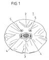
- FIG. 1 shows an airbag 1, which is designed for use as a driver's gas bag (driver's airbag).
- the airbag 1 is spread along an extension plane coincident with the paper plane and is made of two circular Gas bag layers whose peripheral edges are sewn together, glued, woven or welded to form the gas bag.
- the gas bag 1 has a side 2, which in an inflated state of the airbag 1 in the FIG. 1 Is facing airbag module 6, not shown, or a driver who is to be protected by the inflated airbag 1, facing away.
- an injection opening 3 is centrally provided in the form of a circular opening, can be introduced through the gas for inflating the airbag 1 in the airbag 1.
- the gas bag 1 has two second outflow openings 4 which are formed on two mutually opposite edge regions of the injection opening 3 and extend along the injection opening 3 along. These two second outflow openings 4 are arranged adjacent to the injection opening 3 such that they are arranged in the inflated state of the airbag 1 in an interior 1 of the airbag module 6.
- the gas bag 1 has third outflow openings 5, which each have a distance to the center of the circular injection opening 3, which is greater than the distance of the second outflow openings 4 to the center of the injection opening 3, wherein this distance is formed so large that the third outflow openings 5 in an inflated state of the airbag 1 outside of the inner space I of the airbag module 6, in which the outer space A surrounding the airbag module are arranged.
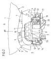
- FIG. 2 shows in connection with FIGS. 3 to 7 a partially sectioned view of the airbag module 6, which has a cover 7, which forms a receptacle for the airbag 1 of the airbag module 6 and for a gas generator 8 and a gas generator 8 surrounding chamber 9 of the airbag module 6.
- the cover 7 of the airbag module 6 separates the inner space 1 from the outer space A of the airbag module 6.
- an openable area 10 is further provided, which tears, for example, along predefined tear lines, when the gas bag 1 as a result of the building up in the gas bag 1 gas pressure along a main deployment direction of the airbag from the interior I against the openable area 10 of the cover 7 of the airbag module 6 presses.
- Under the interior I is understood to mean the space occupied by the gas bag 8 in its deflated state.
- the interior I is bounded by the unopened cover 7.
- FIG. 2 shows the airbag module 6, after the gas bag 1 (in FIG. 2 shown in section) through the openable area 10 of the cover 7 has spread out into the outer space A of the airbag module 6, wherein the third outflow openings 5 of the airbag 1 are arranged in the outer space A and the second outflow openings 4 in the interior I of the airbag module 6 are arranged.
- the flow path is in the FIG. 2 schematically indicated by corresponding arrows.
- While the gas present in the gas bag 1 can flow directly into the outer space A through the third outflow opening 5, the gas is introduced through the second outflow opening 4 first into the interior I and from there along the gas bag 1 through the openable area 10 into the exterior space A. initiated.
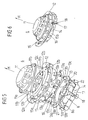
- the chamber 9 surrounding the gas generator 8 is formed by a cap-shaped diffuser 11, a generator support 12, a bottom plate 13 and a support 14 for the gas generator 8 mounted thereon in a manner capable of oscillating.
- the diffuser 11 is cap-shaped and protrudes along the main deployment direction H through the inflation opening 3 into the (inflated) gas bag 1, wherein an edge region surrounding the inflation opening 3 of the airbag 1 along the Hauptentfaltungsraum H of the airbag between a peripheral edge region 11a of the diffuser 11 and a circumferential edge region 12a, which surrounds a central opening 12c of the generator support 12 facing the injection opening 3, and is clamped between these two edge regions 11a, 12a facing one another along the main deployment direction H (gas bag clamping).
- the diffuser 11 and the generator support 12 are projected longitudinally along the main deployment direction H from the edge portion 11a of the diffuser 11 (the four fixing members 11b are arranged along the annular edge portion 11a equidistant to the respective nearest neighbor along the edge portion 11a).
- These four fasteners 11b are through corresponding holes 12 b, which are formed on the edge region 12 a of the generator support 12, out, so that free end portions of these fastening elements 11 b protrude from a side facing away from the diffuser 11 of the edge region 12 a of the generator support 12.
- the bottom plate 13 has a central circular gas generator recess 13 c, which lies along the main deployment direction H of the central opening 12 c of the generator support 12 and the injection port 3 of the airbag 1 opposite.
- this gas generator recess 13 c of the bottom plate 13 of the substantially cylindrical gas generator 8 is introduced along the main deployment direction H.
- the gas generator 8 is connected via a projecting from the gas generator 8 transversely to the main deployment direction H flange 8 a, which circulates the gas generator 8 transversely to the main deployment direction H, vibrationally connected to a trough-shaped carrier 14.
- a vibratory connection of the gas generator 8 via the flange 8a to the carrier 14 is not absolutely necessary.
- the flange 8a itself can be formed as a carrier 14, so that the carrier 14 and the gas generator 8 are connected directly to each other.
- the carrier 14 is fixed to free ends of the end portions of the fastening means 11 b, which are guided through the holes 13 a of the bottom plate 13, and closes the chamber 9 of the gas generator 8 at a side opposite to the diffuser 11 along the main deployment direction H.
- the generator support 12 furthermore has a cylindrical wall 15 which is oriented perpendicular to the central opening 12c of the generator support 12 and which rotates annularly around the central opening 12b of the generator support 12 transversely to the main deployment direction H.
- a plurality of first outflow openings 15a are formed, which can be closed or opened by means of a movable element in the form of a cylindrical ring 16.
- the cylindrical ring 16 is formed such that it bears against an inner side of the cylindrical wall 15 facing the gas generator 8 and is displaceable between two positions along a direction of movement B extending transversely to the main deployment direction H, which rotates the cylindrical wall 15 transversely to the main deployment direction H. That is, the cylindrical ring 16 can be rotated about its cylinder axis coincident with the main deployment direction H.
- Recesses 16a of the shape of the outflow openings 15a of the wall 15 are provided on the ring 16, which are arranged along the cylindrical ring 16 such that they can be completely brought into coincidence with the first outflow openings 15a of the wall 15.
- the first outflow openings 15a are fully open, so that provided by the gas generator 8 gases can pass through the first outflow openings 15a in the interior I and from there into the outer space A of the airbag module 6.
- the recesses 16a of the ring 16 can be brought out of register with the first outflow openings 15a of the wall 15 of the generator carrier 12. In this case, the first outflow openings 15 a are completely closed by the ring 16.
- a motion-generating device 17 is arranged on the bottom plate 13 FIG. 7 provided in the form of a pyrotechnic actuator.
- the movement generating device 17 has according to FIG. 7 an igniter 18, which is controlled by means of control electronics, that is, ignited and in a pressure chamber 19 which is formed in the bottom plate 13, can generate an overpressure, the one movably mounted in the pressure chamber 19, longitudinally extending piston 20 along the direction of movement B can push out of the pressure chamber 19.
- the piston 20 is arranged along the direction of movement B in a recess 21 of the ring 16, which interrupts the ring 16 along the direction of movement B, wherein the piston 20 is arranged such that it passes through an overpressure provided in the pressure chamber 19 of the Moving direction B presses against a transverse to the direction of movement B extending edge 22 of the recess 21 of the ring 16 so that it is rotated to open the first outflow openings 15 a along the direction of movement B against the wall 15.
- the recess 21 can also be a recess 16a of the ring 16.
- the piston 20 along the direction of movement B between the piston 20 facing the edge 22 of the recess 21 and the edge 22 along the direction of movement B opposite further edge of the recess 21 is arranged, in such a way that it can press tangentially to the ring 16 against its facing edge 22 of the ring 16.
- deformations are reduced, which can occur when such a piston 20 radially spaced from the ring 16 presses against a projecting portion of the ring for rotating the ring relative to the wall 15. That is, by the above-described arrangement of the piston 20, the ring 16 can be manufactured material and weight optimized.
- the ring 16 can be safely displaced along the wall 15 of the generator support 12 by the piston 20, 13 guide means are provided on the generator support 12 and / or the bottom plate, which guide the cylindrical ring 16 along the direction of movement B.
- the bottom plate 13 has such a guide means, in the form of a gas generator recess 13 c circumferential stage along which a bottom plate 13 facing edge of the ring 16 can slide.
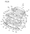
- FIG. 8 shows a modification of the in FIG. 5 shown airbag module 6, in which, in contrast to FIG. 5 the ring 16 is not interrupted by the recess 21 along the direction of movement B.
- the recess 21 of the ring 16 is here formed on the bottom plate 13 facing edge of the ring 16, in such a way that also a transverse to the direction B extending edge 22 of the recess 21 is formed, against which the piston 20 for moving the ring sixteenth can press.
- FIG. 8 illustrated modification of the airbag module 6 of the ring 16 is not as in the FIG.
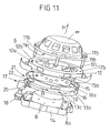
- FIG. 9 shows in connection with FIG. 10 and FIG. 11 another variation of the in the FIG. 5 respectively.
- FIG. 8 shown airbag module 6, in which, in contrast to FIG. 5 respectively.
- FIG. 8 a recess 21 is provided on the ring 16, which does not interrupt the ring 16, ie, the ring 16 is formed closed in itself, so that the piston 20, which presses against the edge 22 of this recess 21 for moving the ring 16, the Ring 16 slides along the direction of movement B. So that the ring 16 is less strongly deformed in this case by the piston 20 when moving relative to the wall 15, it has perpendicular to the direction of movement B a substantially U-shaped cross section or a comparable profiling.
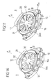
- FIG. 12 shows in connection with FIG. 13 and FIG. 14 an alternative variant of an airbag module 6, in which, in contrast to FIG. 5 .
- FIG. 8 and FIG. 11 the movable element is not formed by a ring 16, but by the gas generator 8 itself Figures 5 . 8th and 11 can be dispensed with a bottom plate 13 here.
- the chamber 9 surrounding the gas generator 8 is formed in this case by at least a first and a second chamber element, namely the generator support 12 as the first chamber element, which lies opposite the trough-shaped support 14 as the second chamber element along the main deployment direction H, at which a central Gasgeneratoraus strictlyung 14a, through which a free end region of the gas generator 8 projects along the main deployment direction H, the gas generator 8 having a gas generator 8 and projecting from the gas generator 8 flange 8a, via which the gas generator 8 is mounted on a gas generator recess 14a peripheral edge region is, along the main deployment direction H of a blowing port 3, not shown, of the airbag module 1 of the airbag module 6 is opposite and facing it.
- the carrier 14 has a circumferential edge region 14c, which faces the generator carrier 12 along the main deployment direction H and can rest against it for forming the chamber 9 surrounding the gas generator 8.
- the cap-shaped diffuser 11 On the central opening 12c of the generator support 12 sits the cap-shaped diffuser 11, wherein as described above, between the diffuser 11 and the generator support 12 of the airbag 1 is clamped with its the inflation opening 3 peripheral edge region. From the diffuser 11 are, as described above, from fastening elements 11b, which are aligned with the fastening elements 11b aligned holes 12b of the generator support 12 and these holes 12b aligned holes 14b of the carrier 14 and with the holes 14b of the carrier 14 aligned slots 24a of a locking element 24 are guided and with along the main deployment direction H longitudinally extending trained nuts 25 are screwed.
- the nuts 25 are formed so that they are inserted in a bolted to the fastening means 11 b along the main deployment direction H in the slots 24 a of the locking element 24 and aligned with the fastening elements 11 b holes 14 b of the support 14, so that the support 14 along the Hauptentfaltungsides H on the nuts 25 along the main deployment direction H can slide. That is, the nuts 25 constitute guide members for the gas generator 8 and the carrier 14 (second chamber member), which can be guided by the guide members 25 through a pressure acting upon inflation of the airbag 1 along a direction of movement B opposite to the main deployment direction H.
- the first outflow opening 15a is closed to fix when inflating the airbag 1, the locking element 24 is provided, which is engageable with the guide elements 25 in engagement, that the gas generator 8 with the Carrier 14 along the direction of movement B can press against the locking element 24 (due to the pressure) and is held in its initial position with respect to the injection port 3, ie, the carrier 14 connected via the flange 8a of the gas generator 8 with the gas generator 8 is located with his the generator support 12 facing edge region 14c on the generator support 12, so that along the main deployment direction H between the carrier 14 and the generator support 12 no Gas or only relatively small amounts of gas from the gas generator 8 surrounding chamber 9 can escape (so it is not necessary that the edge portion 14c of the carrier 14 sealingly abuts the generator support 12).
- the piston 28 of the movement-generating device 26 is arranged with respect to the locking element 24 such that it is displaced linearly along the unlocking direction E by the piston 28.
- the locking element 24 is disengaged from notches 25a of the guide elements 25, so that the gas generator 8 is spaced along the direction of movement B of the injection port 3 of the airbag 1 due to the pressure acting on inflation of the airbag 1.
- the carrier 14, which is connected to the gas generator 8, namely its edge region 14c moves away from the generator carrier 12, so that a gap surrounding the gas generator 8 is formed between the edge region 14c of the carrier 14 and the generator carrier 12, and the first outflow opening 15a forms.
- This position of the gas generator 8 and the carrier 14 is in the FIG. 12 shown.
- shows FIG. 13 shows FIG. 13 the initial position of the gas generator 8 and the carrier 14 with a voltage applied to the generator support 12 edge region 14c of the carrier 14. This corresponds to a sealed first discharge opening 15a.
- FIG. 15 shows a detail of the in the FIGS. 12 to 14 shown airbag module 6, namely the principle according to which the substantially annular locking element 24 which is the carrier 14 along the main deployment direction H opposite, with the guide elements 25 is engageable.
- the locking element 24, the elongated holes 24a which extend along the unlocking E, wherein the slots A widen along the unlocking direction E and accordingly each have a narrow portion 24c, which along the unlocking E expanded one Region 24b of a slot 24a opposite and is divided by a constriction of this flared portion 24b.
- the notches 25a of the guide elements 25 are annular and circulate the guide elements 25 transversely to the direction of movement B.
- the outer diameter of the notches 25a of the guide elements 25 is just so large that the guide elements 25 are pressed with their notches 25a in the narrow portions 24c of the slots 24a and snap through the constrictions between the narrow portions 24c and the flared portions 24b in the narrow portions 24c. In this position, the guide elements 25 can no longer be moved along the direction of movement B.
- the igniter 27 of the movement generating device 26 is ignited and the piston 28 thereby along the unlocking E is pressed against the locking member 24 so that the narrow portions 24c of the elongated holes 24a are pushed out of the notches 25a of the guide members 25 and the expanded portions 24b are displaced toward the guide members 25.
- the locking member 24 is disengaged from the notches 25a of the guide members 25 because the outer diameter of the guide members 25 spaced apart from the notches 25a is smaller than the diameter of the expanded portions 24b of the elongated holes 24a. That is, the locking member 24 can now slide along with the carrier 14 and the gas generator 8 attached thereto along the direction of movement B on the guide elements 25.
- FIG. 16 shows in connection with FIG. 17 and FIG. 18 a perspective, fragmentary view or exploded view of an airbag module 6, the generator support 12, in contrast to the embodiments of the generator support 12 shown above, no permanently open central opening 12c, but a plurality of radially arranged outflow openings 29, through the gas from the chamber 9 of the airbag module 26 can pass through the injection opening 3 in the airbag 1.
- these outflow openings 29 face along the main deployment direction H of the airbag 1 of the injection opening 3 and are opposite this along the main deployment direction H.
- the outflow openings 29 may be formed in such a way that the gas which passes through these outflow openings 29 for inflating the airbag 1, is swirled by the special design of the outflow openings 29, so that the diffuser 11 is dispensable. That is, in the FIGS. 16 to 18 shown airbag module 6 has only a clamping ring 30, on which the generator carrier 12 facing edge region 11a is formed (see FIG. 5 ), which presses an edge portion of the airbag 1 surrounding the inflation opening 3 against the generator support 12 and thus fixes the airbag 1 to the generator support 12.
- clamping ring 30 stand along the main deployment direction H from the fastening elements 11b, according to the embodiments of the airbag module 6 described above.
- valve plate 32 is formed, which has a plurality of openings 32a, which can be brought into coincidence with the outflow openings 29 of the Ausström Symposiumes 31 of the generator carrier 12.
- valve plate 32 together with the attached thereto ring 16 (ring 16 and valve plate 32 may be integrally formed) along a direction transverse to the main deployment direction H extending direction of movement B are rotated, ie, the valve plate 32 may be about an axis perpendicular to the valve plate 32 axis , which coincides with the main deployment direction H, are rotated, wherein the openings 32a of the valve plate 32 can be made to coincide with the outflow openings 29 of the outflow region 31 - the outflow openings 29 are opened - or the outflow openings 29 are completely closable by means of the valve plate 32. Since the valve plate 32 is coupled to the ring 16, the valve plate 32 via the in the FIGS.
- the outflow openings 29 are formed on the outflow region 31 of the generator carrier 12 such that when the outlet openings 29 are closed by the valve plate 32, the first outflow openings 15a of the cylindrical wall 15 of the generator carrier 12 are opened and the outflow openings 15a are closed by the ring 16, if the Outflow openings 29 are opened, that is, with the openings 32 a formed on the valve plate 32 are in coincidence.
- the gas generator 8 may, for example, according to FIG. 14 be formed to be movable along the direction of movement B, wherein additionally the central opening 12c of the generator support 12 through a discharge area 31 with corresponding outflow openings 29 according to the FIG. 18 can be equipped, so that in the FIG. 14 illustrated central opening 12b of the generator carrier 12 by means of a valve plate 32 is closed.
- a respective movement generating device according to the FIG. 7 intended.
Description
Die Erfindung betrifft ein Airbagmodul für ein Kraftfahrzeug gemäß dem Oberbegriff des Anspruchs 1. Das Dokument
Der Erfindung liegt die Aufgabe zugrunde, das Aufblasverhalten eines Airbagmoduls der eingangs genannten Art zu verbessern.The invention has for its object to improve the inflation of an airbag module of the type mentioned.
Dieses Problem wird durch ein Airbagmodul mit den Merkmalen des Anspruchs 1 gelöst.This problem is solved by an airbag module having the features of
Danach weist das Airbagmodul eine erste Abströmöffnung auf, der ein zumindest zwischen zwei unterschiedlichen Positionen bewegbares Element zugeordnet ist, durch dessen Bewegung zwischen den beiden Positionen die erste Abströmöffnung derart gasleitend mit der Gasaustrittsöffnung des Gasgenerators verbindbar ist, dass das durch die Gasaustrittsöffnung ausströmende Gas zumindest teilweise in den Außenraum geleitet wird.Thereafter, the airbag module has a first outflow opening, which is associated with at least one movable element between two positions by the movement between the two positions, the first outflow opening is gas-conductively connected to the gas outlet opening of the gas generator such that the gas flowing out through the gas outlet opening at least partially is directed to the outside space.
Hierdurch besteht die Möglichkeit, die erste Abströmöffnung (oder eine Mehrzahl derartiger Abströmöffnungen) in Abhängigkeit von einer jeweiligen Unfallsituation zu öffnen (bzw. zu verschließen), so dass eine Gasmenge, mit der der Gassack befüllt ist, an die jeweilige Unfallsituation anpassbar ist. Bei einer oop-Situation (out-of-position situation) beispielsweise, d.h., eine durch den Gassack zu schützende Person ist z.B. entlang einer Hauptentfaltungsrichtung des Gassackes nicht ausreichend vom Gassack entfernt, kann somit frühzeitig die erste Abströmöffnung geöffnet werden, so dass die zu schützende Person nicht durch einen zu stark aufgeblasenen Gassack verletzt wird.This makes it possible to open (or close) the first outflow opening (or a plurality of such outflow openings) as a function of a respective accident situation, so that a gas quantity with which the gas bag is filled can be adapted to the respective accident situation. In an oop situation (out-of-position situation), for example, ie, a person to be protected by the gas bag is eg along a main deployment direction of the gas bag is not sufficiently removed from the gas bag, thus early the first discharge opening can be opened so that the person to be protected is not injured by a too inflated airbag.
Auf Grund der Anpassung der Rückhalteperformance eines solchen Airbagmodulkonzeptes über den Zeitpunkt eines Öffnens der ersten Abströmöffnung (dieser Zeitspunkt stellt einen einfach kontrollierbaren Parameter einer zum Steuern der ersten Abströmöffnung verwendeten Software dar), kann ein derartiges Airbagmodul fahrzeugflottenübergreifend auf einfachste Weise angepasst und eingesetzt werden. Dies gilt auch für eine wechselnde Motorisierung im jeweiligen Fahrzeug und für die Anpassung an unterschiedliche gesetzliche Vorgaben und Verbrauchertests.Due to the adaptation of the restraining performance of such an airbag module concept over the time of opening the first outflow opening (this point in time represents an easily controllable parameter of a software used to control the first outflow opening), such an airbag module across vehicle fleets can be easily adapted and used. This also applies to a changing engine in each vehicle and for adaptation to different legal requirements and consumer tests.
Vorzugsweise ist mittels des bewegbaren Elementes die Gasaustrittsöffnung des Gasgenerators derart mit der ersten Abströmöffnung gasleitend verbindbar, dass das durch die Gasaustrittsöffnung ausströmende Gas vollständig in den das Airbagmodul umgebenden Außenraum geleitet wird. Somit kann ein Aufblasen des Gassackes, beispielsweise im Falle eine oop-Situation vollständig unterbunden werden.Preferably, by means of the movable element, the gas outlet opening of the gas generator can be connected in a gas-conducting manner to the first outflow opening such that the gas flowing out through the gas outlet opening is conducted completely into the outer space surrounding the airbag module. Thus, inflation of the gas bag, for example, in the case of an oop situation can be completely prevented.
Die Erfindung sieht eine Abdeckung des Airbagmoduls vor, die den Gassackes überdeckt und einen Innenraum des Airbagmoduls von einem das Airbagmodul umgebenden Außenraum trennt. Bei einem Fahrerairbagmodul zu Anordnung in einem Lenkrad kann es sich bei einer derartigen Abdeckung beispielsweise um eine Abdeckung eines Nabenkörpers des Lenkrades handeln.The invention provides for a cover of the airbag module, which covers the airbag and separates an interior of the airbag module from an outer space surrounding the airbag module. In a driver airbag module for arrangement in a steering wheel, such a cover may be, for example, a cover of a hub body of the steering wheel.
Die Abdeckung weist einen öffenbaren Bereich auf, durch den der Gassack in den Außenraum des Airbagmoduls entfaltbar ist. Der öffenbare Bereich kann beispielsweise Aufreißlinien aufweisen, entlang derer der öffenbare Bereich der Abdeckung durch den sich entfaltenden Gassack, der beim Aufblasen entlang einer Hauptentfaltungsrichtung gegen die Abdeckung drückt, aufreißt.The cover has an openable area through which the gas bag can be deployed into the exterior space of the airbag module. For example, the openable area may have tear lines along which the openable area of the cover ruptures due to the deploying gas bag pressing against the cover when inflated along a main deployment direction.
In der Erfindung ist vorgesehen, dass die Zweite Abströmöffnung derart im Innenraum des Airbagmoduls angeordnet ist, dass das Gas durch den öffenbaren Bereich hindurch in den Außenraum gelangt. Eine Verletzungsgefahr für eine Person besteht hierbei nicht, da der öffenbare Bereich durch den sich entfaltenden Gassack abgedeckt wird. Zusätzlich besteht beispielsweise bei einem Fahrerairbag Designfreiheit was eine dem Fahrer abgewandet Seite der Lenksäule bzw. eines Lenkrades anbelangt, da diese bei einem Abströmen von Gas durch einen in Richtung eines Fahrers geöffneten öffenbaren Bereich einer Abdeckung des Airbagmoduls nicht strömungsoptimiert bzw. hitzebeständig aufgebaut werden muss.In the invention, it is provided that the second outflow opening is arranged in the interior of the airbag module such that the gas passes through the openable area into the exterior space. A risk of injury to a person does not exist here, since the openable area is covered by the unfolding gas bag. In addition, for example, there is a driver's airbag Design freedom as far as a side facing away from the driver of the steering column or a steering wheel, since it must not be flow-optimized or heat-resistant constructed in a gas flowing out through an openable area of a cover of the airbag module in the direction of a driver.
Bevorzugt ist das bewegbare Element derart im Airbagmodul gelagert, dass es in einer parallel zur Hauptentfaltungsrichtung des Gassackes verlaufenden Bewegungsrichtung verschiebbar ist.Preferably, the movable element is mounted in the airbag module such that it is displaceable in a direction of movement parallel to the main deployment direction of the airbag.
Weiterhin ist bevorzugt das bewegbare Element derart gelagert, dass es in einer parallel zu der Einblasöffnung verlaufenden Bewegungsrichtung verschiebbar und / oder drehbar ist.Furthermore, the movable element is preferably mounted such that it is displaceable and / or rotatable in a direction of movement extending parallel to the injection opening.
Das Airbagmodul weist eine Kammer auf, die den Gasgenerator des Airbagmoduls umgibt. Die Kammer dient einerseits zum Schutz des Gassackes und hat andererseits öffenbare (verschließbare) Abströmöffnungen (zum Einleiten von Gas in den Außenraum) bzw. Ausströmöffnung (zum Einleiten von Gas in den Gassack) aufweisen oder kann durch Bewegungen von Bestandteilen der Kammer derartige Abströmöffnungen ausbilden.The airbag module has a chamber which surrounds the gas generator of the airbag module. On the one hand, the chamber serves to protect the gas bag and, on the other hand, has openable (closable) outflow openings (for introducing gas into the exterior space) or outflow opening (for introducing gas into the gas bag) or can form such outflow openings by movements of components of the chamber.
In einem Ausführungsbeispiel der Erfindung wird das bewegbare Element zumindest durch den Gasgenerator gebildet, wobei bevorzugt der Gasgenerator derart an der Kammer festgelegt ist, dass durch eine Bewegung des Gasgenerators entlang der Bewegungsrichtung die erste Abströmöffnung geöffnet wird.In one embodiment of the invention, the movable element is formed at least by the gas generator, wherein preferably the gas generator is fixed to the chamber such that the first outflow opening is opened by a movement of the gas generator along the direction of movement.
Vorzugsweise ist der Gasgenerator derart ausgebildet, dass die Bewegung des Gasgenerators entlang der Bewegungsrichtung durch einen beim Ausströmen des Gases erzeugten Druck bewirkt wird.Preferably, the gas generator is designed such that the movement of the gas generator along the direction of movement is effected by a pressure generated during the outflow of the gas.
Bevorzugt wird die den Gasgenerator umgebende Kammer zumindest durch ein erstes und ein zweites Kammerelement gebildet, wobei eines der beiden Kammerelemente mit dem Gasgenerator verbunden ist, und wobei die beiden Kammerelemente eine Aufnahme für den Gasgenerator bilden und entlang der Bewegungsrichtung beweglich zueinander gelagert sind, so dass sie entlang der Bewegungsrichtung des Gasgenerators voneinander weg bewegt werden können, wodurch die erste Abströmöffnung beispielsweise in Form eines den Gasgenerator umlaufenden Spaltes an der Kammer, d.h., zwischen zwei einander entlang der Bewegungsrichtung zugewandten umlaufenden Rändern der beiden Kammerelemente, ausgebildet wird.Preferably, the chamber surrounding the gas generator is formed at least by a first and a second chamber member, wherein one of the two chamber elements is connected to the gas generator, and wherein the two chamber elements form a receptacle for the gas generator and are movably mounted to each other along the direction of movement, so that They can be moved away from each other along the direction of movement of the gas generator, whereby the first Outflow opening, for example, in the form of a gap surrounding the gas generator to the chamber, that is, between two mutually along the direction of movement facing circumferential edges of the two chamber elements is formed.
Vorzugsweise sind die beiden Kammerelemente über entlang der Bewegungsrichtung längs erstreckt verlaufende Führungselemente beweglich zueinander gelagert. Derartige Führungselemente können beispielsweise einstückig mit einem der beiden Kammerelemente verbunden sein und entlang der Bewegungsrichtung von diesem Kammerelement oder einer weiteren Komponente der Kammer abstehen. Das andere Kammerelement kann dann über Ausnehmungen (z.B. durchgängige Löcher) verfügen, in die diese Führungselemente eingreifen, so dass dieses andere Kammerelement entlang der Bewegungsrichtung beweglich auf den Führungselementen gelagert ist, d.h., die Führungselemente gleiten durch die Ausnehmungen.The two chamber elements are preferably mounted so as to be movable relative to one another via guide elements extending along the direction of movement. Such guide elements may for example be integrally connected to one of the two chamber elements and protrude along the direction of movement of this chamber element or another component of the chamber. The other chamber member may then have recesses (e.g., through holes) into which these guide members engage so that this other chamber member is movably supported along the direction of travel on the guide members, i.e., the guide members slide through the recesses.
In einer Variante der Erfindung ist vorgesehen, dass der Gassack an dem ersten Kammerelement festgelegt ist, während der Gasgenerator an dem zweiten Kammerelement festgelegt ist. Bei einem Fahrerairbag ist das erste Kammerelement, an dem der Gassack befestigt ist, entlang der Hauptentfaltungsrichtung des Gassackes zwischen dem zweiten Kammerelement und einem durch den Gassack zu schützenden Fahrer angeordnet.In a variant of the invention it is provided that the gas bag is fixed to the first chamber element, while the gas generator is fixed to the second chamber element. In a driver's airbag, the first chamber element, to which the gas bag is attached, is arranged along the main deployment direction of the gas bag between the second chamber element and a driver to be protected by the gas bag.
Besonders bevorzugt ist der Gasgenerator derart an dem zweiten Kammerelement befestigt, dass dieses durch eine Bewegung des Gasgenerators entlang der Bewegungsrichtung des Gasgenerators vom ersten Kammerelement beabstandet wird, wobei sich entlang der Bewegungsrichtung zwischen den beiden Kammerelementen die erste Abströmöffnung, beispielsweise in Form eines den Gasgenerator quer zur Bewegungsrichtung umlaufenden Spaltes, ausbildet. D.h., die erste Abströmöffnung wird durch dieses Auseinanderbewegen der beiden Kammerelemente geöffnet.Particularly preferably, the gas generator is attached to the second chamber member, that this is spaced by movement of the gas generator along the direction of movement of the gas generator from the first chamber element, wherein along the direction of movement between the two chamber elements, the first outflow opening, for example in the form of a gas generator across to the movement direction circumferential gap forms. That is, the first outflow opening is opened by this movement apart of the two chamber elements.
In einer Variante der Erfindung ist ein lösbares Verriegelungselement vorgesehen, das zum Festlegen des Gasgenerators dient. Dieses kann beim Aufblasen des Gassackes den Gasgenerator in seiner anfänglichen Position fixieren und ist durch eine Steuerelektronik ansteuerbar, so dass abhängig von einer spezifischen Unfallsituation zu einem bestimmten Zeitpunkt eine Entriegelung des Verriegelungselementes erfolgen kann. Der Gasgenerator, der aufgrund des beim Ausströmen von Gas entstehenden Druckes gegen das Verriegelungselement drückt, bewegt sich nach einem Lösen oder Entriegeln des Verriegelungselementes, dem Druck folgend, entlang der Bewegungsrichtung von der Einblasöffnung des Gassackes weg in eine weitere Position, die entlang der Bewegungsrichtung von der anfänglichen Position beabstandet ist.In a variant of the invention, a releasable locking element is provided, which serves for fixing the gas generator. This can fix the gas generator in its initial position when inflating the airbag and can be controlled by control electronics, so that depending on a specific accident situation at a certain time unlocking of the locking element can be done. The gas generator, which arises due to the gas flowing out Pressure against the locking member, after releasing or unlocking the locking member, following the pressure, moves along the direction of travel away from the inflation opening of the airbag to a further position spaced along the direction of travel from the initial position.
Vorzugsweise ist das Verriegelungselement derart ausgebildet, dass es zum Festlegen des Gasgenerators mit den Führungselementen in Eingriff bringbar ist (das Verriegelungselement kann beispielsweise formschlüssig an den Führungselementen einrasten).Preferably, the locking element is designed such that it can be brought into engagement with the guide elements for securing the gas generator (the locking element can, for example, engage in a form-fitting manner on the guide elements).
Besonders bevorzugt ist das Verriegelungselement dazu eingerichtet und vorgesehen durch eine lineare Bewegung entlang einer quer zur Bewegungsrichtung des Gasgenerators verlaufenden Entriegelungsrichtung zumindest teilweise außer Eingriff mit den Führungselementen gebracht zu werden. Vorzugsweise weist das Verriegelungselement hierbei entlang der Entriegelungsrichtung längs erstreckte, das Entriegelungselement entlang der Bewegungsrichtung durchstoßende Langlöcher auf, an denen die Führungselemente zum Festlegen des Generators einrasten. Hierzu können diese Langlöcher sich entlang der Entriegelungsrichtung aufweiten, wobei die Führungselemente entlang der Bewegungsrichtung in aufgeweitete Bereiche dieser Langlöcher einführbar sind und Einkerbungen aufweisen, in die das Verriegelungselement, und zwar mit Randbereichen, die die Langlöcher an ihren jeweiligen schmalen Bereichen beranden, derart eingreifen kann, dass die Führungselemente entlang der Bewegungsrichtung gegen diese Randbereiche drücken und daher entlang der Bewegungsrichtung festgelegt sind.Particularly preferably, the locking element is configured and provided to be brought at least partially out of engagement with the guide elements by a linear movement along a transverse to the direction of movement of the gas generator unlocking. Preferably, the locking element in this case along the unlocking longitudinally extended, the unlocking along the direction of movement piercing slots on which engage the guide elements to set the generator. For this purpose, these elongated holes can widen along the unlocking direction, wherein the guide elements along the direction of movement in expanded portions of these slots are insertable and have notches, in which the locking element, with edge regions that bound the slots at their respective narrow areas, so intervene in that the guide elements press against these edge regions along the direction of movement and are therefore fixed along the direction of movement.
Ein schmaler und ein entlang der Entriegelungsrichtung gegenüberliegender aufgeweiter Bereich eines Langloches können durch eine Engstelle oder Verengung des Langloches quer zur Entriegelungsrichtung voneinander abgeteilt sein. Dies ist vorteilhaft, da hierdurch ein Führungselement mit seiner ringförmig umlaufenden Einkerbung in den schmalen Bereich einpressbar ist und dort durch die Engstelle gehalten wird. Ein Verschieben eines in einem schmalen Bereich befindlichen Führungselementes entlang der Entriegelungsrichtung in einen aufgeweiteten Bereich eines Langloches setzt somit eine vordefinierbare Mindestkraft voraus und vermindert somit die Gefahr eines unbeabsichtigten Entriegelns des Verriegelungselementes.A narrow and an expanded region of an oblong hole opposite the direction of unlocking can be separated from one another by a constriction or narrowing of the oblong hole transversely to the unlocking direction. This is advantageous, since in this way a guide element with its annular circumferential notch can be pressed into the narrow region and is held there by the constriction. Moving a guide element located in a narrow area along the unlocking direction into a widened region of a slot thus presupposes a predefinable minimum force and thus reduces the risk of unintentional unlocking of the locking element.
In einer Variante der Erfindung ist eine Bewegungserzeugungsvorrichtung vorgesehen, die die lineare Bewegung des Verriegelungselementes zum Lösen des Verriegelungselementes erzeugt. Hierbei weist diese Bewegungserzeugungsvorrichtung bevorzugt einen Kolben auf, der entlang der Entriegelungsrichtung gegen das Verriegelungselement drückt, wobei die Führungselemente aus den schmalen Bereichen der Langlöcher in die aufgeweiteten Bereiche dieser Langlöcher verlagert werden, so dass sie quer zur Entriegelungsrichtung, d. h., entlang der Bewegungsrichtung in den Langlöchern gleiten können. An den Verriegelungselementen können entlang der Bewegungsrichtung Verbreiterungen ausgebildet sein, so dass das Verriegelungselement beim Gleiten entlang der Führungselemente nicht völlig außer Eingriff mit den Führungselementen gerät. Es existiert somit ein maximal möglicher Abstand zwischen den beiden Kammerelementen entlang der Bewegungsrichtung.In a variant of the invention, a movement generating device is provided which generates the linear movement of the locking element for releasing the locking element. In this case, this movement-generating device preferably has a piston which presses against the locking element along the unlocking direction, wherein the guide elements are displaced from the narrow areas of the elongated holes into the widened areas of these elongated holes so that they extend transversely to the unlocking direction, i. h., Can slide along the direction of movement in the slots. At the locking elements can be formed along the direction of travel broadening, so that the locking element when sliding along the guide elements not completely disengaged from the guide elements. Thus, there is a maximum possible distance between the two chamber elements along the direction of movement.
In einer alternativen Variante der Erfindung ist die erste Abströmöffnung oder eine Mehrzahl derartiger erster Abströmöffnungen an einer den Gasgenerator umgebenen Kammer ausgebildet, wobei der Gasgenerator bezüglich der Einblasöffnung eine feste Position aufweist (mit Ausnahme von Ausgleichsbewegungen die durch eine schwingungsfähige Lagerung des Gasgenerators möglich sind).In an alternative variant of the invention, the first outflow opening or a plurality of such first outflow openings is formed on a chamber surrounding the gas generator, the gas generator having a fixed position with respect to the injection opening (with the exception of compensating movements which are possible by means of a vibratory mounting of the gas generator).
Vorzugsweise ist hierbei das bewegbare Element derart beweglich an dieser Kammer gelagert, dass die erste Abströmöffnung mittels des bewegbaren Elementes verschließbar bzw. öffenbar ist.Preferably, in this case, the movable element is mounted so movably on this chamber, that the first outflow opening by means of the movable element can be closed or opened.
In einer Variante der Erfindung ist vorgesehen, dass die Kammer des Gasgenerators eine zylindrische Wandung aufweist, in der die erste Abströmöffnung angeordnet ist. Hierbei kann diese zylindrische Wandung den Gasgenerator quer zur Hauptentfaltungsrichtung des Gassackes des Airbagmoduls umlaufen. In diesem Fall ist die Gasaustrittsöffnung des Gasgenerators (oder einer Mehrzahl derartiger Gasaustrittsöffnungen) der ersten Abströmöffnung (bzw. einer entsprechenden Mehrzahl derartiger erster Abströmöffnungen) quer zur Hauptentfaltungsrichtung des Gassackes zugewandt, so dass das Gas zunächst quer zur Hauptentfaltungsrichtung aus der den Gasgenerator umgebenden Kammer abströmen kann.In a variant of the invention it is provided that the chamber of the gas generator has a cylindrical wall in which the first outflow opening is arranged. In this case, this cylindrical wall can rotate the gas generator transversely to the main deployment direction of the gas bag of the airbag module. In this case, the gas outlet opening of the gas generator (or a plurality of such gas outlet openings) of the first outflow opening (or a corresponding plurality of such first outflow openings) transverse to the main deployment direction of the airbag, so that the gas initially flow out transversely to the main deployment direction from the chamber surrounding the gas generator can.
Vorzugsweise weist das bewegbare Element einen zylindrischen Ring mit einer Aussparung auf, wobei der Ring derart verschiebbar an der Wandung der Kammer gelagert ist, dass die Aussparung durch ein Verschieben des Ringes entlang der Wandung mit der ersten Abströmöffnung in Deckung bringbar ist. Hierbei kann die Aussparung des Ringes die Form und Größe der ersten Abströmöffnung aufweisen. Bei einer Mehrzahl von ersten Abströmöffnungen, die entlang der zylindrischen Wandung ausgebildet sein können, weist der zylindrische Ring eine entsprechende Mehrzahl von Aussparungen auf, die durch ein Verschieben des Ringes entlang der Wandung mit diesen ersten Abströmöffnungen in Deckung bringbar sind. Unter einem Verschieben des Ringes wird hierbei eine Rotation eines zylindrischen Ringes um seine Zylinderachse verstanden, d.h., der zylindrische Ring kann an der Wandung anliegen und gegen die Wandung verdreht werden. Allerdings ist eine Translation des Ringes nicht ausgeschlossen und ebenso möglich (auch in Kombination mit einer Rotation).Preferably, the movable member has a cylindrical ring with a recess, the ring being displaceable on the wall of the chamber is mounted, that the recess by a displacement of the ring along the wall with the first outflow opening can be brought into coincidence. In this case, the recess of the ring may have the shape and size of the first outflow opening. In a plurality of first outflow openings, which may be formed along the cylindrical wall, the cylindrical ring has a corresponding plurality of recesses, which can be brought into coincidence by a displacement of the ring along the wall with these first outflow openings. Under a displacement of the ring is in this case understood a rotation of a cylindrical ring about its cylinder axis, ie, the cylindrical ring can rest against the wall and be rotated against the wall. However, a translation of the ring is not excluded and also possible (also in combination with a rotation).
Die Aussparung (oder die Aussparungen) des Ringes sind derart am Ring ausgebildet, dass der Ring bezüglich der Wandung der Kammer in eine Position dreh- bzw. schiebbar ist, in der der Ring die erste Abströmöffnung (oder die Mehrzahl an ersten Abströmöffnungen) vollständig verschließt. Ebenso können die Aussparungen derart am Ring angeordnet sein, dass in einer bestimmten Position des Ringes bezüglich der Wandung sämtliche erste Abströmöffnungen der Wandung geöffnet sind.The recess (or recesses) of the ring are formed on the ring so that the ring is rotatable with respect to the wall of the chamber to a position in which the ring completely closes the first outflow opening (or the plurality of first outflow openings) , Likewise, the recesses may be arranged on the ring, that in a certain position of the ring with respect to the wall, all first outflow openings of the wall are open.
Besonders bevorzugt weist der Ring zum Verschieben des Ringes entlang der Bewegungsrichtung eine Ausnehmung mit einem quer zur Bewegungsrichtung erstreckten Rand auf (bei einer zylindrischen Wandung umläuft die Bewegungsrichtung die zylindrische Wandung bevorzugt quer zur Hauptentfaltungsrichtung des Gassackes, d.h., quer zur Zylinderachse der zylindrischen Wandung). In einer Variante der Erfindung ist diese Ausnehmung als ein den Ring unterbrechender Spalt ausgebildet (offener Ring), der sich quer zur Bewegungsrichtung erstreckt.Particularly preferably, the ring for moving the ring along the direction of movement has a recess with an edge extending transversely to the direction of movement (in a cylindrical wall, the direction of movement preferably rotates the cylindrical wall transversely to the main deployment direction of the airbag, i.e. transverse to the cylindrical axis of the cylindrical wall). In a variant of the invention, this recess is formed as a gap interrupting the ring (open ring), which extends transversely to the direction of movement.
Vorzugsweise drückt ein Kolben einer Bewegungserzeugungsvorrichtung entlang der Bewegungsrichtung gegen den Rand der Ausnehmung, so dass der Ring durch den Kolben aus einer anfänglichen Position, in der die erste Abströmöffnung durch den Ring verschlossen ist, in eine weitere Position geschoben wird, in der die erste Abströmöffnung geöffnet ist. Durch diese vorteilhafte tangentiale Krafteinleitung wird der Ring nur gering deformiert. Zur Verstärkung der Ringes kann die Ausnehmung an dem Ring nur partiell ausgebildet sein, d.h., den Ring senkrecht zur Bewegungsrichtung nicht vollständig durchtrennen. In diesem Fall ist weiterhin bevorzugt eine schmale, den Ring quer zur Bewegungsrichtung durchtrennende weitere Ausnehmung vorgesehen, die in der Bewegungsrichtung hinter dem Rand der Ausnehmung ausgebildet ist und entlang dieses Randes, d.h., quer zur Bewegungsrichtung, verläuft. Drückt nun der Kolben der Bewegungserzeugungsvorrichtung entlang der Bewegungsrichtung gegen den Rand der Ausnehmung, so wird der Ring aufgrund der weiteren Ausnehmung nicht entlang der Bewegungsrichtung geschoben, sondern gezogen, was eine weitere Minimierung einer durch die Kolbeneinwirkung verursachten Deformation des Ringes bedingt.Preferably, a piston of a movement generating device pushes along the direction of movement against the edge of the recess, so that the ring is pushed by the piston from an initial position in which the first outflow opening is closed by the ring in a further position in which the first outflow opening is open. This advantageous tangential force introduction of the ring is only slightly deformed. To reinforce the ring, the recess may be formed only partially on the ring, that is, not completely cut through the ring perpendicular to the direction of movement. In this case further preferred is a narrow, the ring Transversely to the direction of separation by further cutting provided, which is formed in the direction of movement behind the edge of the recess and along this edge, ie, transverse to the direction of movement extends. Now pushes the piston of the movement generating device along the direction of movement against the edge of the recess, the ring is not pushed along the direction of movement due to the further recess, but pulled, causing a further minimization caused by the action of the piston deformation of the ring.
Aufgrund der vorstehenden Minimierung der Deformation des Ringes kann dieser besonders leicht ausgebildet werden (geringe Wandstärke). Weiterhin kann die Aussparung des Ringes, die zum Öffnen der ersten Abströmöffnung mit der ersten Abströmöffnung in Deckung bringbar ist, in Folge der Minimierung der Deformation des Ringes besonders großflächig ausfallen. Die Aussparung (oder die Aussparungen) kann daher etwa die Hälfte einer der Wandung der Kammer zugewandten Fläche des Ringes einnehmen.Due to the above minimization of the deformation of the ring this can be particularly easily formed (low wall thickness). Furthermore, the recess of the ring, which can be brought to cover the first outflow opening with the first outflow opening in cover, fail due to the minimization of the deformation of the ring particularly large area. The recess (or the recesses) may therefore occupy about half of the wall of the chamber facing surface of the ring.
In einer weiteren Variante der Erfindung ist vorgesehen, dass die den Gasgenerator umgebende Kammer eine verschließbare Ausströmöffnung aufweist, durch die durch den Gasgenerator erzeugtes bzw. freigesetztes Gas zum Aufblasen des Gassackes in den Gassack gelangen kann. Bevorzugt ist die Ausströmöffnung (es kann sich hierbei auch um eine Mehrzahl von Ausströmöffnungen handeln) an einem der Einblasöffnung des Gassackes zugewandten Ausströmbereich der Kammer angeordnet.In a further variant of the invention, it is provided that the chamber surrounding the gas generator has a closable discharge opening through which gas generated or released by the gas generator can flow into the gas bag for inflating the gas bag. Preferably, the outflow opening (this can also be a plurality of outflow openings) is arranged on a discharge area of the chamber facing the injection opening of the airbag.
Besonders bevorzugt weist das bewegbare Element des Airbagmoduls eine Ventilplatte mit einer Öffnung auf, wobei die Ventilplatte derart beweglich an der Wandung der Kammer gelagert ist, dass die Öffnung durch ein Verschieben (Rotieren) der Ventilplatte entlang des Ausströmbereiches mit der Ausströmöffnung in Deckung bringbar ist. Bei einer Mehrzahl von an dem Ausströmbereich ausgebildeten Ausströmöffnungen ist an der Ventilplatte eine entsprechende Mehrzahl an Öffnungen vorgesehen, die mit den Ausströmöffnungen durch Verschieben bzw. Verdrehen der Ventilplatte in Deckung bringbar sind, wodurch die Ausströmöffnungen der Kammer geöffnet werden können.Particularly preferably, the movable element of the airbag module has a valve plate with an opening, wherein the valve plate is movably mounted on the wall of the chamber such that the opening can be brought into coincidence with the outflow opening by displacing (rotating) the valve plate along the outflow region. In a plurality of outflow openings formed at the outflow area, a corresponding plurality of openings is provided on the valve plate, which can be brought into coincidence with the outflow openings by displacement or rotation of the valve plate, whereby the outflow openings of the chamber can be opened.
Weiterhin ist die Öffnung bzw. sind die Öffnungen derart an der Ventilplatte ausgebildet, dass die Ventilplatte durch Verdrehen der Ventilplatte bezüglich des Abströmbereiches um einen vorbestimmbaren Winkel sämtliche Ausströmöffnungen des Ausströmbereiches der Kammer verschließt.Furthermore, the opening or the openings are formed on the valve plate, that the valve plate by turning the valve plate with respect to the outflow area closes all outflow openings of the discharge area of the chamber by a predeterminable angle.
In einer Variante der Erfindung ist vorgesehen, dass die Ventilplatte an einem umlaufenden, dem Gassack bzw. der Einblasöffnung des Gassackes zugewandten Rand des Ringes festgelegt ist. D.h., das bewegbare Element kann als ein flacher einseitig offener Zylinder ausgebildet sein, wobei der Ring die Zylinderwandung bildet, und wobei der eine Boden dieses Zylinders durch die (kreisförmige) Ventilplatte gebildet wird.In a variant of the invention, it is provided that the valve plate is fixed to a peripheral, the airbag or the inflation opening of the airbag facing edge of the ring. That is, the movable member may be formed as a flat cylinder open on one side, the ring forming the cylinder wall, and the one bottom of this cylinder being formed by the (circular) valve plate.
Vorzugsweise ist die Öffnung der Ventilplatte derart bezüglich der Aussparung des Ringes angeordnet, dass die Ausströmöffnung durch die Ventilplatte verschlossen ist, wenn die erste Abströmöffnung der Wandung der Kammer offen ist, wobei weiterhin vorzugsweise die Ausströmöffnung offen ist, wenn die erste Abströmöffnung durch den Ring verschlossen ist. Entsprechendes gilt für eine Mehrzahl von Öffnungen der Ventilplatte bzw. Ausströmöffnungen der Kammer und eine Mehrzahl von ersten Abströmöffnungen der Kammer bzw. Aussparungen des Ringes.Preferably, the opening of the valve plate is arranged with respect to the recess of the ring, that the outflow opening is closed by the valve plate when the first outflow opening of the wall of the chamber is open, further preferably, the outflow opening is open when the first outflow opening closed by the ring is. The same applies to a plurality of openings of the valve plate or outflow openings of the chamber and a plurality of first outflow openings of the chamber or recesses of the ring.
Die zusätzlich vorgesehenen steuerbaren Ausströmöffnungen der Kammer sind vorteilhaft, da nicht nur ein zusätzlicher Strömungsweg zur Druckentlastung des Gassackes ermöglicht wird, sondern der Weg der Gase in den Gassack vollkommen gesperrt werden kann, so dass eine weiter Verminderung der Insassenbelastung unter oop-Bedingungen möglich ist.The additionally provided controllable outflow openings of the chamber are advantageous because not only an additional flow path for pressure relief of the airbag is made possible, but the way of the gases in the airbag can be completely blocked, so that a further reduction of the occupant load under oop conditions is possible.
In einer weiteren Variante der Erfindung weist der Gassack eine zweite Abströmöffnung (oder eine entsprechende Mehrzahl von zweiten Abströmöffnungen) auf, die in einem aufgeblasenen Zustand des Gassackes derart im Innenraum des Airbagmoduls angeordnet ist, dass aus der zweiten Abströmöffnung austretenden Gas durch den offenbaren Bereich der Abdeckung des Airbagmoduls hindurch in den das Airbagmodul umgebenden Außenraum gelangen kann.In a further variant of the invention, the gas bag has a second outflow opening (or a corresponding plurality of second outflow openings) which, in an inflated state of the gas bag, is arranged in the interior of the airbag module such that gas emerging from the second outflow opening passes through the apparent area of the airbag module Cover of the airbag module can pass into the outer space surrounding the airbag module.
Dies ist vorteilhaft, da in einer oop-Situation (d.h. der Gassack ist früh verblockt) auf Grund des hohen Gasdrucks im Innenraum des Airbagmoduls ein gutes Ventilieren durch solche zweiten Abströmöffnungen möglich ist, so dass die Belastungen auf den Fahrer in einer frühen Phase der Entfaltung des Gassackes reduziert werden.This is advantageous because in an oop situation (ie the gas bag is blocked early) due to the high gas pressure in the interior of the airbag module good ventilation through such second outflow is possible, so that the burden on the driver in an early stage of deployment of the airbag are reduced.
In einer Variante der Erfindung sind Mittel -vorgesehen, die dazu ausgebildet und eingerichtet sind, zu verhindern, dass das aus den ersten und zweiten Abströmöffnungen austretende Gas entgegengesetzt zur Hauptentfaltungsrichtung H strömen kann.In a variant of the invention, means are provided which are designed and arranged to prevent the gas emerging from the first and second outflow openings from flowing in the opposite direction to the main deployment direction H.
Der Gassackweist zum Ablassen von Gas eine dritte Abströmöffnung auf, die bei einem entfalteten Gassack im Außenraum des Airbagmoduls angeordnet ist. Derartige dritte Abströmöffnungen sind vorteilhaft, da sie ein zuverlässiges Entlüften des stehenden, d.h. bereits entfalteten Gassackes, ermöglichen.The gas bag has a third outlet opening for discharging gas, which is arranged in the case of a deployed gas bag in the outer space of the airbag module. Such third outflow apertures are advantageous in that they provide reliable venting of the stagnant, i. already deployed airbag, allow.
Vorzugsweise ist die dritte Abströmöffnung im aufgeblasenen Zustand des Gassackes an einer dem Airbagmodul zugewandten Seite, d.h. einer dem Fahrer abgewandten Seite des Gassackes, angeordnet, so dass die aus dem Gassack strömenden Gase nicht direkt bzw. unverwirbelt auf den Fahrer oder eine durch den Gassack zu schützende Person gerichtet sind.Preferably, the third outflow opening in the inflated state of the airbag at a side facing the airbag module, i. a side facing away from the driver of the airbag, arranged so that the gases flowing from the gas bag are not directed directly or untwisted to the driver or a person to be protected by the gas bag.
Bevorzugt ist eine weitere dritte Abströmöffnung vorgesehen, die zum Ablassen von Gas dient und bei einem entfalteten Gassack im Außenraum des Airbagmoduls angeordnet ist. Hierbei liegt die weitere dritte Abströmöffnung vorzugsweise im aufgeblasenen Zustand des Gassackes quer zur Hauptentfaltungsrichtung des Gassackes der dritten Abströmöffnung gegenüber, so dass beispielsweise bei einem symmetrisch aufgebauten Fahrerairbag ein möglichst symmetrisches Gasabstrahlverhalten bewirkt wird und der Gassack (räumlich) gleichmäßig entlüftet werden kann.Preferably, a further third outflow opening is provided, which serves for the discharge of gas and is arranged in an unfolded airbag in the outer space of the airbag module. In this case, the further third outflow opening preferably lies in the inflated state of the airbag transverse to the main deployment direction of the airbag of the third outflow opening, so that, for example, in a symmetrically constructed driver's airbag as symmetrical Gasabstrahlverhalten is effected and the airbag (spatial) can be evenly vented.
Mit Vorteil können die ersten, zweiten und dritten Abströmöffnungen miteinander kombiniert und aufeinander abgestimmt werden. Hierbei ersetzen die zweiten und dritten Abströmöffnungen im Gassack die Standardabströmöffnungen, mit denen ein Gassack üblicherweise ausgestattet ist. Die Abstimmung der Fläche der zweiten Abströmöffnungen in Bezug auf die dritten Abströmöffnungen, d.h. die Abstimmung des Verhältnisses dieser beiden Flächen zueinander, erfolgt dergestalt, dass die so genannte in-position-performance (der Gassack kann sich frei und ungehindert entfalten) der eines bekannten Standardgassackes entspricht.Advantageously, the first, second and third outflow openings can be combined and matched to one another. In this case, the second and third outflow openings in the gas bag replace the standard outflow openings with which an airbag is usually equipped. The matching of the area of the second outflow openings with respect to the third outflow openings, i. the coordination of the ratio of these two surfaces to each other, takes place in such a way that the so-called in-position performance (the airbag can unfold freely and unhindered) corresponds to that of a known standard airbag.
Während die zweiten und dritten Abströmöffnungen permanent geöffnet sind, sind die ersten Abströmöffnungen schalt- bzw. steuerbar. D.h., das Öffnen dieser ersten Abströmöffnungen erfolgt zeitabhängig nach Zündung des Gasgenerators (beispielsweise durch eine pyrotechnische Bewegungserzeugungsvorrichtung). Bei einer frühzeitigen Öffnung dieser ersten Abströmöffnungen wird der Massenstrom des Gasgenerators unterhalb einer Gassackanbindung (beispielsweise durch Festklemmen eines die Einblasöffnung des Gassackes umlaufenden Randbereiches an einem Generatorträger) abgeblasen und damit der Füllgrad des Gassackes beeinflusst, wobei gleichzeitig durch zusätzliche zweite und dritte Abströmöffnung eine effektivere Rückhalteperformance ("weicherer" Gassack) für leichtere Insassen (5 % Frau) erzielt wird. Bei einem späteren Öffnen der schalt- bzw. steuerbaren ersten Abströmöffnungen wird die Rückhalteperformance von schweren Insassen (50 % und 95 % Mann) verbessert. Das Entfalten des Gassackes kann durch eine bessere Rechteckkennung der Beschleunigungswerte (Verzögerung) eines Fahrzeuginsassen bei einer das Airbagmodul auslösenden Unfallsituation unterstützt werden (frühzeitige Rückhaltung durch schneller Gassackbereitstellung). Insgesamt kann durch den gezielt wählbaren Zeitpunkt der Öffnung der zusätzlichen Abströmfläche (erste Abströmöffnungen) eine optimale Dämpfung des Gassackes abhängig vom Insassen eingestellt werden. Die Festlegung des Öffnungszeitpunktes kann anhand einer Insassensensierung (Größe, Gewicht, Position) sowie einer Sensierung crashabhängiger Daten (Verzögerung, Geschwindigkeit) automatisch erfolgen.While the second and third outflow openings are permanently open, the first outflow openings are switchable or controllable. That is, opening this first Outflow openings are time-dependent after ignition of the gas generator (for example, by a pyrotechnic movement generating device). With an early opening of these first outflow openings, the mass flow of the gas generator below a gas bag connection (for example, by clamping the inflation of the airbag peripheral edge region on a generator support) blown off and thus affects the degree of filling of the airbag, at the same time by additional second and third outlet more effective retention performance ("softer" gas bag) for lighter passengers (5% woman) is achieved. With a later opening of the switchable or controllable first outflow openings, the retention performance of heavy occupants (50% and 95% man) is improved. The unfolding of the airbag can be assisted by a better rectangular identification of the acceleration values (deceleration) of a vehicle occupant in the event of an accident situation triggering the airbag module (early retention by rapid provision of airbag). Overall, can be adjusted depending on the occupant by the selectively selectable time of the opening of the additional outflow surface (first outflow) optimal damping of the airbag. The determination of the opening time can be made automatically by means of an occupant sensor (size, weight, position) as well as a detection of crash-dependent data (deceleration, speed).
Bei oop-Situationen besteht die Möglichkeit, durch sehr frühzeitiges Öffnen der schaltbaren ersten Abströmöffnungen den Druck im Airbagmodul (d.h. im Gassack) zusätzlich zu minimieren, um die auf den Insassen einwirkende Belastung beim Anschießen durch den Gassack weiter zu reduzieren.In oop situations, by opening the switchable first outflow openings very early, it is possible to additionally minimize the pressure in the airbag module (i.e., in the gas bag) in order to further reduce the load on the occupant when being hit by the gas bag.
Im Gegensatz zu bekannten Airbagmodulen werden die in das Airbagmodul geleiteten Gase nicht durch Öffnungen eines Generatorträgers weiter nach unten, d.h. entlang der Lenkachse in den Lenkradkorpus geleitet, sondern entlang der Lenkachse bzw. der Hauptentfaltungsrichtung des Gassackes in Richtung des öffenbaren Bereiches der Abdeckung des Airbagmoduls umgelenkt. Der Austritt der Gase erfolgt also entlang des Gassackes durch den öffenbaren Bereich der Abdeckung. Da auch bei einer oop-Situation die airbagmodulnahen Körperpartien eines Insassen ausreichend durch den Gassack abgedeckt sind, sind Verletzungen durch die abgeströmten heißen Gase ausgeschlossen. Zusätzlich werden durch den vorstehend beschriebenen Strömungsweg durch den öffenbaren Bereich der Abdeckung keine angrenzenden Baugruppen beeinträchtigt. Zusätzliche Maßnahmen am Lenkrad zur Gewährleistung der Abströmung sind daher nicht notwendig. Gleichzeitig wird verhindert, dass z.B. die Hände am Lenkrad geschädigt werden, wie dies beispielsweise bei einer Abströmung durch das Lenkrad möglich wäre.In contrast to known airbag modules, the gases conducted into the airbag module are not guided further down through openings of a generator carrier, ie into the steering wheel body along the steering axis, but are deflected along the steering axis or the main deployment direction of the airbag in the direction of the openable region of the cover of the airbag module , The exit of the gases thus takes place along the airbag through the openable area of the cover. Since even in an oop situation, the body parts close to the airbag module of an occupant are sufficiently covered by the gas bag, injuries due to the hot gases that have flowed out are ruled out. In addition, through the flow path described above through the openable area of the cover, there are no adjacent assemblies impaired. Additional measures on the steering wheel to ensure the outflow are therefore not necessary. At the same time prevents, for example, the hands are damaged on the steering wheel, as would be possible, for example, in a flow through the steering wheel.
Weitere Vorteile und Merkmale der Erfindung werden anhand der nachfolgenden Figurenbeschreibungen von Ausführungsbeispielen deutlich werden.Further advantages and features of the invention will become apparent from the following description of exemplary embodiments.
Es zeigen:
- Fig. 1
- eine Draufsicht auf einen ausgebreiteten Gassack mit zweiten und dritten Abströmöffnungen sowie eine Einblasöffnung,
- Fig. 2
- eine schematische teilweise geschnittene Ansicht eines erfindungsgemäßen Airbagmoduls mit ersten, zweiten und dritten Abströmöffnungen,
- Fig. 3
- eine perspektivische Ansicht eines Airbagmoduls mit geschlossenen ersten Abströmöffnungen,
- Fig. 4
- eine schematische Schnittansicht des in
der Figur 3 gezeigten Airbagmoduls mit geöffneten ersten Abströmöffnungen, - Fig. 5
- eine Explosionsdarstellung des in
der Figur 3 bzw.Figur 4 - Fig. 6
- eine schematische Ansicht des in
der Figur 5 gezeigten Airbagmoduls (in einem zusammengesetzten Zustand), - Fig. 7
- eine pyrotechnische Bewegungserzeugungsvorrichtung mit einem Zünder und einem Kolben,
- Fig. 8
- eine perspektivische Explosionsansicht einer Abwandlung des in
der Figur 3 gezeigten Airbagmoduls,bis Figur 6 - Fig. 9
- eine perspektivische Ansicht einer weiteren Abwandlung eines erfindungsgemäßen Airbagmoduls mit ersten Abströmöffnungen, die zum Ablassen von Gasen geöffnet sind,
- Fig. 10
- eine perspektivische Ansicht des in der
Figur 9 gezeigten Airbagmoduls mit geschlossenen ersten Abströmöffnungen, - Fig. 11
- eine perspektivische Explosionsansicht des in der
Figur 9 und Figur 10 gezeigten Airbagmoduls, - Fig. 12
- eine weitere Variante eines erfindungsgemäßen Airbagmoduls mit einem beweglich gelagerten Gasgenerator und einer geöffneten ersten Abströmöffnung,
- Fig. 13
- eine perspektivische Ansicht des in
der Figur 12 gezeigten Airbagmoduls mit einer verschlossenen ersten Abströmöffnung, - Fig. 14
- eine perspektivische Explosionsansicht des in
der Figur 12 und Figur 13 gezeigten Airbagmoduls, - Fig. 15
- ein Detail des in
der Figur 14 gezeigten Airbagmoduls, - Fig. 16
- eine perspektivische Ansicht einer Kammer mit steuerbaren Ausströmöffnungen, die einen Gasgenerator einer Variante eines erfindungsgemäßen Airbagmoduls umgibt,
- Fig. 17
- die in
der Figur 16 gezeigte Kammer mit geöffneten Ausströmöffnungen, - Fig. 18
- eine perspektivische Explosionsansicht des in
der Figur 16 und Figur 17 gezeigten Airbagmoduls.
- Fig. 1
- a plan view of a spread airbag with second and third outlet openings and an injection port,
- Fig. 2
- 2 is a schematic partially sectioned view of an airbag module according to the invention with first, second and third outflow openings,
- Fig. 3
- a perspective view of an airbag module with closed first outflow openings,
- Fig. 4
- a schematic sectional view of the in the
FIG. 3 shown airbag module with opened first outflow openings, - Fig. 5
- an exploded view of the in the
FIG. 3 respectively.FIG. 4 shown airbag module, - Fig. 6
- a schematic view of the in the
FIG. 5 shown airbag module (in an assembled state), - Fig. 7
- a pyrotechnic motion generating device with a detonator and a piston,
- Fig. 8
- an exploded perspective view of a modification of the in
FIG. 3 to FIG. 6 shown airbag module, - Fig. 9
- 3 a perspective view of a further modification of an airbag module according to the invention with first outflow openings which are open for the discharge of gases,
- Fig. 10
- a perspective view of the in the
FIG. 9 shown airbag module with closed first outlet openings, - Fig. 11
- an exploded perspective view of the in the
FIG. 9 and FIG. 10 shown airbag module, - Fig. 12
- a further variant of an airbag module according to the invention with a movably mounted gas generator and an opened first outflow opening,
- Fig. 13
- a perspective view of the in the
FIG. 12 shown airbag module with a closed first outlet opening, - Fig. 14
- an exploded perspective view of the in the
FIG. 12 and FIG. 13 shown airbag module, - Fig. 15
- a detail of in the
FIG. 14 shown airbag module, - Fig. 16
- a perspective view of a chamber with controllable outflow openings, which surrounds a gas generator of a variant of an airbag module according to the invention,
- Fig. 17
- the in the
FIG. 16 shown chamber with open outflow openings, - Fig. 18
- an exploded perspective view of the in the
FIG. 16 and FIG. 17 shown airbag module.
Der Gassack 1 weist eine Seite 2 auf, die in einem aufgeblasenen Zustand des Gassackes 1 einem in der
An der Seite 2 des Gassackes 1 ist mittig eine Einblasöffnung 3 in Form einer kreisrunden Öffnung vorgesehen, durch die Gas zum Aufblasen des Gassackes 1 in den Gassack 1 eingeleitet werden kann.On the
Der Gassack 1 verfügt über zwei zweite Abströmöffnungen 4, die an zwei einander gegenüber liegenden Randbereichen der Einblasöffnung 3 ausgebildet sind und sich entlang der Einblasöffnung 3 längs erstrecken. Diese zwei zweiten Abströmöffnungen 4 sind derart benachbart zur Einblasöffnung 3 angeordnet, dass sie im aufgeblasenen Zustand des Gassackes 1 in einem Innenraum 1 des Airbagmoduls 6 angeordnet sind.The
Weiterhin weist der Gassack 1 dritte Abströmöffnungen 5 auf, die jeweils zum Zentrum der kreisförmigen Einblasöffnung 3 einen Abstand aufweisen, der größer ist als der Abstand der zweiten Abströmöffnungen 4 zum Zentrum der Einblasöffnung 3, wobei dieser Abstand so groß ausgebildet ist, dass die dritten Abströmöffnungen 5 in einem aufgeblasenen Zustand des Gassackes 1 außerhalb des Innenraumes I des Airbagmodules 6, und zwar in dem das Airbagmodul umgebenden Außenraum A, angeordnet sind.Furthermore, the
Die Abdeckung 7 des Airbagmoduls 6 trennt den Innenraum 1 vom Außenraum A des Airbagmoduls 6 ab. An der Abdeckung 7 des Airbagmoduls 6 ist weiterhin ein öffenbarer Bereich 10 vorgesehen, der beispielsweise entlang vordefinierter Aufreißlinien aufreißt, wenn der Gassack 1 in Folge des sich in dem Gassack 1 aufbauenden Gasdruckes entlang einer Hauptentfaltungsrichtung des Gassackes vom Innenraum I her gegen den öffenbaren Bereich 10 der Abdeckung 7 des Airbagmoduls 6 drückt. Unter dem Innenraum I wird dabei der Raum verstanden, den der Gassack 8 in seinem nicht aufgeblasenen Zustand einnimmt. Entlang der Hauptentfaltungsrichtung H des Gassackes 1 wird der Innenraum I durch die ungeöffnete Abdeckung 7 begrenzt.The
Während durch die dritte Abströmöffnung 5 das in dem Gassack 1 befindliche Gas direkt in den Außenraum A strömen kann, wird das Gas durch die zweite Abströmöffnung 4 zuerst in den Innenraum I und von dort entlang des Gassackes 1 durch den öffenbaren Bereich 10 in den Außenraum A eingeleitet.While the gas present in the
Die den Gasgenerator 8 umgebende Kammer 9 wird durch einen kappenförmigen Diffusor 11, einen Generatorträger 12, eine Bodenplatte 13 und einen Träger 14 für den daran schwingungsfähig gelagerten Gasgenerator 8 gebildet. Der Diffusor 11 ist kappenförmig ausgebildet und ragt entlang der Hauptentfaltungsrichtung H durch die Einblasöffnung 3 in den (aufgeblasenen) Gassack 1 hinein, wobei ein die Einblasöffnung 3 des Gassackes 1 umlaufender Randbereich entlang der Hauptentfaltungsrichtung H des Gassackes zwischen einem umlaufenden Randbereich 11a des Diffusors 11 und einem umlaufenden Randbereich 12a, der eine zentrale, der Einblasöffnung 3 zugewandte Öffnung 12c des Generatorträgers 12 umläuft, angeordnet ist und zwischen diesen beiden entlang der Hauptentfaltungsrichtung H einander zugewandten Randbereichen 11a, 12a eingeklemmt ist (Gassackklemmung).The chamber 9 surrounding the
Der Diffusor 11 und der Generatorträger 12 sind über vier Befestigungselemente 11b, die längs erstreckt entlang der Hauptentfaltungsrichtung H vom Randbereich 11a des Diffusors 11 abstehen (die vier Befestigungselemente 11b sind entlang des ringförmigen Randbereiches 11a äquidistant zum jeweiligen nächsten Nachbarn entlang des Randbereiches 11a angeordnet). Diese vier Befestigungselemente 11b sind durch entsprechende Löcher 12b, die am Randbereich 12a des Generatorträgers 12 ausgebildet sind, geführt, so dass freie Endabschnitte dieser Befestigungselemente 11b von einer dem Diffusor 11 abgewandten Seite des Randbereiches 12a des Generatorträgers 12 abstehen. Diese abstehenden freien Endabschnitte sind weiterhin in entsprechende (durchgängige) Löcher 13a der Bodenplatte 13 eingeführt, wobei die Löcher 13a in zylinderförmigen Befestigungsbereichen 13b der Bodenplatte 13 ausgebildet sind, die (ebenso wie die Löcher 13a) mit den Befestigungselementen 11b und der Hauptentfaltungsrichtung H fluchten.The
Die Bodenplatte 13 besitzt eine mittige kreisförmige Gasgeneratoraussparung 13c, die entlang der Hauptentfaltungsrichtung H der zentralen Öffnung 12c des Generatorträgers 12 und der Einblasöffnung 3 des Gassackes 1 gegenüber liegt.The
In diese Gasgeneratoraussparung 13c der Bodenplatte 13 ist der im Wesentlichen zylinderförmig ausgebildete Gasgenerator 8 entlang der Hauptentfaltungsrichtung H eingeführt. Der Gasgenerator 8 ist über einen von dem Gasgenerator 8 quer zur Hauptentfaltungsrichtung H abstehenden Flansch 8a, der den Gasgenerator 8 quer zur Hauptentfaltungsrichtung H umläuft, schwingungsfähig mit einem wannenförmig ausgebildeten Träger 14 verbunden. Eine schwingungsfähige Anbindung des Gasgenerators 8 über den Flansch 8a an den Träger 14 ist nicht zwingend notwendig. Weiterhin kann der Flansch 8a selbst als Träger 14 ausgeformt werden, so dass Träger 14 und Gasgenerator 8 direkt miteinander verbunden sind.In this
Der Träger 14 ist an freien Enden der Endabschnitte der Befestigungsmittel 11 b, die durch die Löcher 13a der Bodenplatte 13 geführt sind, festgelegt und verschließt die Kammer 9 des Gasgenerators 8 an einer dem Diffusor 11 entlang der Hauptentfaltungsrichtung H gegenüber liegenden Seite.The
Der Generatorträger 12 weist weiterhin eine senkrecht zur zentralen Öffnung 12c des Generatorträgers 12 orientierte zylindrische Wandung 15 auf, die die zentrale Öffnung 12b des Generatorträgers 12 quer zur Hauptentfaltungsrichtung H ringförmig umläuft. An dieser Wandung 15 des Generatorträgers 12 sind eine Mehrzahl von ersten Abströmöffnungen 15a ausgebildet, die mittels eines bewegbaren Elementes in Form eines zylindrischen Ringes 16 verschließbar bzw. öffenbar sind.The
Hierzu ist der zylindrische Ring 16 derart ausgebildet, dass er an einer dem Gasgenerator 8 zugewandten Innenseite der zylindrischen Wandung 15 anliegt und entlang einer quer zur Hauptentfaltungsrichtung H verlaufenden Bewegungsrichtung B, die die zylindrische Wandung 15 quer zur Hauptentfaltungsrichtung H umläuft, zwischen zwei Positionen verschiebbar ist, d.h., der zylindrische Ring 16 kann um seine mit der Hauptentfaltungsrichtung H zusammenfallenden Zylinderachse gedreht werden.For this purpose, the
An dem Ring 16 sind Aussparungen 16a von der Gestalt der Abströmöffnungen 15a der Wandung 15 vorgesehen, die derart entlang des zylindrischen Ringes 16 angeordnet sind, dass sie vollständig in Deckung mit den ersten Abströmöffnungen 15a der Wandung 15 bringbar sind. Im Falle zur Deckung gebrachter erster Abströmöffnungen 15a bzw. Aussparungen 16a sind die ersten Abströmöffnungen 15a vollständig geöffnet, so dass durch den Gasgenerator 8 bereitgestellte Gase durch die ersten Abströmöffnungen 15a in den Innenraum I und von dort in den Außenraum A des Airbagmoduls 6 gelangen können. Durch Drehen bzw. Verschieben des Ringes 16 können die Aussparungen 16a des Ringes 16 außer Deckung mit den ersten Abströmöffnungen 15a der Wandung 15 des Generatorträgers 12 gebracht werden. In diesem Fall sind die ersten Abströmöffnungen 15a vollständig durch den Ring 16 verschlossen.
Damit der zylindrische Ring 16 zum Öffnen der anfangs geschlossenen Abströmöffnungen 15a entlang der Bewegungsrichtung B verschoben werden kann, ist an der Bodenplatte 13 eine Bewegungserzeugungsvorrichtung 17 gemäß
Die Bewegungserzeugungsvorrichtung 17 weist gemäß
Zur Übertragung der Kolbenbewegung ist der Kolben 20 entlang der Bewegungsrichtung B in einer Ausnehmung 21 des Ringes 16 angeordnet, die den Ring 16 entlang der Bewegungsrichtung B unterbricht, wobei der Kolben 20 derart angeordnet ist, dass er durch einen in der Druckkammer 19 bereitgestellten Überdruck entlang der Bewegungsrichtung B gegen einen quer zur Bewegungsrichtung B verlaufenden Rand 22 der Ausnehmung 21 des Ringes 16 drückt, so dass dieser zum Öffnen der ersten Abströmöffnungen 15a entlang der Bewegungsrichtung B gegenüber der Wandung 15 gedreht wird. Bei der Ausnehmung 21 kann es sich auch um eine Aussparung 16a des Ringes 16 handeln.To transmit the piston movement, the
Vorteilhaft bezüglich der Anordnung des Kolbens 20 in der Ausnehmung 21 des Ringes 16 ist, dass der Kolben 20 entlang der Bewegungsrichtung B zwischen dem dem Kolben 20 zugewandten Rand 22 der Ausnehmung 21 und einem dem Rand 22 entlang der Bewegungsrichtung B gegenüber liegenden weiteren Rand der Ausnehmung 21 angeordnet ist, und zwar derart, dass er tangential zum Ring 16 gegen den ihm zugewandten Rand 22 des Ringes 16 drücken kann. Hierdurch werden Verformungen gemindert, die auftreten können, wenn ein derartiger Kolben 20 radial beabstandet zum Ring 16 gegen einen vom Ring abstehenden Bereich zum Verdrehen des Ringes gegenüber der Wandung 15 drückt. D.h., durch die vorstehend beschriebene Anordnung des Kolbens 20 kann der Ring 16 material- und gewichtsoptimiert hergestellt werden.Advantageous with respect to the arrangement of the
Damit der Ring 16 sicher entlang der Wandung 15 des Generatorträgers 12 durch den Kolben 20 verschoben werden kann, sind an dem Generatorträger 12 und/oder der Bodenplatte 13 Führungsmittel vorgesehen, die den zylindrischen Ring 16 entlang der Bewegungsrichtung B führen. Die Bodenplatte 13 weist ein derartiges Führungsmittel auf, und zwar in Form einer die Gasgeneratoraussparung 13c umlaufenden Stufe, entlang der ein der Bodenplatte 13 zugewandter Rand des Ringes 16 gleiten kann.Thus, the
Der Träger 14 weist einen umlaufenden Randbereich 14c auf, der dem Generatorträger 12 entlang der Hauptentfaltungsrichtung H zugewandt ist und an diesem zur Ausbildung der den Gasgenerator 8 umgebenden Kammer 9 anliegen kann.The
Auf der zentralen Öffnung 12c des Generatorträgers 12 sitzt der kappenförmige Diffusor 11, wobei wie vorstehend beschrieben, zwischen dem Diffusor 11 und dem Generatorträger 12 der Gassack 1 mit seinem die Einblasöffnung 3 umlaufenden Randbereich eingeklemmt ist. Von dem Diffusor 11 stehen, wie vorstehend beschrieben, Befestigungselemente 11b ab, die durch mit den Befestigungselementen 11b fluchtende Löcher 12b des Generatorträgers 12 und mit diesen Löchern 12b fluchtenden Löchern 14b des Trägers 14 sowie mit den Löchern 14b des Trägers 14 fluchtenden Langlöchern 24a eines Verriegelungselementes 24 geführt sind und mit entlang der Hauptentfaltungsrichtung H längs erstreckt ausgebildeten Muttern 25 verschraubt sind.On the
Die Muttern 25 sind derart ausgebildet, dass sie in einem mit den Befestigungsmitteln 11b verschraubtem Zustand entlang der Hauptentfaltungsrichtung H in die Langlöcher 24a des Verriegelungselementes 24 und die mit den Befestigungselementen 11b fluchtenden Löcher 14b des Trägers 14 eingeführt sind, so dass der Träger 14 entlang der Hauptentfaltungsrichtung H auf den Muttern 25 entlang der Hauptentfaltungsrichtung H gleiten kann. D.h., die Muttern 25 bilden Führungselemente für den Gasgenerator 8 und den Träger 14 (zweites Kammerelement), der hierdurch durch einen beim Aufblasen des Gassackes 1 wirkenden Druck entlang einer entgegengesetzt zur Hauptentfaltungsrichtung H verlaufenden Bewegungsrichtung B durch die Führungselemente 25 geführt werden kann.The nuts 25 are formed so that they are inserted in a bolted to the fastening means 11 b along the main deployment direction H in the
Um den Gasgenerator 8 in seiner anfänglichen Position, in dieser Position ist die erste Abströmöffnung 15a geschlossen, beim Aufblasen des Gassackes 1 zu fixieren, ist das Verriegelungselement 24 vorgesehen, das derart mit den Führungselementen 25 in Eingriff bringbar ist, dass der Gasgenerator 8 mit dem Träger 14 entlang der Bewegungsrichtung B gegen das Verriegelungselement 24 drücken kann (aufgrund des Druckes) und dabei in seiner anfänglichen Position bezüglich der Einblasöffnung 3 gehalten wird, d.h., der über den Flansch 8a des Gasgenerators 8 mit dem Gasgenerator 8 verbundene Träger 14 liegt mit seinem dem Generatorträger 12 zugewandten Randbereich 14c an dem Generatorträger 12 an, so dass entlang der Hauptentfaltungsrichtung H zwischen dem Träger 14 und dem Generatorträger 12 kein Gas bzw. nur vergleichsweise geringfügige Mengen an Gas aus der den Gasgenerator 8 umgebenden Kammer 9 entweichen kann (es ist also nicht notwendig, dass der Randbereich 14c des Trägers 14 abdichtend an dem Generatorträger 12 anliegt).To the
Mittels einer (weiteren) Bewegungserzeugungsvorrichtung 26, die in einer Druckkammer mittels eines Zünders 27 einen Überdruck bereitstellt, der einen Kolben 28 entlang einer quer zur Bewegungsrichtung B des Gasgenerators 8 orientierten Entriegelungsrichtung E aus der Druckkammer der Bewegungserzeugungsvorrichtung 26 herausdrückt, wird das Verriegelungselement 24 entriegelt.By means of a (further) movement-generating
Der Kolben 28 der Bewegungserzeugungsvorrichtung 26 ist hierzu derart bezüglich des Verriegelungselementes 24 angeordnet, dass dieses linear entlang der Entriegelungsrichtung E durch den Kolben 28 verschoben wird. Hierdurch gerät das Verriegelungselement 24 außer Eingriff mit Einkerbungen 25a der Führungselemente 25, so dass der Gasgenerator 8 infolge des Druckes, der beim Aufblasen des Gassackes 1 wirkt, entlang der Bewegungsrichtung B von der Einblasöffnung 3 des Gassackes 1 beabstandet wird. Hierbei entfernt sich der mit dem Gasgenerator 8 verbundene Träger 14, und zwar dessen Randbereich 14c, von dem Generatorträger 12, so dass zwischen dem Randbereich 14c des Trägers 14 und dem Generatorträger 12 ein den Gasgenerator 8 umlaufender Spalt ausgebildet wird, der die erste Abströmöffnung 15a bildet. Diese Position des Gasgenerators 8 bzw. des Trägers 14 ist in der
Hierzu weist das Verriegelungselement 24 die Langlöcher 24a auf, die sich entlang der Entriegelungsrichtung E erstrecken, wobei die Langlöcher A sich entlang der Entriegelungsrichtung E aufweiten und dementsprechend jeweils einen schmalen Bereich 24c aufweisen, der entlang der Entriegelungsrichtung E einem aufgeweiteten Bereich 24b eines Langloches 24a gegenüberliegt und mittels einer Einengung von diesem aufgeweiteten Bereich 24b abgeteilt ist.For this purpose, the locking
Die Einkerbungen 25a der Führungselemente 25 sind ringförmig ausgebildet und umlaufen die Führungselemente 25 quer zur Bewegungsrichtung B. Der Außendurchmesser der Einkerbungen 25a der Führungselemente 25 ist gerade so groß, dass die Führungselemente 25 mit ihren Einkerbungen 25a in die schmalen Bereiche 24c der Langlöcher 24a gedrückt werden können und durch die Einengungen zwischen den schmalen Bereichen 24c und den aufgeweiteten Bereichen 24b in den schmalen Bereichen 24c einrasten. In dieser Position können die Führungselemente 25 nun nicht mehr entlang der Bewegungsrichtung B verschoben werden. Für den Fall, dass die erste Abströmöffnung 15a geöffnet werden soll, d.h., der Träger 14 bzw. der Gasgenerator 8 sollen entlang der Bewegungsrichtung B vom Generatorträger 12 wegbewegt werden, wird der Zünder 27 der Bewegungserzeugungsvorrichtung 26 gezündet und der Kolben 28 hierdurch entlang der Entriegelungsrichtung E gegen das Verriegelungselement 24 gedrückt, so dass die schmalen Bereiche 24c der Langlöcher 24a aus den Einkerbungen 25a der Führungselemente 25 gedrückt und die aufgeweiteten Bereiche 24b zu den Führungselementen 25 hin verlagert werden. Somit gerät das Verriegelungselement 24 außer Eingriff mit den Einkerbungen 25a der Führungselemente 25, da der Außendurchmesser der Führungselemente 25 beabstandet zu den Einkerbungen 25a kleiner ist als der Durchmesser der aufgeweiteten Bereiche 24b der Langlöcher 24a. D.h., das Verriegelungselement 24 kann nun mit samt dem Träger 14 und dem daran befestigten Gasgenerator 8 entlang der Bewegungsrichtung B auf den Führungselementen 25 gleiten.The
Die Ausströmöffnungen 29 können in der Art ausgebildet sein, dass das Gas, das zum Aufblasen des Gassackes 1 durch diese Ausströmöffnungen 29 hindurch tritt, durch die spezielle Ausgestaltung der Ausströmöffnungen 29 verwirbelt wird, so dass der Diffusor 11 verzichtbar ist. D. h., das in der
Von dem Klemmring 30 stehen entlang der Hauptentfaltungsrichtung H die Befestigungselemente 11b ab, entsprechend den vorstehend beschriebenen Ausführungsformen des Airbagmoduls 6.Of the clamping
Zum Verschließen der Ausströmöffnungen 29 des Generatorträgers 12 ist an dem Ring 16 im Gegensatz zur
Es ist natürlich auch möglich, die vorstehend beschriebenen Ausführungsformen miteinander zu kombinieren. Der Gasgenerator 8 kann beispielsweise gemäß
Claims (37)
- Airbag module for a motor vehicle, with- an airbag (1) which can be inflated with gas through an injection orifice (3) of the airbag (1) in order to protect an occupant,- a covering (7) for receiving the airbag (1), said covering separating an outside space (A) of the airbag module (6) from an inside space (I) of the airbag module (6),- it being possible for the airbag (1) to be deployed through an openable region (10) of the covering (7) into the outside space (A) of the airbag module (6),- a gas generator (8), by means of which the gas for inflating the airbag (1) can be generated, this emerging from at least one gas outlet orifice of the gas generator (8) and passing through the injection orifice (3) into the airbag (1), and- the airbag module (6) having a first outflow orifice (15a) on a chamber (9) which surrounds the gas generator to which is assigned an element (8, 14; 16) which is movable at least between two different positions and as a result of whose movement between the two positions the first outflow orifice (15a) is connectable in a gas-conducting manner to the gas outlet orifice of the gas generator (8) in such a way that the gas flowing out through the gas outlet orifice is conducted at least partially into the outside space (A),characterized in that- the airbag (1) has a second outflow orifice (4) which is arranged, in an inflated state of the airbag (1), in the inside space (I) of the airbag module (6) in such a way that gas emerging from the second outflow orifice (4) passes through the openable region (10) of the covering (7) into the outside space (A), and- for the discharge of gas, the airbag (1) has a third outflow orifice (5) which, with an airbag (1) deployed, is arranged in the outside space (A) of the airbag module (6).
- Airbag module according to claim 1, characterized in that the gas outlet orifice of the gas generator (8) is connectable in a gas-conducting manner to the first outflow orifice (15a) by means of the movable element (8, 14; 16) in such a way that the gas flowing out through the gas outlet orifice is conducted completely into the outside space (A).
- Airbag module according to claim 1 or 2, characterized in that the first outflow orifice (15a) is arranged in the inside space (I) of the airbag module (6) in such a way that gas emerging from the first outflow orifice (15a) passes through the openable region (10) into the outside space (A).
- Airbag module according to one of the preceding claims, characterized in that \the movable element (8, 14; 16) is mounted in such a way that it is displaceable in a movement direction (B) running parallel to a main deployment direction (H) of the airbag (1).
- Airbag module according to one of the preceding claims, characterized in that the movable element (8, 14; 16) is mounted in such a way that it is displaceable and/or rotatable in a movement direction (B) running parallel to the injection orifice (3).
- Airbag module according to one of the preceding claims, characterized in that the movable element comprises the gas generator (8).
- Airbag module according to claim 4 or 5 and according to claim 6, characterized in that the gas generator (8) is connected to the chamber (9) in such a way that the first outflow orifice (15a) is released as a result of a movement of the gas generator (8) in the movement direction (B).
- Airbag module according to claim 7, characterized in that the gas generator (8) is designed in such a way that the movement of the gas generator (8) in the movement direction (B) takes place by means of a pressure generated during the outflow of gas.
- Airbag module according to claim 7 or 8, characterized in that the chamber (9) is formed from at least a first and a second chamber element (12, 14) which are mounted movably with respect to one another in the movement direction (B).
- Airbag module according to claim 9, characterized in that the two chamber elements (12, 14) are mounted movably with respect to one another via guide elements (25) extending longitudinally in the movement direction (B).
- Airbag module according to claim 9 or 10, characterized in that the airbag (1) is secured to the first chamber element (12).
- Airbag module according to one of claims 9 to 11, characterized in that the gas generator (8) is connected to the second chamber element (14).
- Airbag module according to one of claims 9 to 12, characterized in that the gas generator (8) is connected to the second chamber element (14) in such a way that the latter is spaced apart from the first chamber element (12) as a result of a movement of the gas generator (8) in the movement direction (B), so that the first outflow orifice (15a) is formed between the two chamber elements (12, 14) in the movement direction (B).
- Airbag module according to one of the preceding claims, characterized by a releasable locking element (24) for securing the gas generator (8).
- Airbag module according to claims 10 and 14, characterized in that the locking element (24) is designed in such a way that it can be brought into engagement with the guide elements (25) in order to secure the gas generator (8).
- Airbag module according to claim 14 and according to one of claims 11 to 13 insofar as they refer back to claim 10, characterized in that the locking element (24) is designed in such a way that it can be brought into engagement with the guide elements (25) in order to secure the gas generator (8).
- Airbag module according to claim 4 or 5 and according to claim 15, characterized in that the locking element (24) can be brought at least partially out of engagement with the guide elements (25) by means of a linear movement in an unlocking direction (E) running transversely with respect to the movement direction (B).
- Airbag module according to claim 17, characterized in that the locking element (24) has long holes (24a) which extend longitudinally in the unlocking direction (E) and into which the guide elements (25) engage in order to secure the gas generator (8).
- Airbag module according to claim 17 or 18, characterized by a movement generation device (26) for generating the linear movement of the locking element (24).
- Airbag module according to claim 19, characterized in that the movement generation device (26) has a piston (28) which presses against the locking element (24) in the unlocking direction (E) in order to release the locking element (24).
- Airbag module according to one of claims 1 to 5, characterized in that the movable element is mounted movably on the chamber (9) in such a way that the first outflow orifice (15a) can be closed by means of the movable element.
- Airbag module according to claim 21, characterized in that the chamber (9) has a cylindrical wall (15) in which the first outflow orifice (15a) is arranged.
- Airbag module according to claim 22, characterized in that the movable element has a cylindrical ring (16) with a clearance (16a), the ring (16) being arranged displaceably on the wall (15) of the chamber (9) in such a way that the clearance (16a) can be brought into congruence with the first outflow orifice (15a) as a result of a displacement of the ring (16) along the wall (15).
- Airbag module according to claim 23, characterized in that, to displace the ring (16) in the movement direction (B), the ring (16) has a recess (21) with a margin (22) oriented transversely with respect to the movement direction (B).
- Airbag module according to claim 24, characterized in that the recess (21) is designed as a gap which interrupts the ring (16) and which extends transversely with respect to the movement direction (B).
- Airbag module according to claim 24, characterized in that a further recess (23) in the form of a gap interrupting the ring (16) extends along the margin (22) of the recess (21).
- Airbag module according to one of claims 20 to 25, characterized in that the movable element (16) can be moved by means of a movement generation device (17).
- Airbag module according to claim 26, characterized in that the movement generation device (17) has a piston (20) which presses against the margin (22) of the recess (21) in order to displace the ring (16) in the movement direction (B).
- Airbag module according to one of claims 21 to 28, characterized in that the chamber (9) has a closable flow-out orifice (29) through which gas can pass into the airbag (1) in order to inflate the airbag (1).
- Airbag module according to claim 29, characterized in that the flow-out orifice (29) is arranged on a flow-out region (31), facing the airbag (1), of the chamber (9).
- Airbag module according to one of claims 21 to 30, characterized in that the movable element has a valve plate (32) with an orifice (32a), the valve plate (32) being arranged displaceably on the flow-out region (31) of the chamber (9) in such a way that the orifice (32a) can be brought into congruence with the flow-out orifice (29) as a result of a displacement of the valve plate (32) along the flow-out region (31).
- Airbag module according to one of claims 23 to 28 and claim 31, characterized in that the valve plate (32) is secured to a continuous margin, facing the airbag (1), of the ring (16).
- Airbag module according to claim 32, characterized in that the orifice (32a) of the valve plate (32) is arranged with respect to the clearance (16a) of the ring (16) in such a way that the flow-out orifice (29) is closed by the valve plate (32) when the first outflow orifice (15a) is open, and in that the flow-out orifice (29) is open when the first outflow orifice (15a) is closed by the ring (16).
- Airbag module according to one of the preceding claims, characterized in that means are provided which as far as possible prevent the situation where the gas emerging from the first and the second outflow orifices (15a, 4) can flow in a direction oriented opposite to the main deployment direction H.
- Airbag module according to one of the preceding claims, characterized in that, in the inflated state of the airbag (1), the third outflow orifice (5) is arranged on a side (2) of the airbag (1) which faces the airbag module (6).
- Airbag module according to one of claims 1 to 34 or according to claim 35, characterized in that, for the discharge of gas, the airbag (1) has a further third outflow orifice (5) which, with an airbag (1) deployed, is arranged in the outside space (A) of the airbag module (6).
- Airbag module according to one of claims 1 to 34 or claim 35 and according to claim 36, characterized in that, in the inflated state of the airbag (1), the further third outflow orifice (5) lies opposite the third outflow orifice (5) transversely with respect to a main deployment direction (H) of the airbag (1).
Applications Claiming Priority (3)
| Application Number | Priority Date | Filing Date | Title |
|---|---|---|---|
| DE102005027910 | 2005-06-10 | ||
| DE202005020680U DE202005020680U1 (en) | 2005-06-10 | 2005-12-15 | Airbag module for motor vehicle has first flow outlet opening which has element movable at least between two different positions by which first flow outlet opening is connected to gas outlet of gas generator |
| PCT/DE2006/001005 WO2006131111A1 (en) | 2005-06-10 | 2006-06-07 | Airbag module |
Publications (2)
| Publication Number | Publication Date |
|---|---|
| EP1890915A1 EP1890915A1 (en) | 2008-02-27 |
| EP1890915B1 true EP1890915B1 (en) | 2008-10-08 |
Family
ID=36972690
Family Applications (1)
| Application Number | Title | Priority Date | Filing Date |
|---|---|---|---|
| EP06742409A Expired - Fee Related EP1890915B1 (en) | 2005-06-10 | 2006-06-07 | Airbag module |
Country Status (5)
| Country | Link |
|---|---|
| US (1) | US7513527B2 (en) |
| EP (1) | EP1890915B1 (en) |
| JP (1) | JP4568784B2 (en) |
| DE (2) | DE502006001778D1 (en) |
| WO (1) | WO2006131111A1 (en) |
Families Citing this family (5)
| Publication number | Priority date | Publication date | Assignee | Title |
|---|---|---|---|---|
| WO2007115519A2 (en) * | 2006-03-30 | 2007-10-18 | Takata-Petri Ag | Airbag module for a motor vehicle |
| JP5186832B2 (en) | 2007-08-09 | 2013-04-24 | タカタ株式会社 | Air bag and air bag device |
| US7806434B2 (en) * | 2007-10-29 | 2010-10-05 | Autoliv Asp, Inc. | Adaptive airbag gas flow apparatus |
| US7823920B1 (en) * | 2009-06-16 | 2010-11-02 | Trw Vehicle Safety Systems Inc. | Inflatable vehicle occupant protection device with inflation fluid deflector |
| JP5432011B2 (en) * | 2010-03-12 | 2014-03-05 | 芦森工業株式会社 | Mounting structure of airbag device |
Family Cites Families (41)
| Publication number | Priority date | Publication date | Assignee | Title |
|---|---|---|---|---|
| JPH0350566U (en) * | 1989-09-25 | 1991-05-16 | ||
| US5234229A (en) * | 1992-02-25 | 1993-08-10 | General Motors Corporation | Pressure limited restraint system |
| JPH0640305A (en) * | 1992-07-23 | 1994-02-15 | Toyota Motor Corp | Air bag pressure adjusting device |
| JPH06305392A (en) * | 1993-04-27 | 1994-11-01 | Toyota Motor Corp | Gas exhaust structure in side air bag device |
| JPH09142241A (en) * | 1995-11-24 | 1997-06-03 | Honda Motor Co Ltd | Air bag device for protecting occupant |
| US5709405A (en) * | 1996-04-10 | 1998-01-20 | Morton International, Inc. | Variable mass flow airbag module |
| KR100192427B1 (en) * | 1996-12-19 | 1999-06-15 | 정몽규 | Air bag vent hole |
| US6039346A (en) * | 1997-01-17 | 2000-03-21 | General Motors Corporation | Air bag module with variable inflation |
| JP3427877B2 (en) * | 1997-04-01 | 2003-07-22 | トヨタ自動車株式会社 | Airbag device |
| DE19809573B4 (en) | 1998-03-05 | 2006-03-16 | Delphi Automotive Systems Deutschland Gmbh | Air bag module |
| DE19810537A1 (en) * | 1998-03-11 | 1999-09-16 | Trw Airbag Sys Gmbh & Co Kg | Method of operating vehicle passenger restraining system e.g. air bag system |
| JP3788033B2 (en) | 1998-05-29 | 2006-06-21 | タカタ株式会社 | Airbag device |
| JP3694727B2 (en) * | 1998-07-27 | 2005-09-14 | 日産自動車株式会社 | Automotive safety devices |
| US6669231B2 (en) * | 1998-11-04 | 2003-12-30 | Delphi Technologies, Inc. | Adaptive venting for an air bag module |
| US6213502B1 (en) * | 1998-11-24 | 2001-04-10 | Delphi Technologies, Inc. | Air bag module with variable inflation |
| US6206408B1 (en) * | 1999-01-25 | 2001-03-27 | Autoliv Asp, Inc. | Air bag module emergency venting system |
| JP2000313303A (en) * | 1999-04-28 | 2000-11-14 | Nippon Plast Co Ltd | Air bag and air bag device |
| JP3239118B2 (en) * | 1999-09-30 | 2001-12-17 | 日本プラスト株式会社 | Airbag and airbag device |
| US6439603B2 (en) * | 1999-10-13 | 2002-08-27 | Delphi Technologies, Inc. | Air bag module with variable inflation |
| JP4394792B2 (en) * | 1999-11-22 | 2010-01-06 | 本田技研工業株式会社 | Airbag device |
| JP4394793B2 (en) * | 2000-02-07 | 2010-01-06 | 本田技研工業株式会社 | Airbag device |
| JP2001219804A (en) * | 2000-02-09 | 2001-08-14 | Honda Motor Co Ltd | Air bag device |
| AU2001279763A1 (en) * | 2000-07-25 | 2002-02-05 | Volkswagen Aktiengesellschaft | Occupant protection device |
| US6406055B1 (en) * | 2001-02-13 | 2002-06-18 | Trw Vehicle Safety Systems Inc. | Air bag module with vent |
| DE10124273A1 (en) | 2001-05-18 | 2002-11-21 | Daimler Chrysler Ag | Car airbag system comprises gas outlet, through which airbag is inflated, which is fitted with piezoelectric component adjusting size of outlet according to forces acting on passengers in crash |
| US6692022B2 (en) * | 2001-07-14 | 2004-02-17 | Delphi Technologies, Inc. | Active venting of an airbag module |
| JP4759867B2 (en) | 2001-07-25 | 2011-08-31 | タカタ株式会社 | Airbag device |
| DE10139626A1 (en) * | 2001-08-14 | 2003-03-13 | Takata Petri Ag | An air bag assembly |
| DE10146383A1 (en) * | 2001-09-20 | 2003-04-30 | Trw Repa Gmbh | Controlling gas generation in gas bag module, involves igniting at least one stage of gas generator for restraining action, igniting remaining stages after predetermined period |
| US20030107207A1 (en) * | 2001-10-12 | 2003-06-12 | Trw Inc. | Air bag module with vent cover |
| US7108277B2 (en) * | 2001-10-12 | 2006-09-19 | Trw Vehicle Safety Systems Inc. | Air bag module with vent cover |
| US6736425B2 (en) * | 2002-01-28 | 2004-05-18 | Ford Global Technologies, Llc | System for venting an air bag module |
| GB2389342A (en) * | 2002-06-05 | 2003-12-10 | Autoliv Dev | Air-bag with vent opened by pivoting gas generator |
| JP4334853B2 (en) * | 2002-06-28 | 2009-09-30 | ダイセル化学工業株式会社 | Airbag device |
| US20040135356A1 (en) * | 2002-06-28 | 2004-07-15 | Nobuyuki Katsuda | Air bag apparatus |
| JP3982423B2 (en) * | 2003-01-30 | 2007-09-26 | 豊田合成株式会社 | Airbag |
| JP4122039B2 (en) * | 2003-04-16 | 2008-07-23 | キー セーフティー システムズ、 インコーポレイテッド | Airbag module with controlled inflation gas exhaust |
| DE10361887A1 (en) * | 2003-12-19 | 2005-07-14 | Takata-Petri Ag | Airbag device for a motor vehicle |
| GB2413781B (en) * | 2004-05-05 | 2007-03-14 | Autoliv Dev | Improvements in or relating to an air-bag arrangement |
| JP4396492B2 (en) * | 2004-11-26 | 2010-01-13 | 豊田合成株式会社 | Airbag device for steering wheel |
| JP4757913B2 (en) * | 2005-06-10 | 2011-08-24 | タカタ・ペトリ アーゲー | Airbag module |
-
2006
- 2006-06-07 EP EP06742409A patent/EP1890915B1/en not_active Expired - Fee Related
- 2006-06-07 WO PCT/DE2006/001005 patent/WO2006131111A1/en active Application Filing
- 2006-06-07 DE DE502006001778T patent/DE502006001778D1/en active Active
- 2006-06-07 JP JP2008515045A patent/JP4568784B2/en not_active Expired - Fee Related
- 2006-06-07 DE DE112006002120T patent/DE112006002120A5/en not_active Withdrawn
-
2007
- 2007-12-10 US US12/000,195 patent/US7513527B2/en not_active Expired - Fee Related
Also Published As
| Publication number | Publication date |
|---|---|
| JP4568784B2 (en) | 2010-10-27 |
| WO2006131111A1 (en) | 2006-12-14 |
| DE112006002120A5 (en) | 2008-05-21 |
| JP2008542115A (en) | 2008-11-27 |
| US7513527B2 (en) | 2009-04-07 |
| US20080150264A1 (en) | 2008-06-26 |
| EP1890915A1 (en) | 2008-02-27 |
| DE502006001778D1 (en) | 2008-11-20 |
Similar Documents
| Publication | Publication Date | Title |
|---|---|---|
| DE10210328B4 (en) | Airbag system for motor vehicles | |
| EP1231116B1 (en) | Airbag module | |
| DE19749914A1 (en) | Crash protector for fitting to steering wheel | |
| DE102010003024A1 (en) | A multi-chamber airbag system | |
| EP1288084B1 (en) | Airbag module | |
| DE102009023961A1 (en) | Actuator with release bolt | |
| EP0932526B1 (en) | Vehicle passenger safety method and air bag module for the implementation thereof | |
| EP1155924A2 (en) | Air bag module | |
| EP1890915B1 (en) | Airbag module | |
| EP1412232B1 (en) | Occupant restraint system located in the rear passenger compartment of a motor vehicle | |
| DE10020929C5 (en) | airbag module | |
| DE19816080A1 (en) | Safety arrangement for motor vehicle with passenger airbag | |
| EP1270342B1 (en) | Airbag module | |
| EP1238866B1 (en) | Airbag module | |
| WO2003062023A1 (en) | Airbag module for motor vehicles | |
| DE10039800B4 (en) | Vehicle roof, in particular for a motor vehicle | |
| DE19951029A1 (en) | Airbag device on a steering wheel of a vehicle | |
| EP1891312B1 (en) | Airbag module | |
| EP1893521B1 (en) | Airbag module for a motor vehicle | |
| EP1131229B1 (en) | Airbag system in a steering wheel of a motor vehicle | |
| EP1527963B1 (en) | Air bag module | |
| DE102005060685A1 (en) | Airbag module for motor vehicle has first flow outlet opening which has element movable at least between two different positions by which first flow outlet opening is connected to gas outlet of gas generator | |
| DE102005060684A1 (en) | Airbag module for motor vehicle has second flow outlet opening connected to gas outlet opening of gas generator in such way that gas flowing from this outlet opening is directly at least partially into outer chamber | |
| DE202005020687U1 (en) | Airbag module for motor vehicle has second flow outlet opening connected to gas outlet opening of gas generator in such way that gas flowing from this outlet opening is directly at least partially into outer chamber | |
| DE202005020680U1 (en) | Airbag module for motor vehicle has first flow outlet opening which has element movable at least between two different positions by which first flow outlet opening is connected to gas outlet of gas generator |
Legal Events
| Date | Code | Title | Description |
|---|---|---|---|
| PUAI | Public reference made under article 153(3) epc to a published international application that has entered the european phase |
Free format text: ORIGINAL CODE: 0009012 |
|
| 17P | Request for examination filed |
Effective date: 20080108 |
|
| AK | Designated contracting states |
Kind code of ref document: A1 Designated state(s): DE FR GB SE |
|
| DAX | Request for extension of the european patent (deleted) | ||
| GRAP | Despatch of communication of intention to grant a patent |
Free format text: ORIGINAL CODE: EPIDOSNIGR1 |
|
| RIN1 | Information on inventor provided before grant (corrected) |
Inventor name: LUBE, THOMAS Inventor name: HOFMANN, HEIKO Inventor name: MEISSNER, DIRK Inventor name: WINKLER, ANDREAS |
|
| RBV | Designated contracting states (corrected) |
Designated state(s): DE FR GB SE |
|
| GRAS | Grant fee paid |
Free format text: ORIGINAL CODE: EPIDOSNIGR3 |
|
| GRAA | (expected) grant |
Free format text: ORIGINAL CODE: 0009210 |
|
| DAX | Request for extension of the european patent (deleted) | ||
| AK | Designated contracting states |
Kind code of ref document: B1 Designated state(s): DE FR GB SE |
|
| REG | Reference to a national code |
Ref country code: GB Ref legal event code: FG4D Free format text: NOT ENGLISH |
|
| REF | Corresponds to: |
Ref document number: 502006001778 Country of ref document: DE Date of ref document: 20081120 Kind code of ref document: P |
|
| PLBE | No opposition filed within time limit |
Free format text: ORIGINAL CODE: 0009261 |
|
| STAA | Information on the status of an ep patent application or granted ep patent |
Free format text: STATUS: NO OPPOSITION FILED WITHIN TIME LIMIT |
|
| PG25 | Lapsed in a contracting state [announced via postgrant information from national office to epo] |
Ref country code: SE Free format text: LAPSE BECAUSE OF FAILURE TO SUBMIT A TRANSLATION OF THE DESCRIPTION OR TO PAY THE FEE WITHIN THE PRESCRIBED TIME-LIMIT Effective date: 20090108 |
|
| 26N | No opposition filed |
Effective date: 20090709 |
|
| GBPC | Gb: european patent ceased through non-payment of renewal fee |
Effective date: 20100607 |
|
| PG25 | Lapsed in a contracting state [announced via postgrant information from national office to epo] |
Ref country code: GB Free format text: LAPSE BECAUSE OF NON-PAYMENT OF DUE FEES Effective date: 20100607 |
|
| PGFP | Annual fee paid to national office [announced via postgrant information from national office to epo] |
Ref country code: DE Payment date: 20120530 Year of fee payment: 7 |
|
| PGFP | Annual fee paid to national office [announced via postgrant information from national office to epo] |
Ref country code: FR Payment date: 20120619 Year of fee payment: 7 |
|
| REG | Reference to a national code |
Ref country code: DE Ref legal event code: R082 Ref document number: 502006001778 Country of ref document: DE Representative=s name: MAIKOWSKI & NINNEMANN PATENTANWAELTE, DE |
|
| REG | Reference to a national code |
Ref country code: DE Ref legal event code: R082 Ref document number: 502006001778 Country of ref document: DE Representative=s name: MAIKOWSKI & NINNEMANN PATENTANWAELTE, DE Effective date: 20120904 Ref country code: DE Ref legal event code: R081 Ref document number: 502006001778 Country of ref document: DE Owner name: TAKATA AKTIENGESELLSCHAFT, DE Free format text: FORMER OWNER: TAKATA-PETRI AG, 63743 ASCHAFFENBURG, DE Effective date: 20120904 |
|
| REG | Reference to a national code |
Ref country code: DE Ref legal event code: R119 Ref document number: 502006001778 Country of ref document: DE Effective date: 20140101 |
|
| REG | Reference to a national code |
Ref country code: FR Ref legal event code: ST Effective date: 20140228 |
|
| PG25 | Lapsed in a contracting state [announced via postgrant information from national office to epo] |
Ref country code: DE Free format text: LAPSE BECAUSE OF NON-PAYMENT OF DUE FEES Effective date: 20140101 |
|
| PG25 | Lapsed in a contracting state [announced via postgrant information from national office to epo] |
Ref country code: FR Free format text: LAPSE BECAUSE OF NON-PAYMENT OF DUE FEES Effective date: 20130701 |