JP4394792B2 - Airbag device - Google Patents
Airbag device Download PDFInfo
- Publication number
- JP4394792B2 JP4394792B2 JP2000034340A JP2000034340A JP4394792B2 JP 4394792 B2 JP4394792 B2 JP 4394792B2 JP 2000034340 A JP2000034340 A JP 2000034340A JP 2000034340 A JP2000034340 A JP 2000034340A JP 4394792 B2 JP4394792 B2 JP 4394792B2
- Authority
- JP
- Japan
- Prior art keywords
- vent hole
- retainer
- airbag
- valve body
- piezoelectric element
- Prior art date
- Legal status (The legal status is an assumption and is not a legal conclusion. Google has not performed a legal analysis and makes no representation as to the accuracy of the status listed.)
- Expired - Fee Related
Links
Images


Classifications
-
- B—PERFORMING OPERATIONS; TRANSPORTING
- B60—VEHICLES IN GENERAL
- B60R—VEHICLES, VEHICLE FITTINGS, OR VEHICLE PARTS, NOT OTHERWISE PROVIDED FOR
- B60R21/00—Arrangements or fittings on vehicles for protecting or preventing injuries to occupants or pedestrians in case of accidents or other traffic risks
- B60R21/02—Occupant safety arrangements or fittings, e.g. crash pads
- B60R21/16—Inflatable occupant restraints or confinements designed to inflate upon impact or impending impact, e.g. air bags
- B60R21/20—Arrangements for storing inflatable members in their non-use or deflated condition; Arrangement or mounting of air bag modules or components
- B60R21/217—Inflation fluid source retainers, e.g. reaction canisters; Connection of bags, covers, diffusers or inflation fluid sources therewith or together
- B60R21/2171—Inflation fluid source retainers, e.g. reaction canisters; Connection of bags, covers, diffusers or inflation fluid sources therewith or together specially adapted for elongated cylindrical or bottle-like inflators with a symmetry axis perpendicular to the main direction of bag deployment, e.g. extruded reaction canisters
-
- B—PERFORMING OPERATIONS; TRANSPORTING
- B60—VEHICLES IN GENERAL
- B60R—VEHICLES, VEHICLE FITTINGS, OR VEHICLE PARTS, NOT OTHERWISE PROVIDED FOR
- B60R21/00—Arrangements or fittings on vehicles for protecting or preventing injuries to occupants or pedestrians in case of accidents or other traffic risks
- B60R21/02—Occupant safety arrangements or fittings, e.g. crash pads
- B60R21/16—Inflatable occupant restraints or confinements designed to inflate upon impact or impending impact, e.g. air bags
- B60R21/26—Inflatable occupant restraints or confinements designed to inflate upon impact or impending impact, e.g. air bags characterised by the inflation fluid source or means to control inflation fluid flow
- B60R21/276—Inflatable occupant restraints or confinements designed to inflate upon impact or impending impact, e.g. air bags characterised by the inflation fluid source or means to control inflation fluid flow with means to vent the inflation fluid source, e.g. in case of overpressure
- B60R2021/2765—Inflatable occupant restraints or confinements designed to inflate upon impact or impending impact, e.g. air bags characterised by the inflation fluid source or means to control inflation fluid flow with means to vent the inflation fluid source, e.g. in case of overpressure comprising means to control the venting
-
- B—PERFORMING OPERATIONS; TRANSPORTING
- B60—VEHICLES IN GENERAL
- B60R—VEHICLES, VEHICLE FITTINGS, OR VEHICLE PARTS, NOT OTHERWISE PROVIDED FOR
- B60R21/00—Arrangements or fittings on vehicles for protecting or preventing injuries to occupants or pedestrians in case of accidents or other traffic risks
- B60R21/02—Occupant safety arrangements or fittings, e.g. crash pads
- B60R21/16—Inflatable occupant restraints or confinements designed to inflate upon impact or impending impact, e.g. air bags
- B60R21/20—Arrangements for storing inflatable members in their non-use or deflated condition; Arrangement or mounting of air bag modules or components
- B60R21/203—Arrangements for storing inflatable members in their non-use or deflated condition; Arrangement or mounting of air bag modules or components in steering wheels or steering columns
- B60R21/2035—Arrangements for storing inflatable members in their non-use or deflated condition; Arrangement or mounting of air bag modules or components in steering wheels or steering columns using modules containing inflator, bag and cover attachable to the steering wheel as a complete sub-unit
Landscapes
- Engineering & Computer Science (AREA)
- Mechanical Engineering (AREA)
- Physics & Mathematics (AREA)
- Fluid Mechanics (AREA)
- Air Bags (AREA)
Description
【0001】
【発明の属する技術分野】
本発明は、折り畳んだエアバッグの開口部周縁が固定されるリテーナの内部にインフレータを収納し、車両の衝突時に前記インフレータが発生するガスでエアバッグを展開して乗員を拘束するエアバッグ装置であって、前記リテーナに形成されたベントホールを開閉可能な制御弁を備えたものに関する。
【0002】
【従来の技術】
従来のエアバッグ装置は、インフレータが発生するガスで膨張するエアバッグにベントホールを設け、前記ガスの一部をベントホールから排出してエアバッグの内圧を制御している。かかるエアバッグ装置において、ベントホールを薄膜で閉鎖しておくことにより展開の初期にエアバッグを速やかに膨張させるとともに、展開が完了してエアバッグの内圧が高まると前記薄膜が破断し、ベントホールからガスを排出して乗員を柔らかく拘束するものが提案されている(実公平5−6206号公報参照)。
【0003】
またエアバッグ装置に2個のインフレータを設けておき、エアバッグ装置の近傍に乗員が存在しない場合には2個のインフレータを両方とも点火し、エアバッグ装置の近傍に乗員が存在する場合には1個のインフレータだけを点火することにより、エアバッグの展開速度および内圧を乗員の位置に応じて制御するものが提案されている(特開平9−301115号公報参照)。
【0004】
ところで、上記実公平5−6206号公報に記載されたものは、薄膜が破断する圧力にバラツキが発生し易いため、エアバッグの内圧が所定値に達したときにベントホールを的確に開放するのが難しいだけでなく、一旦開放したベントホールを再び閉じることができないので内圧の精密な制御が難しいという問題があった。また上記特開平9−301115号公報に記載されたものは、2個のインフレータを必要とするために部品点数が増加してコストアップの要因になるだけでなく、エアバッグの展開特性を2段階にしか制御できないためにきめ細かい制御が難しいという問題があった。
【0005】
そこで、インフレータを収納するリテーナにベントホールを形成し、このベントホールを制御弁で開閉することにより、エアバッグの展開速度や内圧をきめ細かく制御するものが本出願人により提案されている(特願平10−143781号参照)。
【0006】
【発明が解決しようとする課題】
しかしながら上記特願平10−143781号で提案されたものは、その制御弁が短冊状の金属板よりなるプロテクタに同形の圧電素子を接着したもので、圧電素子への通電により該圧電素子と共にプロテクタを湾曲させてベントホールを開放するようになっているため、高価な圧電素子が大型化してコストアップの要因となる問題があった。
【0007】
本発明は前述の事情に鑑みてなされたもので、リテーナに形成されたベントホールを開閉可能な制御弁を備えたエアバッグ装置において、制御弁のアクチュエータを小型化してコストダウンを図ることを目的とする。
【0008】
【課題を解決するための手段】
上記目的を達成するために、請求項1に記載された発明によれば、折り畳んだエアバッグの開口部周縁が固定されるリテーナの内部にインフレータを収納し、車両の衝突時に前記インフレータが発生するガスでエアバッグを展開して乗員を拘束するエアバッグ装置であって、前記リテーナに形成されたベントホールを開閉可能な制御弁を備えたものにおいて、前記制御弁は、長手方向一端が前記リテーナに固定されて前記ベントホールを閉塞する短冊状の弁体と、この弁体を駆動可能な圧電素子とから構成され、前記弁体は、これの前記リテーナへの固定端に連なるヒンジ部と、そのヒンジ部の前記固定端とは反対側に連なって前記ベントホールを覆う、該ヒンジ部より長い本体部とを備え、前記ヒンジ部の前記ベントホールとは反対側の一面には前記圧電素子が接着されていて、通電状態の該圧電素子により、前記弁体を該ヒンジ部で屈曲させてベントホールを開放可能であり、前記本体部の幅方向両側縁部には、弁体の長手方向に沿って各々延びる一対のフランジ部が、該本体部の前記ベントホールとは反対側の一面より突出して形成されることを特徴とするエアバッグ装置が提案され、また請求項2に記載された発明によれば、折り畳んだエアバッグの開口部周縁が固定されるリテーナの内部にインフレータを収納し、車両の衝突時に前記インフレータが発生するガスでエアバッグを展開して乗員を拘束するエアバッグ装置であって、前記リテーナに形成されたベントホールを開閉可能な制御弁を備えたものにおいて、前記制御弁は、長手方向一端が前記リテーナに固定されて前記ベントホールを閉塞する短冊状の弁体と、この弁体を駆動可能な圧電素子とから構成され、前記弁体は、これの前記リテーナへの固定端に連なるヒンジ部と、そのヒンジ部の前記固定端とは反対側に連なって前記ベントホールを覆う、該ヒンジ部より長い本体部とを備え、前記ヒンジ部の前記ベントホールとは反対側の一面には前記圧電素子が接着されていて、通電状態の該圧電素子により、前記弁体を該ヒンジ部で屈曲させてベントホールを開放可能であり、前記本体部の幅方向両側縁部には、弁体の長手方向に沿って各々延びる一対のビード部が、該本体部の前記ベントホールとは反対側の一面より突出して形成されることを特徴とするエアバッグ装置が提案される。
【0009】
上記構成によれば、インフレータが発生する高圧ガスでエアバッグを展開させる際に、高圧ガスを逃がすベントホールの開度を制御弁で制御することにより、エアバッグの展開速度、エアバッグの拘束力の大きさ、エアバッグの収縮速度等を衝突の状態や乗員の状態に応じて任意に設定することができる。またベントホールを覆う短冊状弁体のヒンジ部に接着した圧電素子に通電して該ヒンジ部を湾曲させるだけの極めて簡単な構造により、ベントホールの開度を精密にかつ無段階に制御することができ、しかも圧電素子は弁体のヒンジ部だけに設けられているため、高価な圧電素子の使用量を減少させてコストダウンに寄与することができるだけでなく、圧電素子の僅かな動きを拡大して弁体に伝達することで弁体を大きく作動させることができ、アクチュエータ(圧電素子)を大幅に小型化してコストダウンを図ることができる。さらに弁体の本体部の剛性を、幅方向両側縁のフランジ部で高めているので、本体部をリテーナに密着させてベントホールを確実に閉塞することができる。
【0012】
また請求項3に記載された発明によれば、請求項1又は2の発明の構成に加えて、前記制御弁の弁体はリテーナの外側からベントホールを覆うことを特徴とするエアバッグ装置が提案される。
【0013】
上記構成によれば、制御弁の弁体が内部にインフレータを収納するリテーナの外側からベントホールを覆っているので、アクチュエータの作動不足や不作動により制御弁が充分に開放しない場合であっても、リテーナの内圧の増加により制御弁を強制的に開放してエアバッグの内圧が過剰に高まるのを防止することができる。
【0014】
【発明の実施の形態】
以下、本発明の実施の形態を、添付図面に示した本発明の実施例に基づいて説明する。
【0015】
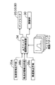
図1〜図15は本発明の一実施例を示すもので、図1は自動車の車室前部の斜視図、図2は図1の2−2線拡大断面図、図3は図2の3−3線断面図、図4は図2の4−4線拡大矢視図、図5は図4の5−5線断面図、図6は運転席用エアバッグ装置の分解斜視図、図7は図2の7−7線拡大断面図、図8は図7の8−8線断面図、図9は図8の9−9線拡大矢視図、図10は図9の10−10線断面図、図11は助手席用エアバッグ装置の分解斜視図、図12はベントホールの開度の制御系を示すブロック図、図13はベントホールの開度パターンの一例を示す図、図14は乗員の状態によるベントホールの開度パターンの変化を示す図、図15は車速によるベントホールの開度パターンの変化を示す図である。
【0016】
図1に示すように、運転席シート1の前方に配置されたステアリングホイール2の中央部に運転席用エアバッグ装置Rdが設けられ、また助手席シート3の前方に配置されたダッシュボード4の上部に助手席用エアバッグ装置Rpが設けられる。
【0017】
次に、図2〜図6に基づいて運転席用エアバッグ装置Rdの構造を説明する。
【0018】
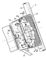
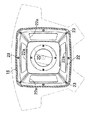
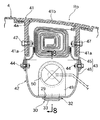
ステアリングホイール2は、ステアリングシャフト11の後端に相対回転不能に嵌合してナット12で固定されたステアリングボス13と、このステアリングボス13を囲むように配置された環状のホイールリム14と、前記ステアリングボス13に固定されたフロントカバー15と、このフロントカバー15に結合されたリヤカバー16と、前記フロントカバー15をホイールリム14に接続する複数本のスポーク17…とを備えており、フロントカバー15およびリヤカバー16により区画される空間にエアバッグモジュール18が収納される。
【0019】
エアバッグモジュール18は、それをリヤカバー16の内部に支持するためのリテーナ19と、高圧ガスを発生するインフレータ20と、インフレータ20が発生した高圧ガスにより膨張するエアバッグ21とから構成される。四角い板状のリテーナ19の外周部と、中央にインフレータ20を支持するブラケット22の外周部と、エアバッグ21の開口部周縁とが重ね合わされ、リヤカバー16の内周に一体に形成された取付フランジ16aに複数本のボルト23…で共締めされる。インフレータ20のガス噴出口20a…はエアバッグ21の内部空間に開放しており、またエアバッグ21の内部空間はブラケット22に形成した4個の通孔22a…を介して、ブラケット22およびリテーナ19に挟まれた空間に連通する。
【0020】
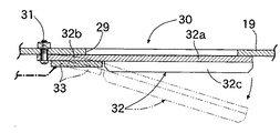
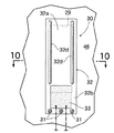
ブラケット22に臨むリテーナ19に長方形のベントホール29が形成される。ベントホール29の開度を制御する制御弁30は、短冊状に形成されて長手方向一端がボルト31…でリテーナ19の外表面に固定された弁体32を備える。弁体32はベントホール29を覆う本体部32aと、該本体部32aの前記ボルト31…に近い位置に設けられたヒンジ部32bとから構成される。弁体32の本体部32aの剛性を高めるべく、その幅方向の両側縁が折り曲げられて、弁体32の長手方向に各々延びる一対のフランジ32c,32cが形成される。また弁体32をヒンジ部32bにおいて屈曲させるべく、該ヒンジ部32bの背面にアクチュエータとしての四角形の圧電素子33が接着される。
【0021】
図12に示すように、エアバッグ展開制御装置34には、車両の衝突時の加速度を検出する加速度検出手段35aと、乗員の体重、体格、着座姿勢等の乗員状態を検出する乗員状態検出手段35bと、車速を検出する車速検出手段35cとが接続される。乗員状態検出手段35bは、シートクッションに設けられて乗員の体重を検出することにより大人および子供を識別するもの、あるいは赤外線で乗員の座高を検出することにより大人および子供を識別するものから構成される。
【0022】
エアバッグ展開制御装置34は、車両の衝突時に所定値以上の加速度が検出されるとインフレータ20を点火し、インフレータ20が発生するガスで膨張するエアバッグ21はリヤカバー16にH形に形成された薄肉のティアライン16b(図6参照)を破断して車室内に展開する。このとき、エアバッグ展開制御装置34は乗員状態検出手段35bあるいは車速検出手段35cからの信号に基づいて制御弁30の圧電素子33に対する通電を制御し、ベントホール29の開度を変化させる。
【0023】
即ち、圧電素子33への非通電時には、図5に実線で示すように制御弁30の弁体32のヒンジ部32bは直線状に延びており、ヒンジ部32bに連なる本体部32aはベントホール29を閉塞している。この状態から圧電素子33に通電すると、図5に鎖線で示すように通電量に応じて圧電素子33が収縮するため、弁体32のヒンジ部32bが湾曲して本体部32aがベントホール29を開放する。
【0024】
このように、ベントホール29を覆う弁体32に設けた圧電素子33に通電して湾曲させるだけの極めて簡単な構造により、ベントホール29の開度を精密にかつ無段階に制御することができる。しかも圧電素子33は制御弁30の弁体32のヒンジ部32bだけに設けられているため、その圧電素子33を弁体32の本体部32aの全面に設ける場合に比べて、高価な圧電素子33の使用量を減少させてコストダウンに寄与することができるだけでなく、圧電素子33の僅かな動きを拡大して弁体32に伝達することができる。また弁体32の本体部32aの剛性をフランジ32c,32cで高めているので、本体部32aをリテーナ19に密着させてベントホール29を確実に閉塞することができる。
【0025】
また弁体32はリテーナ19の外表面(インフレータ20が臨む面と反対側の面)からベントホール29を覆っているので、インフレータ20が高圧ガスを発生したときに圧電素子33の作動不足や不作動により弁体32が充分に開放しなくても、リテーナ19の内部のガス圧の増加により弁体32を外側に強制的に開放することができ、これによりエアバッグ21の内圧が過剰に高まるのを防止することができる。
【0026】
尚、ベントホール29の複数の開度パターン、つまり時間の経過に対するベントホール29の開度変化が予めマップとして記憶されており、エアバッグ展開制御装置34は前記複数の開度パターンのうちから所定の開度パターンを選択して制御弁30を制御する。この制御弁30の開度制御の具体的内容は後から詳述する。
【0027】
次に、図7〜図11に基づいて助手席用エアバッグ装置Rpの構造を説明する。
【0028】
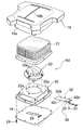
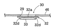
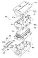
ダッシュボード4の上面に形成された開口4aに固定されたリッド41から下方に延びる支持部41a…に、エアバッグモジュール42のリテーナ43が固定される。リテーナ43は複数本のボルト44…で固定されたアッパーリテーナ45およびロアリテーナ46から構成されており、アッパーリテーナ44が複数本のボルト47…で前記リッド41の支持部41a…に固定される。アッパーリテーナ45およびロアリテーナ46の結合部にエアバッグ48の開口部周縁が挟まれて前記ボルト47…で共締めされる。リッド41には、エアバッグ48が膨張する際に破断する薄肉のティアライン41bが形成される。ロアリテーナ46の底部に一対の取付ブラケット49,49を介して円筒状のインフレータ50が支持される。
【0029】
またロアリテーナ46の底部に形成された長方形のベントホール29を開閉する制御弁30は、前記運転席用エアバッグ装置Rdのものと実質的に同じ構造を備えており、弁体32のヒンジ部32bに設けた圧電素子33への通電により該ヒンジ部32bを屈曲させ、本体部32aをベントホール29から離反させるようになっている。但し、運転席用エアバッグ装置Rdの制御弁30の弁体32は、フランジ32c,32cによって本体部32aに剛性を与えているのに対し、助手席用エアバッグ装置Rpの制御弁30の弁体32は、ビード32d,32dによって本体部32aに剛性を与えている点が相違しており、その他の構造および作用は同じである。
【0030】
加速度検出手段35a、乗員状態検出手段35bおよび車速検出手段35cからの信号が入力されるエアバッグ展開制御装置34により、インフレータ50および制御弁30に対する通電が制御される。即ち、車両の衝突時に加速度検出手段35aが所定値以上の加速度を検出すると、エアバッグ展開制御装置34からの指令でインフレータ50が点火して高圧ガスが発生し、その圧力で膨張するエアバッグ48はリッド41のティアライン41bを破断して車室内に展開する。このとき、乗員状態検出手段35bおよび車速検出手段35cからの信号によって制御弁30の開度が制御される。
【0031】
次に、運転席用エアバッグ装置Rdおよび助手席用エアバッグ装置Rpのベントホール29の開閉制御の内容を、図13〜図15を参照して具体的に説明する。
【0032】
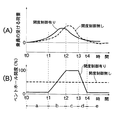
図13(A)の横軸はエアバッグ21,48が展開を完了してからの時間を示し、縦軸は乗員がエアバッグ21,48から受ける荷重の大きさを示している。また図13(B)の横軸は同じくエアバッグ21,48が展開を完了してからの時間を示し、縦軸はベントホール29の開度(全開状態を100%としたもの)を示している。ここで破線はエアバッグ21,48に一定面積のベントホールを設けた従来のものに対応し、実線はリテーナ19に形成したベントホール29の開度を制御弁30で制御する本実施例に対応する。
【0033】
同図から明らかなように、本実施例では、時刻t0〜t1の領域aでベントホール29の開度を小さく抑えてエアバッグ21,48からガスが排出され難くすることにより、衝突の慣性で前進する乗員がエアバッグ21,48を押し始める初期の拘束荷重を高めている。続く時刻t1〜t2の領域bでベントホール29の開度を増加させ、時刻t2〜t3の領域cでベントホール29の開度を大きな値に保持することにより、乗員がエアバッグ21,48から受ける拘束荷重の最大値を低減して乗員を柔らかく拘束している。続く時刻t3〜t4の領域dでベントホール29の開度を減少させ、時刻t4〜の領域eでベントホール29の開度を小さく抑えてエアバッグ21,48からガスが排出され難くすることにより、エアバッグ21,48が早期に収縮するのを防止して乗員がステアリングホイール2やダッシュボード4に二次衝突する衝撃を充分に緩和している。
【0034】
このように、ベントホール29の開度を予め設定した開度パターンに応じて制御するので、乗員がエアバッグ21,48から受ける荷重の特性を任意に制御して理想の特性に近づけることができる。
【0035】
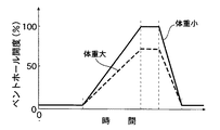
上記ベントホール29の開度パターンは、乗員状態検出手段35bの検出結果に応じて変更される。即ち、図14に示すように、乗員の体重が小さい場合には前記領域cにおけるベントホール29の全開開度が100%に設定されるが、乗員の体重が大きい場合にはその体重が増加するのに応じて全開開度が100%から例えば70%まで漸減される。その理由は、乗員の体重が大きい場合にベントホール29の全開開度が大き過ぎると、乗員がエアバッグ21,48を圧縮する荷重でベントホール29から排出されるガス量が多くなり過ぎ、エアバッグ21,48を膨張状態に維持できなくなる可能性があるためである。
【0036】
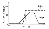
上記ベントホール29の開度パターンは、車速検出手段35cの検出結果に応じて変更される。即ち、図15に示すように、衝突時の車速が小さい場合には必要な拘束力も小さくなるため、ベントホール29の全開開度が大きく設定され、かつその全開開度が最後まで維持される。これにより、乗員がエアバッグ21,48から受ける拘束荷重の最大値を低減して乗員を一層柔らかく拘束することができる。
【0037】
以上、本発明の実施例を詳述したが、本発明はその要旨を逸脱しない範囲で種々の設計変更を行うことが可能である。
【0038】
例えば、ベントホール29の形状、制御弁30の弁体32の形状、圧電素子33の形状は、実施例に限定されず適宜変更可能である。
【0039】
【発明の効果】
以上のように請求項1,2にそれぞれ記載された各発明によれば、インフレータが発生する高圧ガスでエアバッグを展開させる際に、高圧ガスを逃がすベントホールの開度を制御弁で制御することにより、エアバッグの展開速度、エアバッグの拘束力の大きさ、エアバッグの収縮速度等を衝突の状態や乗員の状態に応じて任意に設定することができる。またベントホールを覆う短冊状弁体のヒンジ部に接着した圧電素子に通電して該ヒンジ部を湾曲させるだけの極めて簡単な構造により、ベントホールの開度を精密にかつ無段階に制御することができ、しかも圧電素子は弁体のヒンジ部だけに設けられているため、高価な圧電素子の使用量を減少させてコストダウンに寄与することができるだけでなく、圧電素子の僅かな動きを拡大して弁体に伝達することで弁体を大きく作動させることができ、アクチュエータ(圧電素子)を大幅に小型化してコストダウンを図ることができる。さらに弁体の本体部の剛性を、幅方向両側縁のフランジ部で高めているので、本体部をリテーナに密着させてベントホールを確実に閉塞することができる。
【0041】
また請求項3に記載された発明によれば、制御弁の弁体が内部にインフレータを収納するリテーナの外側からベントホールを覆っているので、アクチュエータの作動不足や不作動により制御弁が充分に開放しない場合であっても、リテーナの内圧の増加により制御弁を強制的に開放してエアバッグの内圧が過剰に高まるのを防止することができる。
【図面の簡単な説明】
【図1】自動車の車室前部の斜視図
【図2】図1の2−2線拡大断面図
【図3】図2の3−3線断面図
【図4】図2の4−4線拡大矢視図
【図5】図4の5−5線断面図
【図6】運転席用エアバッグ装置の分解斜視図
【図7】図2の7−7線拡大断面図
【図8】図7の8−8線断面図
【図9】図8の9−9線拡大矢視図
【図10】図9の10−10線断面図
【図11】助手席用エアバッグ装置の分解斜視図
【図12】ベントホールの開度の制御系を示すブロック図
【図13】ベントホールの開度パターンの一例を示す図
【図14】乗員の状態によるベントホールの開度パターンの変化を示す図
【図15】車速によるベントホールの開度パターンの変化を示す図
【符号の説明】
19 リテーナ
20 インフレータ
21 エアバッグ
29 ベントホール
30 制御弁
32 弁体
32a 本体部
32b ヒンジ部
32c フランジ部
32d ビード部
33 圧電素子
43 リテーナ
48 エアバッグ
50 インフレータ[0001]
BACKGROUND OF THE INVENTION
The present invention relates to an airbag apparatus in which an inflator is housed in a retainer to which a periphery of an opening portion of a folded airbag is fixed, and the airbag is deployed with gas generated by the inflator when a vehicle collides to restrain an occupant. Further, the present invention relates to an apparatus having a control valve capable of opening and closing a vent hole formed in the retainer.
[0002]
[Prior art]
In a conventional airbag device, a vent hole is provided in an airbag that is inflated by a gas generated by an inflator, and a part of the gas is discharged from the vent hole to control the internal pressure of the airbag. In such an airbag device, by closing the vent hole with a thin film, the airbag is rapidly inflated at the initial stage of deployment, and when the deployment is completed and the internal pressure of the airbag increases, the thin film breaks, and the vent hole The one that exhausts gas from the vehicle and softly restrains the occupant has been proposed (see Japanese Utility Model Publication No. 5-6206).
[0003]
In addition, if two inflators are provided in the airbag device, and there is no occupant in the vicinity of the airbag device, both of the two inflators are ignited, and if there is an occupant in the vicinity of the airbag device, There has been proposed an apparatus in which only one inflator is ignited to control the deployment speed and the internal pressure of the airbag in accordance with the position of the occupant (see JP-A-9-301115).
[0004]
By the way, what is described in the above Japanese Utility Model Publication No. 5-6206 is likely to cause variations in the pressure at which the thin film breaks. Therefore, when the internal pressure of the airbag reaches a predetermined value, the vent hole is accurately opened. This is not only difficult, but also has a problem that precise control of the internal pressure is difficult because the vent hole once opened cannot be closed again. In addition, what is described in the above-mentioned Japanese Patent Application Laid-Open No. 9-301115 not only increases the number of parts due to the need for two inflators, but also increases the cost, as well as two levels of airbag deployment characteristics. There is a problem that fine control is difficult because it can only be controlled.
[0005]
Therefore, the present applicant has proposed that a vent hole is formed in a retainer that houses an inflator, and the vent hole is opened and closed by a control valve to finely control the deployment speed and internal pressure of the airbag (Japanese Patent Application). No. 10-143781).
[0006]
[Problems to be solved by the invention]
However, the one proposed in the above Japanese Patent Application No. 10-143781 is a control valve in which a piezoelectric element of the same shape is bonded to a protector made of a strip-shaped metal plate, and the protector together with the piezoelectric element by energizing the piezoelectric element. Is bent to open the vent hole, and there is a problem that an expensive piezoelectric element is increased in size and causes an increase in cost.
[0007]
The present invention has been made in view of the above circumstances, and aims to reduce the cost by reducing the size of an actuator of a control valve in an airbag apparatus having a control valve capable of opening and closing a vent hole formed in a retainer. And
[0008]
[Means for Solving the Problems]
In order to achieve the above object, according to the first aspect of the present invention, an inflator is housed in a retainer to which the periphery of the opening of a folded airbag is fixed, and the inflator is generated at the time of a vehicle collision. An airbag device that restrains an occupant by deploying an airbag with gas, comprising a control valve capable of opening and closing a vent hole formed in the retainer, wherein one end in a longitudinal direction of the control valve is the retainer A rectangular valve body that is fixed to the vent hole and a piezoelectric element that can drive the valve body, and the valve body includes a hinge portion that is connected to a fixed end to the retainer; A body portion longer than the hinge portion, which is connected to the opposite side to the fixed end of the hinge portion and covers the vent hole, and one side of the hinge portion opposite to the vent hole. Is being bonded said piezoelectric element is in, the piezoelectric element of the energized state, a said valve openable vent hole is bent at the hinge portion, in the width direction both side edges of the main body portion, a pair of flange portions each extending along a longitudinal direction of the valve body, the air bag device characterized by being formed to protrude from one surface of the opposite side is proposed with the vent hole of the main body portion, also claim According to the invention described in 2, the inflator is housed in the retainer to which the opening periphery of the folded airbag is fixed, and the airbag is deployed with the gas generated by the inflator at the time of the collision of the vehicle. A restraining airbag device comprising a control valve capable of opening and closing a vent hole formed in the retainer, wherein the control valve has one longitudinal end fixed to the retainer. The valve body is composed of a strip-shaped valve body that closes the vent hole and a piezoelectric element that can drive the valve body. The valve body includes a hinge portion that is connected to a fixed end of the valve body, and a hinge portion of the hinge portion. A main body portion that is longer than the hinge portion and covers the vent hole on the opposite side of the fixed end, and the piezoelectric element is bonded to one surface of the hinge portion on the opposite side to the vent hole. The valve element can be bent at the hinge portion by the energized piezoelectric element to open the vent hole, and extend along the longitudinal direction of the valve body at both side edges in the width direction of the main body portion. a pair of bead portions, the air bag device characterized by being formed to protrude from one surface of the opposite Ru been proposed with the vent hole of the body portion.
[0009]
According to the above configuration, when the airbag is deployed with the high-pressure gas generated by the inflator, the opening degree of the vent hole through which the high-pressure gas is released is controlled by the control valve. The size of the vehicle, the airbag contraction speed, and the like can be arbitrarily set according to the state of the collision and the state of the occupant. In addition , the opening degree of the vent hole can be precisely and continuously controlled by an extremely simple structure in which the piezoelectric element bonded to the hinge part of the strip-shaped valve body covering the vent hole is energized to bend the hinge part. In addition, since the piezoelectric element is provided only in the hinge part of the valve body, not only can the amount of expensive piezoelectric elements used be reduced, contributing to cost reduction, but also a slight movement of the piezoelectric elements can be expanded. By transmitting to the valve body, the valve body can be actuated greatly, and the actuator (piezoelectric element) can be greatly downsized to reduce the cost. Furthermore, since the rigidity of the main body portion of the valve body is enhanced by the flange portions on both side edges in the width direction, the vent hole can be reliably closed by bringing the main body portion into close contact with the retainer.
[0012]
According to the invention described in
[0013]
According to the above configuration, since the valve body of the control valve covers the vent hole from the outside of the retainer that houses the inflator, even if the control valve does not open sufficiently due to insufficient operation or non-operation of the actuator. By increasing the internal pressure of the retainer, the control valve can be forcibly opened to prevent the internal pressure of the airbag from increasing excessively.
[0014]
DETAILED DESCRIPTION OF THE INVENTION
Hereinafter, embodiments of the present invention will be described based on examples of the present invention shown in the accompanying drawings.
[0015]
1 to 15 show an embodiment of the present invention. FIG. 1 is a perspective view of a front portion of a passenger compartment of an automobile, FIG. 2 is an enlarged sectional view taken along line 2-2 of FIG. 1, and FIG. 4 is a sectional view taken along line 4-4 in FIG. 2, FIG. 5 is a sectional view taken along line 5-5 in FIG. 4, and FIG. 6 is an exploded perspective view of the driver airbag device. 7 is an enlarged sectional view taken along line 7-7 in FIG. 2, FIG. 8 is a sectional view taken along line 8-8 in FIG. 7, FIG. 9 is an enlarged view taken along line 9-9 in FIG. FIG. 11 is an exploded perspective view of the passenger airbag device, FIG. 12 is a block diagram showing a vent hole opening control system, and FIG. 13 shows an example of vent hole opening patterns. 14 is a diagram showing a change in the opening pattern of the vent hole depending on the state of the occupant, and FIG. 15 is a diagram showing a change in the opening pattern of the vent hole depending on the vehicle speed.
[0016]
As shown in FIG. 1, a driver seat airbag device Rd is provided at the center of a
[0017]
Next, the structure of the driver airbag device Rd will be described with reference to FIGS.
[0018]
The
[0019]
The
[0020]
A
[0021]
As shown in FIG. 12, the airbag
[0022]
The airbag
[0023]
That is, when the
[0024]
As described above, the opening degree of the
[0025]
Further, since the
[0026]
Note that a plurality of opening patterns of the
[0027]
Next, the structure of the passenger seat airbag device Rp will be described with reference to FIGS.
[0028]
A
[0029]
The
[0030]
Energization to the inflator 50 and the
[0031]
Next, the opening / closing control of the
[0032]
The horizontal axis in FIG. 13A indicates the time after the
[0033]
As is clear from the figure, in this embodiment, the opening of the
[0034]
Thus, since the opening degree of the
[0035]
The opening pattern of the
[0036]
The opening pattern of the
[0037]
As mentioned above, although the Example of this invention was explained in full detail, this invention can perform a various design change in the range which does not deviate from the summary.
[0038]
For example, the shape of the
[0039]
【The invention's effect】
According to the invention described respectively in
[0041]
According to the third aspect of the present invention, since the valve body of the control valve covers the vent hole from the outside of the retainer that houses the inflator, the control valve is not sufficiently operated due to insufficient or inoperative operation of the actuator. Even if it is not opened, it is possible to prevent the internal pressure of the airbag from excessively increasing by forcibly opening the control valve due to an increase in the internal pressure of the retainer.
[Brief description of the drawings]
1 is a perspective view of a front part of a passenger compartment of an automobile. FIG. 2 is an enlarged sectional view taken along line 2-2 in FIG. 1. FIG. 3 is a sectional view taken along line 3-3 in FIG. FIG. 5 is a sectional view taken along line 5-5 in FIG. 4. FIG. 6 is an exploded perspective view of the driver airbag device. FIG. 7 is an enlarged sectional view taken along line 7-7 in FIG. 7 is a cross-sectional view taken along line 8-8 in FIG. 7. FIG. 9 is an enlarged view taken along line 9-9 in FIG. 8. FIG. 10 is a cross-sectional view taken along line 10-10 in FIG. FIG. 12 is a block diagram showing a vent hole opening control system. FIG. 13 is a view showing an example of a vent hole opening pattern. FIG. 14 shows changes in the opening pattern of the vent hole depending on the occupant state. [Fig. 15] Diagram showing changes in vent hole opening pattern according to vehicle speed [Explanation of symbols]
19
32c flange
Claims (3)
前記制御弁(30)は、長手方向一端が前記リテーナ(19)に固定されて前記ベントホール(29)を閉塞する短冊状の弁体(32)と、この弁体(32)を駆動可能な圧電素子(33)とから構成され、
前記弁体(32)は、これの前記リテーナ(19)への固定端に連なるヒンジ部(32b)と、そのヒンジ部(32b)の前記固定端とは反対側に連なって前記ベントホール(29)を覆う、該ヒンジ部(32b)より長い本体部(32a)とを備え、
前記ヒンジ部(32b)の前記ベントホール(29)とは反対側の一面には前記圧電素子(33)が接着されていて、通電状態の該圧電素子(33)により、前記弁体(32)を該ヒンジ部(32b)で屈曲させてベントホール(29)を開放可能であり、
前記本体部(32a)の幅方向両側縁部には、弁体(32)の長手方向に沿って各々延びる一対のフランジ部(32c)が、該本体部(32a)の前記ベントホール(29)とは反対側の一面より突出して形成されることを特徴とするエアバッグ装置。 An inflator (2 0 ) is housed inside a retainer (1 9 ) to which the periphery of the opening of the folded airbag (2 1 ) is fixed, and the airbag is generated by gas generated by the inflator (2 0 ) when a vehicle collides. (2 1 ) an airbag device that restrains an occupant by deploying a control valve (30) that can open and close a vent hole (29) formed in the retainer (1 9 ).
The control valve (30) has a longitudinal end fixed to the retainer (19) and a strip-shaped valve body (32) that closes the vent hole (29), and can drive the valve body (32). A piezoelectric element (33) ,
The valve body (32) includes a hinge portion (32b) connected to a fixed end to the retainer (19) and a vent hole (29) connected to the opposite side of the hinge portion (32b) to the fixed end. And a main body part (32a) longer than the hinge part (32b),
The piezoelectric element (33) is bonded to one surface of the hinge portion (32b) opposite to the vent hole (29), and the valve element (32) is attached by the energized piezoelectric element (33 ). the is bent at the hinge portion (32 b) is capable of opening the vent hole (29),
A pair of flange portions (32c) extending along the longitudinal direction of the valve body (32) are provided at both side edges in the width direction of the main body portion (32a), and the vent hole (29) of the main body portion (32a). airbag equipment, characterized in that it is formed to protrude from one surface of the opposite side of the.
前記制御弁(30)は、長手方向一端が前記リテーナ(43)に固定されて前記ベントホール(29)を閉塞する短冊状の弁体(32)と、この弁体(32)を駆動可能な圧電素子(33)とから構成され、
前記弁体(32)は、これの前記リテーナ(43)への固定端に連なるヒンジ部(32b)と、そのヒンジ部(32b)の前記固定端とは反対側に連なって前記ベントホール(29)を覆う、該ヒンジ部(32b)より長い本体部(32a)とを備え、
前記ヒンジ部(32b)の前記ベントホール(29)とは反対側の一面には前記圧電素子(33)が接着されていて、通電状態の該圧電素子(33)により、前記弁体(32)を該ヒンジ部(32b)で屈曲させてベントホール(29)を開放可能であり、
前記本体部(32a)の幅方向両側縁部には、弁体(32)の長手方向に沿って各々延びる一対のビード部(32d)が、該本体部(32a)の前記ベントホール(29)とは反対側の一面より突出して形成されることを特徴とするエアバッグ装置。 Airbag gas opening portion of the folded air bag (4 8) is inside the housing a inflator (5 0) of the retainer (4 3) to be secured, the inflator upon collision of the vehicle (5 0) is generated an airbag apparatus for restraining an occupant by deploying (4 8), in which the with a retainer (4 3) open control valve formed vent hole (29) to (30),
The control valve (30) has a longitudinal end fixed to the retainer (43) and a strip-shaped valve body (32) that closes the vent hole (29), and can drive the valve body (32). A piezoelectric element (33) ,
The valve body (32) includes a hinge portion (32b) connected to a fixed end to the retainer (43) and a vent hole (29) connected to the opposite side of the fixed end of the hinge portion (32b). And a main body part (32a) longer than the hinge part (32b),
The piezoelectric element (33) is bonded to one surface of the hinge portion (32b) opposite to the vent hole (29), and the valve element (32) is attached by the energized piezoelectric element (33 ). the is bent at the hinge portion (32 b) is capable of opening the vent hole (29),
A pair of bead portions (32d) extending along the longitudinal direction of the valve body (32) are provided at both side edges in the width direction of the main body portion (32a), and the vent hole (29) of the main body portion (32a). airbags equipment, characterized in that it is formed to protrude from one surface of the opposite side of the.
Priority Applications (2)
| Application Number | Priority Date | Filing Date | Title |
|---|---|---|---|
| JP2000034340A JP4394792B2 (en) | 1999-11-22 | 2000-02-07 | Airbag device |
| US09/716,205 US6435549B1 (en) | 1999-11-22 | 2000-11-21 | Air bag device |
Applications Claiming Priority (3)
| Application Number | Priority Date | Filing Date | Title |
|---|---|---|---|
| JP11-330899 | 1999-11-22 | ||
| JP33089999 | 1999-11-22 | ||
| JP2000034340A JP4394792B2 (en) | 1999-11-22 | 2000-02-07 | Airbag device |
Publications (2)
| Publication Number | Publication Date |
|---|---|
| JP2001213265A JP2001213265A (en) | 2001-08-07 |
| JP4394792B2 true JP4394792B2 (en) | 2010-01-06 |
Family
ID=26573668
Family Applications (1)
| Application Number | Title | Priority Date | Filing Date |
|---|---|---|---|
| JP2000034340A Expired - Fee Related JP4394792B2 (en) | 1999-11-22 | 2000-02-07 | Airbag device |
Country Status (2)
| Country | Link |
|---|---|
| US (1) | US6435549B1 (en) |
| JP (1) | JP4394792B2 (en) |
Families Citing this family (19)
| Publication number | Priority date | Publication date | Assignee | Title |
|---|---|---|---|---|
| US6547274B2 (en) * | 2000-02-07 | 2003-04-15 | Honda Giken Kogyo Kabushiki Kaisha | Air bag device |
| JP4759867B2 (en) * | 2001-07-25 | 2011-08-31 | タカタ株式会社 | Airbag device |
| US6746044B2 (en) * | 2001-12-27 | 2004-06-08 | Trw Inc. | Actuatable fastener for air bag module vent |
| US6799777B2 (en) * | 2002-11-15 | 2004-10-05 | Delphi Technologies, Inc. | Apparatus and methods of venting gas in an airbag module |
| US7196459B2 (en) | 2003-12-05 | 2007-03-27 | International Resistive Co. Of Texas, L.P. | Light emitting assembly with heat dissipating support |
| DE102004009300A1 (en) * | 2004-02-26 | 2005-09-15 | Robert Bosch Gmbh | Occupant protection device |
| GB2413781B (en) * | 2004-05-05 | 2007-03-14 | Autoliv Dev | Improvements in or relating to an air-bag arrangement |
| US7232001B2 (en) | 2004-08-24 | 2007-06-19 | Sam Hakki | Collision air bag and flotation system |
| DE202004015166U1 (en) * | 2004-09-29 | 2005-02-10 | Trw Automotive Safety Systems Gmbh | Airbag module |
| DE202004018121U1 (en) * | 2004-11-22 | 2005-04-07 | Trw Automotive Safety Sys Gmbh | Vehicle steering wheel with gas bag module and discharge opening |
| DE202005005797U1 (en) * | 2005-04-12 | 2005-07-21 | Trw Automotive Safety Systems Gmbh | Airbag module with outflow device |
| JP2006306298A (en) * | 2005-04-28 | 2006-11-09 | Mazda Motor Corp | Vehicle occupant protection device |
| DE102006013359A1 (en) * | 2005-06-10 | 2006-12-14 | Takata-Petri Ag | Airbag module for a motor vehicle |
| EP1890915B1 (en) * | 2005-06-10 | 2008-10-08 | Takata-Petri AG | Airbag module |
| CN100554045C (en) * | 2005-07-20 | 2009-10-28 | 全兴创新科技股份有限公司 | Automobile safety air bag inflating device |
| EP1764272B1 (en) * | 2005-09-17 | 2008-05-21 | GSK INTEK CO., Ltd. | Inflating device for an air bag of a vehicle |
| US7431336B2 (en) * | 2005-10-17 | 2008-10-07 | Tk Holdings Inc. | Airbag module with inflation control |
| JP4899852B2 (en) * | 2006-12-18 | 2012-03-21 | 豊田合成株式会社 | Airbag device |
| US7874576B2 (en) * | 2009-04-16 | 2011-01-25 | Toyota Motor Engineering & Manufacturing North America, Inc. | Adjustable airbag systems for vehicles |
Family Cites Families (15)
| Publication number | Priority date | Publication date | Assignee | Title |
|---|---|---|---|---|
| JPH056206A (en) | 1991-06-27 | 1993-01-14 | Matsushita Electric Ind Co Ltd | Teaching playback sequencer |
| DE4133506A1 (en) * | 1991-10-10 | 1993-04-15 | Dynamit Nobel Ag | SAFETY DEVICE FOR PROTECTING A VEHICLE'S VEHICLE INJURY AGAINST IMPACT INJURIES |
| US5366241A (en) * | 1993-09-30 | 1994-11-22 | Kithil Philip W | Automobile air bag system |
| US5670853A (en) * | 1994-12-06 | 1997-09-23 | Trw Vehicle Safety Systems Inc. | Method and apparatus for controlling vehicle occupant position |
| US5695214A (en) * | 1996-02-06 | 1997-12-09 | Trw Vehicle Safety Systems Inc. | Air bag module with vent |
| US5820162A (en) * | 1996-03-21 | 1998-10-13 | Airbelt Systems, Llc. | Airbag system inflator |
| US5709405A (en) * | 1996-04-10 | 1998-01-20 | Morton International, Inc. | Variable mass flow airbag module |
| JP3617184B2 (en) * | 1996-05-15 | 2005-02-02 | タカタ株式会社 | Airbag occupant protection device |
| US5853192A (en) * | 1996-10-10 | 1998-12-29 | Alliedsignal Inc. | Variable vented housing |
| US5707078A (en) * | 1996-11-26 | 1998-01-13 | Takata, Inc. | Air bag module with adjustable cushion inflation |
| KR100192427B1 (en) * | 1996-12-19 | 1999-06-15 | 정몽규 | Air bag vent hole |
| US6039346A (en) * | 1997-01-17 | 2000-03-21 | General Motors Corporation | Air bag module with variable inflation |
| US5743558A (en) * | 1997-02-11 | 1998-04-28 | Takata, Inc. | Air cushion module with rotating vent ring |
| JP3566079B2 (en) | 1998-05-26 | 2004-09-15 | 本田技研工業株式会社 | Airbag device |
| US6241279B1 (en) * | 1998-05-26 | 2001-06-05 | Honda Giken Kogyo Kabushiki Kaisha | Air bag device |
-
2000
- 2000-02-07 JP JP2000034340A patent/JP4394792B2/en not_active Expired - Fee Related
- 2000-11-21 US US09/716,205 patent/US6435549B1/en not_active Expired - Lifetime
Also Published As
| Publication number | Publication date |
|---|---|
| US6435549B1 (en) | 2002-08-20 |
| JP2001213265A (en) | 2001-08-07 |
Similar Documents
| Publication | Publication Date | Title |
|---|---|---|
| JP4394792B2 (en) | Airbag device | |
| US6241279B1 (en) | Air bag device | |
| US6883831B2 (en) | Apparatus and method for controlling an inflatable cushion | |
| US5988674A (en) | Air bag apparatus | |
| JPH07329688A (en) | Vehicle airbag deployment method | |
| WO2012099636A1 (en) | Seat bolster chamber | |
| EP2132063B1 (en) | Airbag for protection of a vehicle occupant | |
| US7775554B2 (en) | Air bag module vent | |
| JP3646005B2 (en) | Airbag device | |
| JP3566080B2 (en) | Airbag device | |
| JP3660129B2 (en) | Airbag device | |
| JP3566081B2 (en) | Airbag device | |
| JP3566079B2 (en) | Airbag device | |
| JPH0790744B2 (en) | Airbag device for passenger protection | |
| JP2915380B2 (en) | Energy absorption structure on the side of the vehicle | |
| JP3566082B2 (en) | Airbag device | |
| JP4394810B2 (en) | Airbag device | |
| JP4394793B2 (en) | Airbag device | |
| JPH04221250A (en) | Air bag device | |
| JPH03281454A (en) | Air bag device for automobile | |
| JP4209727B2 (en) | Airbag device | |
| JP4781699B2 (en) | Airbag device for vehicle | |
| JP2001219804A (en) | Airbag device | |
| JPH0642925Y2 (en) | Airbag device for restraining passengers | |
| US20260125024A1 (en) | Tether protection panel for airbag module |
Legal Events
| Date | Code | Title | Description |
|---|---|---|---|
| A621 | Written request for application examination |
Free format text: JAPANESE INTERMEDIATE CODE: A621 Effective date: 20061201 |
|
| A977 | Report on retrieval |
Free format text: JAPANESE INTERMEDIATE CODE: A971007 Effective date: 20090219 |
|
| A131 | Notification of reasons for refusal |
Free format text: JAPANESE INTERMEDIATE CODE: A131 Effective date: 20090225 |
|
| A521 | Written amendment |
Free format text: JAPANESE INTERMEDIATE CODE: A523 Effective date: 20090413 |
|
| TRDD | Decision of grant or rejection written | ||
| A01 | Written decision to grant a patent or to grant a registration (utility model) |
Free format text: JAPANESE INTERMEDIATE CODE: A01 Effective date: 20091007 |
|
| A01 | Written decision to grant a patent or to grant a registration (utility model) |
Free format text: JAPANESE INTERMEDIATE CODE: A01 |
|
| A61 | First payment of annual fees (during grant procedure) |
Free format text: JAPANESE INTERMEDIATE CODE: A61 Effective date: 20091016 |
|
| R150 | Certificate of patent or registration of utility model |
Free format text: JAPANESE INTERMEDIATE CODE: R150 |
|
| FPAY | Renewal fee payment (event date is renewal date of database) |
Free format text: PAYMENT UNTIL: 20121023 Year of fee payment: 3 |
|
| FPAY | Renewal fee payment (event date is renewal date of database) |
Free format text: PAYMENT UNTIL: 20131023 Year of fee payment: 4 |
|
| LAPS | Cancellation because of no payment of annual fees |