EP1868839B1 - Power supply device, control method of power supply device, and motor vehicle equipped with power supply device - Google Patents
Power supply device, control method of power supply device, and motor vehicle equipped with power supply device Download PDFInfo
- Publication number
- EP1868839B1 EP1868839B1 EP06732169A EP06732169A EP1868839B1 EP 1868839 B1 EP1868839 B1 EP 1868839B1 EP 06732169 A EP06732169 A EP 06732169A EP 06732169 A EP06732169 A EP 06732169A EP 1868839 B1 EP1868839 B1 EP 1868839B1
- Authority
- EP
- European Patent Office
- Prior art keywords
- battery
- charge
- state
- voltage
- electric power
- Prior art date
- Legal status (The legal status is an assumption and is not a legal conclusion. Google has not performed a legal analysis and makes no representation as to the accuracy of the status listed.)
- Not-in-force
Links
Images

Classifications
-
- B—PERFORMING OPERATIONS; TRANSPORTING
- B60—VEHICLES IN GENERAL
- B60W—CONJOINT CONTROL OF VEHICLE SUB-UNITS OF DIFFERENT TYPE OR DIFFERENT FUNCTION; CONTROL SYSTEMS SPECIALLY ADAPTED FOR HYBRID VEHICLES; ROAD VEHICLE DRIVE CONTROL SYSTEMS FOR PURPOSES NOT RELATED TO THE CONTROL OF A PARTICULAR SUB-UNIT
- B60W20/00—Control systems specially adapted for hybrid vehicles
-
- B—PERFORMING OPERATIONS; TRANSPORTING
- B60—VEHICLES IN GENERAL
- B60K—ARRANGEMENT OR MOUNTING OF PROPULSION UNITS OR OF TRANSMISSIONS IN VEHICLES; ARRANGEMENT OR MOUNTING OF PLURAL DIVERSE PRIME-MOVERS IN VEHICLES; AUXILIARY DRIVES FOR VEHICLES; INSTRUMENTATION OR DASHBOARDS FOR VEHICLES; ARRANGEMENTS IN CONNECTION WITH COOLING, AIR INTAKE, GAS EXHAUST OR FUEL SUPPLY OF PROPULSION UNITS IN VEHICLES
- B60K6/00—Arrangement or mounting of plural diverse prime-movers for mutual or common propulsion, e.g. hybrid propulsion systems comprising electric motors and internal combustion engines
- B60K6/20—Arrangement or mounting of plural diverse prime-movers for mutual or common propulsion, e.g. hybrid propulsion systems comprising electric motors and internal combustion engines the prime-movers consisting of electric motors and internal combustion engines, e.g. HEVs
- B60K6/22—Arrangement or mounting of plural diverse prime-movers for mutual or common propulsion, e.g. hybrid propulsion systems comprising electric motors and internal combustion engines the prime-movers consisting of electric motors and internal combustion engines, e.g. HEVs characterised by apparatus, components or means specially adapted for HEVs
- B60K6/28—Arrangement or mounting of plural diverse prime-movers for mutual or common propulsion, e.g. hybrid propulsion systems comprising electric motors and internal combustion engines the prime-movers consisting of electric motors and internal combustion engines, e.g. HEVs characterised by apparatus, components or means specially adapted for HEVs characterised by the electric energy storing means, e.g. batteries or capacitors
-
- B—PERFORMING OPERATIONS; TRANSPORTING
- B60—VEHICLES IN GENERAL
- B60L—PROPULSION OF ELECTRICALLY-PROPELLED VEHICLES; SUPPLYING ELECTRIC POWER FOR AUXILIARY EQUIPMENT OF ELECTRICALLY-PROPELLED VEHICLES; ELECTRODYNAMIC BRAKE SYSTEMS FOR VEHICLES IN GENERAL; MAGNETIC SUSPENSION OR LEVITATION FOR VEHICLES; MONITORING OPERATING VARIABLES OF ELECTRICALLY-PROPELLED VEHICLES; ELECTRIC SAFETY DEVICES FOR ELECTRICALLY-PROPELLED VEHICLES
- B60L3/00—Electric devices on electrically-propelled vehicles for safety purposes; Monitoring operating variables, e.g. speed, deceleration or energy consumption
- B60L3/0023—Detecting, eliminating, remedying or compensating for drive train abnormalities, e.g. failures within the drive train
- B60L3/0046—Detecting, eliminating, remedying or compensating for drive train abnormalities, e.g. failures within the drive train relating to electric energy storage systems, e.g. batteries or capacitors
-
- B—PERFORMING OPERATIONS; TRANSPORTING
- B60—VEHICLES IN GENERAL
- B60L—PROPULSION OF ELECTRICALLY-PROPELLED VEHICLES; SUPPLYING ELECTRIC POWER FOR AUXILIARY EQUIPMENT OF ELECTRICALLY-PROPELLED VEHICLES; ELECTRODYNAMIC BRAKE SYSTEMS FOR VEHICLES IN GENERAL; MAGNETIC SUSPENSION OR LEVITATION FOR VEHICLES; MONITORING OPERATING VARIABLES OF ELECTRICALLY-PROPELLED VEHICLES; ELECTRIC SAFETY DEVICES FOR ELECTRICALLY-PROPELLED VEHICLES
- B60L3/00—Electric devices on electrically-propelled vehicles for safety purposes; Monitoring operating variables, e.g. speed, deceleration or energy consumption
- B60L3/0092—Electric devices on electrically-propelled vehicles for safety purposes; Monitoring operating variables, e.g. speed, deceleration or energy consumption with use of redundant elements for safety purposes
-
- B—PERFORMING OPERATIONS; TRANSPORTING
- B60—VEHICLES IN GENERAL
- B60L—PROPULSION OF ELECTRICALLY-PROPELLED VEHICLES; SUPPLYING ELECTRIC POWER FOR AUXILIARY EQUIPMENT OF ELECTRICALLY-PROPELLED VEHICLES; ELECTRODYNAMIC BRAKE SYSTEMS FOR VEHICLES IN GENERAL; MAGNETIC SUSPENSION OR LEVITATION FOR VEHICLES; MONITORING OPERATING VARIABLES OF ELECTRICALLY-PROPELLED VEHICLES; ELECTRIC SAFETY DEVICES FOR ELECTRICALLY-PROPELLED VEHICLES
- B60L50/00—Electric propulsion with power supplied within the vehicle
- B60L50/10—Electric propulsion with power supplied within the vehicle using propulsion power supplied by engine-driven generators, e.g. generators driven by combustion engines
- B60L50/16—Electric propulsion with power supplied within the vehicle using propulsion power supplied by engine-driven generators, e.g. generators driven by combustion engines with provision for separate direct mechanical propulsion
-
- B—PERFORMING OPERATIONS; TRANSPORTING
- B60—VEHICLES IN GENERAL
- B60L—PROPULSION OF ELECTRICALLY-PROPELLED VEHICLES; SUPPLYING ELECTRIC POWER FOR AUXILIARY EQUIPMENT OF ELECTRICALLY-PROPELLED VEHICLES; ELECTRODYNAMIC BRAKE SYSTEMS FOR VEHICLES IN GENERAL; MAGNETIC SUSPENSION OR LEVITATION FOR VEHICLES; MONITORING OPERATING VARIABLES OF ELECTRICALLY-PROPELLED VEHICLES; ELECTRIC SAFETY DEVICES FOR ELECTRICALLY-PROPELLED VEHICLES
- B60L58/00—Methods or circuit arrangements for monitoring or controlling batteries or fuel cells, specially adapted for electric vehicles
- B60L58/10—Methods or circuit arrangements for monitoring or controlling batteries or fuel cells, specially adapted for electric vehicles for monitoring or controlling batteries
- B60L58/12—Methods or circuit arrangements for monitoring or controlling batteries or fuel cells, specially adapted for electric vehicles for monitoring or controlling batteries responding to state of charge [SoC]
-
- B—PERFORMING OPERATIONS; TRANSPORTING
- B60—VEHICLES IN GENERAL
- B60L—PROPULSION OF ELECTRICALLY-PROPELLED VEHICLES; SUPPLYING ELECTRIC POWER FOR AUXILIARY EQUIPMENT OF ELECTRICALLY-PROPELLED VEHICLES; ELECTRODYNAMIC BRAKE SYSTEMS FOR VEHICLES IN GENERAL; MAGNETIC SUSPENSION OR LEVITATION FOR VEHICLES; MONITORING OPERATING VARIABLES OF ELECTRICALLY-PROPELLED VEHICLES; ELECTRIC SAFETY DEVICES FOR ELECTRICALLY-PROPELLED VEHICLES
- B60L58/00—Methods or circuit arrangements for monitoring or controlling batteries or fuel cells, specially adapted for electric vehicles
- B60L58/10—Methods or circuit arrangements for monitoring or controlling batteries or fuel cells, specially adapted for electric vehicles for monitoring or controlling batteries
- B60L58/18—Methods or circuit arrangements for monitoring or controlling batteries or fuel cells, specially adapted for electric vehicles for monitoring or controlling batteries of two or more battery modules
- B60L58/20—Methods or circuit arrangements for monitoring or controlling batteries or fuel cells, specially adapted for electric vehicles for monitoring or controlling batteries of two or more battery modules having different nominal voltages
-
- B—PERFORMING OPERATIONS; TRANSPORTING
- B60—VEHICLES IN GENERAL
- B60W—CONJOINT CONTROL OF VEHICLE SUB-UNITS OF DIFFERENT TYPE OR DIFFERENT FUNCTION; CONTROL SYSTEMS SPECIALLY ADAPTED FOR HYBRID VEHICLES; ROAD VEHICLE DRIVE CONTROL SYSTEMS FOR PURPOSES NOT RELATED TO THE CONTROL OF A PARTICULAR SUB-UNIT
- B60W10/00—Conjoint control of vehicle sub-units of different type or different function
- B60W10/04—Conjoint control of vehicle sub-units of different type or different function including control of propulsion units
- B60W10/08—Conjoint control of vehicle sub-units of different type or different function including control of propulsion units including control of electric propulsion units, e.g. motors or generators
-
- B—PERFORMING OPERATIONS; TRANSPORTING
- B60—VEHICLES IN GENERAL
- B60W—CONJOINT CONTROL OF VEHICLE SUB-UNITS OF DIFFERENT TYPE OR DIFFERENT FUNCTION; CONTROL SYSTEMS SPECIALLY ADAPTED FOR HYBRID VEHICLES; ROAD VEHICLE DRIVE CONTROL SYSTEMS FOR PURPOSES NOT RELATED TO THE CONTROL OF A PARTICULAR SUB-UNIT
- B60W10/00—Conjoint control of vehicle sub-units of different type or different function
- B60W10/24—Conjoint control of vehicle sub-units of different type or different function including control of energy storage means
- B60W10/26—Conjoint control of vehicle sub-units of different type or different function including control of energy storage means for electrical energy, e.g. batteries or capacitors
-
- H—ELECTRICITY
- H02—GENERATION; CONVERSION OR DISTRIBUTION OF ELECTRIC POWER
- H02J—CIRCUIT ARRANGEMENTS OR SYSTEMS FOR SUPPLYING OR DISTRIBUTING ELECTRIC POWER; SYSTEMS FOR STORING ELECTRIC ENERGY
- H02J7/00—Circuit arrangements for charging or depolarising batteries or for supplying loads from batteries
- H02J7/0069—Charging or discharging for charge maintenance, battery initiation or rejuvenation
-
- B—PERFORMING OPERATIONS; TRANSPORTING
- B60—VEHICLES IN GENERAL
- B60W—CONJOINT CONTROL OF VEHICLE SUB-UNITS OF DIFFERENT TYPE OR DIFFERENT FUNCTION; CONTROL SYSTEMS SPECIALLY ADAPTED FOR HYBRID VEHICLES; ROAD VEHICLE DRIVE CONTROL SYSTEMS FOR PURPOSES NOT RELATED TO THE CONTROL OF A PARTICULAR SUB-UNIT
- B60W2510/00—Input parameters relating to a particular sub-units
- B60W2510/24—Energy storage means
- B60W2510/242—Energy storage means for electrical energy
- B60W2510/244—Charge state
-
- B—PERFORMING OPERATIONS; TRANSPORTING
- B60—VEHICLES IN GENERAL
- B60W—CONJOINT CONTROL OF VEHICLE SUB-UNITS OF DIFFERENT TYPE OR DIFFERENT FUNCTION; CONTROL SYSTEMS SPECIALLY ADAPTED FOR HYBRID VEHICLES; ROAD VEHICLE DRIVE CONTROL SYSTEMS FOR PURPOSES NOT RELATED TO THE CONTROL OF A PARTICULAR SUB-UNIT
- B60W2710/00—Output or target parameters relating to a particular sub-units
- B60W2710/24—Energy storage means
- B60W2710/242—Energy storage means for electrical energy
- B60W2710/244—Charge state
-
- B—PERFORMING OPERATIONS; TRANSPORTING
- B60—VEHICLES IN GENERAL
- B60Y—INDEXING SCHEME RELATING TO ASPECTS CROSS-CUTTING VEHICLE TECHNOLOGY
- B60Y2400/00—Special features of vehicle units
- B60Y2400/11—Electric energy storages
- B60Y2400/112—Batteries
-
- Y—GENERAL TAGGING OF NEW TECHNOLOGICAL DEVELOPMENTS; GENERAL TAGGING OF CROSS-SECTIONAL TECHNOLOGIES SPANNING OVER SEVERAL SECTIONS OF THE IPC; TECHNICAL SUBJECTS COVERED BY FORMER USPC CROSS-REFERENCE ART COLLECTIONS [XRACs] AND DIGESTS
- Y02—TECHNOLOGIES OR APPLICATIONS FOR MITIGATION OR ADAPTATION AGAINST CLIMATE CHANGE
- Y02T—CLIMATE CHANGE MITIGATION TECHNOLOGIES RELATED TO TRANSPORTATION
- Y02T10/00—Road transport of goods or passengers
- Y02T10/60—Other road transportation technologies with climate change mitigation effect
- Y02T10/70—Energy storage systems for electromobility, e.g. batteries
-
- Y—GENERAL TAGGING OF NEW TECHNOLOGICAL DEVELOPMENTS; GENERAL TAGGING OF CROSS-SECTIONAL TECHNOLOGIES SPANNING OVER SEVERAL SECTIONS OF THE IPC; TECHNICAL SUBJECTS COVERED BY FORMER USPC CROSS-REFERENCE ART COLLECTIONS [XRACs] AND DIGESTS
- Y02—TECHNOLOGIES OR APPLICATIONS FOR MITIGATION OR ADAPTATION AGAINST CLIMATE CHANGE
- Y02T—CLIMATE CHANGE MITIGATION TECHNOLOGIES RELATED TO TRANSPORTATION
- Y02T10/00—Road transport of goods or passengers
- Y02T10/60—Other road transportation technologies with climate change mitigation effect
- Y02T10/7072—Electromobility specific charging systems or methods for batteries, ultracapacitors, supercapacitors or double-layer capacitors
Definitions
- the present invention relates to a power supply device, a control method of the power supply device, and a motor vehicle equipped with the power supply device. More specifically the invention pertains to a power supply device that receives an external supply of electric power and supplies electric power to an external electric power-consuming apparatus, a control method of such a power supply device, and a motor vehicle equipped with such a power supply device.
- One proposed power supply device determines a voltage adjustment condition of plural cells, which are arranged in series to construct a battery assembly, according to the charge levels or the states of charge SOC of the respective cells, and actually adjusts the voltages of the respective cells in the battery assembly on the basis of the determined voltage adjustment condition (see, for example, Japanese Patent Laid-Open Gazette No. 2004-31012 ). Such voltage adjustment equalizes the voltages of the respective cells in the battery assembly.
- the aforementioned prior art power supply device does not include multiple batteries having different characteristics.
- the adjustment of the states of charge SOC of such multiple batteries may be undesirable under some conditions.
- Another background art is known from the European Patent Application No. EP 0 807 546 A1 , which discloses an electric vehicle power supply. According thereto, to obtain an electric vehicle power supply having a high output power density and regenerative power density, there are used a first battery whose regenerative power density increases with decrease of the SOC and a second battery whose output power density increases with increase of the SOC. And a control is performed so that the SOC of the first battery is maintained low while the SOC of the second battery is maintained high.
- a vehicle power supply for a hybridpowered electric automobile which is adapted to feed power to a motor-generator or regenerate power therefrom, wherein the motor-generator is caused to serve to produce vehicle-driving power.
- the vehicle power supply includes two power supplies, and a margin of regeneration is always kept so that full use can be made of the regenerative brake whenever the use of the brake is required.
- none of the aforementioned power supply devices provides a favorable adjustment of the state of charge of each battery and a favorable change or discharge of each battery according to the characteristics of the battery, as mentioned above.
- the object of the invention is to make the state of each battery have a favorable state of charge according to the characteristic of the battery.
- the control method of the power supply device, and the motor vehicle equipped with the power supply device the object of the invention is also to prevent quick deterioration of each battery.
- the control method of the power supply device, and the motor vehicle equipped with the power supply device the object of the invention is further to ensure exertion of good performance of each battery.
- a power supply device a control method of the power supply device, and a motor vehicle equipped with the power supply device of the invention having the configurations discussed below.
- the present invention is directed to a power supply device that receives an external supply of electric power and supplies electric power to an external electric power-consuming apparatus.
- the power supply device of the first aspect is defined in claim 1
- the power supply device of the invention adjusts the first voltage and the second voltage, based on the detected state of the first battery.
- the first voltage represents the voltage of the first voltage system connected with the first battery that is chargeable and dischargeable and has the first characteristic.
- the second voltage represents the voltage of the second voltage system connected with the second battery that is chargeable and dischargeable and has the second characteristic different from the first characteristic.
- the adjustment of the first voltage and the second voltage aims to cause transmission of electric power between the first battery and the second battery and make the first battery have the favorable state of charge. This arrangement of the invention enables the first battery to have the favorable state of charge.
- the first characteristic may be quick deterioration in a low state of charge having a low level of dischargeable electric power.
- the control module controls the voltage adjustment structure to shift the state of the first battery to a higher state of charge. This arrangement effectively prevents quick deterioration of the first battery.
- the first characteristic may be quick deterioration in a high state of charge having a high level of dischargeable electric power.
- the control module controls the voltage adjustment structure to shift the state of the first battery to a lower state of charge. This arrangement effectively prevents quick deterioration of the first battery.
- the first characteristic may be recovery of battery performance by a shift between a high state of charge having a high level of dischargeable electric power and a low state of charge having a low level of dischargeable electric power.
- the control module controls the voltage adjustment structure to recover the battery performance of the first battery. This arrangement ensures exertion of the good performance of the first battery. Further beneficial embodiments of the power supply device of the first aspect are defined in claim 2 and 3.
- the present invention is directed to a motor vehicle.
- the motor vehicle of the second aspect is defined in claim 4.
- the motor vehicle of the invention adjusts the first voltage and the second voltage, based on the detected state of the first battery.
- the first voltage represents the voltage of the first voltage system connected with the first battery that is chargeable and dischargeable and has the first characteristic.
- the second voltage represents the voltage of the second voltage system connected with the second battery that is chargeable and dischargeable and has the second characteristic different from the first characteristic.
- the adjustment of the first voltage and the second voltage aims to cause transmission of electric power between the first battery and the second battery and make the first battery have the favorable state of charge.
- This arrangement of the invention enables the first battery to have the favorable state of charge and ensures the adequate supply of electric power to a motor that outputs driving power for driving the motor vehicle.
- the present invention is directed to a control method of a power supply device, as defined in claim 5.
- the control method of the invention adjusts the first voltage and the second voltage, based on the detected state of the first battery.
- the first voltage represents the voltage of the first voltage system connected with the first battery that is chargeable and dischargeable and has the first characteristic.
- the second voltage represents the voltage of the second voltage system connected with the second battery that is chargeable and dischargeable and has the second characteristic different from the first characteristic.
- the adjustment of the first voltage and the second voltage aims to cause transmission of electric power between the first battery and the second battery and make the first battery have the favorable state of charge. This arrangement of the invention enables the first battery to have the favorable state of charge.
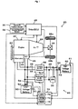
- Fig. 1 schematically illustrates the configuration of a motor vehicle 20 equipped with a power supply device 40 in one embodiment of the invention.
- the motor vehicle 20 of the embodiment includes an engine 22 that consumes gasoline as a fuel to output power, and an automatic transmission 24 that converts the output power of the engine 22 at one of multiple gear ratios and outputs the converted power to drive wheels 38a and 38b via a differential gear 36.
- the motor vehicle 20 of the embodiment also has a drive electronic control unit 28 (drive ECU 28) that controls the operations of the engine 22 and the automatic transmission 24, an alternator 33 that has a rotating shaft connected to a crankshaft of the engine 22 via a belt 23 and consumes the output power of the engine 22 to generate electric power, and the power supply device 40.
- drive ECU 28 drive electronice control unit 28
- alternator 33 that has a rotating shaft connected to a crankshaft of the engine 22 via a belt 23 and consumes the output power of the engine 22 to generate electric power
- the power supply device 40 the power supply device 40.
- the drive ECU 28 is constructed as a microcomputer including a CPU, an input port, and an output port, which are not specifically illustrated in Fig. 1 .
- the drive ECU 28 receives, via its input port, data required for controlling the operations of the engine 22 and the automatic transmission 24 from various sensors attached to the engine 22 and the automatic transmission 24.
- the input data include, for example, a gearshift position SP from a gearshift position sensor 30 and a vehicle speed from a vehicle speed sensor 32.
- the drive ECU 28 outputs, via its output port, diverse driving signals and control signals, for example, driving signals to a starter motor 26 for cranking the engine 22, driving signals to various actuators in the engine 22 and the automatic transmission 24, and driving signals to an electric power steering (EPS) 34.
- EPS electric power steering
- the power supply device 40 includes a low-voltage battery 50, a high-voltage battery 60, and a power supply electronic control unit 70 that controls the operations of the whole power supply device 40.
- the low-voltage battery 50 is connected with the alternator 33 via low-voltage power lines 46 to be charged with the electric power generated by the alternator 33 and supplies electric power to the starter motor 26 and other auxiliary machinery.
- the high-voltage battery 60 is connected with the low-voltage power lines 46 via a charging DC-DC converter 56 and via a discharging DC-DC converter 66.
- the low-voltage battery 50 and the high-voltage battery 60 are both secondary batteries but have different characteristics.
- the low-voltage battery 50 is, for example, a lead acid battery having a rated output voltage of 12V and quickly deteriorates in its state of charge SOC1 left at a low level.
- the high-voltage battery 60 is, for example, a lithium secondary battery having a rated output voltage of 36 V and quickly deteriorates in its state of charge SOC2 left at a high level.
- the lead acid battery used for the low-voltage battery 50 in the embodiment causes sulfation, on the other hand, when its state of charge SOC1 is kept at a high level. The sulfation represents accumulation of a sulfur compound on the surface of electrodes and worsens the battery performances.
- a discharging-charging cycle of the low-voltage battery 50 prevents such sulfation and ensures the good battery performances.
- the electric power steering (EPS) 34 is connected to the high-voltage power lines 48 linked to the high-voltage battery 60.
- the electric power steering (EPS) 34 accordingly receives a supply of electric power from the high-voltage system.
- the power supply electronic control unit 70 is constructed as a microcomputer including a CPU 72, a ROM 74 that stores processing programs, a RAM 76 that temporarily stores data, input and output ports (not shown), and a communication port (not shown).
- the power supply electronic control unit 70 receives, via its input port, diverse signals and data required for control; for example, an alternator temperature Ta from a temperature sensor (not shown) attached to the alternator 33, an alternator rotation speed Na from a rotation speed sensor (not shown) attached to the alternator 33, a low-voltage battery temperature Tb1 from a temperature sensor 51 attached to the low-voltage battery 50, a low-voltage battery voltage Vb1 from a voltage sensor 52 located between output terminals of the low-voltage battery 50, a low-voltage battery electric current Ib1 from an electric current sensor 54 located on the power line 46 in the vicinity of the output terminals of the low-voltage battery 50, a high-voltage battery temperature Tb2 from a temperature sensor 61 attached to the high-voltage
- the power supply electronic control unit 70 outputs, via its output port, driving signals to the alternator 33, control signals to the charging DC-DC converter 56, and control signals to the discharging DC-DC converter 66.
- the power supply electronic control unit 70 establishes communication with the drive ECU 28 to send and receive data to and from the drive ECU 28 according to the requirements.
- Fig. 2 is a flowchart showing a system-off control routine executed by the power supply electronic control unit 70 of the power supply device 40 at a system-off time.
- the CPU 72 of the power supply electronic control unit 70 first inputs the state of charge SOC1 of the low-voltage battery 50 and the state of charge SOC2 of the high-voltage battery 60 (step S100) .
- the state of charge SOC1 of the low-voltage battery 50 and the state of charge SOC2 of the high-voltage battery 60 are computed from accumulated values of the low-voltage battery electric current Ib1 measured by the electric current sensor 54 and the high-voltage battery electric current Ib2 measured by the electric current sensor 64 according to a charge reveal computation routine (not shown) and are stored in the RAM 76.
- the CPU 72 reads the computed state of charge SOC1 of the low-voltage battery 50 and the computed state of charge SOC2 of the high-voltage battery 60 from the storage of the RAM 76.
- the input state of charge SOC1 of the low-voltage battery 50 is compared with a discharging reference value Shi1 which is set to be lower than a full charge level (step S110).
- the input state of charge SOC2 of the high-voltage battery 60 is compared with a discharging preference value Slow2, which is set as a sufficient capacity for charging the low-voltage battery 50 (step S200).
- a discharging preference value Slow2 which is set as a sufficient capacity for charging the low-voltage battery 50.
- the CPU 72 specifies the current charge level of the high-voltage battery 60 as not sufficiently high for charging the low-voltage battery 50 and immediately exits from this system-off control routine without any further processing.
- the CPU 72 actuates and controls the discharging DC-DC converter 66 to have an output voltage Vout1 equal to a charging voltage Vset1 specified as an appropriate voltage level for fully charging the low-voltage battery 50 (step S210). This starts charging the low-voltage battery 50 with the electric power supplied from the high-voltage battery 60.
- step S220 After the start of charging the low-voltage battery 50, under condition of no system activation by an ignition-on operation (step S220), the processing of steps S230 and S240 is repeated until the state of charge SOC1 of the low-voltage battery 50 reaches a charge stop reference value Sfull, which is set as a value sufficiently close to a full charge level (step S250).
- the CPU 72 inputs the low-voltage battery electric current Ib1 from the electric current sensor 54, the high-voltage battery electric current Ib2 from the electric current sensor 64, the low-voltage battery voltage Vb1 from the voltage sensor 52, and the high-voltage battery voltage Vb2 from the voltage sensor 62 (step S230) and computes the state of charge SOC1 of the low-voltage battery 50 and the state of charge SOC2 of the high-voltage battery 60 from the input low-voltage battery electric current Ib1 and the input low-voltage battery voltage Vb1 and from the input high-voltage battery electric current Ib2 and the input high-voltage battery voltage Vb2 (step S240) .
- the CPU 72 stops the discharging DC-DC converter 66 (step S260) and exits from this system-off control routine.
- the low-voltage battery 50 is accordingly charged close to its full charge level.
- the lead acid battery used for the low-voltage battery 50 quickly deteriorates in the continuous low state of charge SOC1 as mentioned previously.
- Charging the low-voltage battery 50 close to its full charge level desirably prevents quick deterioration of the low-voltage battery 50.
- the high-voltage battery 60 is discharged to supply the electric power and charge the low-voltage battery 50.
- the state of charge SOC2 of the high-voltage battery 60 accordingly decreases from a sufficiently high charge level.
- the lithium secondary battery used for the high-voltage battery 60 quickly deteriorates in the continuous high state of charge SOC2.
- Discharging the high-voltage battery 60 from the sufficiently high charge level desirably prevents quick deterioration of the high-voltage battery 60.
- this control f low enables both the low-voltage battery 50 and the high-voltage battery 60 to have the respective favorable states of charge with little potentials for deterioration and effectively prevents quick deterioration of both the low-voltage battery 50 and the high-voltage battery 60.
- step S220 in the course of charging the low-voltage battery 50 before the state of charge SOC1 of the low-voltage battery 50 reaches the charge stop reference value Sfull (step S250)
- the CPU 72 immediately stops the discharging DC-DC converter 66 (step S260) and exits from the system-off control routine.
- the input state of charge SOC2 of the high-voltage battery 60 is compared with a charging reference value Shi2', which is set as a capacity to be sufficiently charged with discharge of the low-voltage battery 50 (step S120).
- a charging reference value Shi2' which is set as a capacity to be sufficiently charged with discharge of the low-voltage battery 50.
- the CPU 72 actuates and controls the charging DC-DC converter 56 to have an output voltage Vout2 equal to a charging voltage Vset2 specified as an appropriate voltage level for charging the high-voltage battery 60 (step S130). This starts charging the high-voltage battery 60 with the electric power supplied from the low-voltage battery 50.
- step S140 After the start of charging the high-voltage battery 60, under condition of no system activation by an ignition-on operation (step S140), the processing of steps S160 and S170 is repeated until the state of charge SOC1 of the low-voltage battery 50 decreases below a discharge stop reference value Slow1 which is set as a relatively small value (step S180).
- the CPU 72 inputs the low-voltage battery electric current Ib1 from the electric current sensor 54, the high-voltage battery electric current Ib2 from the electric current sensor 64, the low-voltage battery voltage Vb1 from the voltage sensor 52, and the high-voltage battery voltage Vb2 from the voltage sensor 62 (step S160) and computes the state of charge SOC1 of the low-voltage battery 50 and the state of charge SOC2 of the high-voltage battery 60 from the input low-voltage battery electric current Ib1 and the input low-voltage battery voltage Vb1 and from the input high-voltage battery electric current Ib2 and the input high-voltage battery voltage Vb2 (step S170) .
- the CPU 72 stops the charging DC-DC converter 56 (step S190) and executes the processing of and after step S200.
- the high-voltage battery 60 has been charred with the electric power supplied from the low-voltage battery 50 and the state of charge SOC2 of the high-voltage battery 60 reaches or exceeds the discharging reference value Sow2 at step S200.
- the low-voltage battery 50 is thus charged close to its full charge level with the electric power supplied from the high-voltage battery 60.
- the control flow discharges the low-voltage battery 50 and subsequently charges the low-voltage battery 50 close to its full charge level.
- the charging-discharging cycle of the low-voltage battery 50 effectively prevents the sulfation and ensues the good performances of the low-voltage battery 50.
- Such control is based on the characteristics of the lead acid battery used for the low-voltage battery 50. As mentioned previously, the lead acid battery continuously kept in the high state of change SOC causes accumulation of a sulfur compound on the surface of electrodes (sulfation) and worsens the battery performances.
- the discharging-charging cycle prevents such sulfation and ensures the good performances of the lead acid battery.
- the control flow executes the processing of steps S210 through S260 to charge the low-voltage battery 50 close to its full charge level. Namely this control flow enables both the low-voltage battery 50 and the high-voltage battery 60 to have the respective favorable states of charge with little potentials for deterioration and effectively prevents quick deterioration of both the low-voltage battery 50 and the high-voltage battery 60.
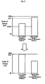
- Fig. 4 shows variations in state of charge SOC1 of the low-voltage battery 50 and in state of charge SOC2 of the high-voltage battery 60 by this control flow.
- step S140 In the event of system activation by an ignition-on operation (step S140) in the course of charging the high-voltage battery 60 before the state of charge SOC1 of the low-voltage battery 50 decreases below the discharge stop reference value Slowl (step S180), the CPU 72 immediately stops the charging DC-DC converter 56 (step S150) and exits from the system-off control routine.
- the low-voltage battery 50 when the state of charge SOC1 of the low-voltage battery 50 is lower than the discharging reference value Shil below the full charge level and when the statue of charge SOC2 of the high-voltage battery 60 is not lower than the discharging reference value Slow2 at the system-off time, the low-voltage battery 50 is charged close to its full charge level with the electric power supplied from the high-voltage battery 60.
- the lead acid battery used for the low-voltage battery 50 has the high potential for deterioration in the continuously low state of charge SOC.
- the lithium secondary battery used for the high-voltage battery 60 has the high potential for deterioration in the continuously high state of charge SOC.
- the charge of the low-voltage battery 50 in combination with the discharge of the high-voltage battery 60 enables both the low-voltage battery 50 and the high-voltage battery 60 to have the respective favorable states of charge with little potentials for deterioration. Namely the system-off control of the embodiment effectively prevents quick deterioration of both the low-voltage battery 50 and the high-voltage battery 60.
- the high-voltage battery 60 when the state of charge SOC1 of the low-voltage battery 50 is not lower than the discharging reference value Shi1 below the full charge level and when the state of charge SOC2 of the high-voltage battery 60 is lower than the charging reference value Shi2 at the system-off time, the high-voltage battery 60 is charged with the electric power supplied from the low-voltage battery 50. The charge of the high-voltage battery 60 is continued until the state of charge SOC1 of the low-voltage battery 50 decreases below the discharge stop reference value Slow1 The low-voltage battery 50 is then-charged-close to its full charge level with the electric power supplied from the high-voltage battery 60.
- This discharging-charging cycle effectively prevents the sulfation (accumulation of a sulfur compound on the surface of electrodes in the low-voltage battery 50 having the state of charge SOC1 continuously kept at the high level) and ensures the good performances of the low-voltage battery 50.
- the high-voltage battery 60 is charged with the electric power supplied from the low-voltage battery 50.
- the charge of the high-voltage battery 60 is continued until the state of charge SOC1 of the low-voltage battery 50 decreases below the discharge stop reference value Slow1.
- the low-voltage battery 50 is then charged close to its full charge level with the electric power supplied from the high-voltage battery 60.
- This discharging-charging cycle may not be required at every system-off time but may be performed at a rate of once per preset number of system-offs. The discharging-charging cycle may be omitted when not required.
- the power supply device 40 of the embodiment enables both the low-voltage battery 50 and the high-voltage battery 60 to have the respective favorable states of charge and prevents quick deterioration of both the low-voltage battery 50 and the high-voltage battery 60.
- One possible modification gives preference to the low-voltage battery 50 over the high-voltage battery 60 and preferentially makes the low-voltage battery 50 have the favorable state of charge to prevent quick deterioration of the low-voltage battery 50.
- Another possible modification gives preference to the high-voltage battery 60 over the low-voltage battery 50 and preferentially makes the high-voltage battery 60 have the favorable state of charge to prevent quick deterioration of the high-voltage battery 60. It is desirable to give preference to a battery having a greater degree of deterioration.
- the low-voltage battery 50 is charged by actuation of the discharging DC-DC converter 66, while being discharged by actuation of the charging DC-DC converter 56.
- the use of both the charging DC-DC converter 56 and the discharging DC-DC converter 66 is, however, not essential.
- the low-voltage battery 50 may be charged and discharged by actuation of only one DC-DC converter that enables simultaneous adjustment of both the voltage level on the low-voltage power lines 46 and the voltage level on the high-voltage power lines 48 and allows transmission of electric power between the low-voltage power lines 46 and the high-voltage power lines 48.
- the low-voltage power lines 46 are linked to the alternator 33 that receives the output power of the engine 22, generates electric power, and supplies the generated electric power to the power supply device 40.
- the alternator 33 may alternatively be linked to the high-voltage power lines 48.
- the power supply device 40 of the embodiment includes the lead acid battery and the lithium secondary battery as the multiple secondary batteries having different characteristics, that is, as the low-voltage battery 50 and the high-voltage battery 60.
- the secondary batteries having different characteristics are not restricted to the combination of the lead acid battery and the lithium secondary battery but may be any other suitable combination of multiple secondary batteries.
- the number of the multiple secondary batteries included in the power supply device of the invention is not limited to 2 but may be 3 or more. Any number of multiple secondary batteries are arranged to enable a shift in charge level of each secondary battery to its favorable state of charge through transmission of electric power between the multiple secondary batteries.
- the above embodiment regard the power supply device 40 mounted on the motor vehicle 20.
- the power supply device of the invention may be mounted on any of diverse moving bodies including automobiles, other vehicles, ships and boats, and aircraft or may be incorporated in any of diverse stationary systems including construction equipment.
- the technique of the invention may also be actualized by a control method of a power supply device that includes multiple secondary batteries having different characteristics.
- the technique of the present invention is preferably applicable to the manufacturing industries of power supply devices.
Landscapes
- Engineering & Computer Science (AREA)
- Transportation (AREA)
- Mechanical Engineering (AREA)
- Power Engineering (AREA)
- Sustainable Development (AREA)
- Sustainable Energy (AREA)
- Life Sciences & Earth Sciences (AREA)
- Chemical & Material Sciences (AREA)
- Combustion & Propulsion (AREA)
- Automation & Control Theory (AREA)
- Charge And Discharge Circuits For Batteries Or The Like (AREA)
- Electric Propulsion And Braking For Vehicles (AREA)
- Secondary Cells (AREA)
Applications Claiming Priority (2)
| Application Number | Priority Date | Filing Date | Title |
|---|---|---|---|
| JP2005118205A JP2006304393A (ja) | 2005-04-15 | 2005-04-15 | 電源装置およびその制御方法並びに車両 |
| PCT/JP2006/308361 WO2006112510A1 (en) | 2005-04-15 | 2006-04-14 | Power supply device, control method of power supply device, and motor vehicle equipped with power supply device |
Publications (2)
| Publication Number | Publication Date |
|---|---|
| EP1868839A1 EP1868839A1 (en) | 2007-12-26 |
| EP1868839B1 true EP1868839B1 (en) | 2010-12-29 |
Family
ID=36551893
Family Applications (1)
| Application Number | Title | Priority Date | Filing Date |
|---|---|---|---|
| EP06732169A Not-in-force EP1868839B1 (en) | 2005-04-15 | 2006-04-14 | Power supply device, control method of power supply device, and motor vehicle equipped with power supply device |
Country Status (6)
Cited By (1)
| Publication number | Priority date | Publication date | Assignee | Title |
|---|---|---|---|---|
| EP3951999B1 (en) * | 2020-04-10 | 2024-01-03 | Toyo System Co., Ltd. | Used battery unit depository |
Families Citing this family (76)
| Publication number | Priority date | Publication date | Assignee | Title |
|---|---|---|---|---|
| JP2008007003A (ja) * | 2006-06-30 | 2008-01-17 | Fuji Heavy Ind Ltd | ハイブリッド車両の制御装置 |
| JP4208006B2 (ja) | 2006-11-08 | 2009-01-14 | トヨタ自動車株式会社 | 電動車両 |
| JP4771928B2 (ja) * | 2006-12-06 | 2011-09-14 | 株式会社オートネットワーク技術研究所 | 電源装置 |
| JP2008275590A (ja) * | 2007-02-28 | 2008-11-13 | Stmicroelectronics Inc | パワーをモニタし且つ制御し且つ開負荷状態を検知する集積回路及び方法 |
| WO2008121982A1 (en) * | 2007-03-30 | 2008-10-09 | The Regents Of The University Of Michigan | Vehicle hybrid energy system |
| JP2009005450A (ja) * | 2007-06-20 | 2009-01-08 | Mazda Motor Corp | 車両用バッテリの制御装置 |
| US8098041B2 (en) * | 2007-11-04 | 2012-01-17 | GM Global Technology Operations LLC | Method of charging a powertrain |
| DE102008045101A1 (de) * | 2008-04-28 | 2009-11-05 | GM Global Technology Operations, Inc., Detroit | Doppelseitiges Wechselrichtersystem für ein Fahrzeug mit zwei Energiequellen, die unterschiedliche Betriebskennlinien aufweisen |
| US20100006351A1 (en) * | 2008-07-08 | 2010-01-14 | Howard J Scott | Electric vehicle with contra-recgarge system |
| JP5478870B2 (ja) * | 2008-10-15 | 2014-04-23 | 三菱重工業株式会社 | 蓄電システム及び電力貯蔵システム |
| JP4513917B2 (ja) * | 2008-11-13 | 2010-07-28 | トヨタ自動車株式会社 | 二次電池システム |
| JP5158217B2 (ja) * | 2009-06-18 | 2013-03-06 | トヨタ自動車株式会社 | 電池システム及び電池システム搭載車両 |
| DE102009028965A1 (de) * | 2009-08-28 | 2011-03-03 | Robert Bosch Gmbh | Schaltung zum Betreiben eines Hilfsaggregat für den Start von Verbrennungsmaschinen |
| CN101741126B (zh) * | 2009-12-07 | 2012-07-11 | 奇瑞汽车股份有限公司 | 防止汽车起动蓄电池过放电系统及其控制方法 |
| JP5409424B2 (ja) * | 2010-02-12 | 2014-02-05 | 富士重工業株式会社 | 電源装置 |
| US20120319650A1 (en) * | 2010-03-29 | 2012-12-20 | Toshiya Iwasaki | Recharging system |
| EP2596981B1 (en) | 2010-06-23 | 2019-05-22 | Toyota Jidosha Kabushiki Kaisha | Control device for vehicle and control method for vehicle |
| KR101583340B1 (ko) * | 2010-08-02 | 2016-01-21 | 엘지전자 주식회사 | 전기자동차의 배터리 제어장치 및 그 제어방법 |
| DE102010045501A1 (de) * | 2010-09-15 | 2012-03-15 | Audi Ag | Kraftwagen mit einer Hochspannungsquelle |
| EP2656319B1 (en) * | 2010-12-21 | 2021-03-17 | Volvo Lastvagnar AB | Method for controlling a power supply system of an automotive vehicle and power supply system adapted to such a method |
| WO2012084131A2 (de) * | 2010-12-23 | 2012-06-28 | Volkswagen Aktiengesellschaft | Verfahren und vorrichtung zum laden einer niedervoltbatterie in einem elektrischen antriebssystem |
| CN103329388B (zh) | 2011-02-03 | 2014-07-23 | 丰田自动车株式会社 | 二次电池的输出控制装置 |
| US8534400B2 (en) * | 2011-02-14 | 2013-09-17 | Ford Global Technologies, Llc | Electric vehicle and method of control for active auxiliary battery depletion |
| KR101229441B1 (ko) * | 2011-03-18 | 2013-02-06 | 주식회사 만도 | 배터리 충전 장치 |
| JP5609768B2 (ja) * | 2011-05-17 | 2014-10-22 | マツダ株式会社 | 車両の制御装置 |
| WO2013001620A1 (ja) * | 2011-06-29 | 2013-01-03 | トヨタ自動車株式会社 | 車両の電源システム |
| KR20130016875A (ko) * | 2011-08-09 | 2013-02-19 | 현대자동차주식회사 | 하이브리드 차량 |
| DE112011105562B4 (de) * | 2011-08-30 | 2024-11-21 | Toyota Jidosha Kabushiki Kaisha | Fahrzeug |
| JP5375917B2 (ja) * | 2011-09-29 | 2013-12-25 | コベルコクレーン株式会社 | 作業機械のバッテリ充放電制御装置 |
| KR101251243B1 (ko) * | 2011-10-27 | 2013-04-08 | 엘에스산전 주식회사 | 전기자동차의 전원 공급 시스템 |
| DE102011087678A1 (de) * | 2011-12-02 | 2013-06-06 | Conti Temic Microelectronic Gmbh | Vorrichtung zur Erfassung des Zustands eines zu prüfenden Akkumulators |
| US9365115B2 (en) * | 2012-01-20 | 2016-06-14 | Ford Global Technologies, Llc | System and method for vehicle power management |
| DE102012013413A1 (de) * | 2012-07-05 | 2014-01-09 | Li-Tec Battery Gmbh | Hybrider elektrochemischer Energiespeicher |
| JP5889750B2 (ja) * | 2012-08-10 | 2016-03-22 | 株式会社デンソー | 車両用電源システム |
| DE102012215755A1 (de) * | 2012-09-05 | 2014-03-06 | Robert Bosch Gmbh | Niedervoltnetz mit Gleichspannungswandler und Verfahren zum Testen einer Niedervoltbatterie |
| DE102012217190A1 (de) * | 2012-09-24 | 2014-06-12 | Bayerische Motoren Werke Aktiengesellschaft | Koppelspeichervorrichtung für ein Kraftfahrzeug |
| WO2014068896A1 (ja) * | 2012-10-29 | 2014-05-08 | 三洋電機株式会社 | 車載用電池システム |
| WO2014102892A1 (ja) * | 2012-12-25 | 2014-07-03 | トヨタ自動車株式会社 | 車両の電源システムおよびそれを備える車両ならびに車両の電源システムの制御方法 |
| US9680315B2 (en) * | 2012-12-27 | 2017-06-13 | Toyota Jidosha Kabushiki Kaisha | On-board control apparatus |
| GB2510821B (en) * | 2013-02-13 | 2015-08-19 | Jaguar Land Rover Ltd | Charging Method |
| US9584004B2 (en) * | 2013-03-13 | 2017-02-28 | Constructive Industries, Llc | Regenerative power supply system and method |
| JP5974946B2 (ja) * | 2013-03-21 | 2016-08-23 | 株式会社オートネットワーク技術研究所 | 電源装置 |
| CN103287281B (zh) * | 2013-05-21 | 2016-06-08 | 潍柴动力股份有限公司 | 一种汽车驱动系统及其电能控制方法 |
| DE102014201345A1 (de) * | 2014-01-27 | 2015-07-30 | Robert Bosch Gmbh | Bordnetz und Verfahren zum Betrieb eines Bordnetzes |
| US11112463B2 (en) * | 2014-04-11 | 2021-09-07 | Cps Technology Holdings Llc | Integrated battery sensor for multiple battery modules |
| KR102147321B1 (ko) * | 2014-04-16 | 2020-08-24 | 주식회사 만도 | 하이브리드 차량의 배터리 방전방지시스템 및 이를 이용한 배터리 방전방지방법 |
| WO2016035279A1 (ja) * | 2014-09-05 | 2016-03-10 | パナソニックIpマネジメント株式会社 | バッテリーシステム及び電動車両 |
| US9446680B2 (en) * | 2014-10-07 | 2016-09-20 | Ford Global Technologies, Llc | Method and apparatus for identifying battery pack types |
| KR101926896B1 (ko) * | 2014-11-20 | 2018-12-10 | 현대자동차주식회사 | 저전압 배터리 충전 제어방법 및 장치 |
| US9796277B2 (en) * | 2015-02-27 | 2017-10-24 | GM Global Technology Operations LLC | Electric bike extended range battery power electronics and control |
| US9647589B2 (en) * | 2015-06-22 | 2017-05-09 | Infineon Technologies Ag | Alternator with current measurement |
| CN106374549B (zh) * | 2015-07-23 | 2019-05-17 | 比亚迪股份有限公司 | 汽车电池的充电系统及汽车电池的充电方法及汽车 |
| US10173613B2 (en) * | 2015-08-18 | 2019-01-08 | GM Global Technology Operations LLC | System and method for monitoring a state of charge of a battery |
| CN108599553A (zh) * | 2015-08-25 | 2018-09-28 | 漳州龙文区汇洋远软件开发有限公司 | 一种电动车的电气系统 |
| CN105539180B (zh) * | 2015-12-28 | 2018-02-27 | 青岛大学 | 一种田字型电动汽车混合电源控制方法 |
| US10202043B2 (en) * | 2016-04-18 | 2019-02-12 | Ford Global Technologies, Llc | Structure to optimize electricity generation in a vehicle |
| GB2552483B (en) * | 2016-07-25 | 2020-04-22 | Jaguar Land Rover Ltd | Battery management apparatus and method |
| DE102016214484A1 (de) * | 2016-08-04 | 2018-02-08 | Audi Ag | Verfahren zum Vorbereiten einer Batterie eines Kraftfahrzeugs für einen Transport und Kraftfahrzeug |
| DE102016214995A1 (de) * | 2016-08-11 | 2018-02-15 | Robert Bosch Gmbh | System zur Batterieüberwachung für ein Fahrzeug |
| DE102016217955A1 (de) * | 2016-09-20 | 2018-03-22 | Voith Patent Gmbh | Verfahren zum Betreiben eines Hybridfahrzeugs |
| CN107919689B (zh) * | 2016-10-11 | 2020-02-07 | 比亚迪股份有限公司 | 电动汽车及其充电控制方法和系统 |
| KR101776763B1 (ko) * | 2016-11-11 | 2017-09-08 | 현대자동차 주식회사 | 마일드 하이브리드 차량의 저전압 배터리 충전 방법 및 장치 |
| JP2018186611A (ja) * | 2017-04-25 | 2018-11-22 | 株式会社オートネットワーク技術研究所 | 車載電力供給システム、車載制御装置及び電力供給制御方法 |
| JP6541713B2 (ja) * | 2017-04-28 | 2019-07-10 | 本田技研工業株式会社 | 車両の電源装置 |
| CN107264435B (zh) * | 2017-05-26 | 2019-06-28 | 天津中科华誉科技有限公司 | 用于新能源汽车低压蓄电池的智能维护方法 |
| US10439427B2 (en) * | 2017-08-03 | 2019-10-08 | Ford Global Technologies, Llc | Determining a fuel quantity to charge a vehicle battery |
| DE102017221825B4 (de) * | 2017-12-04 | 2019-06-27 | Audi Ag | Verfahren zum Steuern einer elektrischen Anlage eines elektrisch antreibbaren Kraftfahrzeugs |
| US10543757B2 (en) * | 2017-12-11 | 2020-01-28 | Fca Us Llc | Techniques for adjusting wakeup time of an electrified vehicle for low voltage battery conditioning |
| JP7109221B2 (ja) * | 2018-03-23 | 2022-07-29 | ダイヤゼブラ電機株式会社 | 電力変換装置 |
| JP7091830B2 (ja) | 2018-05-23 | 2022-06-28 | トヨタ自動車株式会社 | 電源装置 |
| JP7373113B2 (ja) * | 2019-05-28 | 2023-11-02 | マツダ株式会社 | 車両用電源制御装置 |
| JP6912125B1 (ja) * | 2020-07-13 | 2021-07-28 | 東洋システム株式会社 | 中古バッテリーユニット用保持具及び中古バッテリーユニット保管システム |
| HUE062267T2 (hu) * | 2020-12-30 | 2023-10-28 | Contemporary Amperex Technology Co Ltd | Akkumulátormodul kiegyenlítésére szolgáló eljárás és készülék, akkumulátormodul és teljesítménykezelõ vezérlõ |
| DE102021105170A1 (de) | 2021-03-03 | 2022-09-08 | Bayerische Motoren Werke Aktiengesellschaft | Hybridantrieb für ein Hybridelektrokraftfahrzeug |
| KR20220131446A (ko) * | 2021-03-19 | 2022-09-28 | 현대자동차주식회사 | 차량의 보조배터리 시스템 |
| CN117337526A (zh) * | 2021-05-28 | 2024-01-02 | 武汉路特斯汽车有限公司 | 车辆的充电控制方法、设备及计算机可读存储介质 |
Family Cites Families (17)
| Publication number | Priority date | Publication date | Assignee | Title |
|---|---|---|---|---|
| JPH06296302A (ja) * | 1993-02-15 | 1994-10-21 | Toyota Motor Corp | 電気自動車用エンジン駆動発電機の制御装置 |
| DE4437876A1 (de) * | 1993-10-30 | 1995-05-04 | Volkswagen Ag | Verfahren zum Betreiben der elektrischen Stromversorgung in einem Elektrofahrzeug |
| JPH08205312A (ja) | 1995-01-19 | 1996-08-09 | Nippondenso Co Ltd | シリーズハイブリッド車の制御方法及びその制御装置 |
| JP3617183B2 (ja) | 1996-05-08 | 2005-02-02 | トヨタ自動車株式会社 | 電気自動車の電源装置 |
| JP3711720B2 (ja) * | 1997-11-28 | 2005-11-02 | 株式会社デンソー | ハイブリッド電気自動車 |
| JP2002058175A (ja) * | 2000-08-07 | 2002-02-22 | Japan Storage Battery Co Ltd | 独立型電源システム |
| US20040201365A1 (en) * | 2001-04-05 | 2004-10-14 | Electrovaya Inc. | Energy storage device for loads having variable power rates |
| JP2002313412A (ja) | 2001-04-10 | 2002-10-25 | Matsushita Electric Ind Co Ltd | 二次電池の活性化方法 |
| TW521468B (en) * | 2001-06-14 | 2003-02-21 | Quanta Comp Inc | Charging apparatus capable of dynamically adjusting charging power |
| JP3706565B2 (ja) * | 2001-09-20 | 2005-10-12 | 三洋電機株式会社 | ハイブリッドカー用の電源装置 |
| WO2003041255A1 (en) * | 2001-11-02 | 2003-05-15 | Aker Wade Power Technologies Llc | Fast charger for high capacity batteries |
| JP3744414B2 (ja) * | 2001-11-29 | 2006-02-08 | トヨタ自動車株式会社 | 車両の制御装置 |
| JPWO2003055700A1 (ja) | 2001-12-26 | 2005-04-28 | 株式会社ブリヂストン | 空気入りタイヤ |
| JP2004031013A (ja) | 2002-06-24 | 2004-01-29 | Nissan Motor Co Ltd | 組電池の容量調整装置および方法 |
| JP3879598B2 (ja) | 2002-06-24 | 2007-02-14 | 日産自動車株式会社 | 組電池の容量調整装置および方法 |
| JP2004074907A (ja) * | 2002-08-16 | 2004-03-11 | Yamaha Motor Co Ltd | 電動車両用給電装置 |
| JP2004320872A (ja) | 2003-04-15 | 2004-11-11 | Isuzu Motors Ltd | 車両用電源装置 |
-
2005
- 2005-04-15 JP JP2005118205A patent/JP2006304393A/ja active Pending
-
2006
- 2006-04-14 DE DE602006019219T patent/DE602006019219D1/de active Active
- 2006-04-14 US US11/887,572 patent/US7839116B2/en not_active Expired - Fee Related
- 2006-04-14 EP EP06732169A patent/EP1868839B1/en not_active Not-in-force
- 2006-04-14 CN CN2006800125674A patent/CN101160688B/zh not_active Expired - Fee Related
- 2006-04-14 WO PCT/JP2006/308361 patent/WO2006112510A1/en active Application Filing
Cited By (1)
| Publication number | Priority date | Publication date | Assignee | Title |
|---|---|---|---|---|
| EP3951999B1 (en) * | 2020-04-10 | 2024-01-03 | Toyo System Co., Ltd. | Used battery unit depository |
Also Published As
| Publication number | Publication date |
|---|---|
| CN101160688B (zh) | 2010-05-19 |
| WO2006112510A1 (en) | 2006-10-26 |
| CN101160688A (zh) | 2008-04-09 |
| US20090015193A1 (en) | 2009-01-15 |
| JP2006304393A (ja) | 2006-11-02 |
| DE602006019219D1 (de) | 2011-02-10 |
| EP1868839A1 (en) | 2007-12-26 |
| US7839116B2 (en) | 2010-11-23 |
Similar Documents
| Publication | Publication Date | Title |
|---|---|---|
| EP1868839B1 (en) | Power supply device, control method of power supply device, and motor vehicle equipped with power supply device | |
| US20190054827A1 (en) | Dual function battery system and method | |
| JP5547699B2 (ja) | 車両の駆動装置 | |
| JP4026013B2 (ja) | トルク制御装置 | |
| US10059324B2 (en) | Travel driving apparatus of vehicle | |
| US11299140B2 (en) | Vehicle provided with generator | |
| JP4722976B2 (ja) | 蓄電容量制御装置 | |
| US20150046007A1 (en) | Electric power generation control system for hybrid automobile | |
| US20110037434A1 (en) | Method of controlling battery charge level of hybrid electric vehicle | |
| WO2005039919A1 (ja) | 二次電池の制御装置および制御方法 | |
| EP2675652B1 (en) | Vehicle and control method for vehicle | |
| JP5062041B2 (ja) | 蓄電手段制御装置および電気自動車 | |
| JP3906925B2 (ja) | トルク制御装置 | |
| JP2014004912A (ja) | ハイブリッド自動車の制御装置 | |
| JP2006304574A (ja) | 電源装置およびその制御方法 | |
| JP2013241129A (ja) | ハイブリッド自動車の発電制御装置 | |
| JP2011229287A (ja) | 駆動装置 | |
| JP3772875B2 (ja) | ハイブリッド車両の制御装置 | |
| JP7126531B2 (ja) | ハイブリッド車両の制御装置 | |
| JP3671446B2 (ja) | 車両用回生制動装置 | |
| JP5402838B2 (ja) | 電源装置および車両 | |
| JP2013216264A (ja) | ハイブリッド自動車の発電制御装置 |
Legal Events
| Date | Code | Title | Description |
|---|---|---|---|
| PUAI | Public reference made under article 153(3) epc to a published international application that has entered the european phase |
Free format text: ORIGINAL CODE: 0009012 |
|
| 17P | Request for examination filed |
Effective date: 20071010 |
|
| AK | Designated contracting states |
Kind code of ref document: A1 Designated state(s): DE FR |
|
| DAX | Request for extension of the european patent (deleted) | ||
| RBV | Designated contracting states (corrected) |
Designated state(s): DE FR |
|
| 17Q | First examination report despatched |
Effective date: 20080730 |
|
| GRAP | Despatch of communication of intention to grant a patent |
Free format text: ORIGINAL CODE: EPIDOSNIGR1 |
|
| RIN1 | Information on inventor provided before grant (corrected) |
Inventor name: OKABE, NOBUYUKI,C/O TOYOTA JIDOSHA K.K. Inventor name: KOMEDA, OSAMU,C/O TOYOTA JIDOSHA K.K. Inventor name: ESAKA, TOSHINORI,C/O TOYOTA JIDOSHA K.K. |
|
| GRAS | Grant fee paid |
Free format text: ORIGINAL CODE: EPIDOSNIGR3 |
|
| GRAA | (expected) grant |
Free format text: ORIGINAL CODE: 0009210 |
|
| AK | Designated contracting states |
Kind code of ref document: B1 Designated state(s): DE FR |
|
| REF | Corresponds to: |
Ref document number: 602006019219 Country of ref document: DE Date of ref document: 20110210 Kind code of ref document: P |
|
| REG | Reference to a national code |
Ref country code: DE Ref legal event code: R096 Ref document number: 602006019219 Country of ref document: DE Effective date: 20110210 |
|
| PLBE | No opposition filed within time limit |
Free format text: ORIGINAL CODE: 0009261 |
|
| STAA | Information on the status of an ep patent application or granted ep patent |
Free format text: STATUS: NO OPPOSITION FILED WITHIN TIME LIMIT |
|
| 26N | No opposition filed |
Effective date: 20110930 |
|
| REG | Reference to a national code |
Ref country code: DE Ref legal event code: R097 Ref document number: 602006019219 Country of ref document: DE Effective date: 20110930 |
|
| REG | Reference to a national code |
Ref country code: DE Ref legal event code: R084 Ref document number: 602006019219 Country of ref document: DE Effective date: 20130125 |
|
| PGFP | Annual fee paid to national office [announced via postgrant information from national office to epo] |
Ref country code: FR Payment date: 20140409 Year of fee payment: 9 Ref country code: DE Payment date: 20140430 Year of fee payment: 9 |
|
| REG | Reference to a national code |
Ref country code: DE Ref legal event code: R119 Ref document number: 602006019219 Country of ref document: DE |
|
| PG25 | Lapsed in a contracting state [announced via postgrant information from national office to epo] |
Ref country code: DE Free format text: LAPSE BECAUSE OF NON-PAYMENT OF DUE FEES Effective date: 20151103 |
|
| REG | Reference to a national code |
Ref country code: FR Ref legal event code: ST Effective date: 20151231 |
|
| PG25 | Lapsed in a contracting state [announced via postgrant information from national office to epo] |
Ref country code: FR Free format text: LAPSE BECAUSE OF NON-PAYMENT OF DUE FEES Effective date: 20150430 |