EP1868514B1 - Forceps and system using same - Google Patents
Forceps and system using same Download PDFInfo
- Publication number
- EP1868514B1 EP1868514B1 EP06750046A EP06750046A EP1868514B1 EP 1868514 B1 EP1868514 B1 EP 1868514B1 EP 06750046 A EP06750046 A EP 06750046A EP 06750046 A EP06750046 A EP 06750046A EP 1868514 B1 EP1868514 B1 EP 1868514B1
- Authority
- EP
- European Patent Office
- Prior art keywords
- pair
- forceps
- head portion
- forceps according
- elongated members
- Prior art date
- Legal status (The legal status is an assumption and is not a legal conclusion. Google has not performed a legal analysis and makes no representation as to the accuracy of the status listed.)
- Active
Links
Images

Classifications
-
- A—HUMAN NECESSITIES
- A61—MEDICAL OR VETERINARY SCIENCE; HYGIENE
- A61B—DIAGNOSIS; SURGERY; IDENTIFICATION
- A61B17/00—Surgical instruments, devices or methods
- A61B17/28—Surgical forceps
- A61B17/2812—Surgical forceps with a single pivotal connection
- A61B17/282—Jaws
-
- A—HUMAN NECESSITIES
- A61—MEDICAL OR VETERINARY SCIENCE; HYGIENE
- A61B—DIAGNOSIS; SURGERY; IDENTIFICATION
- A61B17/00—Surgical instruments, devices or methods
- A61B17/02—Surgical instruments, devices or methods for holding wounds open, e.g. retractors; Tractors
-
- A—HUMAN NECESSITIES
- A61—MEDICAL OR VETERINARY SCIENCE; HYGIENE
- A61B—DIAGNOSIS; SURGERY; IDENTIFICATION
- A61B17/00—Surgical instruments, devices or methods
- A61B17/28—Surgical forceps
-
- A—HUMAN NECESSITIES
- A61—MEDICAL OR VETERINARY SCIENCE; HYGIENE
- A61B—DIAGNOSIS; SURGERY; IDENTIFICATION
- A61B17/00—Surgical instruments, devices or methods
- A61B17/28—Surgical forceps
- A61B17/2812—Surgical forceps with a single pivotal connection
- A61B17/2816—Pivots
-
- A—HUMAN NECESSITIES
- A61—MEDICAL OR VETERINARY SCIENCE; HYGIENE
- A61B—DIAGNOSIS; SURGERY; IDENTIFICATION
- A61B17/00—Surgical instruments, devices or methods
- A61B17/50—Instruments, other than pincettes or toothpicks, for removing foreign bodies from the human body
-
- A—HUMAN NECESSITIES
- A61—MEDICAL OR VETERINARY SCIENCE; HYGIENE
- A61B—DIAGNOSIS; SURGERY; IDENTIFICATION
- A61B17/00—Surgical instruments, devices or methods
- A61B17/28—Surgical forceps
- A61B2017/2808—Clamp, e.g. towel clamp
-
- A—HUMAN NECESSITIES
- A61—MEDICAL OR VETERINARY SCIENCE; HYGIENE
- A61B—DIAGNOSIS; SURGERY; IDENTIFICATION
- A61B17/00—Surgical instruments, devices or methods
- A61B17/34—Trocars; Puncturing needles
- A61B2017/348—Means for supporting the trocar against the body or retaining the trocar inside the body
- A61B2017/3482—Means for supporting the trocar against the body or retaining the trocar inside the body inside
- A61B2017/349—Trocar with thread on outside
Definitions
- the present invention relates to forceps, and systems employing the same.
- the forceps are useful for both gripping a cannula that is inserted through soft tissue and retracting the surrounding soft tissue.
- One technique for stabilizing a fractured mandible includes attaching a plate to the mandible. A small incision is made in the patient's check, and a cannula is inserted through the incision. A plate is passed through the patient's mouth and positioned in an area proximate the fracture. A drill bit can be fed through the cannula for drilling pilot holes into the mandible. Fasteners and fastening devices can also be fed through the cannula to secure the plate to the patient's mandible. Some maxillofacial techniques only use wire, screws or pins, and not a plate, for stabilizing fractured mandibles. A cannula is typically used to drill pilot holes and/or position and secure the wire, screws or pins appropriately.
- Grasping forceps can be used to engage the inserted cannula so that it does not move during the drilling and/or fastening steps.
- a head portion of a pair of forceps is placed into the patient's mouth to engage a section of the inserted cannula.
- the head portion and/or a handle portion may be angled in an upward direction to retract the patient's cheek. The retraction creates a line of sight and/or improves the field of vision for the medical attendant to observe the area where the hardware is being installed, and to ensure the well being of the patient.
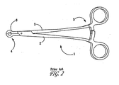
- Forceps 1 includes pivotally connected arms 2 and 3, a head region 4 and a handle region 5.
- Head region 4 comprises a chamber 6 for engaging a cannula or other device.
- DE 20 2004 002 560 U1 discloses a forceps with jaw members defining a cylindrical gripping chamber wherein the jaws taper together from the cylindrical gripping chamber to the distal tips of said jaw members. Embodiments of the present invention offer substantial improvements over these and other prior art forceps.
- the first elongated member includes a first head portion and an opposing first handle portion that is angled in a first direction with respect to the first head portion.
- the first head portion has a first joint component and a tissue contacting surface facing the first direction.
- the second elongated member includes a second head portion and an opposing second handle portion.
- the second head portion employs a second joint component that is configured for engaging the first joint component.
- the first and second joint components are capable of assembly and disassembly without the use of tools. And the first and second joint components are spaced apart from the tissue contacting surface.
- a handle is defined at one end, and a head is defined at an opposing end.
- the head includes first and second jaws, each of which is associated with a respective one of the first and second elongated members and including an inner surface.
- a groove is formed in each of the inner surfaces to collectively define a substantially cylindrical gripping chamber upon converging the two jaws.
- a tissue retracting surface is defined by a surface of at least one of the head and the handle. The tissue retracting surface is oriented orthogonal to the inner surfaces and has a width of at least about 15 mm.
- a pair of forceps having first and second elongated members pivotally connected.
- a handle is defined at one end, and a head is defined at an opposing end.
- a cannula receiving chamber is disposed in the head and has a threaded surface.
- the first and second elongated members are separable via manipulation of the first and second elongated members with respect to each other.
- a pair of forceps including a head portion having a first jaw, and a second jaw pivotally connected to the first jaw.
- Each of the first jaw and the second jaw includes an inner surface having a proximal end and a distal end.
- the inner surfaces are tapered inwardly in a direction from the distal end to the proximal end to define an engagement guide capable of facilitating blind location and engagement of a cannula.
- a groove is formed in each of the inner surfaces to collectively define a cannula-receiving chamber upon converging said first and second jaws.
- the grooves are located at the respective proximal ends of the inner surfaces so that a cannula can be positively engaged by passing the first and second jaws around the cannula via the engagement guide until travel is inhibited (that is, the first and second jaws are bottomed out) and then converging the first and second jaws around the cannula.
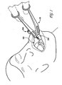
- Figure 1 is a perspective view of one preferred forceps embodiment being used in one preferred application.
- Figure 2 is a top plan view of a prior art pair of forceps.
- Figure 3 is a top plan view of the preferred forceps shown in Figure 1 .
- Figure 4 is a bottom plan view of the preferred forceps shown in Figure 1 .
- Figure 5 is a side view of the preferred forceps shown in Figure 1 .
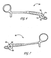
- Figure 6 is a perspective view of one of the elongated members of the preferred forceps shown in Figure 1 .
- Figure 7 is a perspective view of the other elongated member of the preferred forceps shown in Figure 1 .
- FIG. 1 an exemplary pair of forceps 10 is shown in Figure 1 being used in one preferred application-a maxillofacial operation involving inserting self-drilling screws into a human mandible.
- Forceps 10 is shown inserted into the patient's mouth 100 and around a threaded cannula 200.
- exemplary forceps 10 includes first and second elongated members or arms 20 and 30 pivotally connected together.
- a head 12 is defined by respective head portions 21 and 31, and a handle 14 is defined by handle portions 22 and 32.
- Elongated members 20 and 30 are connected at a joint 16.
- joint 16 is non-permanent; that is, the forceps are designed and manufactured to be disassembled for packaging, cleaning/sterilization, and assembled for use. Note that permanent joints can be used in alternative embodiments.
- Each of head portions 21 and 31 includes a jaw 23, 33 having an inner surface 24,34.
- the inner jaw surfaces comprise a groove 25, 35 that collectively define a gripping chamber 18 when jaws 23 and 33 are converged.
- Gripping chamber 18 preferably is threaded to facilitate a secure engagement of a cannula or other device. Non-threaded gripping chambers however can equally be employed. Gripping chamber is shown being substantially cylindrical, but it is not limited to this geometry. Outer surfaces of a cannula or any other device may also be threaded (see, for example, threads 210 on cannula 200 shown in Figure 1 ), such that the threads associated with gripping chamber 18 can engage threads on the device or object being grasped.
- inner jaw surfaces 24 and 34 taper towards each other from their distal ends 26, 36 of the jaws to define an engagement guide ("V-entry”).
- Distal ends 26 and 36 are preferably rounded, or otherwise blunt, to prevent injury to the medical attendant or patient.
- gripping chamber 18 is located at respective proximal ends 27, 37 of the jaws so that a cannula or other device can be positively engaged by "bottoming out” the jaws around a cannula.
- These "V-entry” and “bottoming out” features are optional, and can be employed to facilitate blind location and engagement of a device, particularly when the device is positioned in an area having a limited field of vision, such as, for example, in a patient's mouth.
- forceps 10 can also be used to retract soft tissue. This is shown in Figure 1 .
- the patient's cheek is retracted or pulled away from its normal resting position to enable a medical attendant to observe what is happening inside the mouth, and to permit placement and manipulation of objects into the mouth.
- At least some of the head and/or the handle generally define a tissue contacting surface.
- Soft tissue can generally be retracted through geometrical and/or dimensional aspects of the tissue contacting surface, by simply moving the forceps after contacting the soft tissue, or through a combination of the two.
- forceps 10 have a tissue contacting (retracting) surface 40 that is primarily defined by the outer surface of head portion 21, and partially defined by exposed portions of an outer surface of head portion 31. Depending on the length of the forceps' head and the depth of insertion into the mouth (or other area), tissue contacting surface 40 may also be partially defined by adjacent handle portions 22 and 32. Tissue contacting surface 40 has a width 42 that is preferably between about 5 and 50 mm, more preferably at least about 15 mm, and even more preferably at least about 20 mm.
- FIG. 5 A side view of exemplary forceps 10 is shown in Figure 5 . From this view, one can see that handle 14 can be angled with respect to head 12 at an angle 44. Generally, angle 44 is between about 10 degrees and 90 degrees, preferably between about 10 degrees and 45 degrees, and more preferably between about 20 degrees and 30 degrees. In one preferred embodiment, angle 44 is around 25 degrees. Handle 14 may also be parallel with head 12; that is, angle 44 would be substantially 0 degrees. In preferred embodiments, and as shown in the figures, handle 14 is angled in a direction towards tissue contact surface 40. Handle 14 itself can also contain an angle 46 that is preferably on the order of about 10 degrees to about 30 degrees, and more preferably about 20 degrees, although smaller and larger angles are contemplated by the present invention.
- angle 44 is between about 10 degrees and 90 degrees, preferably between about 10 degrees and 45 degrees, and more preferably between about 20 degrees and 30 degrees. In one preferred embodiment, angle 44 is around 25 degrees. Handle 14 may also be parallel with head 12; that is, angle 44 would
- Angle 46 is defined at the intersection of linear handle sections 47 and 48.
- An elevation change from head 12 to a distal end of handle 14 can be accomplished as shown, through multiple linear sections and corresponding angles (similar or dissimilar in magnitude), through one or more curvilinear sections, through a combination of linear and curvilinear sections, or through other manners known to the skilled artisan.
- handle section 47 (of each handle portion) has a rectangular cross-sectional shape and is oriented so as to maximize the width of the respective handle portions, which in turn, may facilitate the tissue retraction function.
- handle section 48 (of each handle portion) has a circular cross-sectional area. Other cross-sectional shapes can equally be employed.
- the forceps' handle may have a homogenous or heterogeneous cross-sectional shape.
- Head portions 21, 31 and handle portions 22,32 may optionally comprise cavities 60 formed in various surfaces, including the top and bottom surfaces, as is shown in the figures. Cavities 60 allow preferred forceps embodiments to employ wide tissue contacting surfaces without substantially increasing the metal requirements for their manufacture. If cavities are employed, it should be understood that there are no limitations to the size, geometry, or uniformity of the cavities.
- Elongated members 20 and 30 are preferably separable, with our without the use of tools.
- elongated member 20 is shown separated from elongated member 30.
- Elongated member 20 has a male joint component 70 extending from a surface of its head portion 21.
- Male joint component 70 includes a post 72 and a flange 74 disposed circumferentially around post 72, preferably in a non-continuous manner.
- the configuration of post 72 and flange 74 may differ from that shown in Figure 6 .
- Male joint component 70 may be integrally formed with elongated member 20, or may alternately be manufactured separately and then joined to member 20 with any number of techniques.
- Elongated member 30 is depicted in Figure 7 .
- Elongated member 30 has a female joint component 80 defined by an aperture 82 and a rib 84 disposed on the aperture's surface, preferably in a non-continuous manner.
- Female joint component 80 similarly may be integrally formed with elongated member 30 or separately manufactured.
- Aperture 82 may alternately take the form of a recess in head portion 31.
- Elongated members 20 and 30 are simply rotated in an opposite direction and pulled apart for disassembly.
- joints and corresponding joint components can be used to effect the preferred separability aspect. And different types of manipulation and steps may be required for assembly and disassembly in comparison to that described above.
- preferred forceps embodiments may be used for retracting a patient's cheek and/or performing one or more maxillofacial procedures.
- a method for retracting a patient's check comprising the steps of assembling exemplary elongated members 20 and 30 (preferably without the use of tools) and positioning the assembled forceps into a patient's mouth so that the patient's cheek is retracted from its normal resting position.
- Various maxillofacial procedures such as, for example, stabilizing a fractured mandible, can be facilitated via the preferred retracting forceps.
- a cannula is typically inserted through a patient's cheek, during some maxillofacial procedures, to permit the passage of instruments and/or fasteners.
- the forceps can be inserted through the patient's mouth to securely hold the cannula, while also retracting the patient's cheek. After completing the procedure, the forceps can be disassembled for cleaning and/or sterilization.
- the forceps are preferably separable so that surfaces are non-contacting during sterilization to help ensure the sterilization is effective. The forceps can then be reassembled and employed for another chosen procedure.
- Forceps in accordance with preferred embodiments can be made from any bio-inert material, for example, stainless steel or titanium.
- the forceps may optionally contain a coating or medicament.
- the forceps may be made through any number of manufacturing techniques known to the skilled artisan, including, but not limited to, forging and metal injection molding.
Landscapes
- Health & Medical Sciences (AREA)
- Life Sciences & Earth Sciences (AREA)
- Surgery (AREA)
- Molecular Biology (AREA)
- General Health & Medical Sciences (AREA)
- Biomedical Technology (AREA)
- Heart & Thoracic Surgery (AREA)
- Medical Informatics (AREA)
- Nuclear Medicine, Radiotherapy & Molecular Imaging (AREA)
- Animal Behavior & Ethology (AREA)
- Engineering & Computer Science (AREA)
- Public Health (AREA)
- Veterinary Medicine (AREA)
- Ophthalmology & Optometry (AREA)
- Surgical Instruments (AREA)
- Electrotherapy Devices (AREA)
- Steering Control In Accordance With Driving Conditions (AREA)
- Dental Tools And Instruments Or Auxiliary Dental Instruments (AREA)
- Adornments (AREA)
Priority Applications (1)
| Application Number | Priority Date | Filing Date | Title |
|---|---|---|---|
| PL06750046T PL1868514T3 (pl) | 2005-04-13 | 2006-04-12 | Szczypce medyczne i sposób ich stosowania |
Applications Claiming Priority (2)
| Application Number | Priority Date | Filing Date | Title |
|---|---|---|---|
| US11/105,661 US8152834B2 (en) | 2005-04-13 | 2005-04-13 | Forceps and system using same |
| PCT/US2006/013874 WO2006113355A1 (en) | 2005-04-13 | 2006-04-12 | Forceps and system using same |
Publications (2)
| Publication Number | Publication Date |
|---|---|
| EP1868514A1 EP1868514A1 (en) | 2007-12-26 |
| EP1868514B1 true EP1868514B1 (en) | 2009-12-02 |
Family
ID=36716956
Family Applications (1)
| Application Number | Title | Priority Date | Filing Date |
|---|---|---|---|
| EP06750046A Active EP1868514B1 (en) | 2005-04-13 | 2006-04-12 | Forceps and system using same |
Country Status (15)
| Country | Link |
|---|---|
| US (1) | US8152834B2 (enExample) |
| EP (1) | EP1868514B1 (enExample) |
| JP (1) | JP5039026B2 (enExample) |
| KR (1) | KR101277098B1 (enExample) |
| CN (1) | CN101160100B (enExample) |
| AT (1) | ATE450214T1 (enExample) |
| AU (1) | AU2006236779A1 (enExample) |
| BR (1) | BRPI0609409B1 (enExample) |
| CA (1) | CA2604704C (enExample) |
| DE (1) | DE602006010838D1 (enExample) |
| ES (1) | ES2334828T3 (enExample) |
| PL (1) | PL1868514T3 (enExample) |
| TW (1) | TWI380794B (enExample) |
| WO (1) | WO2006113355A1 (enExample) |
| ZA (1) | ZA200708335B (enExample) |
Families Citing this family (28)
| Publication number | Priority date | Publication date | Assignee | Title |
|---|---|---|---|---|
| USD557415S1 (en) * | 2005-11-23 | 2007-12-11 | Karl Storz Gmbh & Co. Kg | Medical instrument |
| FR2946858A1 (fr) * | 2009-06-17 | 2010-12-24 | Alternative Medicale | Instrument a usage medical, notamment chirurgical, a deux branches pivotantes l'une par rapport a l'autre. |
| CN102858263B (zh) * | 2010-04-27 | 2016-01-20 | 斯恩蒂斯有限公司 | 包括基尔希纳氏钢丝压缩的骨固定系统 |
| JP5933527B2 (ja) | 2010-04-27 | 2016-06-08 | ジンテス ゲゼルシャフト ミット ベシュレンクテル ハフツング | 骨固定システム |
| BRPI1001125B1 (pt) * | 2010-04-29 | 2021-06-15 | Adalberto De Carvalho Vale | Ferramenta ergonômica para exodontia atraumática |
| RU2485908C2 (ru) * | 2010-12-07 | 2013-06-27 | Компания с ограниченной ответственностью Глобитек 2000 | Способ создания гемостаза с возможностью восстановления кровотока в трубчатых эластичных структурах организма и устройства для его осуществления |
| US20120302852A1 (en) * | 2011-04-25 | 2012-11-29 | Matos Jeffrey A | Implantable medical device removal/insertion tool |
| US8968306B2 (en) | 2011-08-09 | 2015-03-03 | Covidien Lp | Surgical forceps |
| CN104245233A (zh) * | 2012-01-10 | 2014-12-24 | 考尔坦/威登有限公司 | 手动工具连接 |
| CN102551816B (zh) * | 2012-02-14 | 2014-01-08 | 周剑虹 | 下颌骨髁突骨折复位撑开器 |
| US9345566B2 (en) * | 2012-09-26 | 2016-05-24 | Cook Medical Technologies Llc | Delivery device and system for open surgical repair |
| US20140107658A1 (en) * | 2012-10-11 | 2014-04-17 | Michael J. Yaremchuk | Surgical Instrument |
| JPWO2014103095A1 (ja) * | 2012-12-27 | 2017-01-12 | ディーブイエックス株式会社 | 鉗子 |
| US20150112336A1 (en) * | 2013-10-20 | 2015-04-23 | Kogent Surgical, LLC | Bipolar forceps |
| US20150111171A1 (en) * | 2013-10-21 | 2015-04-23 | Steven Peterson | Coping and crown holder |
| JP5858116B1 (ja) * | 2014-09-09 | 2016-02-10 | 株式会社Ydm | 抜歯鉗子 |
| USD759818S1 (en) * | 2015-04-10 | 2016-06-21 | Steven Peterson | Coping and crown holder |
| US10376277B2 (en) * | 2016-02-18 | 2019-08-13 | Crea Ip B.V. | Serrated forceps |
| US10772676B2 (en) | 2016-05-31 | 2020-09-15 | Kogent Surgical, LLC | Microsurgical bipolar forceps |
| CN106224692A (zh) * | 2016-08-31 | 2016-12-14 | 中船黄埔文冲船舶有限公司 | 一种管口密封装置 |
| CN106264686A (zh) * | 2016-10-25 | 2017-01-04 | 蒲骁麟 | 万向穿刺定位器 |
| CN108420474B (zh) * | 2018-03-14 | 2019-02-26 | 山东大学 | 唇颊、黏骨膜瓣同时牵引拉钩组件及使用方法 |
| CN109171912B (zh) * | 2018-09-10 | 2021-02-02 | 李占勇 | 一种喉部扩张及异物取出装置 |
| KR102180976B1 (ko) * | 2018-09-14 | 2020-11-19 | 이진균 | 치과 임플란트 매식체 제거용 겸자 |
| US11766316B2 (en) * | 2020-06-19 | 2023-09-26 | Greggory Joseph DiLauri | Pin engagement device relating to guided placement in a surgical procedure |
| CN112006766A (zh) * | 2020-08-31 | 2020-12-01 | 上海三友医疗器械股份有限公司 | 钩棒连接组件以及内固定系统 |
| EP4225166A4 (en) * | 2020-10-08 | 2024-10-02 | Acumed LLC | NAIL-BASED BONE FIXATION DEVICES AND SYSTEMS |
| US12144698B2 (en) * | 2021-04-07 | 2024-11-19 | Sappenfield Christopher C | Dental devices and related methods |
Citations (1)
| Publication number | Priority date | Publication date | Assignee | Title |
|---|---|---|---|---|
| DE202004002560U1 (de) * | 2004-02-19 | 2004-04-22 | Helmut Zepf Medizintechnik Gmbh | Dentalmedizinische Zange |
Family Cites Families (89)
| Publication number | Priority date | Publication date | Assignee | Title |
|---|---|---|---|---|
| DE1049533B (de) | 1959-01-29 | Udine Ferruccio Bertoni (Italien) | Kieferdehnschraube | |
| US254643A (en) | 1882-03-07 | Chaeles h | ||
| US256525A (en) | 1882-04-18 | whiting | ||
| US360695A (en) | 1887-04-05 | Dental regulating device | ||
| US620853A (en) * | 1899-03-07 | richter | ||
| US597582A (en) | 1898-01-18 | Teeth-regulator | ||
| US455822A (en) | 1891-07-14 | Sounding-post | ||
| US827392A (en) | 1903-11-16 | 1906-07-31 | Caspar Prangemeier | Implement for driving in nails. |
| US864558A (en) | 1904-08-18 | 1907-08-27 | Gustav F Richter | Separable pivot-joint. |
| US891061A (en) | 1908-01-20 | 1908-06-16 | Carl Einar Hansen | Tongs. |
| US1001042A (en) | 1910-11-28 | 1911-08-22 | Clyde C Kadel | Sectional nut. |
| US1021110A (en) | 1911-09-18 | 1912-03-26 | John Niewohner | Nut-lock. |
| US1333243A (en) | 1919-03-15 | 1920-03-09 | Wilson S Bowers | Pliers |
| US1973569A (en) | 1933-05-12 | 1934-09-11 | Robert B Kurtz | Surgical instrument |
| DE743853C (de) | 1939-03-11 | 1944-01-04 | Alois Hipp | Loesbares Gelenk fuer chirurgische Instrumente o. dgl. |
| US2375094A (en) * | 1943-09-29 | 1945-05-01 | White S Dental Mfg Co | Orthodontic pliers |
| US2387928A (en) | 1944-01-27 | 1945-10-30 | Monnier Russel | Hand tool |
| US2632661A (en) * | 1948-08-14 | 1953-03-24 | Cristofv Cristjo | Joint for surgical instruments |
| US2641149A (en) | 1951-06-27 | 1953-06-09 | Petersen Mfg | Gripping tool |
| AT192049B (de) | 1956-02-13 | 1957-09-25 | Franz Fischer | Vorrichtung zum Regeln der Zahnstellung |
| US2932894A (en) * | 1957-04-03 | 1960-04-19 | Joseph A Sheldon | Dental instrument for ligating, placing, and removing pins, adjusting, etc. |
| US3161085A (en) | 1963-01-25 | 1964-12-15 | James T Pratt | Fuse puller |
| US3202023A (en) | 1963-04-05 | 1965-08-24 | John T Parker | Gutter clamp |
| US3329001A (en) | 1964-07-13 | 1967-07-04 | Acro Die And Stamping Co | Hand tool for adjusting needle eye laps |
| US3454001A (en) | 1965-06-03 | 1969-07-08 | Hugo Stockfisch | Orthopedic treatment apparatus for the jaw bones |
| US3473528A (en) | 1966-04-20 | 1969-10-21 | Sidney Mishkin | Sternal stabilizer |
| US3653284A (en) | 1970-10-27 | 1972-04-04 | George O Pynchon | Plastic pipe gripping tool |
| US4035917A (en) * | 1975-12-23 | 1977-07-19 | James Norman Roberts | Reinforcing dental pin cutter and retainer |
| US4144643A (en) | 1977-01-19 | 1979-03-20 | Krygier Stanley J | Maxillary orthopedic suture separating orthodontic appliance |
| USD254643S (en) * | 1978-02-06 | 1980-04-08 | Henry Ashenfarb | Illuminated picture frame |
| US4179782A (en) | 1978-05-01 | 1979-12-25 | The United States Of America As Represented By The Secretary Of The Navy | Cable terminal-ferrule attaching apparatus |
| USD256525S (en) * | 1978-09-25 | 1980-08-26 | Contempo Metal Furniture Co. of Calif. | Chair |
| US4318316A (en) | 1979-10-12 | 1982-03-09 | Guilliams Charles M | Locking pliers for gripping threaded hanger rods |
| US4308863A (en) | 1979-10-18 | 1982-01-05 | Ace Orthopedic Manufacturing, Inc. | External fixation device |
| US4361130A (en) | 1980-10-28 | 1982-11-30 | Mark Talaba | Glass sheet shaping and trimming (grozing) tool and method of use |
| US4353273A (en) | 1980-10-30 | 1982-10-12 | Inland Manufacturing Company | Pliers for plastic radiator tank replacement |
| US4386603A (en) | 1981-03-23 | 1983-06-07 | Mayfield Jack K | Distraction device for spinal distraction systems |
| DE3121271A1 (de) | 1981-05-29 | 1982-12-23 | Max Bernhard 7900 Ulm Ulrich | Distraktionsgeraet zur korrektur insbesondere kyphotischer wirbelsaeulenbereiche |
| US4730608A (en) | 1986-03-05 | 1988-03-15 | Schlein Allen P | External bone-anchoring fixator |
| US4848368A (en) | 1988-04-25 | 1989-07-18 | Kronner Richard F | Universal external fixation frame assembly |
| USD323214S (en) * | 1989-03-30 | 1992-01-14 | ACE Surgical Supply Co. | Swivel forcep screw driver holder for dental implants |
| US5023989A (en) | 1989-11-22 | 1991-06-18 | Hargrave David L | Tool for repairing pop-up sprinklers |
| US5120221A (en) * | 1989-12-29 | 1992-06-09 | Orenstein Jonathan H | Dental clamp for use in implant restorative dentistry |
| DE4006111C1 (enExample) * | 1990-02-27 | 1991-05-08 | Orbis-Werk Groten Gmbh + Co Kg, 4422 Ahaus, De | |
| DE4115548C2 (de) | 1990-05-17 | 1996-11-21 | Storz Karl | Chirurgische Zange zur Anwendung in der Laparoskopie |
| US5147358A (en) | 1990-10-23 | 1992-09-15 | Remmler Daniel J | Cranial fixation-distraction and positioning apparatus and method |
| US5197879A (en) * | 1991-09-06 | 1993-03-30 | Fowler Iii Hudson D | Orthodontic, medical, dental tool |
| US5232360A (en) * | 1991-09-16 | 1993-08-03 | Luis Ingels | Orthodontic pliers |
| US5885283A (en) | 1992-08-04 | 1999-03-23 | Gittleman; Neal B. | Osteogenic mandibular distention apparatus and method |
| DE69420273T2 (de) | 1993-05-06 | 1999-12-09 | Richard W. George | Gebissdehner |
| JP3532230B2 (ja) * | 1993-09-17 | 2004-05-31 | 株式会社ジーシー | インプラントフィクスチャー及びインプラントフィクスチャー用鉗子 |
| US5391181A (en) | 1993-10-22 | 1995-02-21 | Zimmer, Inc. | Orthopaedic holding forceps |
| IL110517A (en) | 1994-07-31 | 1998-08-16 | Technion Res & Dev Foundation | Padded artery blocker |
| EP0817596B1 (de) | 1995-03-15 | 1998-09-02 | Bernhard Förster GmbH | Dehnschraube zum korrigieren von fehlstellungen von zähnen |
| US5575790A (en) | 1995-03-28 | 1996-11-19 | Rensselaer Polytechnic Institute | Shape memory alloy internal linear actuator for use in orthopedic correction |
| AUPN205795A0 (en) | 1995-03-30 | 1995-04-27 | Palmisano, Richard George | Apparatus and methods for treatment of obstructive sleep apnea and/or snoring |
| WO1997012568A1 (en) | 1995-10-02 | 1997-04-10 | Remmler Daniel J | Implantable apparatus, matrix and method for correction of craniofacial bone deformities |
| CA2191405C (en) | 1995-12-01 | 2003-03-25 | David Walker | Telescopic bone plate for use in bone lengthening by distraction osteogenesis |
| US6256855B1 (en) | 1995-12-04 | 2001-07-10 | Richard L. Schall | Hinge pin remover |
| US5799381A (en) | 1996-01-16 | 1998-09-01 | Gannon; Todd Edward | Stud nail pliers apparatus |
| US5746757A (en) * | 1996-01-17 | 1998-05-05 | Mcguire; David A. | Suturing jig and method for using same |
| US5829323A (en) | 1996-08-27 | 1998-11-03 | Liston; Douglas A. | Nail spike guide and support hand tool |
| DE29615820U1 (de) | 1996-09-12 | 1996-10-31 | Bernhard Förster GmbH, 75172 Pforzheim | Palatinalsplitschraube |
| US5769850A (en) | 1996-10-16 | 1998-06-23 | Chin; Martin | Apparatus and method for submergible, self-retaining distraction osteogenesis |
| US5885290A (en) | 1996-12-09 | 1999-03-23 | Guerrero; Cesar A. | Intra-oral bone distraction device |
| EP0846446B1 (en) | 1996-12-09 | 2003-08-20 | Leone S.p.A. | Orthodontic screw for a fast expansion on the anterior sector of the maxillary arch |
| US5810878A (en) | 1997-02-12 | 1998-09-22 | Sdgi Holdings, Inc. | Rod introducer forceps |
| US5984864A (en) * | 1997-10-07 | 1999-11-16 | Ethicon Endo-Surgery, Inc. | Tissue stabilization device for use during surgery |
| US5891161A (en) * | 1997-11-24 | 1999-04-06 | Graser; Robert E. | Wire insertion guide and method of use in pinning bones |
| US6520772B2 (en) | 1998-04-23 | 2003-02-18 | Michael O. Williams | Bimaxillary jaw expanding appliance |
| DE19921822A1 (de) | 1998-05-13 | 1999-11-18 | Ormco Corp | Orthodontische Schraubdehnvorrichtung |
| US6361541B1 (en) | 1998-07-17 | 2002-03-26 | The University Of Iowa Research Foundation | Surgical instrument for extracting tissue ingrowth from a permeable member of an implanted catheter |
| US6328745B1 (en) | 1998-11-24 | 2001-12-11 | The Trustees Of Columbia University In The City Of New York | Palate expander |
| US6206882B1 (en) | 1999-03-30 | 2001-03-27 | Surgical Dynamics Inc. | Plating system for the spine |
| US20010004858A1 (en) | 1999-04-13 | 2001-06-28 | Robert E. Kachergius | Fastener extractor |
| AU7360600A (en) * | 1999-09-08 | 2001-04-24 | Ray Adams | Percutaneous entry system and method |
| US6761725B1 (en) * | 1999-09-08 | 2004-07-13 | Jeffrey Grayzel | Percutaneous entry system and method |
| US6051004A (en) | 1999-09-20 | 2000-04-18 | Gill; Darrell | Combination needle holder and suture cutter medical instrument |
| BE1013222A3 (nl) | 2000-01-11 | 2001-11-06 | Mommaerts Maurice Yves | Apparaat voor intraorale distractieosteotomie ter verbreding van de bovenkaak. |
| JP3333180B2 (ja) | 2000-03-30 | 2002-10-07 | 和子 川口 | 歯冠修復物等の撤去用器具 |
| US20030120306A1 (en) * | 2000-04-21 | 2003-06-26 | Vascular Control System | Method and apparatus for the detection and occlusion of blood vessels |
| GB0014120D0 (en) * | 2000-06-10 | 2000-08-02 | Sinton Richard T | Hand instrument |
| USD455822S1 (en) * | 2001-04-05 | 2002-04-16 | Kohler Co. | Water closet |
| GB0109932D0 (en) * | 2001-04-23 | 2001-06-13 | Sullman Russell | Tooth extraction device |
| US6428544B1 (en) * | 2001-07-16 | 2002-08-06 | Third Millennium Engineering, Llc | Insertion tool for use with trial intervertebral distraction spacers |
| US7351248B2 (en) | 2002-03-25 | 2008-04-01 | Tri-State Hospital Supply Corporation | Surgical instrument with snag free box hinge |
| US7637912B2 (en) * | 2003-05-27 | 2009-12-29 | Hoya Corporation | Surgical instruments |
| US20050004590A1 (en) | 2003-07-01 | 2005-01-06 | Waters Amneris C. | Medical device to remove hubs/ends of intravenous tubing |
| US7165970B2 (en) * | 2004-03-01 | 2007-01-23 | Garrison Dental Solutions, Inc. | Dental instrument |
-
2005
- 2005-04-13 US US11/105,661 patent/US8152834B2/en active Active
-
2006
- 2006-04-12 PL PL06750046T patent/PL1868514T3/pl unknown
- 2006-04-12 EP EP06750046A patent/EP1868514B1/en active Active
- 2006-04-12 DE DE602006010838T patent/DE602006010838D1/de active Active
- 2006-04-12 ES ES06750046T patent/ES2334828T3/es active Active
- 2006-04-12 KR KR1020077022407A patent/KR101277098B1/ko not_active Expired - Fee Related
- 2006-04-12 AU AU2006236779A patent/AU2006236779A1/en not_active Abandoned
- 2006-04-12 WO PCT/US2006/013874 patent/WO2006113355A1/en not_active Ceased
- 2006-04-12 CN CN2006800119692A patent/CN101160100B/zh active Active
- 2006-04-12 CA CA2604704A patent/CA2604704C/en not_active Expired - Fee Related
- 2006-04-12 JP JP2008506692A patent/JP5039026B2/ja active Active
- 2006-04-12 TW TW095113056A patent/TWI380794B/zh active
- 2006-04-12 AT AT06750046T patent/ATE450214T1/de active
- 2006-04-12 BR BRPI0609409-0A patent/BRPI0609409B1/pt active IP Right Grant
-
2007
- 2007-09-28 ZA ZA200708335A patent/ZA200708335B/xx unknown
Patent Citations (1)
| Publication number | Priority date | Publication date | Assignee | Title |
|---|---|---|---|---|
| DE202004002560U1 (de) * | 2004-02-19 | 2004-04-22 | Helmut Zepf Medizintechnik Gmbh | Dentalmedizinische Zange |
Also Published As
| Publication number | Publication date |
|---|---|
| BRPI0609409A2 (pt) | 2010-04-06 |
| AU2006236779A1 (en) | 2006-10-26 |
| CA2604704A1 (en) | 2006-10-26 |
| KR101277098B1 (ko) | 2013-06-20 |
| CN101160100B (zh) | 2013-03-06 |
| TWI380794B (zh) | 2013-01-01 |
| JP2008536568A (ja) | 2008-09-11 |
| PL1868514T3 (pl) | 2010-04-30 |
| JP5039026B2 (ja) | 2012-10-03 |
| CA2604704C (en) | 2014-10-21 |
| KR20080009066A (ko) | 2008-01-24 |
| CN101160100A (zh) | 2008-04-09 |
| US20060235466A1 (en) | 2006-10-19 |
| EP1868514A1 (en) | 2007-12-26 |
| ATE450214T1 (de) | 2009-12-15 |
| TW200716051A (en) | 2007-05-01 |
| BRPI0609409B1 (pt) | 2023-01-24 |
| DE602006010838D1 (de) | 2010-01-14 |
| WO2006113355A1 (en) | 2006-10-26 |
| US8152834B2 (en) | 2012-04-10 |
| ES2334828T3 (es) | 2010-03-16 |
| ZA200708335B (en) | 2008-11-26 |
Similar Documents
| Publication | Publication Date | Title |
|---|---|---|
| EP1868514B1 (en) | Forceps and system using same | |
| EP0972493B1 (en) | Ultrasonic trocar | |
| CA2864697C (en) | Hammer toe implant and method | |
| JP6847096B2 (ja) | 骨固定用インプラントシステム | |
| TWI874199B (zh) | 深度止擋件,以及組合之骨鑿及深度止擋件總成 | |
| JP2013532511A (ja) | 骨接合装置 | |
| CN108272500A (zh) | 自保持式螺钉头 | |
| US11141163B2 (en) | Circular stapling device with anvil rotation locking structure | |
| US9907546B2 (en) | Surgical elevator with suction | |
| CN215349140U (zh) | 外科手术器械系统、用于外科手术器械的定位引导件以及内窥镜外科手术钉施加器系统 | |
| JP5937768B2 (ja) | 骨接合具 | |
| US7582093B2 (en) | Screw extraction and insertion device | |
| US20140128890A1 (en) | Medical device and related methods of use | |
| CN103974669B (zh) | 用于螺钉的自保持结构 | |
| US9320422B1 (en) | Surgical retractor | |
| US8702601B2 (en) | Medical access device having a protection against an excessive application of leverage | |
| JP6513791B2 (ja) | 外科用ケーブルの締結器及びその製造方法 | |
| AU2019284089A1 (en) | Access assembly including flexible cannula | |
| US20250152181A1 (en) | Revision goal post osteotome | |
| CN110709020A (zh) | 隧道装置 | |
| KR101856881B1 (ko) | 외과용 켈리 포셉 | |
| JP6663270B2 (ja) | 手術用具 | |
| BR112020008780B1 (pt) | Gaiola para ossos | |
| AU2012203021A1 (en) | Screw extraction and insertion device | |
| TW201420073A (zh) | 拆卸式的復位、加壓骨釘 |
Legal Events
| Date | Code | Title | Description |
|---|---|---|---|
| PUAI | Public reference made under article 153(3) epc to a published international application that has entered the european phase |
Free format text: ORIGINAL CODE: 0009012 |
|
| 17P | Request for examination filed |
Effective date: 20070928 |
|
| AK | Designated contracting states |
Kind code of ref document: A1 Designated state(s): AT BE BG CH CY CZ DE DK EE ES FI FR GB GR HU IE IS IT LI LT LU LV MC NL PL PT RO SE SI SK TR |
|
| RAP1 | Party data changed (applicant data changed or rights of an application transferred) |
Owner name: SYNTHES GMBH |
|
| 17Q | First examination report despatched |
Effective date: 20080304 |
|
| DAX | Request for extension of the european patent (deleted) | ||
| GRAP | Despatch of communication of intention to grant a patent |
Free format text: ORIGINAL CODE: EPIDOSNIGR1 |
|
| GRAS | Grant fee paid |
Free format text: ORIGINAL CODE: EPIDOSNIGR3 |
|
| GRAA | (expected) grant |
Free format text: ORIGINAL CODE: 0009210 |
|
| AK | Designated contracting states |
Kind code of ref document: B1 Designated state(s): AT BE BG CH CY CZ DE DK EE ES FI FR GB GR HU IE IS IT LI LT LU LV MC NL PL PT RO SE SI SK TR |
|
| REG | Reference to a national code |
Ref country code: GB Ref legal event code: FG4D |
|
| REG | Reference to a national code |
Ref country code: CH Ref legal event code: EP Ref country code: CH Ref legal event code: NV Representative=s name: DR. LUSUARDI AG |
|
| REG | Reference to a national code |
Ref country code: IE Ref legal event code: FG4D |
|
| REF | Corresponds to: |
Ref document number: 602006010838 Country of ref document: DE Date of ref document: 20100114 Kind code of ref document: P |
|
| REG | Reference to a national code |
Ref country code: SE Ref legal event code: TRGR |
|
| REG | Reference to a national code |
Ref country code: ES Ref legal event code: FG2A Ref document number: 2334828 Country of ref document: ES Kind code of ref document: T3 |
|
| REG | Reference to a national code |
Ref country code: NL Ref legal event code: VDEP Effective date: 20091202 |
|
| PG25 | Lapsed in a contracting state [announced via postgrant information from national office to epo] |
Ref country code: LT Free format text: LAPSE BECAUSE OF FAILURE TO SUBMIT A TRANSLATION OF THE DESCRIPTION OR TO PAY THE FEE WITHIN THE PRESCRIBED TIME-LIMIT Effective date: 20091202 Ref country code: FI Free format text: LAPSE BECAUSE OF FAILURE TO SUBMIT A TRANSLATION OF THE DESCRIPTION OR TO PAY THE FEE WITHIN THE PRESCRIBED TIME-LIMIT Effective date: 20091202 |
|
| REG | Reference to a national code |
Ref country code: PL Ref legal event code: T3 |
|
| LTIE | Lt: invalidation of european patent or patent extension |
Effective date: 20091202 |
|
| PG25 | Lapsed in a contracting state [announced via postgrant information from national office to epo] |
Ref country code: SI Free format text: LAPSE BECAUSE OF FAILURE TO SUBMIT A TRANSLATION OF THE DESCRIPTION OR TO PAY THE FEE WITHIN THE PRESCRIBED TIME-LIMIT Effective date: 20091202 Ref country code: CY Free format text: LAPSE BECAUSE OF FAILURE TO SUBMIT A TRANSLATION OF THE DESCRIPTION OR TO PAY THE FEE WITHIN THE PRESCRIBED TIME-LIMIT Effective date: 20091202 Ref country code: LV Free format text: LAPSE BECAUSE OF FAILURE TO SUBMIT A TRANSLATION OF THE DESCRIPTION OR TO PAY THE FEE WITHIN THE PRESCRIBED TIME-LIMIT Effective date: 20091202 |
|
| PGFP | Annual fee paid to national office [announced via postgrant information from national office to epo] |
Ref country code: PL Payment date: 20100303 Year of fee payment: 5 |
|
| REG | Reference to a national code |
Ref country code: HU Ref legal event code: AG4A Ref document number: E007554 Country of ref document: HU |
|
| PG25 | Lapsed in a contracting state [announced via postgrant information from national office to epo] |
Ref country code: RO Free format text: LAPSE BECAUSE OF FAILURE TO SUBMIT A TRANSLATION OF THE DESCRIPTION OR TO PAY THE FEE WITHIN THE PRESCRIBED TIME-LIMIT Effective date: 20091202 Ref country code: PT Free format text: LAPSE BECAUSE OF FAILURE TO SUBMIT A TRANSLATION OF THE DESCRIPTION OR TO PAY THE FEE WITHIN THE PRESCRIBED TIME-LIMIT Effective date: 20100402 Ref country code: NL Free format text: LAPSE BECAUSE OF FAILURE TO SUBMIT A TRANSLATION OF THE DESCRIPTION OR TO PAY THE FEE WITHIN THE PRESCRIBED TIME-LIMIT Effective date: 20091202 Ref country code: EE Free format text: LAPSE BECAUSE OF FAILURE TO SUBMIT A TRANSLATION OF THE DESCRIPTION OR TO PAY THE FEE WITHIN THE PRESCRIBED TIME-LIMIT Effective date: 20091202 Ref country code: BG Free format text: LAPSE BECAUSE OF FAILURE TO SUBMIT A TRANSLATION OF THE DESCRIPTION OR TO PAY THE FEE WITHIN THE PRESCRIBED TIME-LIMIT Effective date: 20100302 Ref country code: IS Free format text: LAPSE BECAUSE OF FAILURE TO SUBMIT A TRANSLATION OF THE DESCRIPTION OR TO PAY THE FEE WITHIN THE PRESCRIBED TIME-LIMIT Effective date: 20100402 |
|
| PGFP | Annual fee paid to national office [announced via postgrant information from national office to epo] |
Ref country code: HU Payment date: 20100329 Year of fee payment: 5 |
|
| PG25 | Lapsed in a contracting state [announced via postgrant information from national office to epo] |
Ref country code: CZ Free format text: LAPSE BECAUSE OF FAILURE TO SUBMIT A TRANSLATION OF THE DESCRIPTION OR TO PAY THE FEE WITHIN THE PRESCRIBED TIME-LIMIT Effective date: 20091202 Ref country code: SK Free format text: LAPSE BECAUSE OF FAILURE TO SUBMIT A TRANSLATION OF THE DESCRIPTION OR TO PAY THE FEE WITHIN THE PRESCRIBED TIME-LIMIT Effective date: 20091202 Ref country code: BE Free format text: LAPSE BECAUSE OF FAILURE TO SUBMIT A TRANSLATION OF THE DESCRIPTION OR TO PAY THE FEE WITHIN THE PRESCRIBED TIME-LIMIT Effective date: 20091202 |
|
| PLBE | No opposition filed within time limit |
Free format text: ORIGINAL CODE: 0009261 |
|
| STAA | Information on the status of an ep patent application or granted ep patent |
Free format text: STATUS: NO OPPOSITION FILED WITHIN TIME LIMIT |
|
| PG25 | Lapsed in a contracting state [announced via postgrant information from national office to epo] |
Ref country code: GR Free format text: LAPSE BECAUSE OF FAILURE TO SUBMIT A TRANSLATION OF THE DESCRIPTION OR TO PAY THE FEE WITHIN THE PRESCRIBED TIME-LIMIT Effective date: 20100303 |
|
| 26N | No opposition filed |
Effective date: 20100903 |
|
| PG25 | Lapsed in a contracting state [announced via postgrant information from national office to epo] |
Ref country code: MC Free format text: LAPSE BECAUSE OF NON-PAYMENT OF DUE FEES Effective date: 20100430 |
|
| PGFP | Annual fee paid to national office [announced via postgrant information from national office to epo] |
Ref country code: SE Payment date: 20100409 Year of fee payment: 5 |
|
| PG25 | Lapsed in a contracting state [announced via postgrant information from national office to epo] |
Ref country code: IE Free format text: LAPSE BECAUSE OF NON-PAYMENT OF DUE FEES Effective date: 20100412 Ref country code: DK Free format text: LAPSE BECAUSE OF FAILURE TO SUBMIT A TRANSLATION OF THE DESCRIPTION OR TO PAY THE FEE WITHIN THE PRESCRIBED TIME-LIMIT Effective date: 20091202 |
|
| REG | Reference to a national code |
Ref country code: SE Ref legal event code: EUG |
|
| PG25 | Lapsed in a contracting state [announced via postgrant information from national office to epo] |
Ref country code: HU Free format text: LAPSE BECAUSE OF NON-PAYMENT OF DUE FEES Effective date: 20110413 |
|
| PG25 | Lapsed in a contracting state [announced via postgrant information from national office to epo] |
Ref country code: LU Free format text: LAPSE BECAUSE OF NON-PAYMENT OF DUE FEES Effective date: 20100412 |
|
| PG25 | Lapsed in a contracting state [announced via postgrant information from national office to epo] |
Ref country code: PL Free format text: LAPSE BECAUSE OF NON-PAYMENT OF DUE FEES Effective date: 20110412 Ref country code: TR Free format text: LAPSE BECAUSE OF FAILURE TO SUBMIT A TRANSLATION OF THE DESCRIPTION OR TO PAY THE FEE WITHIN THE PRESCRIBED TIME-LIMIT Effective date: 20091202 |
|
| REG | Reference to a national code |
Ref country code: PL Ref legal event code: LAPE |
|
| PG25 | Lapsed in a contracting state [announced via postgrant information from national office to epo] |
Ref country code: SE Free format text: LAPSE BECAUSE OF NON-PAYMENT OF DUE FEES Effective date: 20110413 |
|
| PGFP | Annual fee paid to national office [announced via postgrant information from national office to epo] |
Ref country code: ES Payment date: 20150310 Year of fee payment: 10 |
|
| PGFP | Annual fee paid to national office [announced via postgrant information from national office to epo] |
Ref country code: AT Payment date: 20150325 Year of fee payment: 10 |
|
| REG | Reference to a national code |
Ref country code: FR Ref legal event code: PLFP Year of fee payment: 11 |
|
| REG | Reference to a national code |
Ref country code: AT Ref legal event code: MM01 Ref document number: 450214 Country of ref document: AT Kind code of ref document: T Effective date: 20160412 |
|
| PG25 | Lapsed in a contracting state [announced via postgrant information from national office to epo] |
Ref country code: AT Free format text: LAPSE BECAUSE OF NON-PAYMENT OF DUE FEES Effective date: 20160412 |
|
| REG | Reference to a national code |
Ref country code: FR Ref legal event code: PLFP Year of fee payment: 12 |
|
| REG | Reference to a national code |
Ref country code: FR Ref legal event code: PLFP Year of fee payment: 13 |
|
| PG25 | Lapsed in a contracting state [announced via postgrant information from national office to epo] |
Ref country code: ES Free format text: LAPSE BECAUSE OF NON-PAYMENT OF DUE FEES Effective date: 20160413 |
|
| REG | Reference to a national code |
Ref country code: ES Ref legal event code: FD2A Effective date: 20180626 |
|
| PGFP | Annual fee paid to national office [announced via postgrant information from national office to epo] |
Ref country code: FR Payment date: 20250310 Year of fee payment: 20 |
|
| PGFP | Annual fee paid to national office [announced via postgrant information from national office to epo] |
Ref country code: IT Payment date: 20250320 Year of fee payment: 20 Ref country code: GB Payment date: 20250306 Year of fee payment: 20 |
|
| PGFP | Annual fee paid to national office [announced via postgrant information from national office to epo] |
Ref country code: DE Payment date: 20250305 Year of fee payment: 20 |
|
| PGFP | Annual fee paid to national office [announced via postgrant information from national office to epo] |
Ref country code: CH Payment date: 20250501 Year of fee payment: 20 |