EP1842836A1 - Vorrichtung und verfahren zur verarbeitung von zementofenverbrennungsabgas - Google Patents
Vorrichtung und verfahren zur verarbeitung von zementofenverbrennungsabgas Download PDFInfo
- Publication number
- EP1842836A1 EP1842836A1 EP05822629A EP05822629A EP1842836A1 EP 1842836 A1 EP1842836 A1 EP 1842836A1 EP 05822629 A EP05822629 A EP 05822629A EP 05822629 A EP05822629 A EP 05822629A EP 1842836 A1 EP1842836 A1 EP 1842836A1
- Authority
- EP
- European Patent Office
- Prior art keywords
- catalyst
- exhaust gas
- combustion exhaust
- cement kiln
- kiln combustion
- Prior art date
- Legal status (The legal status is an assumption and is not a legal conclusion. Google has not performed a legal analysis and makes no representation as to the accuracy of the status listed.)
- Withdrawn
Links
Images


Classifications
-
- B—PERFORMING OPERATIONS; TRANSPORTING
- B01—PHYSICAL OR CHEMICAL PROCESSES OR APPARATUS IN GENERAL
- B01D—SEPARATION
- B01D53/00—Separation of gases or vapours; Recovering vapours of volatile solvents from gases; Chemical or biological purification of waste gases, e.g. engine exhaust gases, smoke, fumes, flue gases, aerosols
- B01D53/34—Chemical or biological purification of waste gases
- B01D53/74—General processes for purification of waste gases; Apparatus or devices specially adapted therefor
- B01D53/86—Catalytic processes
- B01D53/8621—Removing nitrogen compounds
- B01D53/8625—Nitrogen oxides
-
- C—CHEMISTRY; METALLURGY
- C04—CEMENTS; CONCRETE; ARTIFICIAL STONE; CERAMICS; REFRACTORIES
- C04B—LIME, MAGNESIA; SLAG; CEMENTS; COMPOSITIONS THEREOF, e.g. MORTARS, CONCRETE OR LIKE BUILDING MATERIALS; ARTIFICIAL STONE; CERAMICS; REFRACTORIES; TREATMENT OF NATURAL STONE
- C04B7/00—Hydraulic cements
- C04B7/36—Manufacture of hydraulic cements in general
- C04B7/60—Methods for eliminating alkali metals or compounds thereof, e.g. from the raw materials or during the burning process; methods for eliminating other harmful components
-
- B—PERFORMING OPERATIONS; TRANSPORTING
- B01—PHYSICAL OR CHEMICAL PROCESSES OR APPARATUS IN GENERAL
- B01D—SEPARATION
- B01D53/00—Separation of gases or vapours; Recovering vapours of volatile solvents from gases; Chemical or biological purification of waste gases, e.g. engine exhaust gases, smoke, fumes, flue gases, aerosols
- B01D53/34—Chemical or biological purification of waste gases
- B01D53/74—General processes for purification of waste gases; Apparatus or devices specially adapted therefor
- B01D53/86—Catalytic processes
- B01D53/864—Removing carbon monoxide or hydrocarbons
-
- B—PERFORMING OPERATIONS; TRANSPORTING
- B01—PHYSICAL OR CHEMICAL PROCESSES OR APPARATUS IN GENERAL
- B01D—SEPARATION
- B01D53/00—Separation of gases or vapours; Recovering vapours of volatile solvents from gases; Chemical or biological purification of waste gases, e.g. engine exhaust gases, smoke, fumes, flue gases, aerosols
- B01D53/34—Chemical or biological purification of waste gases
- B01D53/74—General processes for purification of waste gases; Apparatus or devices specially adapted therefor
- B01D53/86—Catalytic processes
- B01D53/8668—Removing organic compounds not provided for in B01D53/8603 - B01D53/8665
-
- C—CHEMISTRY; METALLURGY
- C04—CEMENTS; CONCRETE; ARTIFICIAL STONE; CERAMICS; REFRACTORIES
- C04B—LIME, MAGNESIA; SLAG; CEMENTS; COMPOSITIONS THEREOF, e.g. MORTARS, CONCRETE OR LIKE BUILDING MATERIALS; ARTIFICIAL STONE; CERAMICS; REFRACTORIES; TREATMENT OF NATURAL STONE
- C04B7/00—Hydraulic cements
- C04B7/36—Manufacture of hydraulic cements in general
- C04B7/43—Heat treatment, e.g. precalcining, burning, melting; Cooling
- C04B7/436—Special arrangements for treating part or all of the cement kiln dust
-
- F—MECHANICAL ENGINEERING; LIGHTING; HEATING; WEAPONS; BLASTING
- F27—FURNACES; KILNS; OVENS; RETORTS
- F27B—FURNACES, KILNS, OVENS, OR RETORTS IN GENERAL; OPEN SINTERING OR LIKE APPARATUS
- F27B7/00—Rotary-drum furnaces, i.e. horizontal or slightly inclined
- F27B7/20—Details, accessories, or equipment peculiar to rotary-drum furnaces
- F27B7/2016—Arrangements of preheating devices for the charge
- F27B7/2025—Arrangements of preheating devices for the charge consisting of a single string of cyclones
- F27B7/2033—Arrangements of preheating devices for the charge consisting of a single string of cyclones with means for precalcining the raw material
-
- F—MECHANICAL ENGINEERING; LIGHTING; HEATING; WEAPONS; BLASTING
- F27—FURNACES; KILNS; OVENS; RETORTS
- F27D—DETAILS OR ACCESSORIES OF FURNACES, KILNS, OVENS, OR RETORTS, IN SO FAR AS THEY ARE OF KINDS OCCURRING IN MORE THAN ONE KIND OF FURNACE
- F27D17/00—Arrangements for using waste heat; Arrangements for using, or disposing of, waste gases
- F27D17/008—Arrangements for using waste heat; Arrangements for using, or disposing of, waste gases cleaning gases
-
- B—PERFORMING OPERATIONS; TRANSPORTING
- B01—PHYSICAL OR CHEMICAL PROCESSES OR APPARATUS IN GENERAL
- B01D—SEPARATION
- B01D2255/00—Catalysts
- B01D2255/10—Noble metals or compounds thereof
-
- B—PERFORMING OPERATIONS; TRANSPORTING
- B01—PHYSICAL OR CHEMICAL PROCESSES OR APPARATUS IN GENERAL
- B01D—SEPARATION
- B01D2255/00—Catalysts
- B01D2255/20—Metals or compounds thereof
- B01D2255/207—Transition metals
- B01D2255/20707—Titanium
-
- B—PERFORMING OPERATIONS; TRANSPORTING
- B01—PHYSICAL OR CHEMICAL PROCESSES OR APPARATUS IN GENERAL
- B01D—SEPARATION
- B01D2255/00—Catalysts
- B01D2255/20—Metals or compounds thereof
- B01D2255/207—Transition metals
- B01D2255/20723—Vanadium
-
- Y—GENERAL TAGGING OF NEW TECHNOLOGICAL DEVELOPMENTS; GENERAL TAGGING OF CROSS-SECTIONAL TECHNOLOGIES SPANNING OVER SEVERAL SECTIONS OF THE IPC; TECHNICAL SUBJECTS COVERED BY FORMER USPC CROSS-REFERENCE ART COLLECTIONS [XRACs] AND DIGESTS
- Y02—TECHNOLOGIES OR APPLICATIONS FOR MITIGATION OR ADAPTATION AGAINST CLIMATE CHANGE
- Y02A—TECHNOLOGIES FOR ADAPTATION TO CLIMATE CHANGE
- Y02A50/00—TECHNOLOGIES FOR ADAPTATION TO CLIMATE CHANGE in human health protection, e.g. against extreme weather
- Y02A50/20—Air quality improvement or preservation, e.g. vehicle emission control or emission reduction by using catalytic converters
Definitions
- the present invention relates to a device and a method for processing cement kiln combustion exhaust gas to remove harmful substances such as dust, NOx, persistent organic pollutants including dioxins, a volatile organic compound and CO.
- a cement burning facility 21 comprises a preheater 22, a calciner 23, a cement kiln 24, a clinker cooler 25 and so on, and cement raw meal R, which is fed to the preheater 22 from raw material supplying system, is preheated in the preheater 22, calcined in the calciner 23, burned in the cement kiln 24, and produced clinker is cooled in the clinker cooler 25.
- combustion exhaust gas from the cement kiln 24 is processed through desulferization in the preheater 22 and dust collection using an electric precipitator 26 since limestone as a main raw material has a property to adsorb SOx, and processed combustion exhaust gas is discharged in the atmosphere through a fan 27 and a stack 28.
- This technology comprises the steps of: bleeding a part of combustion exhaust gas from the inlet hood of a cement kiln; supplying cooling air to the bled gas to cool it to 600-800°C; introducing the cooled exhaust gas into a cyclone to catch coarse grain dust through separation; introducing the caught coarse grain dust to the kiln inlet hood for circulation; introducing a part of cyclone exhaust gas to the kiln inlet hood to recover heat of the remainder of cyclone exhaust gas; and feeding the exhaust gas to a dust collector to remove fine grain dust.
- This technology comprises the steps of: sampling preheated raw meal introduced to a kiln inlet hood to analyze the content of harmful substance therein; controlling the amount of emission that circulates from a cyclone to a kiln inlet hood so that an analysis result becomes desired value; controlling a cooling air flow rate so that cyclone inlet gas temperature becomes in the range of 600-800°C; and simultaneously detecting the cooling air flow rate and the amount of the emission, and controlling the amount so that the amount of emission discharged out of a system from the dust collector becomes approximately equal to the cooling air flow rate.
- a technology is described in the third patent document, which comprises the steps of: supplying fuel from a fuel-supply opening, and waste containing ammonium nitrogen from the fuel-supply opening and/or its neighborhood to burn them; and introducing gas containing ammonia into a part of 700°C or more in the phase before burning the waste containing ammonium nitrogen to reduce the amount of NOx generated and not to sprinkle offensive odor at the suppression of the NOx.
- a method and a device in order to effectively collect low-melting compounds from the exhaust gas of cement burning facility, a method and a device are disclosed, in which a part of exhaust gas is bled from cement burning facility to collect low-melting compounds; then the temperature of the bled exhaust gas is brought to 1100-1500°C; and then the bled exhaust gas is quenched to 120-600°C to collect the low-melting compounds.
- the present invention is a device for processing cement kiln combustion exhaust gas characterized in that the device comprises: a dust collector collecting dust in cement kiln combustion exhaust gas; a catalyst-poisoning-substance stripper removing a catalyst-poisoning substance from the cement kiln combustion exhaust gas that passed the dust collector; a preheater heating beforehand the cement kiln combustion exhaust gas that passed the catalyst-poisoning-substance stripper; and a catalyst device removing at least one selected from nitrogen oxide, a volatile organic compound, carbon monoxide, a persistent organic pollutant, hydrocarbon and an offensive odor substance in the cement kiln combustion exhaust gas preheated by the preheater.
- the persistent organic pollutants are, for example, PCB (polychlorinated biphenyl) and dioxin, which remain in environment by resistance to decompose and affect people's health and ecosystem.
- the hydrocarbon and the offensive odor substance are saturated aliphatic hydrocarbon, unsaturated aliphatic hydrocarbon and aldehydes, alcohols, ketone, a fatty acid group, ester species, a sulfur compound, amines, and other nitrogen compounds, specifically, such as ammonia, methyl mercaptan, hydrogen sulfide, methyl sulfide, methyl disulfides, trimethylamine, acetaldehyde, propionaldehyde, normal butyraldehyde, isobutyraldehyde, normal valeraldehyde, isovaleraldehyde, isobutanol, ethyl acetate, methyl isobutyl ketone, toluene, styrene
- PCB polych
- the present invention comprising the steps of: collecting dust in cement kiln combustion exhaust gas with a dust collector; removing a catalyst-poisoning substance from the combustion exhaust gas by a catalyst-poisoning-substance stripper; preheating the combustion exhaust gas with a preheater; and removing at least one selected from nitrogen oxide, a volatile organic compound, carbon monoxide, a persistent organic pollutant, hydrocarbon and an offensive odor substance in the cement kiln combustion exhaust gas, harmful substances can be removed from cement kiln combustion exhaust gas without a large-scale facility, and the operating cost for removing harmful substance can also be held down low.
- the catalyst-poisoning-substance stripper can be a wet dust collector that removes a catalyst-poisoning substance from the combustion exhaust gas, preferably a scrubber adding sodium hypochlorite to the cement kiln combustion exhaust gas or a bag filter for which dust is collected while blowing activated carbon into the cement kiln combustion exhaust gas.
- a scrubber adding sodium hypochlorite to the cement kiln combustion exhaust gas, hydrogen chloride as a catalyst-poisoning substance is removed with being dissolved in water; dust can be collected with the scrubber; and mercury as a heavy metal can also be removed efficiently.
- the concentration of the sodium hypochlorite is preferably in a range of 1 mg/L or more and 1,000 mg/L or less.
- concentration of the sodium hypochlorite added is less than 1 mg/L, the elimination factor of catalyst-poisoning components, such as Hg, Ca, K, and dust, which are catalyst-poisoning substances, falls, and the coating weight of the catalyst-poisoning substances increases, resulting in decreased durability of the catalyst.
- the concentration of the added sodium hypochlorite liquid exceeds 1,000 mg/L, the elimination factor of the catalyst-poisoning substances reaches saturation, and the effect beyond this cannot be expected.
- the catalyst device may be provided with an oxide catalyst such as a titanium-vanadium catalyst upstream of the catalyst device, and a noble-metal catalyst having at least one noble metal selected from platinum, palladium, rhodium and ruthenium downstream thereof. And, a reducing agent is preferably sprayed from an entrance-side upper part of the catalyst device.
- oxide catalyst such as a titanium-vanadium catalyst upstream of the catalyst device
- noble-metal catalyst having at least one noble metal selected from platinum, palladium, rhodium and ruthenium downstream thereof.
- a reducing agent is preferably sprayed from an entrance-side upper part of the catalyst device.
- cement kiln combustion exhaust gas contains harmful substances such as NOx, carbon monoxide, persistent organic pollutants, volatile organic compounds in low concentration but over many components.
- Treatment of NOx and volatile organic compounds becomes effective especially by taking the form which sprays NH 3 from the inlet-port upstream part of a catalytic reaction device; arranges an oxidation catalyst in a catalytic reaction device to the upstream; and arranges a noble-metal catalyst to the downstream thereof, By the reverse pattern for the arrangement in a catalyst that a noble-metal catalyst is arranged upstream, and an oxidation catalyst downstream, while the removal performance of NOx falls, deodorizing performance also worsens notably.
- the mesh size (bore diameter) of the oxide catalyst such as a titanium-vanadium catalyst and of the noble-metal catalyst having platinum, palladium, rhodium or ruthenium may be 1.75mm or more and 3.75mm or less, more preferably 1.75mm or more and 2.90mm or less.
- the catalyst-poisoning-substance stripper will remove poisoning mist and poisoning dust; blinding by the mist and dust of the catalyst will be avoided; and durability will also improve because coating weight of the poisoning object decreases.
- the catalyst of the mesh size (bore diameter) of greater than 3.75mm although the blinding by mist and dust becomes more difficult to occur, since the contact area of exhaust gas decreases, the amount of required catalysts increases, and it becomes disadvantageous economically
- the mesh size (bore diameter) of a catalyst is less than 1.75mm, although the contact area of exhaust gas will become large, and the amount of required catalysts effectively decreases, the pressure loss of exhaust gas defectively increases, and the poisoning mist and poisoning dust which cannot be further removed by a poisoning substance stripper will come flying, which will become a cause of the blinding of a catalyst, and its durability will also fall.
- the preheater may be a Ljungstrom-type heat exchanger, a heat pump or a heat pipe. With this construction, heat recovery efficiency rises and the facility cost of this processing device can be reduced substantially.
- the present invention is a method for processing cement kiln combustion exhaust gas characterized in that the method comprising the steps of: collecting dust in cement kiln combustion exhaust gas; removing a catalyst-poisoning substance from the cement kiln combustion exhaust gas of which dust is collected; heating the cement kiln combustion exhaust gas of which catalyst-poisoning substance is removed up to 140°C or more; and removing with a catalyst at least one selected from nitrogen oxide, a volatile organic compound, carbon monoxide, a persistent organic pollutant, hydrocarbon and an offensive odor substance.
- the temperature of the combustion exhaust gas after the catalyst-poisoning substances is removed is increased up to 140°C or more, and as mentioned above, without a large-scale facility, harmful substance can be removed from cement kiln combustion exhaust gas, and it becomes possible to suppress the operating cost for removing harmful substance to low.
- the combustion exhaust gas after the catalyst-poisoning substances is removed is controlled to be 140°C or more using heat recovered from the combustion exhaust gas passed the catalyst or/and steam generated by remaining heat in a plant with the cement kiln.
- the combustion exhaust gas from a cement kiln can be processed, using the energy in the plant effectively.
- the device and method for processing cement kiln combustion exhaust gas according to the present invention it becomes possible to efficiently remove harmful substance generated with a cement burning facility, holding down facility cost and operating cost low.
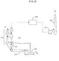
- a cement burning facility 1 comprises a preheater 2, a calciner 3, a cement kiln 4, a clinker cooler 5 and so on, and cement raw meal R is fed to the preheater 2 from raw material supplying system not shown, and cement clinker Cl is produced through preheating in the preheater 2, calcining in the calciner 3, burning in the cement kiln 4.
- the produced clinker Cl is cooled in the clinker cooler 5 and is ground in a finishing process.
- the combustion exhaust gas processing device is disposed downstream of the cement burning facility 1, and comprises an electrostatic precipitator 6 collecting dust in the combustion exhaust gas G1 from the preheater 2; a wet dust collector 7 which collects water-soluble materials, dust, etc.
- a catalyst-poisoning-substance stripper in the combustion exhaust gas G2 discharged from the electrostatic precipitator 6 and functions as a catalyst-poisoning-substance stripper; a sodium hypochlorite generator 9 which supplies sodium hypochlorite to the wet dust collector 7; a heat exchanger 10 and a heater 11 for heating beforehand combustion exhaust gas G3 which passed the wet dust collector 7; a catalyst device 12 removing NOx and persistent organic pollutants such as dioxin in the preheated combustion exhaust gas G4; a solid-liquid separator 16 which carries out solid-liquid separation of the slurry S discharged from the wet dust collector 7; and a mercury adsorbing tower 17 which adsorbs mercury in the fluid separated by the solid-liquid separator 16.
- the electrostatic precipitator 6 is installed to collect dust in the combustion exhaust gas G1 from a preheater 2. It is possible to dispose a bag filter in place of the electrostatic precipitator 6, and both of them can be installed together.
- the wet dust collector 7 is installed to collect water-soluble materials and dust in the combustion exhaust gas G2 which passed the electrostatic precipitator 6, and the wet dust collector 7 removes dust, sulfuric acid mist, hydrogen chloride (HCl), mercury (Hg), etc as catalyst-poisoning substances which have big effect on the life of the latter catalyst device 12.
- a mixing scrubber is characterized by having arranged two or more diffusers in a cylindrical body, and the mixing scrubber gives turning to the flow of gas and fluid, while the gas and fluid move with a countercurrent or concurrent into the cylinder, and is a device to contact gas and fluid with each other for reaction and dust collection.
- gas and fluid are made concurrent, and the diffusers, which give a right wheel to this flow, and the diffusers, which give a left right wheel to this flow, are arranged by turns.
- the residence time of the combustion exhaust gas of the wet dust collector 7 is set between 1 second and 10 seconds.
- a circulating liquid tank 7a Under the wet dust collector 7, a circulating liquid tank 7a is arranged, and a pump 8 is disposed between the wet dust collector 7 and the circulating liquid tank 7a, and the slurry generated by the wet dust collector 7 can be circulated through the circulating liquid tank 7a and the pump 8.
- the sodium hypochlorite generator 9 is disposed to supply sodium hypochlorite to the wet dust collector 7, and it oxidizes the mercury contained in the combustion exhaust gas G2 with the sodium hypochlorite. It is desirable to use an in-line-polarity-transformation type for the sodium hypochlorite generator 9. This type of generator directly electrolyzes in treated water without salt water.
- the heat exchanger 10 performs the heat exchange of the combustion exhaust gas G3 discharged from the circulating liquid tank 7a, and the combustion exhaust gas G5 discharged from the catalyst device 12. It is desirable to use a Ljungstrom (trademark)-type heat exchanger (made by ALSTOM K.K.) for this heat exchanger 10.
- the Ljungstrom-type heat exchanger heats a heat reservoir directly in heat side gas, and heated gas is also directly warmed.
- the heat exchange element is prepared, in the core of casing of a body, a disc-shaped heat exchange element pivotally supported, and the heat exchange element has radially many wave steel plate that are mutually laminated and has a clearance mutually, and a heat exchange is performed by passing the combustion exhaust gas G3 discharged from the circulating liquid tank 7a, and the combustion exhaust gas G5 discharged from the catalyst device 12 in the clearance.
- the heater 11 is installed to heat the combustion exhaust gas G4 discharged from the heat exchanger 10 using the steam ST generated by remaining heat or the like in the plant in which the cement burning facility 1 is installed.
- the reason why the combustion exhaust gas G4 is heated is to more effectively perform denitration and decompose persistent organic pollutants such as dioxins.
- ammonia (NHa) used as a reducing agent with the latter catalyst device 12 is added on the entrance side of the heater 11.
- ammonia used as a reducing agent with the latter catalyst device 12 is added on the entrance side of the heater 11.
- ammonia used as a reducing agent with the latter catalyst device 12 is added on the entrance side of the heater 11.
- ammonia used as a reducing agent with the latter catalyst device 12 is added on the entrance side of the heater 11.
- ammonia used as a reducing agent with the latter catalyst device 12 is added on the entrance side of the heater 11.
- ammonia used as a reducing agent with the latter catalyst device 12 is added on the entrance side of the heater 11.
- the catalyst device 12 is installed to decompose and remove NOx and persistent organic pollutants, etc. in the combustion exhaust gas G4 that passed the heat exchanger 10. By forming this catalyst device 12 in the shape of a honeycomb, even when processing a large amount of combustion exhaust gas G4, it can constitute comparatively small.
- the catalyst used with the catalyst device 12 is explained in detail.
- the catalyst used for the usual exhaust gas treatment can be used, for example, a NOx removal catalyst for exhaust gas can also be used.
- a titanium-vanadium catalyst as an oxide catalyst is used upstream, and a platinum or a palladium catalyst or the like as a noble-metal catalyst is used downstream.
- a titanium-vanadium catalyst means the catalyst that makes titanium (Ti) and vanadium (V) indispensable. This catalyst exhibits a high function in decomposition clearance of a volatile organic compound as a harmful substance, while having the high decomposition activity (denitration activity) of NOx as a harmful substance.
- one or more sorts of metallic oxides selected from tungsten (W), molybdenum (Mo), silicon (Si), zirconia (Zr) can be used collectively.
- the independent oxide of Ti it is using still more preferably one or more sorts selected from titanium (Ti), silicon (Si) and zirconia (Zr) of metallic oxides, and two element-system multiple oxide of Ti and Si or two element-system multiple oxide of Ti and Zr is especially more desirable.
- the content in particular of the titanium (Ti) occupied in a titanium-vanadium catalyst is not limited, it is desirable, as an oxide reduced mass ratio to the total mass of a titanium-vanadium catalyst, 15-9.9 mass percent, for example, and 30-99 mass percent is more desirable. Sufficient effect may not be acquired by lowering of a specific surface area etc. in case of under 15 mass percent, and on the other hand, when 99.9 mass percent is exceeded, there is a possibility that sufficient catalytic activity may not be acquired.
- the rate in particular of at least one sort of metallic oxides chosen from the group which consists of vanadium (V), tungsten (W) and molybdenum (Mo) is not limited, it is, as an oxide reduced mass ratio to the total amount of a titanium-vanadium catalyst, 0.5-30 mass percent, and preferably 1-20 mass percent.
- V vanadium
- W tungsten
- Mo molybdenum
- an oxidation catalyst with at least one sort of noble metals chosen from platinum, palladium, rhodium and ruthenium and/or the compound of those is used.
- This catalyst can use a carrier suitably, for example, platinum etc. for a carrier, and alumina, silica, zirconia, titania, vanadia, ferrous oxide, manganese oxide, and these mixtures and multiple oxides can be used as a carrier.
- the titanium-vanadium catalyst can also be used as a carrier.
- a noble-metal catalyst preparation of a noble-metal catalyst is shown below.
- the salts of these noble metals, or its solution can be added, for example.
- making it impregnated can perform support of at least one sort of noble metals chosen from platinum, palladium, rhodium and ruthenium and/or its compound component, and this impregnating support is more desirable.
- noble metal and/or its compound to a carrier is 0.001 to 5 mass percent, more preferably 0.05-2.5 mass percent. If it is under 0.001 mass percent, the decomposition activity of a volatile organic compound becomes low, and when it exceeds 5 mass percent, the activity corresponding to the addition is not acquired and not desirable.
- alumina, silica, silica alumina, cordierite, titania, stainless steel, metal, etc. may be supported and used for the carrier of plainer shape, the shape of a corrugated plate, tabular shape, the shape of a net, the shape of a honeycomb, the shape of a column and cylindrical shape.
- the binary system multiple oxide containing titanium oxide and one or more sorts chosen from silicon (Si) and zirconium (Zr), titanium oxide, or the mixtures of titanium oxide and one or more sorts of oxide chosen from silicon (Si) and zirconium (Zr) is made into a titanium component; to the powder of this titanium component, the water solution that includes the source of vanadium is added with the organic or inorganic forming assistant generally used at this kind of fabrication; then it is heated while being mixed and kneaded to evaporate its moisture and to be pasty to an extent that extrusion is possible; it is fabricated with an extruder in the shape of a honeycomb etc.; and it is dried and calcined at an elevated temperature (preferably 200-600°C) in the air.
- an elevated temperature preferably 200-600°C
- the catalysis by fabricating the titanium component in forms such as a spherical pellet, a cylindrical pellet or a cancellous honeycomb beforehand; calcinating the titanium component; and carrying out impregnating support of the water solution including the source of vanadium. Further, it is possible to prepare the catalysis by directly kneading the powder of the titanium component to the powder of vanadium oxide.
- the catalyst used with the catalyst device 12 is not limited in particular for BET surface area, it is desirable to be 20-300m 2 /g, more preferably 30-250m 2 /g, and the catalyst with such BET surface area is high in activity, and excellent in durability, Moreover, when the pore volume by a method of mercury penetration is too small, the catalytic activity and durability for clearance of the harmful substances of the object of this invention such as NOx, persistent organic pollutants, a volatile organic compound and CO become low, and when the mercury penetration is too large, the strength of the catalyst will fall, so that the pore volume of the catalyst is preferably between 0.3 to 0.55 cc/g.
- the shape of the above-mentioned oxide catalyst and the noble-metal catalyst is not limited in particular, and it can be used as a preferable form of the shape of a honeycomb, plainer shape, the shape of a net, the shape of a column, cylindrical shape and so on.
- the catalyst temperature of the catalyst device from which the target harmful substance is removed 140°C or more are desirable, and 180°C or more is more preferable. It is because when the temperature of the catalyst is less than 140°C, denitration efficiency and the decomposition efficiency of a volatile organic compound become low.
- the space velocity of the exhaust gas in the above-mentioned oxide catalyst and the noble-metal catalyst is not restricted in particular, it is preferably 100-100000Hr -1 and more preferably 200-50000Hr -1 .
- the space velocity is less than 100Hr -1 , a device becomes large too much, which becomes inefficient, and on the other hand, when 100000Hr -1 is exceeded, there is an inclination for the denitration efficiency and the decomposition efficiency of a volatile organic compound to fall.
- the solid-liquid separator 16 is installed to carry out solid-liquid separation of the slurry discharged from the wet dust collector 7, and a filter press or the like may be used for it.
- the mercury-adsorbing tower 17 is installed to adsorb mercury in the fluid separated with the solid-liquid separator 16. A part of the wastewater W of the mercury-adsorbing tower 17 is supplied to the sodium hypochlorite generator 9, and it is used to generate sodium hypochlorite.
- the combustion exhaust gas G1 from the cement kiln 4 desulfurized in the preheater 2 is introduced into the electrostatic precipitator 6, and dust in the combustion exhaust gas G1 is collected.
- the combustion exhaust gas G2 which passed the electrostatic precipitator 6 is introduced into the wet dust collector 7, and the water-soluble materials and dust in the combustion exhaust gas G2 are collected to remove catalyst-poisoning substances which have big effect on the life of the latter catalyst device 12, such as dust, sulfuric acid mist, hydrogen chloride (HCl) and mercury (Hg).
- the temperature of the combustion exhaust gas G2 is controlled to become approximately 100°C.
- the slurry generated at the wet dust collector 7 circulates through the circulating liquid tank 7a and the pump 8, which allows the contact between the combustion exhaust gas G2 and the fluid to be performed sufficiently, and allows the oxidation of mercury and the like by the sodium hypochlorite supplied from the sodium hypochlorite generator 9 and the recovery of water-soluble materials and dust to be performed efficiently.
- the wet dust collector 7 while circulating water, a part of the water is extracted so as to be supplied to the solid-liquid separator 16, but this circulating water is discharged to the grade that does not pose a problem.
- the combustion exhaust gas G3 of approximately 80 °C from which catalyst-poisoning substances, such as water-soluble materials and dust, are removed, is introduced from the circulating liquid tank 7a to the heat exchanger 10 and the heater 11, and is heated there.
- the combustion exhaust gas G3 is heated because it is desirable to perform denitration of the combustion exhaust gas G4 and decomposition of persistent organic pollutants in the catalyst device 12 at 140-500°C as mentioned above, and when the decomposition performance and the durability of a catalyst are taken into consideration, it is desirable to decompose at approximately 230-270°C.
- the combustion exhaust gas G5 discharged from the catalyst device 12 is used for the heat source of the heat exchanger 10.
- the heat exchange of the combustion exhaust gas G5 discharged from the catalyst device 12 is carried out with the combustion exhaust gas G3 introduced from the wet dust collector 7 in the heat exchanger 10. Since the temperature increase of the combustion exhaust gas G4 cannot fully be performed only by the heat exchange in the heat exchanger 10, auxiliary steam ST is introduced into the heater 11, and the combustion exhaust gas G4 is heated further.
- the steam with remaining heat or the like in the plant in which the cement burning facility 1 is installed can be used for this auxiliary steam ST.
- ammonia (NH 3 ) as a denitration agent used in the catalyst device 12 is injected into the entrance side of the heater 11.
- the injection rate of the ammonia is controlled according to the NOx concentration of the combustion exhaust gas G1 discharged from the preheater 2.
- ammonia can be added to a portion between the outlet of the wet dust collector 7 and the inlet of the catalyst device 12, where the mixing effect is available other than the entrance side of the heater 11. It is possible to add aqueous ammonia to the combustion exhaust gas after preheating with the heater 11 and to allow the gas to pass the catalyst device 12.
- the combustion exhaust gas G4 is supplied to the catalyst device 12, and NOx, persistent organic pollutants, a volatile organic compound, CO, etc. are removed through decomposition and so on.
- the temperature in the catalyst device 12 is controlled at 140-500°C preferably 230-270°C which is suitable for denitration of combustion exhaust gas G and decomposition of persistent organic pollutants.
- the heat exchanger 10 since the heat exchanger 10 is arranged, it is possible to control the temperature in the catalyst device 12 highly, and raising the operating temperature of the catalyst device 12 as much as possible allows the efficiency of the catalyst device 12 to rise, which can reduce the amount of the catalyst.
- the combustion exhaust gas G5 from the catalyst device 12 is emitted to the air through the heat exchanger 10, the fan 14 and the stack 15.
- the temperature of the combustion exhaust gas G6 becomes approximately 110°C due to the recovery of its remaining heat.
- the slurry S discharged from the circulating liquid tank 7a is solid-liquid separated by the solid-liquid separator 16, and the cake C separated is used as a cement raw material.
- mercury in the fluid separated by the solid-liquid separator 16 dissolves in water as a chloro-complex ion (HgCl 4 2- ), and this ion is adsorbed by the mercury-adsorbing tower 17.
- HgCl 4 2- chloro-complex ion
- the mercury-adsorbing tower 17 As to the mercury, it is possible to solid-separate as (HgCl 2 ), and then ion may be adsorbed and separated.
- Some wastewater W from which mercury is removed is supplied to the sodium hypochlorite generator 9, others can be processed out of the system or it can also use them for the cooling of the combustion exhaust gas G1 of the cement kiln 4, a water spray of a cement raw material mill or a dryer for a cement raw material and so on.
- each harmful-substance-elimination factor using the combustion-exhaust-gas processing device with the construction shown in Fig. 1 and a titanium-vanadium catalyst for the catalyst device 12, is shown in Table 1.
- the combustion-exhaust-gas temperature at the inlet of the catalyst device 12 was 180°C, and space velocity (SV value) was set to be 5060h -1 .
- the harmful-substance-elimination factor is computed using the concentration of each harmful substance of the outlet of the electrostatic precipitator 6, and the concentration of each harmful substance of the outlet of the catalyst device 12. That is, the rate that the catalyst device 12 removes each harmful substance in the outlet of the electrostatic precipitator 6 is shown.
- each harmful-substance-elimination factor using the combustion-exhaust-gas processing device with the construction shown in Fig. 1 and at the time of arranging a titanium-vanadium catalyst (oxide catalyst) upstream, and platinum catalyst (noble-metal catalyst) downstream at the catalyst device 12, is shown in Table 2.
- Embodiment 2 Comparative example 1 Gas temperature 180°C 210°C 250°C 180°C 210°C 250°C Harmful substances Eliminaition factor (%) Eliminaition factor (%) Nox 97 98 99 97 75 20 Persistent organic pollutants 89 92 93 89 92 93 Mercury (Hg) 97 97 97 97 97 97 97 97 97 Smoke dust 90 90 90 90 90 90 Ammonia (NH3) 97 98 99 97 98 99 Odor 95 98 99 95 85 70 PCB 95 98 99 95 98 99 CO 98 99 99 99 98 99 99 99 Embodiment 2 ⁇ Upstream: Oxidation catalyst, Downstream: Noble-metal catalyst Comparative example 1 ⁇ Upstream: Noble-metal catalyst,Downstream:Oxidation catalyst
- independently installed oxide catalyst in the upstream is preferably effective. Moreover, further excellent effect is acquired by making it the two steps of catalyst system with upstream oxide catalyst and downstream noble-metal catalyst, and it is still more desirable.
- the decomposition clearance of NOx, a volatile organic compound, and persistent organic pollutants, which are the harmful substances in exhaust gas is attained.
- the downstream is equipped with a noble-metal catalyst to form a two-step catalyst system, the decomposition clearance of NOx, a volatile organic compound, and persistent organic pollutants, which are the harmful substances in exhaust gas, is attained; the decomposition clearance of CO is attained simultaneously; and the decomposition performance of the volatile organic compound is also improved, resulting in further excellent effect.
- each harmful-substance-elimination factor using the combustion-exhaust-gas processing device with the construction shown in Fig. 1 and the time of arranging a titanium-vanadium catalyst (oxide catalyst) upstream, and platinum catalyst (noble-metal catalyst) downstream at the catalyst device 12, is shown in Table 3.
- the temperature of combustion exhaust gas at the inlet of the catalyst device 12 was 180°C.
- Space velocity (SV value) was set to be 5,060h -1 for the titanium-vanadium catalyst, and 24,200h -1 for the platinum catalyst.
- SV value space velocity
- the mesh size (bore diameter) of the catalyst a 2.9mm honeycomb catalyst for the titanium-vanadium catalyst was used and a 1.77mm honeycomb catalyst for the platinum catalyst.
- the reducing agent (NH 3 gas) was sprayed upstream of the catalyst device, and set the mole ratio of NOx and NH 3 was set to be 1.
- the mesh size (bore diameter) of a catalyst means, as shown in Fig.
- the wet dust collector 7 which adds sodium hypochlorite to the combustion exhaust gas G2 was used as a catalyst-poisoning-substance stripper
- a bag filter for which dust is collected while blowing activated carbon into the combustion exhaust gas G2 can also be used. With the activated carbon, dust, mercury and SOx are efficiently removable.
Landscapes
- Engineering & Computer Science (AREA)
- Chemical & Material Sciences (AREA)
- Environmental & Geological Engineering (AREA)
- Health & Medical Sciences (AREA)
- Biomedical Technology (AREA)
- Analytical Chemistry (AREA)
- General Chemical & Material Sciences (AREA)
- Oil, Petroleum & Natural Gas (AREA)
- Chemical Kinetics & Catalysis (AREA)
- Ceramic Engineering (AREA)
- Mechanical Engineering (AREA)
- General Engineering & Computer Science (AREA)
- Materials Engineering (AREA)
- Structural Engineering (AREA)
- Organic Chemistry (AREA)
- Physics & Mathematics (AREA)
- Thermal Sciences (AREA)
- Toxicology (AREA)
- Public Health (AREA)
- Exhaust Gas Treatment By Means Of Catalyst (AREA)
- Catalysts (AREA)
- Treating Waste Gases (AREA)
- Curing Cements, Concrete, And Artificial Stone (AREA)
Applications Claiming Priority (2)
| Application Number | Priority Date | Filing Date | Title |
|---|---|---|---|
| JP2005001496 | 2005-01-06 | ||
| PCT/JP2005/023859 WO2006073083A1 (ja) | 2005-01-06 | 2005-12-27 | セメントキルン燃焼排ガス処理装置及び処理方法 |
Publications (2)
| Publication Number | Publication Date |
|---|---|
| EP1842836A1 true EP1842836A1 (de) | 2007-10-10 |
| EP1842836A4 EP1842836A4 (de) | 2013-12-11 |
Family
ID=36647565
Family Applications (1)
| Application Number | Title | Priority Date | Filing Date |
|---|---|---|---|
| EP05822629.1A Withdrawn EP1842836A4 (de) | 2005-01-06 | 2005-12-27 | Vorrichtung und verfahren zur verarbeitung von zementofenverbrennungsabgas |
Country Status (7)
| Country | Link |
|---|---|
| US (2) | US8470273B2 (de) |
| EP (1) | EP1842836A4 (de) |
| JP (1) | JP5140277B2 (de) |
| KR (1) | KR101207958B1 (de) |
| CN (1) | CN101098835A (de) |
| TW (1) | TWI410270B (de) |
| WO (1) | WO2006073083A1 (de) |
Cited By (12)
| Publication number | Priority date | Publication date | Assignee | Title |
|---|---|---|---|---|
| WO2009108983A1 (de) * | 2008-03-06 | 2009-09-11 | Scheuch Gmbh | Anlage zur reinigung der rauchgase eines ofens |
| EP2248574A1 (de) * | 2008-02-28 | 2010-11-10 | Mitsubishi Heavy Industries, Ltd. | Verfahren und vorrichtung zur verarbeitung von abgasen |
| WO2010136396A1 (de) * | 2009-05-27 | 2010-12-02 | Polysius Ag | Verfahren und anlage zur wärmebehandlung von feinkörnigem material |
| WO2011063905A1 (de) * | 2009-11-26 | 2011-06-03 | Chemisch Thermische Prozesstechnik Gmbh | Verfahren und vorrichtung zur reinigung von abgasen mittels regenerativer thermischer nachverbrennung |
| EP2583286A4 (de) * | 2010-07-02 | 2014-05-21 | Mercutek Llc | Verminderung der von einem zementofenabgas ausgehenden umweltverschmutzung |
| CN103962005A (zh) * | 2014-05-08 | 2014-08-06 | 南通亚泰船舶工程有限公司 | 一种船用选择性脱硝scr催化剂的快速预热工艺及系统 |
| US8876967B2 (en) | 2010-08-18 | 2014-11-04 | Mercutek Llc | Cement kiln dust treatment system and method |
| WO2015189176A1 (de) * | 2014-06-10 | 2015-12-17 | Elex Cemcat Ag | Verfahren zur abgasbehandlung und anlage mit einer abgasbehandlungsvorrichtung |
| WO2016128545A1 (de) * | 2015-02-13 | 2016-08-18 | Elex Cemcat Ag | Verfahren zur reinigung von abgasen bei der thermischen aufarbeitung von mineralstoffen |
| WO2016173785A1 (de) * | 2015-04-30 | 2016-11-03 | Dürr Systems Ag | Reinigungsvorrichtung, kalzinieranlage und verfahren zum reinigen eines rohgasstroms |
| US9884311B2 (en) | 2012-03-14 | 2018-02-06 | Mercutek Llc | Activated carbon and coal combustion residue treatment system and method |
| EP3294441A4 (de) * | 2015-05-12 | 2018-12-05 | FLSmidth A/S | Nox-reduktionsverfahren in einem zementofenfertigungssystem |
Families Citing this family (39)
| Publication number | Priority date | Publication date | Assignee | Title |
|---|---|---|---|---|
| WO2004052801A1 (ja) * | 2002-12-11 | 2004-06-24 | Taiheiyo Cement Corporation | セメントキルン塩素・硫黄バイパスシステム |
| JP5125629B2 (ja) * | 2008-03-07 | 2013-01-23 | 住友大阪セメント株式会社 | セメント製造設備におけるタリウムの回収方法及び回収装置 |
| TW200940158A (en) * | 2008-03-07 | 2009-10-01 | Taiheiyo Cement Corp | Cement kiln extracted gas treating system and treating method |
| JP2009298677A (ja) * | 2008-06-17 | 2009-12-24 | Taiheiyo Cement Corp | セメントキルン抽気ガスの処理システム及び処理方法 |
| JP5522740B2 (ja) * | 2008-06-17 | 2014-06-18 | 太平洋セメント株式会社 | セメントキルン排ガスの処理装置及び処理方法 |
| JP5068698B2 (ja) * | 2008-06-19 | 2012-11-07 | 太平洋セメント株式会社 | セメントキルン抽気ガスの処理システム及び処理方法 |
| US7972419B2 (en) * | 2008-08-07 | 2011-07-05 | Flsmidth A/S | Apparatus and method for reducing emissions resulting from raw meal grinding |
| JP5407262B2 (ja) * | 2008-10-08 | 2014-02-05 | 三菱マテリアル株式会社 | セメント焼成設備の排ガス処理方法および処理システム |
| DK2389997T3 (en) * | 2009-01-22 | 2019-03-11 | Taiheiyo Cement Corp | Device for removal of heavy metals and cement production system |
| CN101488015B (zh) * | 2009-02-13 | 2011-01-05 | 温平 | 干法水泥生产线节能减排实时量化的监控方法 |
| KR100975535B1 (ko) * | 2009-04-21 | 2010-08-13 | 김흥규 | 촉매 산화 시스템 및 그 장치의 촉매 산화 방법 |
| JP5528743B2 (ja) * | 2009-09-02 | 2014-06-25 | 太平洋セメント株式会社 | セメントキルン抽気ガスの処理システム及び処理方法 |
| JP5582569B2 (ja) * | 2010-09-09 | 2014-09-03 | 太平洋セメント株式会社 | セメントキルン排ガスからの回収水の利用システム及び利用方法 |
| KR101527102B1 (ko) * | 2010-11-26 | 2015-06-10 | (주)바이오니아 | 유해물질 제거 장치 |
| DE102011000564B4 (de) * | 2011-02-08 | 2013-05-02 | Elex Cemcat Ag | Verfahren und Anlage zur Herstellung von Zementklinker |
| US20140017139A1 (en) * | 2011-03-24 | 2014-01-16 | Medclair AB | Apparatus for decomposition of nitrous oxide in a gas stream |
| WO2013019393A1 (en) * | 2011-07-29 | 2013-02-07 | Flsmidth A/S | Pollution control system for kiln exhaust |
| JP5877578B2 (ja) * | 2011-10-24 | 2016-03-08 | 太平洋セメント株式会社 | 燃焼排ガス処理装置及び処理方法 |
| JP5912638B2 (ja) * | 2012-02-20 | 2016-04-27 | 太平洋セメント株式会社 | セメントキルン排ガス処理装置及び処理方法 |
| US8591844B1 (en) * | 2012-05-17 | 2013-11-26 | Fluor Technologies Corporation | Start up catalyst heating |
| CN102961954B (zh) * | 2012-11-05 | 2014-01-22 | 浙江浙大海元环境科技有限公司 | 一种水泥窑炉烟气NOx减排装置 |
| JP6066193B2 (ja) * | 2013-03-14 | 2017-01-25 | 太平洋セメント株式会社 | セメントキルン排ガスの処理装置及び処理方法 |
| KR101661601B1 (ko) * | 2013-11-20 | 2016-09-30 | 삼성엔지니어링 주식회사 | 폐가스로부터의 voc 제거 및 악취 개선 장치 |
| DE102014100896A1 (de) * | 2014-01-27 | 2015-07-30 | Thyssenkrupp Ag | Verfahren zur Wärmebehandlung eines Stoffstroms und zur Reinigung von dabei entstehenden Abgasen |
| AT14170U1 (de) * | 2014-05-27 | 2015-05-15 | Scheuch Gmbh | Vorrichtung zur Herstellung von Zementklinker |
| JP6344850B2 (ja) * | 2014-07-23 | 2018-06-20 | 太平洋セメント株式会社 | セメントキルン排ガス処理装置及び処理方法 |
| CN104324709B (zh) * | 2014-10-22 | 2016-08-31 | 胡宗伟 | Voc吸附用活性炭的再生方法及专用活化剂 |
| EP3250661A4 (de) * | 2015-01-30 | 2018-09-12 | SCB International Holdings, LLC | Behandlung von zementofenbrennstoff |
| CN106334432A (zh) * | 2015-07-14 | 2017-01-18 | 上海三卿环保科技有限公司 | 一种利用脱硫脱硝循环液激活氧化剂的装置及工艺方法 |
| WO2018131277A1 (ja) * | 2017-01-11 | 2018-07-19 | 太平洋エンジニアリング株式会社 | セメントキルン排ガスの水銀低減方法及びその装置 |
| CN107551803A (zh) * | 2017-09-08 | 2018-01-09 | 齐鲁工业大学 | 一种利用玻璃窑炉蓄热室实现玻璃窑炉废气脱硝 |
| US11014044B2 (en) * | 2018-09-03 | 2021-05-25 | South China Institute Of Environmental Science, Mee | Waste gas purification system and method |
| US11680013B2 (en) | 2019-05-13 | 2023-06-20 | Carmeuse Lime, Inc. | Calciner using recirculated gases |
| CN111925848B (zh) * | 2020-07-10 | 2021-10-15 | 中国石油集团工程股份有限公司 | 一种羰基硫高效脱除溶剂及其制备方法 |
| WO2023053218A1 (ja) | 2021-09-28 | 2023-04-06 | 三菱重工業株式会社 | 脱硝装置 |
| CN114135882A (zh) * | 2021-11-02 | 2022-03-04 | 南京鑫天恒环保技术研究院有限公司 | 一种吸附浓缩耦合催化燃烧废气处理设备 |
| CN114405045B (zh) * | 2022-01-25 | 2023-03-21 | 安徽碳鑫科技有限公司 | 一种稳定塔尾气处理方式 |
| JP7327559B1 (ja) | 2022-03-28 | 2023-08-16 | 住友大阪セメント株式会社 | セメント排ガス中の二酸化窒素処理方法 |
| TWI796206B (zh) * | 2022-04-18 | 2023-03-11 | 凱德利斯特國際有限公司 | 智慧型多功能環保裝置 |
Citations (5)
| Publication number | Priority date | Publication date | Assignee | Title |
|---|---|---|---|---|
| EP0826408A1 (de) * | 1996-08-31 | 1998-03-04 | Katalysatorenwerke Hüls GmbH | Verfahren zur reduktiven Zerstörung von Stickstoffoxiden in Staub-haltigen Abgasen aus Anlagen zur Herstellung von Zement |
| WO1998025689A1 (en) * | 1996-12-09 | 1998-06-18 | Imperial Chemical Industries Plc | Process for removing chlorine from gas stream |
| JP2003251200A (ja) * | 2002-02-28 | 2003-09-09 | Suzuki Motor Corp | 排気ガス浄化触媒のアルミナ、排気ガス浄化触媒、及びこれらの製造方法 |
| US20040166043A1 (en) * | 2003-02-24 | 2004-08-26 | Vandine Robert W. | Gas scrubbing reagent and methods for using same |
| DE10316784A1 (de) * | 2003-04-11 | 2004-10-28 | Polysius Ag | Verfahren und Anlage zur NO/CO-Minderung von staubhaltigen Abgasen |
Family Cites Families (18)
| Publication number | Priority date | Publication date | Assignee | Title |
|---|---|---|---|---|
| JPS5344472A (en) * | 1976-10-05 | 1978-04-21 | Sumitomo Cement Co | Method of reducing nitrogen oxides from cement sintering furnace exhaust gases |
| JPS5386720A (en) * | 1976-11-30 | 1978-07-31 | Mitsubishi Mining & Cement Co | Method of removing nitrogen oxides from combustion exhaust gas from calcinating furnace of cement clinker |
| US4366133A (en) * | 1981-06-01 | 1982-12-28 | Combustion Engineering, Inc. | Process for limiting chloride buildup in SO2 scrubber slurry |
| US5120695A (en) * | 1989-07-28 | 1992-06-09 | Degusaa Aktiengesellschaft (Degussa Ag) | Catalyst for purifying exhaust gases from internal combustion engines and gas turbines operated at above the stoichiometric ratio |
| JPH0714459B2 (ja) * | 1990-09-06 | 1995-02-22 | 正勝 平岡 | 排ガスの処理方法 |
| JP2962067B2 (ja) | 1992-04-10 | 1999-10-12 | 松下電器産業株式会社 | ディジタルvtrの信号処理装置 |
| JP3354587B2 (ja) * | 1992-04-16 | 2002-12-09 | バブコック日立株式会社 | 触媒構造体およびその製造方法 |
| JP3221147B2 (ja) | 1993-03-04 | 2001-10-22 | 株式会社村田製作所 | 圧電磁器 |
| JP3285692B2 (ja) * | 1994-01-26 | 2002-05-27 | 日立造船株式会社 | 焼却炉における飛灰処理装置 |
| JP3480596B2 (ja) * | 1994-05-10 | 2003-12-22 | 三井鉱山株式会社 | 乾式脱硫脱硝プロセス |
| CH692181A5 (de) * | 1995-09-08 | 2002-03-15 | Elex Ag | Rauchgasreinigungsanlage. |
| EP1346759A3 (de) * | 1998-02-23 | 2004-08-04 | Mitsubishi Heavy Industries, Ltd. | Verfahren zur Rauchgasbehandlung |
| US6197268B1 (en) * | 1999-07-02 | 2001-03-06 | The Boc Group, Inc. | Reduction of toxic substances in waste gas emissions |
| JP2001198434A (ja) * | 2000-01-18 | 2001-07-24 | Mitsubishi Heavy Ind Ltd | 排ガス中の水銀処理方法および排ガスの処理システム |
| JP2002219335A (ja) | 2001-01-30 | 2002-08-06 | Babcock Hitachi Kk | 排ガス処理装置 |
| JP4831801B2 (ja) * | 2001-08-09 | 2011-12-07 | 三菱重工業株式会社 | 排ガスの水銀除去方法及び装置 |
| US7799297B2 (en) * | 2003-07-10 | 2010-09-21 | Taiheiyo Cement Corporation | Device and method for processing combustion exhaust gas |
| US7264784B2 (en) * | 2003-10-22 | 2007-09-04 | Nippon Shokubai Co., Ltd. | Method for treating exhaust gas |
-
2005
- 2005-12-27 WO PCT/JP2005/023859 patent/WO2006073083A1/ja active Application Filing
- 2005-12-27 KR KR1020077014449A patent/KR101207958B1/ko not_active IP Right Cessation
- 2005-12-27 EP EP05822629.1A patent/EP1842836A4/de not_active Withdrawn
- 2005-12-27 CN CNA2005800461238A patent/CN101098835A/zh active Pending
- 2005-12-27 US US11/794,820 patent/US8470273B2/en not_active Expired - Fee Related
- 2005-12-27 JP JP2006550784A patent/JP5140277B2/ja not_active Expired - Fee Related
- 2005-12-29 TW TW094147211A patent/TWI410270B/zh not_active IP Right Cessation
-
2013
- 2013-05-15 US US13/895,211 patent/US8765066B2/en not_active Expired - Fee Related
Patent Citations (5)
| Publication number | Priority date | Publication date | Assignee | Title |
|---|---|---|---|---|
| EP0826408A1 (de) * | 1996-08-31 | 1998-03-04 | Katalysatorenwerke Hüls GmbH | Verfahren zur reduktiven Zerstörung von Stickstoffoxiden in Staub-haltigen Abgasen aus Anlagen zur Herstellung von Zement |
| WO1998025689A1 (en) * | 1996-12-09 | 1998-06-18 | Imperial Chemical Industries Plc | Process for removing chlorine from gas stream |
| JP2003251200A (ja) * | 2002-02-28 | 2003-09-09 | Suzuki Motor Corp | 排気ガス浄化触媒のアルミナ、排気ガス浄化触媒、及びこれらの製造方法 |
| US20040166043A1 (en) * | 2003-02-24 | 2004-08-26 | Vandine Robert W. | Gas scrubbing reagent and methods for using same |
| DE10316784A1 (de) * | 2003-04-11 | 2004-10-28 | Polysius Ag | Verfahren und Anlage zur NO/CO-Minderung von staubhaltigen Abgasen |
Non-Patent Citations (1)
| Title |
|---|
| See also references of WO2006073083A1 * |
Cited By (25)
| Publication number | Priority date | Publication date | Assignee | Title |
|---|---|---|---|---|
| EP2248574A1 (de) * | 2008-02-28 | 2010-11-10 | Mitsubishi Heavy Industries, Ltd. | Verfahren und vorrichtung zur verarbeitung von abgasen |
| EP2248574A4 (de) * | 2008-02-28 | 2012-02-22 | Mitsubishi Heavy Ind Ltd | Verfahren und vorrichtung zur verarbeitung von abgasen |
| US8420034B2 (en) | 2008-02-28 | 2013-04-16 | Mitsubishi Heavy Industries, Ltd. | Method and apparatus for treating exhaust gas |
| WO2009108983A1 (de) * | 2008-03-06 | 2009-09-11 | Scheuch Gmbh | Anlage zur reinigung der rauchgase eines ofens |
| WO2010136396A1 (de) * | 2009-05-27 | 2010-12-02 | Polysius Ag | Verfahren und anlage zur wärmebehandlung von feinkörnigem material |
| CN102762275B (zh) * | 2009-11-26 | 2015-06-10 | 化学热处理技术股份有限公司 | 用于净化废气的方法和装置 |
| WO2011063905A1 (de) * | 2009-11-26 | 2011-06-03 | Chemisch Thermische Prozesstechnik Gmbh | Verfahren und vorrichtung zur reinigung von abgasen mittels regenerativer thermischer nachverbrennung |
| CN102762275A (zh) * | 2009-11-26 | 2012-10-31 | 化学热处理技术股份有限公司 | 用于净化废气的方法和装置 |
| US9272240B2 (en) | 2009-11-26 | 2016-03-01 | Chemisch Thermische Prozesstechnik Gmbh | Method and device for purifying exhaust gases |
| DE102009055942C5 (de) * | 2009-11-26 | 2015-12-17 | Chemisch-Thermische Prozesstechnik Gmbh | Verfahren und Vorrichtung zur Reinigung von Abgasen |
| US9498747B2 (en) | 2010-07-02 | 2016-11-22 | Mercutek Llc | Cement kiln exhaust gas pollution reduction |
| EP2583286A4 (de) * | 2010-07-02 | 2014-05-21 | Mercutek Llc | Verminderung der von einem zementofenabgas ausgehenden umweltverschmutzung |
| US11285440B2 (en) | 2010-07-02 | 2022-03-29 | Mercury Capture Intellectual Property, Llc | Exhaust gas pollution reduction |
| US10307711B2 (en) | 2010-07-02 | 2019-06-04 | Mercury Capture Intellectual Property, Llc | Cement kiln exhaust gas pollution reduction |
| US10130912B2 (en) | 2010-07-02 | 2018-11-20 | Mercury Capture Intellectual Property, Llc | Cement kiln exhaust gas pollution reduction |
| US8876967B2 (en) | 2010-08-18 | 2014-11-04 | Mercutek Llc | Cement kiln dust treatment system and method |
| US9873636B2 (en) | 2010-08-18 | 2018-01-23 | Mercutek Llc | Cement kiln dust treatment system and method |
| US9493376B2 (en) | 2010-08-18 | 2016-11-15 | Mercutek Llc | Cement kiln dust treatment system and method |
| US9884311B2 (en) | 2012-03-14 | 2018-02-06 | Mercutek Llc | Activated carbon and coal combustion residue treatment system and method |
| CN103962005B (zh) * | 2014-05-08 | 2015-09-23 | 南通亚泰工程技术有限公司 | 一种船用选择性脱硝scr催化剂的快速预热工艺及系统 |
| CN103962005A (zh) * | 2014-05-08 | 2014-08-06 | 南通亚泰船舶工程有限公司 | 一种船用选择性脱硝scr催化剂的快速预热工艺及系统 |
| WO2015189176A1 (de) * | 2014-06-10 | 2015-12-17 | Elex Cemcat Ag | Verfahren zur abgasbehandlung und anlage mit einer abgasbehandlungsvorrichtung |
| WO2016128545A1 (de) * | 2015-02-13 | 2016-08-18 | Elex Cemcat Ag | Verfahren zur reinigung von abgasen bei der thermischen aufarbeitung von mineralstoffen |
| WO2016173785A1 (de) * | 2015-04-30 | 2016-11-03 | Dürr Systems Ag | Reinigungsvorrichtung, kalzinieranlage und verfahren zum reinigen eines rohgasstroms |
| EP3294441A4 (de) * | 2015-05-12 | 2018-12-05 | FLSmidth A/S | Nox-reduktionsverfahren in einem zementofenfertigungssystem |
Also Published As
| Publication number | Publication date |
|---|---|
| TW200631646A (en) | 2006-09-16 |
| US8765066B2 (en) | 2014-07-01 |
| JPWO2006073083A1 (ja) | 2008-08-07 |
| JP5140277B2 (ja) | 2013-02-06 |
| US8470273B2 (en) | 2013-06-25 |
| WO2006073083A1 (ja) | 2006-07-13 |
| TWI410270B (zh) | 2013-10-01 |
| KR101207958B1 (ko) | 2012-12-04 |
| KR20070103369A (ko) | 2007-10-23 |
| US20130251599A1 (en) | 2013-09-26 |
| CN101098835A (zh) | 2008-01-02 |
| EP1842836A4 (de) | 2013-12-11 |
| US20090169453A1 (en) | 2009-07-02 |
Similar Documents
| Publication | Publication Date | Title |
|---|---|---|
| US8765066B2 (en) | Device and method for processing cement kiln combustion exhaust gas | |
| EP0787521B1 (de) | Verfahren und Vorrichtung zum Behandeln von Verbrennungsabgasen | |
| EP1874441B1 (de) | Katalysator zur oxidation von ammoniak für kohlebefeuerte versorgungsbetriebe | |
| JP4860076B2 (ja) | 窒素酸化物の選択的接触還元のための触媒の製造方法 | |
| EP3241602B1 (de) | Verfahren zur katalytischen oxidation von ammoniak in energieversorgungsunternehmen | |
| EP2044997B1 (de) | Vorrichtung zur entfernung einer spur einer toxischen substanz aus abgas und verfahren zu ihrem betrieb | |
| JP5051977B2 (ja) | 排ガス中微量有害物質の除去装置及びその運転方法 | |
| EP3271049B1 (de) | Katalysierter keramischer kerzenfilter und verfahren eines prozesses zur reining von abgas oder auspuffgas | |
| JP3979837B2 (ja) | ダイオキシン除去用触媒の製造方法 | |
| US10682639B2 (en) | Method for preparing a catalyst-containing ceramic filter for off-gas or exhaust gas cleaning | |
| KR101670075B1 (ko) | 선택적 촉매환원반응용 탈질촉매의 제조방법 | |
| CN109715269B (zh) | 一种在60~500℃温度范围内吸附除去气流中的氮氧化物的有害气体净化剂 | |
| EP1726565A1 (de) | Vorrichtung zur kohlenstoffmaterial- und abgasbehandlung | |
| EP1192991A2 (de) | Verfahren zur Herstellung eines Katalysators zur selektiven katalytischen Reduktion von Stickoxiden | |
| US20060178263A1 (en) | Carbon material and flue gas treatment apparatus | |
| KR100382050B1 (ko) | 배가스 내의 다이옥신 및 질소산화물 제거용 저온 촉매 및이를 이용한 연소배가스의 처리방법 | |
| KR20010017297A (ko) | 폐가스에 함유된 질소 산화물 및 다이옥신의 동시 제거방법 | |
| JP2011230043A (ja) | 窒素酸化物除去触媒及びこれを用いた窒素酸化物除去装置 |
Legal Events
| Date | Code | Title | Description |
|---|---|---|---|
| PUAI | Public reference made under article 153(3) epc to a published international application that has entered the european phase |
Free format text: ORIGINAL CODE: 0009012 |
|
| 17P | Request for examination filed |
Effective date: 20070601 |
|
| AK | Designated contracting states |
Kind code of ref document: A1 Designated state(s): CH DE DK ES FR LI |
|
| DAX | Request for extension of the european patent (deleted) | ||
| RBV | Designated contracting states (corrected) |
Designated state(s): CH DE DK ES FR LI |
|
| RBV | Designated contracting states (corrected) |
Designated state(s): CH DE DK ES FR LI |
|
| A4 | Supplementary search report drawn up and despatched |
Effective date: 20131112 |
|
| RIC1 | Information provided on ipc code assigned before grant |
Ipc: B01D 53/86 20060101ALI20131106BHEP Ipc: C04B 7/43 20060101ALI20131106BHEP Ipc: F27D 17/00 20060101ALI20131106BHEP Ipc: F27B 7/20 20060101ALI20131106BHEP Ipc: C04B 7/60 20060101AFI20131106BHEP |
|
| STAA | Information on the status of an ep patent application or granted ep patent |
Free format text: STATUS: THE APPLICATION IS DEEMED TO BE WITHDRAWN |
|
| 18D | Application deemed to be withdrawn |
Effective date: 20140611 |