EP1834837A1 - Récipient de retenue pour l'utilisation dans un espace de chargement - Google Patents
Récipient de retenue pour l'utilisation dans un espace de chargement Download PDFInfo
- Publication number
- EP1834837A1 EP1834837A1 EP07004745A EP07004745A EP1834837A1 EP 1834837 A1 EP1834837 A1 EP 1834837A1 EP 07004745 A EP07004745 A EP 07004745A EP 07004745 A EP07004745 A EP 07004745A EP 1834837 A1 EP1834837 A1 EP 1834837A1
- Authority
- EP
- European Patent Office
- Prior art keywords
- storage container
- container according
- frame
- support surface
- side wall
- Prior art date
- Legal status (The legal status is an assumption and is not a legal conclusion. Google has not performed a legal analysis and makes no representation as to the accuracy of the status listed.)
- Granted
Links
Images


Classifications
-
- B—PERFORMING OPERATIONS; TRANSPORTING
- B60—VEHICLES IN GENERAL
- B60R—VEHICLES, VEHICLE FITTINGS, OR VEHICLE PARTS, NOT OTHERWISE PROVIDED FOR
- B60R7/00—Stowing or holding appliances inside vehicle primarily intended for personal property smaller than suit-cases, e.g. travelling articles, or maps
- B60R7/02—Stowing or holding appliances inside vehicle primarily intended for personal property smaller than suit-cases, e.g. travelling articles, or maps in separate luggage compartment
-
- B—PERFORMING OPERATIONS; TRANSPORTING
- B60—VEHICLES IN GENERAL
- B60R—VEHICLES, VEHICLE FITTINGS, OR VEHICLE PARTS, NOT OTHERWISE PROVIDED FOR
- B60R5/00—Compartments within vehicle body primarily intended or sufficiently spacious for trunks, suit-cases, or the like
- B60R5/04—Compartments within vehicle body primarily intended or sufficiently spacious for trunks, suit-cases, or the like arranged at rear of vehicle
- B60R5/044—Compartments within vehicle body primarily intended or sufficiently spacious for trunks, suit-cases, or the like arranged at rear of vehicle luggage covering means, e.g. parcel shelves
- B60R5/045—Compartments within vehicle body primarily intended or sufficiently spacious for trunks, suit-cases, or the like arranged at rear of vehicle luggage covering means, e.g. parcel shelves collapsible or transformable
Definitions
- the invention relates to a storage container for use in a loading space of a motor vehicle, which can be fastened on the underside of a parcel shelf and moved for loading into a loading and / or unloading position.
- the invention further relates to a module for mounting a storage container in a motor vehicle.
- Storage containers in which smaller or delicate items in a cargo hold of a motor vehicle are clearly and safely storable, are well known. Especially in larger sedan series a cargo space has a large depth, which is not suitable for all items equally. Storage containers for stowing smaller and / or sensitive items can significantly increase the usefulness of the cargo space here.
- Such storage containers are slidably mounted, for example, on the underside of a parcel shelf in a stowed position and for loading or unloading in a loading or unloading position can be pulled out.
- the storage containers are usually used only temporarily.
- a storage container for use in a loading compartment of a motor vehicle, which can be fastened on the underside of a parcel shelf and moved for loading in a loading and / or unloading position, and a frame, a support surface and at least one, the support surface comprising, connected to the frame, substantially inelastic side wall, wherein the side wall is deformable, so that the height of the storage container is variable.
- the height and thus the size of the storage container can be adjusted by the deformable side wall depending on use. As a result, a minimum amount of the storage container can be realized when not in use, which protrudes only slightly into the hold of the motor vehicle and thus not or only slightly reduces the useful size of the hold when not using the storage container.
- the loading and / or unloading position is preferably selected such that the opening of the storage container at least partially protrudes into an opening of the cargo space, so that a simple loading and / or unloading of the storage container is possible.
- a stowed position is preferably selected such that access to the cargo space by the storage container is not hindered or only slightly impeded, for example, under the parcel shelf.
- the frame and the side wall can be integrally formed.
- the storage container is displaceable in a loading space storable.
- the storage container is, for example, a pull-out drawer.
- the storage takes place for example via arranged on the storage container guide rails, which cooperate with complementary, vehicle-side longitudinal guides.
- the storage container is rotatably or pivotally mounted in the cargo space, for example by means of a substantially vertical axis of rotation.
- the support surface and / or the frame of the storage container are substantially rectangular and connected to each other via at least two, mutually opposite side walls.
- round, oval, triangular, trapezoidal or other bearing surfaces are conceivable.
- the frame preferably has at least two parallel sides, in order to realize a simple displaceability, for example by guide rails and associated longitudinal guides.
- a round frame and a round support surface are provided according to an embodiment.
- the shape of the storage container can be determined depending on a size and / or design of the cargo space.
- the storage container extends over the entire width of an opening of the cargo space. In contrast, in other embodiments, the storage container occupies only a small part of the width of the cargo space.
- the storage container is loaded via a return means, in particular a spring, which forces the support surface in the direction of the frame.
- a return means in particular a spring
- the storage container against a restoring force of the return means is resilient, so that the side surface deformed and the storage container is increased.
- the support surface is forced due to the restoring force in the direction of the frame, so that the storage container occupies a minimum size.
- the storage container is preferably open in its loading and / or unloading position upwards. An object can be inserted into the storage container. Due to the weight of the object, the storage container is enlarged, so that the object does not have the Opening of the cargo space protrudes and the storage container is moved back to its storage position.
- the storage container is generally increased to its maximum size when moved to a loading and / or unloading position and / or due to a load by inserted items.
- the side wall is foldable and / or telescopic.
- the foldable side wall is formed according to an embodiment with a plurality of folds and foldable according to the accordion principle and pulled apart.
- the return means is formed in one embodiment as one or more springs which are incorporated along the side wall, for example, sewn.
- the side wall has no defined folds and is loosely foldable.
- the telescopic side wall is integrally formed of a highly flexible material or Kiscopic.
- the support surface via a linkage with the frame is connected and movable at least between a first non-use position and a second position of use.
- the side wall is formed by a roller blind having at least one winding shaft and a roller blind web which can be wound up and unwound around the winding shaft. It can in one embodiment a return spring of a winding machine of the roller blind act as return means on the support surface.
- the support surface is substantially rectangular and the storage container comprises at least two mutually opposite, synchronized blinds.
- the synchronization is possible, for example, in a co-directional arrangement of the blinds on a simple belt drive.
- the roller blinds of the opposite blinds are integrally formed in one embodiment, wherein also the lying between the side walls bearing surface is shaped by the material of the blind sheets.
- roller blinds are synchronized via bevel pinions.
- roller blinds are arranged on all four sides of a storage container with a rectangular support surface and a rectangular frame, which are synchronized with one another via bevel pinions.
- the storage container comprises two adjoining roller blinds, the roller blinds of which have connecting means complementary to adjacent ends.
- the connecting means are formed in one embodiment as a zipper. Zippers can be formed both with interlocking hook and with corresponding grooves. The zippers can be chosen such that a liquid-tight connection is achieved.
- the connecting means are for example push buttons, Velcro closures or the like.
- the support surface between a first non-use position and a second use position is movable and the adjacent roller blinds are connected by a fixed linking means in a movement in the use position with each other and detachable in a movement in the non-use position.
- the fixed linking means in a zipper, for example, a zipper slider, which is fixedly arranged with respect to the frame. After separation, the roller blinds are each wound around associated winding shafts.
- the roller blind can be locked in at least one position.
- the locking takes place, for example, in one embodiment by a locking segment on the winding shaft, in which a connected to the frame latch can engage, so that rotation of the winding shaft is prevented.
- the winding shaft is rotatable. It can rotate due to a return spring in a direction to wind up the roller blind or, for example, due to a force applied by a user and / or an object force in a direction to unwind the roller blind.
- the locking segment and the latch cooperate as a ratchet drive. In this case, an enlargement of the storage container due to an applied force, i. Unwinding of the roller blind, without unlocking possible, winding the roller blind, i. a reduction of the storage container, however, is only possible by unlocking.
- the side wall and the support surface are integrally formed.
- At least one side wall and / or the support surface can be reinforced by at least one insert plate.
- the side wall and / or the support surface are for example made of fabric.
- the side wall is very flexible and thus well deformable, for example, to a winding shaft rollable or foldable according to the Ziehharminka principle.
- insert plates such as a shelf made of wood or plastic, can be used to reinforce the storage container.
- the insert plate is foldable.
- An insert plate for a side wall for example, arranged adjacent to the support surface and deployed by a user if necessary, so that the storage container is reinforced.
- the insert plate is pivotally mounted on the support surface.
- the insert plate is then, for example, by a user when needed to reinforce the storage container from a position parallel to the support surface in the direction of the side walls pivotable.
- a gift is due to a force, such as a spring force, automatically.
- the storage container can be locked at least in the stowed position against movement into the loading and / or unloading position.
- the locking mechanism comprises in one embodiment a lever which engages under a part of the body and / or in another counter-element for a lock. By pivoting of the lever, the lock is thereby solvable. A pivoting of the lever can be shut off in one embodiment by a lock.
- the frame is mounted via a push-push connection in a carrier and / or on guide rails, in particular displaceably mounted.
- a push-push connection here an opening and / or locking system is called, which is triggered by slight pressing of the frame and / or an actuating element, in particular an actuating knob.
- a lock By lightly pressing a storage container located in the stowed position against a direction into the loading and / or unloading position, a lock can be released.
- locking by pressing on a storage container already in the stowed position can be triggered.
- not the storage container, but only an actuator is pressed.
- a necessary mechanism for this is similar to a ballpoint pen mechanism.
- the unlocked storage container is automatically moved to the loading and / or unloading position.
- a spring is provided for this purpose, which forces the storage container in the loading and / or unloading position.
- a module comprising a carrier in which a frame is movably mounted, wherein in the carrier a storage container can be arranged.
- the frame is preferably mounted in the carrier by means of a push-push connection.
- the frame is slidably mounted in the carrier.
- any storage container can be arranged.
- the module is so in a motor vehicle, for example under a parcel shelf, attachable and the motor vehicle by using an associated storage container to certain equipment and / or model series adaptable.
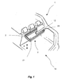
- Fig. 1 and Fig. 2 show schematically a partially cutaway motor vehicle 1 with a loading area 10 and a storage container 2, which is fixed to the underside of a parcel shelf 12.
- the storage container 2 shown is opposite to a fixedly arranged on the motor vehicle 1 carrier 3 between a first position shown in Figure 1, which is hereinafter referred to as stowed position, and a second position shown in Figure 2 for loading and / or unloading. the loading and unloading position, is displaceable.
- the storage container 2 comprises a frame 20 and a support surface 21.
- the support surface 21 is connected to the frame 20 via two side walls 22 visible in FIG.
- the height of the storage container is variable.
- the side walls 22 are deformable for this purpose such that the support surface is movable along the direction A shown by an arrow between a non-use position shown in FIG. 1 and a use position shown in FIG.
- a movement of the support surface 21 in the use position shown in Fig. 2 is carried out automatically in a displacement of the storage container 2 from the stowed position shown in Fig. 1 in the loading and unloading position shown in Fig. 2.
- the bearing surface 21 remains in a non-use position, also in a method of the storage container in the loading and unloading position shown in FIG. 2, first in the non-use position shown in FIG. Only by depositing an object, not shown, the support surface 21 is moved in the use position shown in FIG. 2 in such an embodiment.
- the loaded by an object storage container retains its height shown in Fig. 2 even with a return movement of the storage container relative to the carrier 3 in the storage position shown in Fig. 1.
- the storage container 2 extends substantially over the entire width of an opening of the cargo space 10. In other embodiments, two storage containers are arranged side by side and / or a smaller storage container is provided.
- FIG. 3 schematically shows a module for a storage container comprising a carrier 3 and a frame 20.
- Guide rails 23 are arranged on the frame 20 and cooperate with longitudinal guides 31 arranged on the carrier 3.
- the frame 20 is connected in the illustrated embodiment with the carrier 3 via a push-push connection, so that by slightly pressing the frame 20 in the direction of the carrier 3, the frame 20 against the carrier ver and / or unlocked.
- An extension of the frame 20 in the loading and unloading position for example, supported by a spring force or a similar element.
- any storage compartments can be used.
- storage containers according to the invention comprising one or more deformable sidewall / side walls are used in the module. In the module shown, however, other storage containers are used.
- a storage container according to the invention can be mounted rotatably and / or pivotably in the motor vehicle via storage devices (not shown).
- Such storage facilities are preferably also modular, so that different storage containers can be used on the same storage facilities.
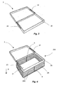
- Fig. 4 shows an embodiment of a storage container 201 according to the invention comprising the frame 20, the support surface 21 and four deformable side walls 24.
- the four side walls 24 are made in one piece from a material web in the illustrated embodiment.
- the side walls 24 are foldable along defined folds 240 according to the concertina or bellows principle.
- two side walls 24 are reinforced by springs 4.
- the springs 4 force the support surface 21 against the direction B shown by the arrow in the direction of the frame 20.
- the side walls 24 are unfolded against the spring force of the springs 4, so that the bearing surface 21 is displaced in the direction of the arrow B and thereby the storage space of the storage container 201 is increased.
- the storage container 201 is locked in a folded non-use position by a suitable member and unlocked by a user when needed.
- the illustrated storage container 201 is displaceable relative to the carrier 3.
- the storage container has a round support surface and is rotatably supported about a substantially vertical axis.
- FIG. 5 shows a further embodiment of a storage container 202 according to the invention, which is displaceably mounted on the carrier 3.
- the storage container 202 comprises the frame 20 and the support surface 21.
- the frame 20 and the support surface 21 are connected by four deformable side walls 25.
- the four side walls 25 are produced in one piece from a material web.
- two side walls 25 are partially cut free to make a linkage 5 visible.
- the connection between the support surface 21 and the frame 20 is reinforced via the linkage 5.
- the support surface 21 is movable along the direction B between a non-use position and a use position.
- By the linkage 5 is the bearing surface 21 preferably in a non-use position and a position of use fixable.
- the linkage 5 is independent of the choice of a side wall.
- a linkage 5, for example, in an embodiment with a foldable according to the accordion principle side wall of FIG. 4 conceivable.
- FIG. 6 shows a further embodiment of a storage container 203 which, in the illustrated embodiment, is likewise displaceably mounted on the carrier 3.
- the frame 20 and the bearing surface 21 are connected to each other via a telescopic side wall 26.
- the storage container 203 with telescoping side wall 26 is shown in FIG. 6 in a user position of the support surface 21 and can be reduced in size by movement of the support surface 21 against the direction B shown.
- the telescopic side wall 26 can be formed in one piece or in several pieces.
- FIG. 7 shows a further embodiment of a storage container 204 displaceably mounted on the carrier 3, wherein the frame 20 is partially cut free.
- winding shafts 60 of two opposite roller blinds 6 are arranged in this embodiment.
- roller blinds 61 are up and unwound. It is also conceivable to arrange the winding shaft 60 on the support surface 21.
- the arrangement shown it is possible to use a common roller blind 61 for the two blinds 6, whose ends are fixed to the two winding shafts 60.
- the support surface 21 has in this embodiment, an edge 210 to prevent falling out of inserted items on the free sides.
- the support surface 21 is moved in the direction B shown by the arrow and thus increases the storage space of the storage container 204.
- the support surface 21 is moved counter to the direction B and the storage container 204 is reduced.
- FIGS. 8 and 9 show variants 204 ', 204 "of the storage container 204 shown in FIG. 7 without an edge of the support surface 21.
- the storage container 204 'shown in FIG. 8 comprises, in addition to the opposite roller blinds 6, a further flexible side wall 7, which can be fastened by a user via hooks 70 to the frame 20 for improving the stability.
- the frame 20 is formed in the illustration as a curved round material on which, for example, the winding shafts 60 are storable.
- the round material can be covered by a corresponding cladding, so that the storage container 204 'can also be inserted into the module shown in FIG. 3.
- FIG. 9 shows a storage container 204 "comprising two roller blinds and a third side wall, which is constructed by pivoting insert plates 8.
- a storage container 204 “comprising two roller blinds and a third side wall, which is constructed by pivoting insert plates 8.
- clips are arranged on the insert plates 8, by means of which the insert plates 8 can be connected to the frame 20.
- the insert plates 8 may protrude beyond the frame 20 as shown, but preferably do not protrude beyond the frame 20 so that the height of the storage container 204 is "independent of the pivoting of the insert plates 8 and the storage container 204" in the module of FIG. 3 can be used.
- roller blinds 61 are made of a material web and thus also form the support surface 21.
- the support surface 21 can be reinforced by means of a shelf, not shown, for example of wood or plastic.
- FIG. 10 shows schematically an exploded view of a detail of the storage container 204 according to FIG. 10, wherein only one of the two roller blinds 6 is visible in Fig. 10.
- the winding shafts 60 of the roller blinds 6 are each formed with a pinion 62 and are synchronized via a belt 63. By a parallel arrangement of the two blinds 6 with the same direction of rotation of the winding shafts 60 a simple synchronization via a belt 63 is directly possible.
- the winding shaft 60 is further formed with a locking segment 64.
- a non-rotatably disposed in an opening 200 of the frame 20 push button 65 engages in the locking segment 64, thus preventing rotation of the winding shaft 60.
- the rotationally fixed connection of the push button 65 is released to the frame 20.
- the winding shaft 60 is rotatable about its axis.
- a return spring not shown, for example, a known winding machine, the roller blind 61 is wound on the winding shaft 60 after releasing the lock.
- the roller blind 61 is unwound from the winding shaft 60.
- the locking segment is designed as a ratchet drive, wherein unwinding of the roller blind 61 due to a weight without unlocking the push button 65 is possible, whereas a winding of the roller blind 61 on the winding shaft 60 is possible only by unlocking.
- FIG. 11 shows a further embodiment of a storage container 205, which is displaceably mounted on the carrier 3.
- the support surface 21 and the frame 20 via four blinds 6, which are arranged on the four side surfaces of the storage container 205, connected to each other.
- the not visible in Fig. 11 Wickeiwellen 60 of the blinds 6 are arranged in the frame 20.
- the roller blinds 61 are connectable to each other at the adjacent ends 610 via a zipper. This provides a closed storage container.
- FIG. 12 and 12 show a perspective view of two adjacent roller blinds 6, and FIG. 13 shows a plan view of the detail view according to FIG. 12.
- the mutually adjacent winding shafts 60 of the roller blinds 6 are synchronized with each other via bevel pinions 62 '.
- the winding shafts 60 are mounted on a holder 600.
- At the ends 610 of the adjacent roller blinds 61 mutually complementary hooks 91 of a zipper are arranged.
- a zipper slider 92 is stationary relative to the frame 20, not shown in FIG. 12, for example, mounted on the holder 600.
- zippers with interlocking grooves are used.
- the tear closure is coated in one embodiment, so that the storage container can be closed watertight by the zipper.
- the roller blind 61 and the support surface 21 are preferably formed in one piece.
- Fig. 14 shows schematically a cutting pattern for such an embodiment.
- the roller blinds 61 in each case adjoin an edge of the support surface 21.
- the free edges 610 of the roller blind 61 are formed with mutually complementary hooks 91.
- the support surface 21 is preferably reinforced in such an embodiment of the storage container 205 shown in FIGS. 11 to 13 by a shelf.
- the frame 20 and the support surface 21 are each rectangular.
- other forms are conceivable.
- the storage container is not displaceable, but pivotally mounted different shapes may be advantageous.
- FIGS. 15 to 18 schematically show a rear of a motor vehicle 1 with a storage container 206 according to a further embodiment of the invention.
- FIGS. 15 and 16 show a schematic side view.
- Fig. 17 and 18 show the rear in a perspective view.
- the storage container 206 is mounted displaceably in the motor vehicle 1 via schematically illustrated guide rails 23, the storage container 206 being displaceable between a storage position shown in FIG. 15 and the loading and / or unloading position shown schematically in FIGS. 16, 17 and 18.
- side walls and a frame are formed integrally with each other, wherein a height of the storage container 206, for example, by a telescopic design of the side walls of FIG. 6 is variable.
- the side wall of the storage container 206 is designed, for example, as a foldable side wall.
- FIG. 17 schematically shows the rear of the motor vehicle 1 according to FIG. 16, the storage container 206 being in the loading and / or unloading position as shown in FIG. 16.
- the storage container 206 has a locking mechanism 9, by means of which the storage container in the stowed position shown in FIG. 15 can be locked against movement into the loading and / or unloading position according to FIGS. 16 to 18.
- FIG. 18 shows the motor vehicle 1 according to FIG. 17, wherein the storage container 206 is partially cut free, so that the locking mechanism 9 is better recognizable.
- the locking mechanism 9 shown comprises a lever 90, which can be brought from the unlocking position shown in FIG. 18, in which the lever 90 does not project beyond an upper edge 260 of the storage container 206, into a locking position by pivoting which the lever projects beyond the upper edge 260.
- the lever 90 when the storage container 206 is in the storage position shown in FIG. 15, engage in its locking position behind corresponding elements of a motor vehicle body 13, so that a displacement of the storage container 206 from the storage position shown in Fig. 15 in the in Fig. 16 to 18 shown loading and / or unloading position is locked.
- the latch mechanism 9 may include a lock wherein rotation of a key inserted into the latch is translated directly into rotation of the lever 90.
- the locking mechanism 9 is designed such that a pressing of the locking mechanism 9, in particular an actuating knob, causes a rotation of the lever 90.
- a lock may also be provided which electronically and / or mechanically prevents actuation of the locking mechanism.
Applications Claiming Priority (1)
| Application Number | Priority Date | Filing Date | Title |
|---|---|---|---|
| DE102006013974A DE102006013974A1 (de) | 2006-03-15 | 2006-03-15 | Staubehältnis für den Einsatz in einem Laderaum |
Publications (2)
| Publication Number | Publication Date |
|---|---|
| EP1834837A1 true EP1834837A1 (fr) | 2007-09-19 |
| EP1834837B1 EP1834837B1 (fr) | 2009-04-29 |
Family
ID=38229422
Family Applications (1)
| Application Number | Title | Priority Date | Filing Date |
|---|---|---|---|
| EP07004745A Not-in-force EP1834837B1 (fr) | 2006-03-15 | 2007-03-08 | Récipient de retenue pour l'utilisation dans un espace de chargement |
Country Status (3)
| Country | Link |
|---|---|
| EP (1) | EP1834837B1 (fr) |
| AT (1) | ATE430063T1 (fr) |
| DE (2) | DE102006013974A1 (fr) |
Cited By (8)
| Publication number | Priority date | Publication date | Assignee | Title |
|---|---|---|---|---|
| FR2920370A1 (fr) * | 2007-08-30 | 2009-03-06 | Peugeot Citroen Automobiles Sa | Tablette pour volet arriere de vehicule. |
| DE102008019397A1 (de) | 2008-04-14 | 2009-10-29 | Bos Gmbh & Co. Kg | Stauvorrichtung für ein Kraftfahrzeug |
| DE102010046635A1 (de) | 2010-09-20 | 2012-03-22 | Bos Gmbh & Co. Kg | Kraftfahrzeug mit einem Fahrgastraum und einem heckseitigen Laderaum |
| DE102011004412A1 (de) | 2010-09-20 | 2012-03-22 | Bos Gmbh & Co. Kg | Staubehältnis für einen Einsatz in einem Fahrzeuginnenraum |
| DE102010050452A1 (de) | 2010-10-26 | 2012-04-26 | Bos Gmbh & Co. Kg | Laderaum für ein Kraftfahrzeug und Staubehältnis |
| WO2016202418A1 (fr) * | 2015-06-19 | 2016-12-22 | Daimler Ag | Élément de rangement pour l'habitacle d'un véhicule et procédé de fabrication dudit élément |
| GB2554906A (en) * | 2016-10-13 | 2018-04-18 | Ford Global Tech Llc | A trunk lid stowage system |
| FR3089918A1 (fr) * | 2018-12-18 | 2020-06-19 | Renault S.A.S. | Agencement d’un dispositif de rangement à l’intérieur d’un coffre de véhicule automobile |
Families Citing this family (9)
| Publication number | Priority date | Publication date | Assignee | Title |
|---|---|---|---|---|
| US7931177B2 (en) | 2007-08-14 | 2011-04-26 | Bos Gmbh & Co. Kg | Storage container for use in a boot |
| DE202007016318U1 (de) | 2007-09-13 | 2008-02-07 | Bos Gmbh & Co. Kg | Vorrichtung zum Verstauen von Gegenständen in einem Kraftfahrzeug |
| DE102007058255B3 (de) * | 2007-11-26 | 2009-07-02 | Bos Gmbh & Co. Kg | Staufach mit Tragrahmen und Aufnahmevorrichtung für einen Tragrahmen |
| KR101163941B1 (ko) | 2010-12-13 | 2012-07-06 | 보스 게엠베하 운트 코. 카게 | 차량의 폴딩 및 확장 가능한 수납 트레이 어셈블리 |
| CN102837632A (zh) * | 2011-06-21 | 2012-12-26 | 永恒力集团 | 具有存放架的地面运输车 |
| DE102012013013A1 (de) | 2012-06-29 | 2014-01-02 | Volkswagen Aktiengesellschaft | Ablagevorrichtung für den Gepäckraum eines Fahrzeugs |
| DE102013212552B4 (de) | 2013-06-28 | 2015-03-05 | Bos Gmbh & Co. Kg | Stauvorrichtung für einen Laderaum eines Kraftfahrzeugs |
| DE202014006906U1 (de) | 2014-08-29 | 2023-09-08 | Waitkus Engineering Gmbh | Variable Stauraumvorrichtung |
| DE102019004773B4 (de) * | 2019-07-08 | 2022-09-08 | Mercedes-Benz Group AG | Kraftfahrzeug mit einer Heckklappe |
Citations (7)
| Publication number | Priority date | Publication date | Assignee | Title |
|---|---|---|---|---|
| FR2743035A1 (fr) * | 1995-12-29 | 1997-07-04 | Renault | Agencement d'un coffre auxiliaire dans un vehicule automobile |
| DE19858194A1 (de) * | 1998-12-17 | 2000-06-29 | Baumeister & Ostler Gmbh Co | Staubehältnis für den Einsatz in einem Laderaum eines Kraftfahrzeuges |
| EP1332919A2 (fr) * | 2002-01-31 | 2003-08-06 | BOS GmbH & Co. KG | Dispositif de maintien pour un espace de chargement de véhicule |
| DE10332983A1 (de) * | 2003-07-21 | 2005-02-10 | Bayerische Motoren Werke Ag | Vorrichtung zum Verstauen von Gegenständen in einem Kofferraum eines Kraftfahrzeugs |
| FR2876641A1 (fr) * | 2004-10-20 | 2006-04-21 | Faurecia Automotive Ind Snc | Ensemble de tablette de coffre pour vehicule automobile et vehicule correspondant. |
| EP1717104A1 (fr) * | 2005-04-28 | 2006-11-02 | Grupo Antolin Ingenieria, S.A. | Plage arrière pour véhicule |
| DE102005051732A1 (de) * | 2005-10-28 | 2007-05-03 | Volkswagen Ag | Staufachanordnung |
-
2006
- 2006-03-15 DE DE102006013974A patent/DE102006013974A1/de not_active Ceased
-
2007
- 2007-03-08 DE DE502007000654T patent/DE502007000654D1/de active Active
- 2007-03-08 EP EP07004745A patent/EP1834837B1/fr not_active Not-in-force
- 2007-03-08 AT AT07004745T patent/ATE430063T1/de active
Patent Citations (7)
| Publication number | Priority date | Publication date | Assignee | Title |
|---|---|---|---|---|
| FR2743035A1 (fr) * | 1995-12-29 | 1997-07-04 | Renault | Agencement d'un coffre auxiliaire dans un vehicule automobile |
| DE19858194A1 (de) * | 1998-12-17 | 2000-06-29 | Baumeister & Ostler Gmbh Co | Staubehältnis für den Einsatz in einem Laderaum eines Kraftfahrzeuges |
| EP1332919A2 (fr) * | 2002-01-31 | 2003-08-06 | BOS GmbH & Co. KG | Dispositif de maintien pour un espace de chargement de véhicule |
| DE10332983A1 (de) * | 2003-07-21 | 2005-02-10 | Bayerische Motoren Werke Ag | Vorrichtung zum Verstauen von Gegenständen in einem Kofferraum eines Kraftfahrzeugs |
| FR2876641A1 (fr) * | 2004-10-20 | 2006-04-21 | Faurecia Automotive Ind Snc | Ensemble de tablette de coffre pour vehicule automobile et vehicule correspondant. |
| EP1717104A1 (fr) * | 2005-04-28 | 2006-11-02 | Grupo Antolin Ingenieria, S.A. | Plage arrière pour véhicule |
| DE102005051732A1 (de) * | 2005-10-28 | 2007-05-03 | Volkswagen Ag | Staufachanordnung |
Cited By (10)
| Publication number | Priority date | Publication date | Assignee | Title |
|---|---|---|---|---|
| FR2920370A1 (fr) * | 2007-08-30 | 2009-03-06 | Peugeot Citroen Automobiles Sa | Tablette pour volet arriere de vehicule. |
| DE102008019397A1 (de) | 2008-04-14 | 2009-10-29 | Bos Gmbh & Co. Kg | Stauvorrichtung für ein Kraftfahrzeug |
| DE102010046635A1 (de) | 2010-09-20 | 2012-03-22 | Bos Gmbh & Co. Kg | Kraftfahrzeug mit einem Fahrgastraum und einem heckseitigen Laderaum |
| DE102011004412A1 (de) | 2010-09-20 | 2012-03-22 | Bos Gmbh & Co. Kg | Staubehältnis für einen Einsatz in einem Fahrzeuginnenraum |
| DE102010046635B4 (de) * | 2010-09-20 | 2014-11-13 | Bos Gmbh & Co. Kg | Kraftfahrzeug mit einem Fahrgastraum und einem heckseitigen Laderaum sowie Staubehältnis hierfür |
| DE102010050452A1 (de) | 2010-10-26 | 2012-04-26 | Bos Gmbh & Co. Kg | Laderaum für ein Kraftfahrzeug und Staubehältnis |
| DE102010050452B4 (de) * | 2010-10-26 | 2012-10-18 | Bos Gmbh & Co. Kg | Laderaum für ein Kraftfahrzeug und Staubehältnis |
| WO2016202418A1 (fr) * | 2015-06-19 | 2016-12-22 | Daimler Ag | Élément de rangement pour l'habitacle d'un véhicule et procédé de fabrication dudit élément |
| GB2554906A (en) * | 2016-10-13 | 2018-04-18 | Ford Global Tech Llc | A trunk lid stowage system |
| FR3089918A1 (fr) * | 2018-12-18 | 2020-06-19 | Renault S.A.S. | Agencement d’un dispositif de rangement à l’intérieur d’un coffre de véhicule automobile |
Also Published As
| Publication number | Publication date |
|---|---|
| ATE430063T1 (de) | 2009-05-15 |
| DE502007000654D1 (de) | 2009-06-10 |
| DE102006013974A1 (de) | 2007-09-20 |
| EP1834837B1 (fr) | 2009-04-29 |
Similar Documents
| Publication | Publication Date | Title |
|---|---|---|
| EP1834837B1 (fr) | Récipient de retenue pour l'utilisation dans un espace de chargement | |
| DE102007058255B3 (de) | Staufach mit Tragrahmen und Aufnahmevorrichtung für einen Tragrahmen | |
| DE102018114547A1 (de) | Ladeabdeckungssystem mit automatischer Zwischenverriegelung | |
| WO1999052740A1 (fr) | Espace de chargement d'automobile et dispositif de segmentation | |
| EP1955935B1 (fr) | Système de coffre de moto | |
| DE102009052692A1 (de) | Zurückfahrbare Sicherheitsabdeckung für ein Schienensystem in einem Kraftfahrzeug | |
| DE60129259T2 (de) | Verriegelungsvorrichtung | |
| DE19837685A1 (de) | Laderaum für ein Kraftfahrzeug und Segmentierungsvorrichtung | |
| DE10041361A1 (de) | Heckklappe für ein Kraftfahrzeug | |
| DE102017105315A1 (de) | Ausklappbare, ausziehbare ablageanordnung für ein kraftfahrzeug | |
| WO2011151788A1 (fr) | Boîte de transport pour animaux ou pour objets, prévue notamment pour encastrement dans des véhicules | |
| DE102019128069A1 (de) | Verkleidungselement, umfassend ein klappbares Ablagevolumen | |
| DE102007005185B3 (de) | Laderaumabdeckung | |
| DE102015003312A1 (de) | Klappenanordnung für ein Kraftfahrzeug | |
| DE102006024641A1 (de) | Schutzeinrichtung für Kraftfahrzeuge | |
| DE10320108B4 (de) | Kraftfahrzeug mit einer Abschottungseinrichtung | |
| DE102012009675A1 (de) | Anordnung einer schwenkbar gelagerten Klappe an einer Instrumententafel oder an einem Innenverkleidungsteil | |
| EP1870286A2 (fr) | Boîte de module verrouillable manuellement | |
| DE19906052A1 (de) | Ablagevorrichtung in einer Schalttafel eines Kraftfahrzeuges | |
| DE10208642A1 (de) | Laderaumabdeckvorrichtung | |
| DE102012013013A1 (de) | Ablagevorrichtung für den Gepäckraum eines Fahrzeugs | |
| DE2441398A1 (de) | Einrichtung zum verriegeln und entriegeln insbesondere eines am fahrzeugaufbau eines kraftfahrzeuges angeordneten fahrzeugsitzes | |
| DE102014003440B3 (de) | Laderaumabdeckung für ein Fahrzeug | |
| DE102020111493B3 (de) | Aufnahmebehältnis eines oder für ein Innenraumeinrichtungsbauteil eines Kraftfahrzeugs, Innenraumeinrichtungsbauteil eines oder für ein Kraftfahrzeug, Kraftfahrzeug | |
| DE102007007252A1 (de) | Schließanordnung für einen kastenförmigen Fahrzeugaufbau |
Legal Events
| Date | Code | Title | Description |
|---|---|---|---|
| PUAI | Public reference made under article 153(3) epc to a published international application that has entered the european phase |
Free format text: ORIGINAL CODE: 0009012 |
|
| AK | Designated contracting states |
Kind code of ref document: A1 Designated state(s): AT BE BG CH CY CZ DE DK EE ES FI FR GB GR HU IE IS IT LI LT LU LV MC MT NL PL PT RO SE SI SK TR |
|
| AX | Request for extension of the european patent |
Extension state: AL BA HR MK YU |
|
| 17P | Request for examination filed |
Effective date: 20071019 |
|
| 17Q | First examination report despatched |
Effective date: 20071116 |
|
| AKX | Designation fees paid |
Designated state(s): AT BE BG CH CY CZ DE DK EE ES FI FR GB GR HU IE IS IT LI LT LU LV MC MT NL PL PT RO SE SI SK TR |
|
| GRAP | Despatch of communication of intention to grant a patent |
Free format text: ORIGINAL CODE: EPIDOSNIGR1 |
|
| GRAS | Grant fee paid |
Free format text: ORIGINAL CODE: EPIDOSNIGR3 |
|
| GRAA | (expected) grant |
Free format text: ORIGINAL CODE: 0009210 |
|
| AK | Designated contracting states |
Kind code of ref document: B1 Designated state(s): AT BE BG CH CY CZ DE DK EE ES FI FR GB GR HU IE IS IT LI LT LU LV MC MT NL PL PT RO SE SI SK TR |
|
| REG | Reference to a national code |
Ref country code: GB Ref legal event code: FG4D Free format text: NOT ENGLISH |
|
| REG | Reference to a national code |
Ref country code: CH Ref legal event code: EP |
|
| REF | Corresponds to: |
Ref document number: 502007000654 Country of ref document: DE Date of ref document: 20090610 Kind code of ref document: P |
|
| REG | Reference to a national code |
Ref country code: IE Ref legal event code: FG4D |
|
| NLV1 | Nl: lapsed or annulled due to failure to fulfill the requirements of art. 29p and 29m of the patents act | ||
| PG25 | Lapsed in a contracting state [announced via postgrant information from national office to epo] |
Ref country code: FI Free format text: LAPSE BECAUSE OF FAILURE TO SUBMIT A TRANSLATION OF THE DESCRIPTION OR TO PAY THE FEE WITHIN THE PRESCRIBED TIME-LIMIT Effective date: 20090429 Ref country code: LT Free format text: LAPSE BECAUSE OF FAILURE TO SUBMIT A TRANSLATION OF THE DESCRIPTION OR TO PAY THE FEE WITHIN THE PRESCRIBED TIME-LIMIT Effective date: 20090429 Ref country code: ES Free format text: LAPSE BECAUSE OF FAILURE TO SUBMIT A TRANSLATION OF THE DESCRIPTION OR TO PAY THE FEE WITHIN THE PRESCRIBED TIME-LIMIT Effective date: 20090809 Ref country code: PT Free format text: LAPSE BECAUSE OF FAILURE TO SUBMIT A TRANSLATION OF THE DESCRIPTION OR TO PAY THE FEE WITHIN THE PRESCRIBED TIME-LIMIT Effective date: 20090829 |
|
| PG25 | Lapsed in a contracting state [announced via postgrant information from national office to epo] |
Ref country code: LV Free format text: LAPSE BECAUSE OF FAILURE TO SUBMIT A TRANSLATION OF THE DESCRIPTION OR TO PAY THE FEE WITHIN THE PRESCRIBED TIME-LIMIT Effective date: 20090429 Ref country code: SI Free format text: LAPSE BECAUSE OF FAILURE TO SUBMIT A TRANSLATION OF THE DESCRIPTION OR TO PAY THE FEE WITHIN THE PRESCRIBED TIME-LIMIT Effective date: 20090429 Ref country code: SE Free format text: LAPSE BECAUSE OF FAILURE TO SUBMIT A TRANSLATION OF THE DESCRIPTION OR TO PAY THE FEE WITHIN THE PRESCRIBED TIME-LIMIT Effective date: 20090729 Ref country code: IS Free format text: LAPSE BECAUSE OF FAILURE TO SUBMIT A TRANSLATION OF THE DESCRIPTION OR TO PAY THE FEE WITHIN THE PRESCRIBED TIME-LIMIT Effective date: 20090829 Ref country code: PL Free format text: LAPSE BECAUSE OF FAILURE TO SUBMIT A TRANSLATION OF THE DESCRIPTION OR TO PAY THE FEE WITHIN THE PRESCRIBED TIME-LIMIT Effective date: 20090429 Ref country code: NL Free format text: LAPSE BECAUSE OF FAILURE TO SUBMIT A TRANSLATION OF THE DESCRIPTION OR TO PAY THE FEE WITHIN THE PRESCRIBED TIME-LIMIT Effective date: 20090429 |
|
| REG | Reference to a national code |
Ref country code: IE Ref legal event code: FD4D |
|
| PG25 | Lapsed in a contracting state [announced via postgrant information from national office to epo] |
Ref country code: IE Free format text: LAPSE BECAUSE OF FAILURE TO SUBMIT A TRANSLATION OF THE DESCRIPTION OR TO PAY THE FEE WITHIN THE PRESCRIBED TIME-LIMIT Effective date: 20090429 Ref country code: EE Free format text: LAPSE BECAUSE OF FAILURE TO SUBMIT A TRANSLATION OF THE DESCRIPTION OR TO PAY THE FEE WITHIN THE PRESCRIBED TIME-LIMIT Effective date: 20090429 Ref country code: DK Free format text: LAPSE BECAUSE OF FAILURE TO SUBMIT A TRANSLATION OF THE DESCRIPTION OR TO PAY THE FEE WITHIN THE PRESCRIBED TIME-LIMIT Effective date: 20090429 Ref country code: CZ Free format text: LAPSE BECAUSE OF FAILURE TO SUBMIT A TRANSLATION OF THE DESCRIPTION OR TO PAY THE FEE WITHIN THE PRESCRIBED TIME-LIMIT Effective date: 20090429 Ref country code: RO Free format text: LAPSE BECAUSE OF FAILURE TO SUBMIT A TRANSLATION OF THE DESCRIPTION OR TO PAY THE FEE WITHIN THE PRESCRIBED TIME-LIMIT Effective date: 20090429 |
|
| PG25 | Lapsed in a contracting state [announced via postgrant information from national office to epo] |
Ref country code: SK Free format text: LAPSE BECAUSE OF FAILURE TO SUBMIT A TRANSLATION OF THE DESCRIPTION OR TO PAY THE FEE WITHIN THE PRESCRIBED TIME-LIMIT Effective date: 20090429 |
|
| PLBE | No opposition filed within time limit |
Free format text: ORIGINAL CODE: 0009261 |
|
| STAA | Information on the status of an ep patent application or granted ep patent |
Free format text: STATUS: NO OPPOSITION FILED WITHIN TIME LIMIT |
|
| PG25 | Lapsed in a contracting state [announced via postgrant information from national office to epo] |
Ref country code: BG Free format text: LAPSE BECAUSE OF FAILURE TO SUBMIT A TRANSLATION OF THE DESCRIPTION OR TO PAY THE FEE WITHIN THE PRESCRIBED TIME-LIMIT Effective date: 20090729 |
|
| 26N | No opposition filed |
Effective date: 20100201 |
|
| BERE | Be: lapsed |
Owner name: BOS G.M.B.H. & CO. KG Effective date: 20100331 |
|
| PG25 | Lapsed in a contracting state [announced via postgrant information from national office to epo] |
Ref country code: MC Free format text: LAPSE BECAUSE OF NON-PAYMENT OF DUE FEES Effective date: 20100331 Ref country code: GR Free format text: LAPSE BECAUSE OF FAILURE TO SUBMIT A TRANSLATION OF THE DESCRIPTION OR TO PAY THE FEE WITHIN THE PRESCRIBED TIME-LIMIT Effective date: 20090730 |
|
| REG | Reference to a national code |
Ref country code: FR Ref legal event code: ST Effective date: 20101130 |
|
| PG25 | Lapsed in a contracting state [announced via postgrant information from national office to epo] |
Ref country code: FR Free format text: LAPSE BECAUSE OF NON-PAYMENT OF DUE FEES Effective date: 20100331 |
|
| PG25 | Lapsed in a contracting state [announced via postgrant information from national office to epo] |
Ref country code: BE Free format text: LAPSE BECAUSE OF NON-PAYMENT OF DUE FEES Effective date: 20100331 |
|
| PG25 | Lapsed in a contracting state [announced via postgrant information from national office to epo] |
Ref country code: IT Free format text: LAPSE BECAUSE OF FAILURE TO SUBMIT A TRANSLATION OF THE DESCRIPTION OR TO PAY THE FEE WITHIN THE PRESCRIBED TIME-LIMIT Effective date: 20090429 |
|
| PG25 | Lapsed in a contracting state [announced via postgrant information from national office to epo] |
Ref country code: MT Free format text: LAPSE BECAUSE OF FAILURE TO SUBMIT A TRANSLATION OF THE DESCRIPTION OR TO PAY THE FEE WITHIN THE PRESCRIBED TIME-LIMIT Effective date: 20090429 |
|
| REG | Reference to a national code |
Ref country code: CH Ref legal event code: PL |
|
| GBPC | Gb: european patent ceased through non-payment of renewal fee |
Effective date: 20110308 |
|
| PG25 | Lapsed in a contracting state [announced via postgrant information from national office to epo] |
Ref country code: CH Free format text: LAPSE BECAUSE OF NON-PAYMENT OF DUE FEES Effective date: 20110331 Ref country code: LI Free format text: LAPSE BECAUSE OF NON-PAYMENT OF DUE FEES Effective date: 20110331 |
|
| PG25 | Lapsed in a contracting state [announced via postgrant information from national office to epo] |
Ref country code: GB Free format text: LAPSE BECAUSE OF NON-PAYMENT OF DUE FEES Effective date: 20110308 |
|
| PG25 | Lapsed in a contracting state [announced via postgrant information from national office to epo] |
Ref country code: CY Free format text: LAPSE BECAUSE OF FAILURE TO SUBMIT A TRANSLATION OF THE DESCRIPTION OR TO PAY THE FEE WITHIN THE PRESCRIBED TIME-LIMIT Effective date: 20090429 |
|
| PG25 | Lapsed in a contracting state [announced via postgrant information from national office to epo] |
Ref country code: HU Free format text: LAPSE BECAUSE OF FAILURE TO SUBMIT A TRANSLATION OF THE DESCRIPTION OR TO PAY THE FEE WITHIN THE PRESCRIBED TIME-LIMIT Effective date: 20091030 Ref country code: LU Free format text: LAPSE BECAUSE OF NON-PAYMENT OF DUE FEES Effective date: 20100308 |
|
| PG25 | Lapsed in a contracting state [announced via postgrant information from national office to epo] |
Ref country code: TR Free format text: LAPSE BECAUSE OF FAILURE TO SUBMIT A TRANSLATION OF THE DESCRIPTION OR TO PAY THE FEE WITHIN THE PRESCRIBED TIME-LIMIT Effective date: 20090429 |
|
| REG | Reference to a national code |
Ref country code: AT Ref legal event code: MM01 Ref document number: 430063 Country of ref document: AT Kind code of ref document: T Effective date: 20120308 |
|
| PG25 | Lapsed in a contracting state [announced via postgrant information from national office to epo] |
Ref country code: AT Free format text: LAPSE BECAUSE OF NON-PAYMENT OF DUE FEES Effective date: 20120308 |
|
| PGFP | Annual fee paid to national office [announced via postgrant information from national office to epo] |
Ref country code: DE Payment date: 20200319 Year of fee payment: 14 |
|
| REG | Reference to a national code |
Ref country code: DE Ref legal event code: R119 Ref document number: 502007000654 Country of ref document: DE |
|
| PG25 | Lapsed in a contracting state [announced via postgrant information from national office to epo] |
Ref country code: DE Free format text: LAPSE BECAUSE OF NON-PAYMENT OF DUE FEES Effective date: 20211001 |