EP1834837A1 - Storage container for use in a storage area - Google Patents
Storage container for use in a storage area Download PDFInfo
- Publication number
- EP1834837A1 EP1834837A1 EP07004745A EP07004745A EP1834837A1 EP 1834837 A1 EP1834837 A1 EP 1834837A1 EP 07004745 A EP07004745 A EP 07004745A EP 07004745 A EP07004745 A EP 07004745A EP 1834837 A1 EP1834837 A1 EP 1834837A1
- Authority
- EP
- European Patent Office
- Prior art keywords
- storage container
- container according
- frame
- support surface
- side wall
- Prior art date
- Legal status (The legal status is an assumption and is not a legal conclusion. Google has not performed a legal analysis and makes no representation as to the accuracy of the status listed.)
- Granted
Links
Images


Classifications
-
- B—PERFORMING OPERATIONS; TRANSPORTING
- B60—VEHICLES IN GENERAL
- B60R—VEHICLES, VEHICLE FITTINGS, OR VEHICLE PARTS, NOT OTHERWISE PROVIDED FOR
- B60R7/00—Stowing or holding appliances inside vehicle primarily intended for personal property smaller than suit-cases, e.g. travelling articles, or maps
- B60R7/02—Stowing or holding appliances inside vehicle primarily intended for personal property smaller than suit-cases, e.g. travelling articles, or maps in separate luggage compartment
-
- B—PERFORMING OPERATIONS; TRANSPORTING
- B60—VEHICLES IN GENERAL
- B60R—VEHICLES, VEHICLE FITTINGS, OR VEHICLE PARTS, NOT OTHERWISE PROVIDED FOR
- B60R5/00—Compartments within vehicle body primarily intended or sufficiently spacious for trunks, suit-cases, or the like
- B60R5/04—Compartments within vehicle body primarily intended or sufficiently spacious for trunks, suit-cases, or the like arranged at rear of vehicle
- B60R5/044—Compartments within vehicle body primarily intended or sufficiently spacious for trunks, suit-cases, or the like arranged at rear of vehicle luggage covering means, e.g. parcel shelves
- B60R5/045—Compartments within vehicle body primarily intended or sufficiently spacious for trunks, suit-cases, or the like arranged at rear of vehicle luggage covering means, e.g. parcel shelves collapsible or transformable
Definitions
- the invention relates to a storage container for use in a loading space of a motor vehicle, which can be fastened on the underside of a parcel shelf and moved for loading into a loading and / or unloading position.
- the invention further relates to a module for mounting a storage container in a motor vehicle.
- Storage containers in which smaller or delicate items in a cargo hold of a motor vehicle are clearly and safely storable, are well known. Especially in larger sedan series a cargo space has a large depth, which is not suitable for all items equally. Storage containers for stowing smaller and / or sensitive items can significantly increase the usefulness of the cargo space here.
- Such storage containers are slidably mounted, for example, on the underside of a parcel shelf in a stowed position and for loading or unloading in a loading or unloading position can be pulled out.
- the storage containers are usually used only temporarily.
- a storage container for use in a loading compartment of a motor vehicle, which can be fastened on the underside of a parcel shelf and moved for loading in a loading and / or unloading position, and a frame, a support surface and at least one, the support surface comprising, connected to the frame, substantially inelastic side wall, wherein the side wall is deformable, so that the height of the storage container is variable.
- the height and thus the size of the storage container can be adjusted by the deformable side wall depending on use. As a result, a minimum amount of the storage container can be realized when not in use, which protrudes only slightly into the hold of the motor vehicle and thus not or only slightly reduces the useful size of the hold when not using the storage container.
- the loading and / or unloading position is preferably selected such that the opening of the storage container at least partially protrudes into an opening of the cargo space, so that a simple loading and / or unloading of the storage container is possible.
- a stowed position is preferably selected such that access to the cargo space by the storage container is not hindered or only slightly impeded, for example, under the parcel shelf.
- the frame and the side wall can be integrally formed.
- the storage container is displaceable in a loading space storable.
- the storage container is, for example, a pull-out drawer.
- the storage takes place for example via arranged on the storage container guide rails, which cooperate with complementary, vehicle-side longitudinal guides.
- the storage container is rotatably or pivotally mounted in the cargo space, for example by means of a substantially vertical axis of rotation.
- the support surface and / or the frame of the storage container are substantially rectangular and connected to each other via at least two, mutually opposite side walls.
- round, oval, triangular, trapezoidal or other bearing surfaces are conceivable.
- the frame preferably has at least two parallel sides, in order to realize a simple displaceability, for example by guide rails and associated longitudinal guides.
- a round frame and a round support surface are provided according to an embodiment.
- the shape of the storage container can be determined depending on a size and / or design of the cargo space.
- the storage container extends over the entire width of an opening of the cargo space. In contrast, in other embodiments, the storage container occupies only a small part of the width of the cargo space.
- the storage container is loaded via a return means, in particular a spring, which forces the support surface in the direction of the frame.
- a return means in particular a spring
- the storage container against a restoring force of the return means is resilient, so that the side surface deformed and the storage container is increased.
- the support surface is forced due to the restoring force in the direction of the frame, so that the storage container occupies a minimum size.
- the storage container is preferably open in its loading and / or unloading position upwards. An object can be inserted into the storage container. Due to the weight of the object, the storage container is enlarged, so that the object does not have the Opening of the cargo space protrudes and the storage container is moved back to its storage position.
- the storage container is generally increased to its maximum size when moved to a loading and / or unloading position and / or due to a load by inserted items.
- the side wall is foldable and / or telescopic.
- the foldable side wall is formed according to an embodiment with a plurality of folds and foldable according to the accordion principle and pulled apart.
- the return means is formed in one embodiment as one or more springs which are incorporated along the side wall, for example, sewn.
- the side wall has no defined folds and is loosely foldable.
- the telescopic side wall is integrally formed of a highly flexible material or Kiscopic.
- the support surface via a linkage with the frame is connected and movable at least between a first non-use position and a second position of use.
- the side wall is formed by a roller blind having at least one winding shaft and a roller blind web which can be wound up and unwound around the winding shaft. It can in one embodiment a return spring of a winding machine of the roller blind act as return means on the support surface.
- the support surface is substantially rectangular and the storage container comprises at least two mutually opposite, synchronized blinds.
- the synchronization is possible, for example, in a co-directional arrangement of the blinds on a simple belt drive.
- the roller blinds of the opposite blinds are integrally formed in one embodiment, wherein also the lying between the side walls bearing surface is shaped by the material of the blind sheets.
- roller blinds are synchronized via bevel pinions.
- roller blinds are arranged on all four sides of a storage container with a rectangular support surface and a rectangular frame, which are synchronized with one another via bevel pinions.
- the storage container comprises two adjoining roller blinds, the roller blinds of which have connecting means complementary to adjacent ends.
- the connecting means are formed in one embodiment as a zipper. Zippers can be formed both with interlocking hook and with corresponding grooves. The zippers can be chosen such that a liquid-tight connection is achieved.
- the connecting means are for example push buttons, Velcro closures or the like.
- the support surface between a first non-use position and a second use position is movable and the adjacent roller blinds are connected by a fixed linking means in a movement in the use position with each other and detachable in a movement in the non-use position.
- the fixed linking means in a zipper, for example, a zipper slider, which is fixedly arranged with respect to the frame. After separation, the roller blinds are each wound around associated winding shafts.
- the roller blind can be locked in at least one position.
- the locking takes place, for example, in one embodiment by a locking segment on the winding shaft, in which a connected to the frame latch can engage, so that rotation of the winding shaft is prevented.
- the winding shaft is rotatable. It can rotate due to a return spring in a direction to wind up the roller blind or, for example, due to a force applied by a user and / or an object force in a direction to unwind the roller blind.
- the locking segment and the latch cooperate as a ratchet drive. In this case, an enlargement of the storage container due to an applied force, i. Unwinding of the roller blind, without unlocking possible, winding the roller blind, i. a reduction of the storage container, however, is only possible by unlocking.
- the side wall and the support surface are integrally formed.
- At least one side wall and / or the support surface can be reinforced by at least one insert plate.
- the side wall and / or the support surface are for example made of fabric.
- the side wall is very flexible and thus well deformable, for example, to a winding shaft rollable or foldable according to the Ziehharminka principle.
- insert plates such as a shelf made of wood or plastic, can be used to reinforce the storage container.
- the insert plate is foldable.
- An insert plate for a side wall for example, arranged adjacent to the support surface and deployed by a user if necessary, so that the storage container is reinforced.
- the insert plate is pivotally mounted on the support surface.
- the insert plate is then, for example, by a user when needed to reinforce the storage container from a position parallel to the support surface in the direction of the side walls pivotable.
- a gift is due to a force, such as a spring force, automatically.
- the storage container can be locked at least in the stowed position against movement into the loading and / or unloading position.
- the locking mechanism comprises in one embodiment a lever which engages under a part of the body and / or in another counter-element for a lock. By pivoting of the lever, the lock is thereby solvable. A pivoting of the lever can be shut off in one embodiment by a lock.
- the frame is mounted via a push-push connection in a carrier and / or on guide rails, in particular displaceably mounted.
- a push-push connection here an opening and / or locking system is called, which is triggered by slight pressing of the frame and / or an actuating element, in particular an actuating knob.
- a lock By lightly pressing a storage container located in the stowed position against a direction into the loading and / or unloading position, a lock can be released.
- locking by pressing on a storage container already in the stowed position can be triggered.
- not the storage container, but only an actuator is pressed.
- a necessary mechanism for this is similar to a ballpoint pen mechanism.
- the unlocked storage container is automatically moved to the loading and / or unloading position.
- a spring is provided for this purpose, which forces the storage container in the loading and / or unloading position.
- a module comprising a carrier in which a frame is movably mounted, wherein in the carrier a storage container can be arranged.
- the frame is preferably mounted in the carrier by means of a push-push connection.
- the frame is slidably mounted in the carrier.
- any storage container can be arranged.
- the module is so in a motor vehicle, for example under a parcel shelf, attachable and the motor vehicle by using an associated storage container to certain equipment and / or model series adaptable.
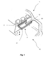
- Fig. 1 and Fig. 2 show schematically a partially cutaway motor vehicle 1 with a loading area 10 and a storage container 2, which is fixed to the underside of a parcel shelf 12.
- the storage container 2 shown is opposite to a fixedly arranged on the motor vehicle 1 carrier 3 between a first position shown in Figure 1, which is hereinafter referred to as stowed position, and a second position shown in Figure 2 for loading and / or unloading. the loading and unloading position, is displaceable.
- the storage container 2 comprises a frame 20 and a support surface 21.
- the support surface 21 is connected to the frame 20 via two side walls 22 visible in FIG.
- the height of the storage container is variable.
- the side walls 22 are deformable for this purpose such that the support surface is movable along the direction A shown by an arrow between a non-use position shown in FIG. 1 and a use position shown in FIG.
- a movement of the support surface 21 in the use position shown in Fig. 2 is carried out automatically in a displacement of the storage container 2 from the stowed position shown in Fig. 1 in the loading and unloading position shown in Fig. 2.
- the bearing surface 21 remains in a non-use position, also in a method of the storage container in the loading and unloading position shown in FIG. 2, first in the non-use position shown in FIG. Only by depositing an object, not shown, the support surface 21 is moved in the use position shown in FIG. 2 in such an embodiment.
- the loaded by an object storage container retains its height shown in Fig. 2 even with a return movement of the storage container relative to the carrier 3 in the storage position shown in Fig. 1.
- the storage container 2 extends substantially over the entire width of an opening of the cargo space 10. In other embodiments, two storage containers are arranged side by side and / or a smaller storage container is provided.
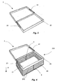
- FIG. 3 schematically shows a module for a storage container comprising a carrier 3 and a frame 20.
- Guide rails 23 are arranged on the frame 20 and cooperate with longitudinal guides 31 arranged on the carrier 3.
- the frame 20 is connected in the illustrated embodiment with the carrier 3 via a push-push connection, so that by slightly pressing the frame 20 in the direction of the carrier 3, the frame 20 against the carrier ver and / or unlocked.
- An extension of the frame 20 in the loading and unloading position for example, supported by a spring force or a similar element.
- any storage compartments can be used.
- storage containers according to the invention comprising one or more deformable sidewall / side walls are used in the module. In the module shown, however, other storage containers are used.
- a storage container according to the invention can be mounted rotatably and / or pivotably in the motor vehicle via storage devices (not shown).
- Such storage facilities are preferably also modular, so that different storage containers can be used on the same storage facilities.
- Fig. 4 shows an embodiment of a storage container 201 according to the invention comprising the frame 20, the support surface 21 and four deformable side walls 24.
- the four side walls 24 are made in one piece from a material web in the illustrated embodiment.
- the side walls 24 are foldable along defined folds 240 according to the concertina or bellows principle.
- two side walls 24 are reinforced by springs 4.
- the springs 4 force the support surface 21 against the direction B shown by the arrow in the direction of the frame 20.
- the side walls 24 are unfolded against the spring force of the springs 4, so that the bearing surface 21 is displaced in the direction of the arrow B and thereby the storage space of the storage container 201 is increased.
- the storage container 201 is locked in a folded non-use position by a suitable member and unlocked by a user when needed.
- the illustrated storage container 201 is displaceable relative to the carrier 3.
- the storage container has a round support surface and is rotatably supported about a substantially vertical axis.
- FIG. 5 shows a further embodiment of a storage container 202 according to the invention, which is displaceably mounted on the carrier 3.
- the storage container 202 comprises the frame 20 and the support surface 21.
- the frame 20 and the support surface 21 are connected by four deformable side walls 25.
- the four side walls 25 are produced in one piece from a material web.
- two side walls 25 are partially cut free to make a linkage 5 visible.
- the connection between the support surface 21 and the frame 20 is reinforced via the linkage 5.
- the support surface 21 is movable along the direction B between a non-use position and a use position.
- By the linkage 5 is the bearing surface 21 preferably in a non-use position and a position of use fixable.
- the linkage 5 is independent of the choice of a side wall.
- a linkage 5, for example, in an embodiment with a foldable according to the accordion principle side wall of FIG. 4 conceivable.
- FIG. 6 shows a further embodiment of a storage container 203 which, in the illustrated embodiment, is likewise displaceably mounted on the carrier 3.
- the frame 20 and the bearing surface 21 are connected to each other via a telescopic side wall 26.
- the storage container 203 with telescoping side wall 26 is shown in FIG. 6 in a user position of the support surface 21 and can be reduced in size by movement of the support surface 21 against the direction B shown.
- the telescopic side wall 26 can be formed in one piece or in several pieces.
- FIG. 7 shows a further embodiment of a storage container 204 displaceably mounted on the carrier 3, wherein the frame 20 is partially cut free.
- winding shafts 60 of two opposite roller blinds 6 are arranged in this embodiment.
- roller blinds 61 are up and unwound. It is also conceivable to arrange the winding shaft 60 on the support surface 21.
- the arrangement shown it is possible to use a common roller blind 61 for the two blinds 6, whose ends are fixed to the two winding shafts 60.
- the support surface 21 has in this embodiment, an edge 210 to prevent falling out of inserted items on the free sides.
- the support surface 21 is moved in the direction B shown by the arrow and thus increases the storage space of the storage container 204.
- the support surface 21 is moved counter to the direction B and the storage container 204 is reduced.
- FIGS. 8 and 9 show variants 204 ', 204 "of the storage container 204 shown in FIG. 7 without an edge of the support surface 21.
- the storage container 204 'shown in FIG. 8 comprises, in addition to the opposite roller blinds 6, a further flexible side wall 7, which can be fastened by a user via hooks 70 to the frame 20 for improving the stability.
- the frame 20 is formed in the illustration as a curved round material on which, for example, the winding shafts 60 are storable.
- the round material can be covered by a corresponding cladding, so that the storage container 204 'can also be inserted into the module shown in FIG. 3.
- FIG. 9 shows a storage container 204 "comprising two roller blinds and a third side wall, which is constructed by pivoting insert plates 8.
- a storage container 204 “comprising two roller blinds and a third side wall, which is constructed by pivoting insert plates 8.
- clips are arranged on the insert plates 8, by means of which the insert plates 8 can be connected to the frame 20.
- the insert plates 8 may protrude beyond the frame 20 as shown, but preferably do not protrude beyond the frame 20 so that the height of the storage container 204 is "independent of the pivoting of the insert plates 8 and the storage container 204" in the module of FIG. 3 can be used.
- roller blinds 61 are made of a material web and thus also form the support surface 21.
- the support surface 21 can be reinforced by means of a shelf, not shown, for example of wood or plastic.
- FIG. 10 shows schematically an exploded view of a detail of the storage container 204 according to FIG. 10, wherein only one of the two roller blinds 6 is visible in Fig. 10.
- the winding shafts 60 of the roller blinds 6 are each formed with a pinion 62 and are synchronized via a belt 63. By a parallel arrangement of the two blinds 6 with the same direction of rotation of the winding shafts 60 a simple synchronization via a belt 63 is directly possible.
- the winding shaft 60 is further formed with a locking segment 64.
- a non-rotatably disposed in an opening 200 of the frame 20 push button 65 engages in the locking segment 64, thus preventing rotation of the winding shaft 60.
- the rotationally fixed connection of the push button 65 is released to the frame 20.
- the winding shaft 60 is rotatable about its axis.
- a return spring not shown, for example, a known winding machine, the roller blind 61 is wound on the winding shaft 60 after releasing the lock.
- the roller blind 61 is unwound from the winding shaft 60.
- the locking segment is designed as a ratchet drive, wherein unwinding of the roller blind 61 due to a weight without unlocking the push button 65 is possible, whereas a winding of the roller blind 61 on the winding shaft 60 is possible only by unlocking.
- FIG. 11 shows a further embodiment of a storage container 205, which is displaceably mounted on the carrier 3.
- the support surface 21 and the frame 20 via four blinds 6, which are arranged on the four side surfaces of the storage container 205, connected to each other.
- the not visible in Fig. 11 Wickeiwellen 60 of the blinds 6 are arranged in the frame 20.
- the roller blinds 61 are connectable to each other at the adjacent ends 610 via a zipper. This provides a closed storage container.
- FIG. 12 and 12 show a perspective view of two adjacent roller blinds 6, and FIG. 13 shows a plan view of the detail view according to FIG. 12.
- the mutually adjacent winding shafts 60 of the roller blinds 6 are synchronized with each other via bevel pinions 62 '.
- the winding shafts 60 are mounted on a holder 600.
- At the ends 610 of the adjacent roller blinds 61 mutually complementary hooks 91 of a zipper are arranged.
- a zipper slider 92 is stationary relative to the frame 20, not shown in FIG. 12, for example, mounted on the holder 600.
- zippers with interlocking grooves are used.
- the tear closure is coated in one embodiment, so that the storage container can be closed watertight by the zipper.
- the roller blind 61 and the support surface 21 are preferably formed in one piece.
- Fig. 14 shows schematically a cutting pattern for such an embodiment.
- the roller blinds 61 in each case adjoin an edge of the support surface 21.
- the free edges 610 of the roller blind 61 are formed with mutually complementary hooks 91.
- the support surface 21 is preferably reinforced in such an embodiment of the storage container 205 shown in FIGS. 11 to 13 by a shelf.
- the frame 20 and the support surface 21 are each rectangular.
- other forms are conceivable.
- the storage container is not displaceable, but pivotally mounted different shapes may be advantageous.
- FIGS. 15 to 18 schematically show a rear of a motor vehicle 1 with a storage container 206 according to a further embodiment of the invention.
- FIGS. 15 and 16 show a schematic side view.
- Fig. 17 and 18 show the rear in a perspective view.
- the storage container 206 is mounted displaceably in the motor vehicle 1 via schematically illustrated guide rails 23, the storage container 206 being displaceable between a storage position shown in FIG. 15 and the loading and / or unloading position shown schematically in FIGS. 16, 17 and 18.
- side walls and a frame are formed integrally with each other, wherein a height of the storage container 206, for example, by a telescopic design of the side walls of FIG. 6 is variable.
- the side wall of the storage container 206 is designed, for example, as a foldable side wall.
- FIG. 17 schematically shows the rear of the motor vehicle 1 according to FIG. 16, the storage container 206 being in the loading and / or unloading position as shown in FIG. 16.
- the storage container 206 has a locking mechanism 9, by means of which the storage container in the stowed position shown in FIG. 15 can be locked against movement into the loading and / or unloading position according to FIGS. 16 to 18.
- FIG. 18 shows the motor vehicle 1 according to FIG. 17, wherein the storage container 206 is partially cut free, so that the locking mechanism 9 is better recognizable.
- the locking mechanism 9 shown comprises a lever 90, which can be brought from the unlocking position shown in FIG. 18, in which the lever 90 does not project beyond an upper edge 260 of the storage container 206, into a locking position by pivoting which the lever projects beyond the upper edge 260.
- the lever 90 when the storage container 206 is in the storage position shown in FIG. 15, engage in its locking position behind corresponding elements of a motor vehicle body 13, so that a displacement of the storage container 206 from the storage position shown in Fig. 15 in the in Fig. 16 to 18 shown loading and / or unloading position is locked.
- the latch mechanism 9 may include a lock wherein rotation of a key inserted into the latch is translated directly into rotation of the lever 90.
- the locking mechanism 9 is designed such that a pressing of the locking mechanism 9, in particular an actuating knob, causes a rotation of the lever 90.
- a lock may also be provided which electronically and / or mechanically prevents actuation of the locking mechanism.
Landscapes
- Engineering & Computer Science (AREA)
- Mechanical Engineering (AREA)
- Vehicle Step Arrangements And Article Storage (AREA)
- Packages (AREA)
Abstract
Description
Die Erfindung betrifft ein Staubehältnis für den Einsatz in einem Laderaum eines Kraftfahrzeugs, das auf der Unterseite einer Hutablage befestigbar und zum Beladen in eine Be- und/oder Entladeposition bewegbar ist. Die Erfindung betrifft weiter ein Modul zur Anbringung eines Staubehältnis in einem Kraftfahrzeug.The invention relates to a storage container for use in a loading space of a motor vehicle, which can be fastened on the underside of a parcel shelf and moved for loading into a loading and / or unloading position. The invention further relates to a module for mounting a storage container in a motor vehicle.
Staubehältnisse, in welchen kleinere oder empfindliche Gegenstände in einem Laderaum eines Kraftfahrzeugs übersichtlich und sicher lagerbar sind, sind allgemein bekannt. Insbesondere in größeren Limousinen-Baureihen hat ein Laderaum eine große Tiefe, welche nicht für alle Gegenstände gleichermaßen geeignet ist. Staubehältnisse zum Verstauen kleinerer und/oder empfindlicher Gegenstände können hier den Nutzwert des Laderaums deutlich erhöhen.Storage containers in which smaller or delicate items in a cargo hold of a motor vehicle are clearly and safely storable, are well known. Especially in larger sedan series a cargo space has a large depth, which is not suitable for all items equally. Storage containers for stowing smaller and / or sensitive items can significantly increase the usefulness of the cargo space here.
Derartige Staubehältnisse sind beispielsweise auf der Unterseite einer Hutablage in einer Verstauposition verschiebbar befestigt und zum Be- oder Entladen in eine Be- oder Entladeposition ausziehbar ist. Die Staubehältnisse werden im Regelfall nur zeitweise genutzt.Such storage containers are slidably mounted, for example, on the underside of a parcel shelf in a stowed position and for loading or unloading in a loading or unloading position can be pulled out. The storage containers are usually used only temporarily.
Es ist Aufgabe der vorliegenden Erfindung, ein zeitweise nutzbares Staubehältnis zu schaffen, durch das Gegenstände sicher verstaubar sind und welches bei Nichtbenutzung einen geringen Platzbedarf hat.It is an object of the present invention to provide a temporarily usable storage container through which objects are securely stowed and which has a small footprint when not in use.
Diese Aufgabe wird gelöst durch ein Staubehältnis für den Einsatz in einem Laderaum eines Kraftfahrzeugs, das auf der Unterseite einer Hutablage befestigbar und zum Beladen in eine Be- und/oder Entladeposition bewegbar ist, und das einen Rahmen, eine Auflagefläche und mindestens eine, die Auflagefläche mit dem Rahmen verbindende, im Wesentlichen unelastische Seitenwand umfasst, wobei die Seitenwand verformbar ist, so dass die Höhe des Staubehältnisses variabel ist.This object is achieved by a storage container for use in a loading compartment of a motor vehicle, which can be fastened on the underside of a parcel shelf and moved for loading in a loading and / or unloading position, and a frame, a support surface and at least one, the support surface comprising, connected to the frame, substantially inelastic side wall, wherein the side wall is deformable, so that the height of the storage container is variable.
Die Höhe und damit die Größe des Staubehältnisses sind durch die verformbare Seitenwand in Abhängigkeit einer Nutzung einstellbar. Dadurch kann bei Nichtbenutzung eine minimale Höhe des Staubehältnisses realisiert werden, wobei dieses nur unwesentlich in den Laderaum des Kraftfahrzeugs hineinragt und somit die Nutzgröße des Laderaums bei Nichtbenutzung des Staubehältnisses nicht oder nur unwesentlich verringert. Die Be- und/oder Entladeposition ist vorzugsweise derart gewählt, dass die Öffnung des Staubehältnisses zumindest teilweise in eine Öffnung des Laderaums hineinragt, so dass ein einfaches Be- und/oder Entladen des Staubehältnisses möglich ist. Eine Verstauposition ist dagegen vorzugsweise derart gewählt, dass ein Zugang zu dem Laderaum durch das Staubehältnis nicht oder nur geringfügig behindert wird, beispielsweise unter der Hutablage. Der Rahmen und die Seitenwand können dabei einstückig ausgebildet sein.The height and thus the size of the storage container can be adjusted by the deformable side wall depending on use. As a result, a minimum amount of the storage container can be realized when not in use, which protrudes only slightly into the hold of the motor vehicle and thus not or only slightly reduces the useful size of the hold when not using the storage container. The loading and / or unloading position is preferably selected such that the opening of the storage container at least partially protrudes into an opening of the cargo space, so that a simple loading and / or unloading of the storage container is possible. On the other hand, a stowed position is preferably selected such that access to the cargo space by the storage container is not hindered or only slightly impeded, for example, under the parcel shelf. The frame and the side wall can be integrally formed.
In einer Weiterführung der Erfindung ist das Staubehältnis verschiebbar in einem Laderaum lagerbar. Das Staubehältnis ist dabei beispielsweise ein ausziehbares Schubfach. Die Lagerung erfolgt beispielsweise über an dem Staubehältnis angeordnete Führungsschienen, welche mit komplementären, fahrzeugseitigen Längsführungen zusammenwirken. In anderen Ausführungsformen ist das Staubehältnis drehbar oder schwenkbar in dem Laderaum gelagert, beispielsweise mittels einer im Wesentlichen vertikalen Drehachse.In a further development of the invention, the storage container is displaceable in a loading space storable. The storage container is, for example, a pull-out drawer. The storage takes place for example via arranged on the storage container guide rails, which cooperate with complementary, vehicle-side longitudinal guides. In In other embodiments, the storage container is rotatably or pivotally mounted in the cargo space, for example by means of a substantially vertical axis of rotation.
In einer Ausführungsform der Erfindung sind die Auflagefläche und/oder der Rahmen des Staubehältnisses im Wesentlichen rechteckig und über mindestens zwei, einander gegenüberliegende Seitenwände miteinander verbunden. In anderen Ausführungsformen sind runde, ovale, dreieckige, trapezförmige oder andere Auflageflächen denkbar. Bei einem verschiebbaren Staubehältnis weist der Rahmen vorzugsweise mindestens zwei parallele Seiten auf, um eine einfache Verschiebbarkeit beispielsweise durch Führungsschienen und zugehörige Längsführungen zu realisieren. Bei einer verschwenkbaren Anordnung sind gemäß einer Ausführungsform ein runder Rahmen und eine runde Auflagefläche vorgesehen. Die Form des Staubehältnisses ist in Abhängigkeit einer Größe und/oder Bauform des Laderaums festlegbar. In einer Ausführungsform reicht das Staubehältnis über die gesamte Breite einer Öffnung des Laderaums. In anderen Ausführungsformen nimmt das Staubehältnis dagegen nur einen geringen Teil Breite des Laderaums ein.In one embodiment of the invention, the support surface and / or the frame of the storage container are substantially rectangular and connected to each other via at least two, mutually opposite side walls. In other embodiments, round, oval, triangular, trapezoidal or other bearing surfaces are conceivable. In a displaceable storage container, the frame preferably has at least two parallel sides, in order to realize a simple displaceability, for example by guide rails and associated longitudinal guides. In a pivotable arrangement, a round frame and a round support surface are provided according to an embodiment. The shape of the storage container can be determined depending on a size and / or design of the cargo space. In one embodiment, the storage container extends over the entire width of an opening of the cargo space. In contrast, in other embodiments, the storage container occupies only a small part of the width of the cargo space.
In einer Weiterbildung der Erfindung ist das Staubehältnis über ein Rückstellmittel, insbesondere eine Feder, belastet, welche die Auflagefläche in Richtung des Rahmens zwingt. Durch ein Eigengewicht eines Gegenstands ist das Staubehältnis entgegen einer Rückstellkraft des Rückstellmittels belastbar, so dass die Seitenfläche verformt und das Staubehältnis vergrößert wird. Ohne eingelegte Gegenstände wird die Auflagefläche dagegen aufgrund der Rückstellkraft in Richtung des Rahmens gezwungen, so dass das Staubehältnis eine minimale Größe einnimmt. Das Staubehältnis ist in seiner Be- und/oder Entladeposition vorzugsweise nach oben offen. Ein Gegenstand ist so in das Staubehältnis einlegbar. Aufgrund des Eigengewichts des Gegenstands wird das Staubehältnis vergrößert, so dass der Gegenstand nicht über die Öffnung des Laderaums hinausragt und das Staubehältnis in seine Verstauposition zurück verschiebbar ist. Reicht das Gewicht des eingelegten Gegenstands für eine Vergrößerung des Staubehältnisses nicht aus, d.h. ragt der Gegenstand noch über das Staubehältnis hinaus, so ist in einer Ausführungsform eine weitere Vergrößerung des Staubehältnisses von Hand durch einen Nutzer möglich. In einer anderen Ausführungsform wird das Staubehältnis bei einem Verschieben in eine Be- und/oder Entladeposition und/oder aufgrund einer Belastung durch eingelegte Gegenstände grundsätzlich auf seine maximale Größe vergrößert.In a further development of the invention, the storage container is loaded via a return means, in particular a spring, which forces the support surface in the direction of the frame. By a dead weight of an object, the storage container against a restoring force of the return means is resilient, so that the side surface deformed and the storage container is increased. Without inserted objects, however, the support surface is forced due to the restoring force in the direction of the frame, so that the storage container occupies a minimum size. The storage container is preferably open in its loading and / or unloading position upwards. An object can be inserted into the storage container. Due to the weight of the object, the storage container is enlarged, so that the object does not have the Opening of the cargo space protrudes and the storage container is moved back to its storage position. If the weight of the inserted object is insufficient for an enlargement of the storage container, ie if the article still projects beyond the storage container, in one embodiment a further enlargement of the storage container by hand by a user is possible. In another embodiment, the storage container is generally increased to its maximum size when moved to a loading and / or unloading position and / or due to a load by inserted items.
In einer Ausführungsform der Erfindung ist die Seitenwand faltbar und/oder teleskopierbar. Die faltbare Seitenwand ist gemäß einer Ausführungsform mit mehreren Falten ausgebildet und nach dem Ziehharmonika-Prinzip faltbar und auseinanderziehbar. Das Rückstellmittel ist dabei in einer Ausführungsform als eine oder mehrere Federn ausgeformt, welche entlang der Seitenwand eingearbeitet, beispielsweise eingenäht, sind. In einer anderen Ausführungsform weist die Seitenwand keine definierten Falten auf und ist lose faltbar. Die teleskopierbare Seitenwand ist einstückig aus einem hochflexiblen Material oder mehrstückig ausbildbar.In one embodiment of the invention, the side wall is foldable and / or telescopic. The foldable side wall is formed according to an embodiment with a plurality of folds and foldable according to the accordion principle and pulled apart. The return means is formed in one embodiment as one or more springs which are incorporated along the side wall, for example, sewn. In another embodiment, the side wall has no defined folds and is loosely foldable. The telescopic side wall is integrally formed of a highly flexible material or mehrstückig.
Gemäß einer Weiterbildung der Erfindung ist die Auflagefläche über ein Gestänge mit dem Rahmen verbindbar und mindestens zwischen einer ersten Nichtbenutzungsstellung und einer zweiten Benutzungsstellung bewegbar. Durch das Gestänge ist ein werkzeugloses Feststellen des Staubehältnisses in mindestens zwei Größen einfach realisierbar.According to one embodiment of the invention, the support surface via a linkage with the frame is connected and movable at least between a first non-use position and a second position of use. By the linkage tool-free detection of the storage container is easily realized in at least two sizes.
In einer anderen Ausführungsform ist die Seitenwand durch ein Rollo mit mindestens einer Wickelwelle und einer um die Wickelwelle auf- und abwickelbaren Rollobahn gebildet. Dabei kann in einer Ausführungsform eine Rückstellfeder eines Wickelautomaten des Rollos als Rückstellmittel auf die Auflagefläche wirken.In another embodiment, the side wall is formed by a roller blind having at least one winding shaft and a roller blind web which can be wound up and unwound around the winding shaft. It can in one embodiment a return spring of a winding machine of the roller blind act as return means on the support surface.
In einer Weiterbildung der Erfindung ist die Auflagefläche im Wesentlichen rechteckig und das Staubehältnis umfasst mindestens zwei, einander gegenüberliegende, synchronisierte Rollos. Die Synchronisation ist beispielsweise bei einer gleichsinnigen Anordnung der Rollos über einen einfachen Riementrieb möglich. Daneben ist es denkbar, die Rollos spiegelsymmetrisch, mit umgekehrtem Drehsinn anzuordnen, wobei für die Synchronisation eine entsprechende Drehrichtungsumkehr erfolgt. Die Rollobahnen der gegenüberliegenden Rollos sind in einer Ausführungsform einstückig ausgebildet, wobei auch die zwischen den Seitenwänden liegende Auflagefläche durch das Material der Rollobahnen gestaltbar ist.In a further development of the invention, the support surface is substantially rectangular and the storage container comprises at least two mutually opposite, synchronized blinds. The synchronization is possible, for example, in a co-directional arrangement of the blinds on a simple belt drive. In addition, it is conceivable to arrange the blinds mirror-symmetrically, with reversed sense of rotation, with a corresponding direction of rotation reversal for the synchronization. The roller blinds of the opposite blinds are integrally formed in one embodiment, wherein also the lying between the side walls bearing surface is shaped by the material of the blind sheets.
In einer weiteren Ausführungsform der Erfindung sind zwei aneinander angrenzende Rollos über Kegelritzel synchronisiert. Gemäß einer Ausführungsform sind an allen vier Seiten eines Staubehältnisses mit einer rechteckigen Auflagefläche und einem rechteckigen Rahmen Rollos angeordnet, welche über Kegelritzel miteinander synchronisiert sind.In a further embodiment of the invention, two adjoining roller blinds are synchronized via bevel pinions. According to one embodiment, roller blinds are arranged on all four sides of a storage container with a rectangular support surface and a rectangular frame, which are synchronized with one another via bevel pinions.
In einer weiteren Ausführungsform umfasst das Staubehältnis zwei aneinander angrenzende Rollos, deren Rollobahnen an angrenzenden Enden komplementäre Verbindungsmittel aufweisen. Durch die Verbindungsmittel sind die Ecken des durch Abwickeln der Rollobahnen vergrößerbaren Staubehältnisses verschließbar. Die Verbindungsmittel sind in einer Ausführungsform als Reißverschluss ausgebildet. Reißverschlüsse können dabei sowohl mit ineinandergreifenden Haken als auch mit entsprechenden Nuten ausgebildet sein. Die Reißverschlüsse können dabei derart gewählt sein, dass eine flüssigkeitsdichte Verbindung erzielt wird. In einer anderen Ausführungsform sind die Verbindungsmittel beispielsweise Druckknöpfe, Klettverschlüsse oder ähnliches. Durch Trennung der Verbindung sind die Rollobahnen jeweils um die zugehörige Wickelwelle zum Verkleinern des Staubehältnisses aufwickelbar.In a further embodiment, the storage container comprises two adjoining roller blinds, the roller blinds of which have connecting means complementary to adjacent ends. By means of the connecting means, the corners of the storage container, which can be enlarged by unwinding the roller blinds, can be closed. The connecting means are formed in one embodiment as a zipper. Zippers can be formed both with interlocking hook and with corresponding grooves. The zippers can be chosen such that a liquid-tight connection is achieved. In another embodiment, the connecting means are for example push buttons, Velcro closures or the like. By Separation of the compound blinds are each wound around the associated winding shaft to reduce the storage container.
In einer Weiterbildung der Erfindung ist die Auflagefläche zwischen einer ersten Nichtbenutzungsstellung und einer zweiten Benutzungsstellung bewegbar und die angrenzenden Rollobahnen sind durch ein feststehendes Verknüpfungsmittel bei einer Bewegung in die Benutzungsstellung miteinander verknüpfbar und bei einer Bewegung in die Nichtbenutzungsstellung voneinander lösbar. Das feststehende Verknüpfungsmittel ist bei einem Reißverschluss beispielsweise ein Reißverschlussschieber, welcher ortsfest bezüglich des Rahmens angeordnet ist. Nach der Trennung sind die Rollobahnen jeweils um zugehörige Wickelwellen aufwickelbar.In a further development of the invention, the support surface between a first non-use position and a second use position is movable and the adjacent roller blinds are connected by a fixed linking means in a movement in the use position with each other and detachable in a movement in the non-use position. The fixed linking means in a zipper, for example, a zipper slider, which is fixedly arranged with respect to the frame. After separation, the roller blinds are each wound around associated winding shafts.
Gemäß einer Weiterbildung der Erfindung ist die Rollobahn in mindestens einer Position verriegelbar. Die Verriegelung erfolgt beispielsweise in einer Ausführungsform durch ein Verriegelungssegment an der Wickelwelle, in welches ein mit dem Rahmen verbundener Riegel eingreifen kann, so dass eine Drehung der Wickelwelle verhindert wird. Durch Lösen des Riegels ist die Wickelwelle drehbar. Sie kann sich dabei aufgrund einer Rückstellfeder in eine Richtung zum Aufwickeln der Rollobahn oder, beispielsweise aufgrund einer durch einen Nutzer und/oder einen Gegenstand aufgebrachten Kraft in eine Richtung zum Abwickeln der Rollobahn drehen. Gemäß einer Ausführungsform wirken das Verriegelungssegment und der Riegel als Ratschenantrieb zusammen. Dabei ist ein Vergrößern des Staubehältnisses aufgrund einer aufgebrachten Kraft, d.h. ein Abwickeln der Rollobahn, ohne Entriegelung möglich, ein Aufwickeln der Rollobahn, d.h. eine Verkleinerung des Staubehältnisses, ist dagegen nur durch Entriegelung möglich.According to one embodiment of the invention, the roller blind can be locked in at least one position. The locking takes place, for example, in one embodiment by a locking segment on the winding shaft, in which a connected to the frame latch can engage, so that rotation of the winding shaft is prevented. By loosening the bolt, the winding shaft is rotatable. It can rotate due to a return spring in a direction to wind up the roller blind or, for example, due to a force applied by a user and / or an object force in a direction to unwind the roller blind. According to one embodiment, the locking segment and the latch cooperate as a ratchet drive. In this case, an enlargement of the storage container due to an applied force, i. Unwinding of the roller blind, without unlocking possible, winding the roller blind, i. a reduction of the storage container, however, is only possible by unlocking.
In einer weiteren Ausführungsform sind die Seitenwand und die Auflagefläche einstückig ausgeformt. Durch die einstückige Ausformung sind optisch ansprechende Lösungen ohne sichtbare Nähte und einfache Fertigungen möglich.In a further embodiment, the side wall and the support surface are integrally formed. By the one-piece shape are visually appealing solutions without visible seams and simple production possible.
In einer weiteren Ausführungsform sind mindestens eine Seitenwand und/oder die Auflagefläche durch mindestens eine Einlegeplatte verstärkbar. Die Seitenwand und/oder die Auflagefläche sind beispielsweise aus Stoff. Die Seitenwand ist dabei sehr flexibel und dadurch gut verformbar, beispielsweise um eine Wickelwelle rollbar oder nach dem Ziehharminka-Prinzip faltbar. Um bei einer hohen Flexibilität der Seitenwand dennoch eine hohe Festigkeit des Staubehältnisses in der Benutzungsstellung zu erhalten, sind Einlegeplatten, beispielsweise ein Einlegeboden aus Holz oder Kunststoff, zur Verstärkung des Staubehältnisses einsetzbar.In a further embodiment, at least one side wall and / or the support surface can be reinforced by at least one insert plate. The side wall and / or the support surface are for example made of fabric. The side wall is very flexible and thus well deformable, for example, to a winding shaft rollable or foldable according to the Ziehharminka principle. In order to still obtain a high strength of the storage container in the use position with a high flexibility of the side wall, insert plates, such as a shelf made of wood or plastic, can be used to reinforce the storage container.
In einer Weiterbildung der Erfindung ist die Einlegeplatte faltbar. Eine Einlegeplatte für eine Seitenwand ist beispielsweise an der Auflagefläche anliegend angeordnet und durch einen Nutzer bei Bedarf entfaltbar, so dass das Staubehältnis verstärkt wird.In an embodiment of the invention, the insert plate is foldable. An insert plate for a side wall, for example, arranged adjacent to the support surface and deployed by a user if necessary, so that the storage container is reinforced.
In einer weiteren Ausführungsform ist die Einlegeplatte schwenkbar an der Auflagefläche angeordnet. Die Einlegeplatte ist dann beispielsweise durch einen Nutzer bei Bedarf zur Verstärkung des Staubehältnisses aus einer Position parallel zur Auflagefläche in Richtung der Seitenwände verschwenkbar. In einer anderen Ausführungsform erfolgt ein Verschenken aufgrund einer Kraft, beispielsweise einer Federkraft, selbsttätig.In a further embodiment, the insert plate is pivotally mounted on the support surface. The insert plate is then, for example, by a user when needed to reinforce the storage container from a position parallel to the support surface in the direction of the side walls pivotable. In another embodiment, a gift is due to a force, such as a spring force, automatically.
In einer weiteren Ausführungsform ist das Staubehältnis mindestens in der Verstauposition gegen ein Bewegen in die Be- und/oder Entladeposition verriegelbar. Der Riegelmechanismus umfasst in einer Ausgestaltung einen Hebel, welcher unter ein Teil der Karosserie und/oder in ein anderes Gegenelement für eine Verriegelung greift. Durch Verschwenken des Hebels ist die Verriegelung dabei lösbar. Ein Verschwenken des Hebels ist in einer Ausgestaltung durch ein Schloss absperrbar.In a further embodiment, the storage container can be locked at least in the stowed position against movement into the loading and / or unloading position. The locking mechanism comprises in one embodiment a lever which engages under a part of the body and / or in another counter-element for a lock. By pivoting of the lever, the lock is thereby solvable. A pivoting of the lever can be shut off in one embodiment by a lock.
In einer weiteren Ausführungsform ist der Rahmen über eine push-push Verbindung in einem Träger und/oder an Führungsschienen gelagert, insbesondere verschiebbar gelagert. Als push-push-Verbindung wird hier ein Öffnungs- und/oder Verriegelungssystem bezeichnet, das durch leichtes Andrücken des Rahmens und/oder eines Betätigungselements, insbesondere eines Betätigungsknopfes, ausgelöst wird. Durch leichtes Andrücken eines in der Verstauposition befindlichen Staubehältnisses entgegen einer Richtung in die Be- und/oder Entladeposition ist eine Verriegelung lösbar. Ebenso ist auch ein Verriegeln durch ein Andrücken eines bereits in der Verstauposition befindlichen Staubehältnisses auslösbar. Alternativ wird nicht das Staubehältnis, sondern lediglich ein Betätigungselement gedrückt. Eine hierfür notwendige Mechanik ähnelt einer Kugelschreibermechanik. Vorzugsweise wird das entriegelte Staubehältnis selbsttätig in die Be- und/oder Entladeposition bewegt. In einer Ausgestaltung ist zu diesem Zweck eine Feder vorgesehen, welche das Staubehältnis in die Be- und/oder Entladeposition zwingt.In a further embodiment, the frame is mounted via a push-push connection in a carrier and / or on guide rails, in particular displaceably mounted. As a push-push connection here an opening and / or locking system is called, which is triggered by slight pressing of the frame and / or an actuating element, in particular an actuating knob. By lightly pressing a storage container located in the stowed position against a direction into the loading and / or unloading position, a lock can be released. Likewise, locking by pressing on a storage container already in the stowed position can be triggered. Alternatively, not the storage container, but only an actuator is pressed. A necessary mechanism for this is similar to a ballpoint pen mechanism. Preferably, the unlocked storage container is automatically moved to the loading and / or unloading position. In one embodiment, a spring is provided for this purpose, which forces the storage container in the loading and / or unloading position.
Die Aufgabe wird weiter gelöst durch ein Modul, umfassend einen Träger, in dem ein Rahmen bewegbar gelagert ist, wobei in den Träger ein Staubehältnis anordenbar ist. Der Rahmen ist vorzugsweise mittels einer push-push-Verbindung in dem Träger gelagert. Gemäß einer Ausführungsform ist der Rahmen verschiebbar in dem Träger gelagert. In dem Rahmen ist ein beliebiges Staubehältnis anordenbar. Das Modul ist so in einem Kraftfahrzeug, beispielsweise unter einer Hutablage, befestigbar und das Kraftfahrzeug durch Einsatz eines zugehörigen Staubehältnisses an bestimme Ausstattungen und/oder Modellreihen anpassbar.The object is further achieved by a module comprising a carrier in which a frame is movably mounted, wherein in the carrier a storage container can be arranged. The frame is preferably mounted in the carrier by means of a push-push connection. According to one embodiment, the frame is slidably mounted in the carrier. In the frame any storage container can be arranged. The module is so in a motor vehicle, for example under a parcel shelf, attachable and the motor vehicle by using an associated storage container to certain equipment and / or model series adaptable.
Weitere Vorteile und Merkmale der Erfindung ergeben sich aus der nachfolgenden Beschreibung von Ausführungsbeispielen der Erfindung, die in den Zeichnungen dargestellt sind. Für gleiche Bauteile werden dabei einheitliche Bezugszeichen verwendet.Further advantages and features of the invention will become apparent from the following description of embodiments of the invention, which are illustrated in the drawings. Uniform reference numbers are used for the same components.
In den Zeichnungen zeigen:
- Fig. 1
- eine schematische Darstellung eines Kraftfahrzeugs mit einem erfindungsgemäßen Staubehältnisses in einer Verstauposition;
- Fig. 2
- eine schematische Darstellung des Kraftfahrzeugs gemäß Fig. 1 mit dem Staubehältnis in einer Be- und Entladeposition;
- Fig. 3
- ein Modul für ein Staubehältnis;
- Fig.4
- eine Ausführungsform eines erfindungsgemäßen Staubehältnisses mit faltbarer Seitenwand;
- Fig. 5
- eine weitere Ausführungsform eines erfindungsgemäßen Staubehältnisses mit faltbarer Seitenwand;
- Fig. 6
- eine Ausführungsform eines erfindungsgemäßen Staubehältnisses mit teleskopierbarer Seitenwand;
- Fig.7
- eine Ausführungsform eines erfindungsgemäßen Staubehältnisses mit zwei gegenüberliegenden Rollos;
- Fig. 8
- eine erste Variante der Ausführungsform gemäß Fig. 7;
- Fig. 9
- eine zweite Variante der Ausführungsform gemäß Fig. 7;
- Fig. 10
- eine Detailansicht der Ausführungsform gemäß Fig. 7;
- Fig. 11
- eine Ausführungsform eines erfindungsgemäßen Staubehältnisses mit vier Rollos;
- Fig. 12
- eine Detailansicht der Ausführungsform gemäß Fig. 11;
- Fig. 13
- eine Draufsicht auf die Detailansicht gemäß Fig. 12;
- Fig. 14
- eine schematische Darstellung einer Stoffbahn zur Verwendung für einen Ausführungsform gemäß Fig. 11.
- Fig. 15
- eine schematische Seitenansicht eines Kraftfahrzeughecks mit einem Staubehältnis in der Verstauposition;
- Fig. 16
- eine schematische Seitenansicht des Kraftfahrzeughecks gemäß Fig. 15, wobei das Staubehältnis sich in der Be- und/oder Entladeposition befindet;
- Fig. 17
- eine perspektivische Darstellung des Kraftfahrzeughecks gemäß Fig. 16;
- Fig. 18
- eine teilweise freigeschnittene, perspektivische Darstellung gemäß Fig. 17;
- Fig. 19
- eine schematische Darstellung eines Verriegelmechanismus für ein Staubehältnis gemäß Fig. 15 in einer Entriegelposition und
- Fig. 20
- eine schematische Darstellung des Verriegelmechanismus gemäß Fig. 20 in einer Verriegelposition.
- Fig. 1
- a schematic representation of a motor vehicle with a storage container according to the invention in a stowed position;
- Fig. 2
- a schematic representation of the motor vehicle of Figure 1 with the storage container in a loading and unloading.
- Fig. 3
- a module for a storage container;
- Figure 4
- an embodiment of a storage container according to the invention with foldable side wall;
- Fig. 5
- a further embodiment of a storage container according to the invention with foldable side wall;
- Fig. 6
- an embodiment of a storage container according to the invention with telescopic side wall;
- Figure 7
- an embodiment of a storage container according to the invention with two opposite blinds;
- Fig. 8
- a first variant of the embodiment of FIG. 7;
- Fig. 9
- a second variant of the embodiment of FIG. 7;
- Fig. 10
- a detailed view of the embodiment of FIG. 7;
- Fig. 11
- an embodiment of a storage container according to the invention with four blinds;
- Fig. 12
- a detailed view of the embodiment of FIG. 11;
- Fig. 13
- a plan view of the detail view of FIG. 12;
- Fig. 14
- a schematic representation of a fabric for use for an embodiment of FIG. 11.
- Fig. 15
- a schematic side view of a vehicle rear with a storage container in the stowed position;
- Fig. 16
- a schematic side view of the motor vehicle rear of Figure 15, wherein the storage container is in the loading and / or unloading;
- Fig. 17
- a perspective view of the motor vehicle rear of FIG. 16;
- Fig. 18
- a partially cutaway perspective view of FIG. 17;
- Fig. 19
- a schematic representation of a locking mechanism for a storage container according to FIG. 15 in a Entriegelposition and
- Fig. 20
- a schematic representation of the locking mechanism of FIG. 20 in a locking position.
Fig. 1 und Fig. 2 zeigen schematisch ein teilweise freigeschnittenes Kraftfahrzeug 1 mit einer Ladefläche 10 und einem Staubehältnis 2, das auf der Unterseite einer Hutablage 12 befestigt ist. Das dargestellte Staubehältnis 2 ist gegenüber einem fest an dem Kraftfahrzeug 1 angeordneten Träger 3 zwischen einer in Fig. 1 dargestellten ersten Position, die im Folgenden als Verstauposition bezeichnet wird, und einer in Fig. 2 dargestellten zweiten Position zum Be- und/oder Entladen, der Be- und Entladeposition, verschiebbar ist. Das Staubehältnis 2 umfasst einen Rahmen 20 und eine Auflagefläche 21. In der dargestellten Ausführungsform ist die Auflagefläche 21 mit dem Rahmen 20 über zwei in Fig. 2 sichtbare Seitenwände 22 verbunden. Wie aus den Fig. 1 und 2 ersichtlich, ist die Höhe des Staubehältnisses variabel. Gemäß der Erfindung sind hierfür die Seitenwände 22 derart verformbar, dass die Auflagefläche entlang der durch einen Pfeil dargestellten Richtung A zwischen einer in Fig. 1 dargestellten Nichtbenutzungsstellung und einer in Fig. 2 dargestellten Benutzungsstellung bewegbar ist.Fig. 1 and Fig. 2 show schematically a partially
Gemäß einer Ausführungsform erfolgt eine Bewegung der Auflagefläche 21 in die in Fig. 2 dargestellte Benutzungsstellung selbsttätig bei einem Verschieben des Staubehältnisses 2 aus der in Fig. 1 dargestellten Verstauposition in die in Fig. 2 dargestellte Be- und Entladeposition. In einer weiteren Ausführungsform bleibt die Auflagefläche 21 auch bei einem Verfahren des Staubehältnisses in die in Fig. 2 dargestellte Be- und Entladeposition zunächst in der in Fig. 1 dargestellten Nichtbenutzungsstellung. Erst durch Ablage eines nicht dargestellten Gegenstandes wird in einer derartigen Ausführungsform die Auflagefläche 21 in die in Fig. 2 dargestellte Benutzungsstellung bewegt. Das durch einen Gegenstand beladene Staubehältnis behält seine in Fig. 2 dargestellte Höhe auch bei einem Rückverschieben des Staubehältnisses relativ zu dem Träger 3 in die in Fig. 1 dargestellte Verstauposition.According to one embodiment, a movement of the
Das Staubehältnis 2 reicht im Wesentlichen über die gesamte Breite einer Öffnung des Laderaums 10. In anderen Ausführungsformen sind zwei Staubehältnisse nebeneinander angeordnet und/oder ein kleineres Staubehältnis vorgesehen.The
Fig. 3 zeigt schematisch ein Modul für ein Staubehältnis umfassend einen Träger 3 und einen Rahmen 20. An dem Rahmen 20 sind Führungsschienen 23 angeordnet, welche mit an dem Träger 3 angeordneten Längsführungen 31 zusammenwirken. Der Rahmen 20 ist in der dargestellten Ausführungsform mit dem Träger 3 über eine push-push Verbindung verbunden, so dass durch leichtes Andrücken des Rahmens 20 in Richtung des Trägers 3 der Rahmen 20 gegenüber dem Träger ver- und/oder entriegelt wird. Ein Ausfahren des Rahmens 20 in die Be- und Entladeposition ist beispielsweise durch eine Federkraft oder ein ähnliches Element unterstützbar. In das in Fig. 3 dargestellten Modul sind beliebige Staufächer einsetzbar. Vorzugsweise werden in das Modul erfindungsgemäße Staubehältnisse, umfassend eine oder mehrere verformbare Seitenwand/Seitenwände eingesetzt. In das dargestellte Modul sind jedoch auch andere Staubehältnisse einsetzbar. Durch das Modul ist so eine gute Anpassbarkeit an verschiedene Ausstattungsvarianten oder Fahrzeugmodelle unter Verwendung teilweise gleicher Bauteile möglich.3 schematically shows a module for a storage container comprising a
In anderen Ausführungsformen ist ein erfindungsgemäßes Staubehältnis über nicht gezeigte Lagereinrichtungen drehbar und/oder schwenkbar in dem Kraftfahrzeug lagerbar. Derartige Lagereinrichtungen sind vorzugsweise ebenfalls modular aufgebaut, so dass unterschiedliche Staubehältnisse an gleich aufgebauten Lagereinrichtungen einsetzbar sind.In other embodiments, a storage container according to the invention can be mounted rotatably and / or pivotably in the motor vehicle via storage devices (not shown). Such storage facilities are preferably also modular, so that different storage containers can be used on the same storage facilities.
Fig. 4 zeigt eine Ausführungsform eines erfindungsgemäßen Staubehältnisses 201 umfassend den Rahmen 20, die Auflagefläche 21 sowie vier verformbare Seitenwände 24. Die vier Seitenwände 24 sind in der dargestellten Ausführungsform aus einer Materialbahn einstückig hergestellt. Die Seitenwände 24 sind entlang definierter Falten 240 nach dem Ziehharmonika- oder Blasebalgprinzip faltbar. In der dargestellten Ausführungsform sind zwei Seitenwände 24 durch Federn 4 verstärkt. Die Federn 4 zwingen die Auflagefläche 21 entgegen der durch den Pfeil dargestellten Richtung B in Richtung des Rahmens 20. Durch das Eigengewicht eines nicht dargestellten Gegenstands, welcher in das Staubehältnis 201 einlegbar ist, werden die Seitenwände 24 entgegen der Federkraft der Federn 4 auseinandergefaltet, so dass die Auflagefläche 21 in Richtung des Pfeils B verschoben wird und dadurch der Stauraum des Staubehältnisses 201 vergrößert wird. In einer anderen Ausführungsform ist das Staubehältnis 201 in einer gefalteten Nichtbenutzungsstellung durch ein geeignetes Element verriegelt und durch einen Nutzer bei Bedarf entriegelbar.Fig. 4 shows an embodiment of a
Das dargestellte Staubehältnis 201 ist gegenüber dem Träger 3 verschiebbar. In anderen Ausführungsformen weist das Staubehältnis eine runde Auflagefläche auf und ist drehbar um eine im Wesentlichen vertikalen Achse gelagert.The illustrated
Fig. 5 zeigt eine weitere Ausführungsform eines erfindungsgemäßen Staubehältnisses 202, welches verschiebbar an dem Träger 3 gelagert ist. Das Staubehältnis 202 umfasst den Rahmen 20 und die Auflagefläche 21. Der Rahmen 20 und die Auflagefläche 21 sind über vier verformbare Seitenwände 25 verbunden. Die vier Seitenwände 25 sind einstückig aus einer Materialbahn herstellbar. In Fig. 5 sind zwei Seitenwände 25 teilweise freigeschnitten, um ein Gestänge 5 sichtbar zu machen. Die Verbindung zwischen der Auflagefläche 21 und dem Rahmen 20 ist über das Gestänge 5 verstärkt. Die Auflagefläche 21 ist entlang der Richtung B zwischen einer Nichtbenutzugsstellung und einer Benutzungsstellung bewegbar. Durch das Gestänge 5 ist die Auflagefläche 21 vorzugsweise in einer Nichtbenutzungsstellung und einer Benutzungsstellung fixierbar. Das Gestänge 5 ist dabei unabhängig von der Wahl einer Seitenwand. So ist ein Gestänge 5 beispielsweise auch bei einer Ausführungsform mit einer nach dem Ziehharmonika-Prinzip faltbaren Seitenwand gemäß Fig. 4 denkbar.FIG. 5 shows a further embodiment of a
Fig. 6 zeigt eine weitere Ausführungsform eines Staubehältnisses 203, welches in der dargestellten Ausführungsform ebenfalls an dem Träger 3 verschiebbar gelagert ist. In der Ausführungsform gemäß Fig. 6 sind der Rahmen 20 und die Auflagefläche 21 über eine teleskopierbare Seitenwand 26 miteinander verbunden. Das Staubehältnis 203 mit teleskopierbarer Seitenwand 26 ist in Fig. 6 in einer Benutzugsstellung der Auflagefläche 21 gezeigt und durch Bewegung der Auflagefläche 21 entgegen der dargestellten Richtung B verkleinerbar. Die teleskopierbare Seitenwand 26 ist einstückig oder mehrstückig ausbildbar.FIG. 6 shows a further embodiment of a
Fig. 7 zeigt eine weitere Ausführungsform eines an dem Träger 3 verschiebbar gelagerten Staubehältnisses 204, wobei der Rahmen 20 teilweise freigeschnitten ist. In dem Rahmen 20 sind bei dieser Ausführungsform Wickelwellen 60 von zwei gegenüberliegende Rollos 6 angeordnet. Auf den Wickelwellen 60 sind jeweils Rollobahnen 61 auf- und abwickelbar. Es ist ebenso denkbar, die Wickelwelle 60 an der Auflagefläche 21 anzuordnen. Durch die dargestellte Anordnung ist es möglich, für die beiden Rollos 6 eine gemeinsame Rollobahn 61 zu verwenden, deren Enden an den beiden Wickelwellen 60 befestigt sind. Die Auflagefläche 21 weist in dieser Ausführungsform einen Rand 210 auf, um ein Herausfallen eingelegter Gegenstände an den freien Seiten zu verhindern. Durch Abwickeln der Rollobahnen 61 von der jeweiligen Wickelwelle 60 wird die Auflagefläche 21 in die durch den Pfeil dargestellte Richtung B bewegt und so der Stauraum des Staubehältnisses 204 vergrößert. Durch Aufwickeln der Rollobahnen 61 auf die Wickelwellen 60 wird die Auflagefläche 21 entgegen der Richtung B bewegt und das Staubehältnis 204 verkleinert.FIG. 7 shows a further embodiment of a
Fig. 8 und 9 zeigen Varianten 204', 204" des in Fig. 7 dargestellten Staubehältnisses 204 ohne einen Rand der Auflagefläche 21.FIGS. 8 and 9
Das in Fig. 8 dargestellte Staubehältnis 204' umfasst neben den sich gegenüberliegenden Rollos 6 eine weitere flexible Seitenwand 7, welche durch einen Nutzer über Haken 70 an dem Rahmen 20 zur Verbesserung der Stabilität befestigbar ist. Der Rahmen 20 ist in der Darstellung als gebogenes Rundmaterial ausgebildet, auf welchem beispielsweise die Wickelwellen 60 lagerbar sind. Das Rundmaterial ist durch eine entsprechende Verkleidung abdeckbar, so dass auch das Staubehältnis 204' in das in Fig. 3 dargestellte Modul einsetzbar ist.The storage container 204 'shown in FIG. 8 comprises, in addition to the
Fig. 9 zeigt ein Staubehältnis 204", umfassend zwei Rollos sowie eine dritte Seitenwand, welche durch ein Verschwenken von Einlegeplatten 8 aufgebaut wird. An den Einlegeplatten 8 sind beispielsweise nicht dargestellte Clipse angeordnet, durch welche die Einlegeplatten 8 mit dem Rahmen 20 verbindbar sind. Die Einlegeplatten 8 können über den Rahmen 20 wie dargestellt hinausragen. Bevorzugt ragen sie jedoch über den Rahmen 20 nicht hinaus, so dass die Höhe des Staubehältnisses 204" unabhängig von dem Verschwenken der Einlegeplatten 8 ist und das Staubehältnis 204" in das Modul gemäß Fig. 3 einsetzbar ist.9 shows a
In den Ausführungsformen gemäß den Fig. 8 und 9 sind die Rollobahnen 61 aus einer Materialbahn hergestellt und bilden so auch die Auflagefläche 21. Durch einen nicht dargestellten Einlegeboden, beispielsweise aus Holz oder Kunststoff, ist die Auflagefläche 21 verstärkbar.In the embodiments according to FIGS. 8 and 9, the
Fig. 10 zeigt schematisch eine Explosionsdarstellung eines Details des Staubehältnisses 204 gemäß Fig. 10, wobei nur eines der zwei Rollos 6 in Fig. 10 sichtbar ist. Die Wickelwellen 60 der Rollos 6 sind jeweils mit einem Ritzel 62 ausgebildet und werden über einen Riemen 63 synchronisiert. Durch eine parallele Anordnung der beiden Rollos 6 mit gleichem Drehsinn der Wickelwellen 60 ist eine einfache Synchronisation über einen Riemen 63 direkt möglich. Die Wickelwelle 60 ist weiter mit einem Verriegelungssegment 64 ausgebildet. Ein drehfest in einer Öffnung 200 des Rahmens 20 angeordneter Druckknopf 65 greift in das Verriegelungssegment 64 und verhindert so eine Drehung der Wickelwelle 60. Durch Betätigung des Druckknopfs 65 durch einen Nutzer wird die drehfeste Verbindung des Druckknopfs 65 mit dem Rahmen 20 gelöst. Dadurch ist die Wickelwelle 60 um ihre Achse drehbar. Durch eine nicht dargestellte Rückstellfeder, beispielsweise einen bekannten Wickelautomaten, wird die Rollobahn 61 nach Lösen der Verriegelung auf die Wickelwelle 60 aufgewickelt. Durch Einlegen eines Gegenstandes in das Staubehältnis 204, dessen Gewichtskraft größer ist als die Kraft der Rückstellfeder, wird die Rollobahn 61 von der Wickelwelle 60 abgewickelt. In einer bevorzugten Ausführungsform ist das Verriegelungssegment als Ratschentrieb ausgebildet, wobei ein Abwickeln der Rollobahn 61 aufgrund einer Gewichtskraft ohne eine Entriegelung über den Druckknopf 65 möglich ist, wohingegen ein Aufwickeln der Rollobahn 61 auf die Wickelwelle 60 nur durch eine Entriegelung möglich ist.10 shows schematically an exploded view of a detail of the
Fig. 11 zeigt eine weitere Ausführungsform eines Staubehältnisses 205, das auf dem Träger 3 verschiebbar gelagert ist. Bei dem Staubehältnis 205 sind die Auflagefläche 21 und der Rahmen 20 über vier Rollos 6, welche an den vier Seitenflächen des Staubehältnisses 205 angeordnet sind, miteinander verbunden. Die in Fig. 11 nicht sichtbaren Wickeiwellen 60 der Rollos 6 sind dabei in dem Rahmen 20 angeordnet. Die Rollobahnen 61 sind an den aneinander angrenzenden Enden 610 über einen Reißverschluss miteinander verbindbar. Dadurch wird ein geschlossenes Staubehältnis bereitgestellt.FIG. 11 shows a further embodiment of a
Fig. 12 und 13 zeigen teilweise freigeschnittene Detailansichten des Staubehältnisses 205 gemäß Fig. 11. Dabei zeigt Fig. 12 eine perspektivische Ansicht zweier angrenzender Rollos 6 und Fig. 13 eine Draufsicht auf die Detailansicht gemäß Fig. 12. Die aneinander angrenzenden Wickelwellen 60 der Rollos 6 sind über Kegelritzel 62' miteinander synchronisiert. Die Wickelwellen 60 sind an einem Halter 600 gelagert. An den Enden 610 der aneinander angrenzenden Rollobahnen 61 sind zueinander komplementäre Haken 91 eines Reißverschlusses angeordnet. Ein Reißverschlussschieber 92 ist ortsfest zu dem in Fig. 12 nicht dargestellten Rahmen 20 beispielsweise an dem Halter 600 gelagert.12 and 12 show a perspective view of two
Durch die ortsfeste Anordnung des Reißverschlussschiebers 92 werden die zueinander komplementären Haken 91 des Reißverschlusses an den Enden 610 der Rollobahn 61 bei einer Bewegung der Auflagefläche 21 entlang der durch einen Pfeil dargestellten Richtung B, d.h. bei einem Abwickeln der Rollobahn 61, miteinander verhakt. Bei einer Bewegung in die entgegengesetzte Richtung werden die Enden 610 der Rollobahn 61 voneinander gelöst und die Rollobahnen 61 sind so jeweils auf die zugehörige Wickelwelle 60 aufwickelbar.The fixed arrangement of the
Anstelle des dargestellten Reißverschlusses mit Haken 91 sind ebenso Reißverschlüsse mit ineinandergreifenden Nuten einsetzbar. Der Reißerschluss ist in einer Ausführungsform beschichtet, so dass das Staubehältnis durch den Reißverschluss wasserdicht verschließbar ist.Instead of the illustrated zipper with
Die Rollobahn 61 und die Auflagefläche 21 sind vorzugsweise einstückig ausgebildet. Fig. 14 zeigt schematisch ein Schnittmuster für eine derartige Ausführungsform. Die Rollobahnen 61 grenzen dabei jeweils an einen Rand der Auflagefläche 21 an. Die freien Ränder 610 der Rollobahn 61 sind mit zueinander komplementären Haken 91 ausgebildet.The
Die Auflagefläche 21 wird bei einer derartigen Ausführungsform des Staubehältnisses 205 gemäß den Fig. 11 bis 13 vorzugsweise durch einen Einlegeboden verstärkt.The
In den dargestellten Ausführungsformen sind der Rahmen 20 und die Auflagefläche 21 jeweils rechteckig. Es sind jedoch auch andere Formen denkbar. Insbesondere bei Ausführungsformen, in welche das Staubehältnis nicht verschiebbar, sondern verschwenkbar gelagert ist können abweichende Formen vorteilhaft sein.In the illustrated embodiments, the
Fig. 15 bis 18 zeigen schematisch ein Heck eines Kraftfahrzeugs 1 mit einem Staubehältnis 206 gemäß einem weiteren Ausführungsbeispiel der Erfindung. Fig. 15 und 16 zeigen eine schematische Seitenansicht.
Fig. 17 und 18 zeigen das Heck in einer perspektivischen Darstellung. Das Staubehältnis 206 ist über schematisch dargestellte Führungsschienen 23 verschieblich in dem Kraftfahrzeug 1 gelagert, wobei das Staubehältnis 206 zwischen einer in Fig. 15 dargestellten Verstauposition und der in Fig. 16, 17 und 18 schematisch dargestellten Be- und/oder Entladeposition verschiebbar ist. Bei dem Staubehältnis 206 sind Seitenwände und ein Rahmen einstückig miteinander ausgeformt, wobei eine Höhe des Staubehältnisses 206 beispielsweise durch eine teleskopierbare Gestaltung der Seitenwände gemäß Fig. 6 veränderbar ist. In anderen Ausgestaltungen ist die Seitenwand des Staubehältnisses 206 beispielsweise als faltbare Seitenwand gestaltet.15 to 18 schematically show a rear of a
Fig. 17 and 18 show the rear in a perspective view. The
Fig. 17 zeigt schematisch das Heck des Kraftfahrzeugs 1 gemäß Fig. 16, wobei das Staubehältnis 206 sich wie in Fig. 16 dargestellt in der Be- und/oder Entladeposition befindet. Das Staubehältnis 206 weist einen Riegelmechanismus 9 auf, durch welchen das Staubehältnis in der in Fig. 15 dargestellten Verstauposition gegen ein Bewegen in die Be- und/oder Entladeposition gemäß Fig. 16 bis 18 verriegelbar ist.17 schematically shows the rear of the
Fig. 18 zeigt das Kraftfahrzeug 1 gemäß Fig. 17, wobei das Staubehältnis 206 teilweise freigeschnitten ist, so dass der Riegelmechanismus 9 besser erkennbar ist. Wie in Fig. 18 dargestellt, umfasst der gezeigte Riegelmechanismus 9 einen Hebel 90, welcher aus der in Fig. 18 dargestellten Entriegelposition, in welcher der Hebel 90 einen obere Rand 260 des Staubehältnisses 206 nicht überragt, durch Verschwenken in eine Verriegelposition bringbar ist, in welcher der Hebel den oberen Rand 260 überragt. Dabei kann der Hebel 90, wenn sich das Staubehältnis 206 in der Verstauposition gemäß Fig. 15 befindet, in seiner Verriegelposition hinter entsprechende Elemente einer Kraftfahrzeugkarosserie 13 greifen, so dass ein Verschieben des Staubehältnisses 206 aus der in Fig. 15 dargestellten Verstauposition in die in den Fig. 16 bis 18 dargestellte Be- und/oder Entladeposition gesperrt ist.FIG. 18 shows the
Die Fig. 19 und 20 zeigen schematisch den Riegelmechanismus 9, wobei sich der Hebel 90 in der Darstellung gemäß Fig. 19 in einer Entriegelposition und in der Darstellung gemäß Fig. 20 in einer zu der Entriegelposition gemäß Fig. 19 um 90° versetzten Verriegelposition befindet. In anderen Ausgestaltungen sind andere Schwenkwinkel denkbar, wobei der Hebel den obere Rand 260 des Staubehältnisses 206 in einer Entriegelposition nicht überragt und in einer Verriegelposition den oberen Rand 260 überragt, so dass er in entsprechende Gegenmittel greifen kann. Der Riegelmechanismus 9 kann ein Schloss umfassen, wobei eine Drehung eines in das Schloss eingeführten Schlüssels direkt in eine Drehung des Hebels 90 umgesetzt wird. In anderen Ausgestaltungen ist der Riegelmechanismus 9 derart gestaltet, dass ein Andrücken des Riegelmechanismus 9, insbesondere eines Betätigungsknopfes, eine Drehung des Hebels 90 bewirkt. Dabei kann ebenfalls ein Schloss vorgesehen sein, welches eine Betätigung des Riegelmechanismus elektronisch und/oder mechanisch verhindert.19 and 20 show schematically the
Claims (19)
dadurch gekennzeichnet, dass
das Staubehältnis (2, 201- 205) einen Rahmen (20), eine Auflagefläche (21) und mindestens eine, die Auflagefläche (21) mit dem Rahmen (20) verbindende, im Wesentlichen unelastische Seitenwand (22, 24, 25, 26, 61) umfasst und
die Seitenwand (22, 24, 25, 26, 61) verformbar ist, so dass die Höhe des Staubehältnisses (2, 201- 205) variabel ist.Storage container for use in a loading space (10) of a motor vehicle (1) which can be fastened on the underside of a parcel shelf (12) and is movable for loading into at least one loading and / or unloading position,
characterized in that
the storage container (2, 201-205) has a frame (20), a support surface (21) and at least one substantially inelastic side wall (22, 24, 25, 26, 30) connecting the support surface (21) to the frame (20). 61) and
the side wall (22, 24, 25, 26, 61) is deformable, so that the height of the storage container (2, 201-205) is variable.
Applications Claiming Priority (1)
| Application Number | Priority Date | Filing Date | Title |
|---|---|---|---|
| DE102006013974A DE102006013974A1 (en) | 2006-03-15 | 2006-03-15 | Storage container for use in a hold |
Publications (2)
| Publication Number | Publication Date |
|---|---|
| EP1834837A1 true EP1834837A1 (en) | 2007-09-19 |
| EP1834837B1 EP1834837B1 (en) | 2009-04-29 |
Family
ID=38229422
Family Applications (1)
| Application Number | Title | Priority Date | Filing Date |
|---|---|---|---|
| EP07004745A Not-in-force EP1834837B1 (en) | 2006-03-15 | 2007-03-08 | Storage container for use in a storage area |
Country Status (3)
| Country | Link |
|---|---|
| EP (1) | EP1834837B1 (en) |
| AT (1) | ATE430063T1 (en) |
| DE (2) | DE102006013974A1 (en) |
Cited By (8)
| Publication number | Priority date | Publication date | Assignee | Title |
|---|---|---|---|---|
| FR2920370A1 (en) * | 2007-08-30 | 2009-03-06 | Peugeot Citroen Automobiles Sa | Rectangular rear shelf for rear shutter of motor vehicle, has adjusting unit adjusting height of walls and arranged in manner to provide variable depth cup shape to shelf, where unit has bars cooperated with locking units fixed on base |
| DE102008019397A1 (en) | 2008-04-14 | 2009-10-29 | Bos Gmbh & Co. Kg | Stowage device for a motor vehicle |
| DE102010046635A1 (en) | 2010-09-20 | 2012-03-22 | Bos Gmbh & Co. Kg | Motor vehicle has passenger compartment and rear loading space, separated by dimensionally stable, horizontal limiting assembly of passenger compartment |
| DE102011004412A1 (en) | 2010-09-20 | 2012-03-22 | Bos Gmbh & Co. Kg | Storage container i.e. transportation container, for arranging rear shelf of closed luggage compartment of e.g. passenger car during shopping, has clamping supports supporting frame and bottom to secure and stabilize side walls |
| DE102010050452A1 (en) | 2010-10-26 | 2012-04-26 | Bos Gmbh & Co. Kg | Luggage compartment for motor vehicle i.e. passenger car, has hinge arrangement attached to fastening unit for connection with limiting surface, and locking unit for fixing frame in loading and unloading position and in storage position |
| WO2016202418A1 (en) * | 2015-06-19 | 2016-12-22 | Daimler Ag | Storage element for the interior of a vehicle and method for the production of said element |
| GB2554906A (en) * | 2016-10-13 | 2018-04-18 | Ford Global Tech Llc | A trunk lid stowage system |
| FR3089918A1 (en) * | 2018-12-18 | 2020-06-19 | Renault S.A.S. | Arrangement of a storage device inside a trunk of a motor vehicle |
Families Citing this family (9)
| Publication number | Priority date | Publication date | Assignee | Title |
|---|---|---|---|---|
| US7931177B2 (en) | 2007-08-14 | 2011-04-26 | Bos Gmbh & Co. Kg | Storage container for use in a boot |
| DE102007045037A1 (en) | 2007-09-13 | 2009-04-02 | Bos Gmbh & Co. Kg | Device for stowing objects in a motor vehicle |
| DE102007058255B3 (en) * | 2007-11-26 | 2009-07-02 | Bos Gmbh & Co. Kg | Storage compartment with supporting frame and receiving device for a supporting frame |
| KR101163941B1 (en) | 2010-12-13 | 2012-07-06 | 보스 게엠베하 운트 코. 카게 | Foldable and expandable storage tray assembly of vehicle |
| CN102837632A (en) * | 2011-06-21 | 2012-12-26 | 永恒力集团 | Ground transport vehicle with storage rack |
| DE102012013013A1 (en) | 2012-06-29 | 2014-01-02 | Volkswagen Aktiengesellschaft | Stacking device for luggage compartment of motor vehicle, has container walls that are pivoted to each other about folding axis between use position and non-use position |
| DE102013212552B4 (en) | 2013-06-28 | 2015-03-05 | Bos Gmbh & Co. Kg | Stowage device for a cargo space of a motor vehicle |
| DE202014006906U1 (en) | 2014-08-29 | 2023-09-08 | Waitkus Engineering Gmbh | Variable storage space device |
| DE102019004773B4 (en) * | 2019-07-08 | 2022-09-08 | Mercedes-Benz Group AG | Motor vehicle with a tailgate |
Citations (7)
| Publication number | Priority date | Publication date | Assignee | Title |
|---|---|---|---|---|
| FR2743035A1 (en) * | 1995-12-29 | 1997-07-04 | Renault | Auxiliary boot for motor vehicle |
| DE19858194A1 (en) * | 1998-12-17 | 2000-06-29 | Baumeister & Ostler Gmbh Co | Collapsible box for use in car boots consists of stable section connected via hinges, with securing parts and locks to fasten it in boot |
| EP1332919A2 (en) * | 2002-01-31 | 2003-08-06 | BOS GmbH & Co. KG | Holding appliance for a loading space of a motor vehicle |
| DE10332983A1 (en) * | 2003-07-21 | 2005-02-10 | Bayerische Motoren Werke Ag | Storage device for automobile luggage compartment using collapsible container received within front upper part of luggage compartment |
| FR2876641A1 (en) * | 2004-10-20 | 2006-04-21 | Faurecia Automotive Ind Snc | Trunk shelf assembly for motor vehicle, has additional shelf movable relative to main shelf between retracted position in which former shelf is besides main shelf and deployed position in which shelves are spaced and define compartment |
| EP1717104A1 (en) * | 2005-04-28 | 2006-11-02 | Grupo Antolin Ingenieria, S.A. | Package tray for vehicles |
| DE102005051732A1 (en) * | 2005-10-28 | 2007-05-03 | Volkswagen Ag | Storage arrangement for taking up load in loading space of vehicle, has receptacle container which can be moved in area below loading space cover whereby receptacle container can be folded |
-
2006
- 2006-03-15 DE DE102006013974A patent/DE102006013974A1/en not_active Ceased
-
2007
- 2007-03-08 AT AT07004745T patent/ATE430063T1/en active
- 2007-03-08 EP EP07004745A patent/EP1834837B1/en not_active Not-in-force
- 2007-03-08 DE DE502007000654T patent/DE502007000654D1/en active Active
Patent Citations (7)
| Publication number | Priority date | Publication date | Assignee | Title |
|---|---|---|---|---|
| FR2743035A1 (en) * | 1995-12-29 | 1997-07-04 | Renault | Auxiliary boot for motor vehicle |
| DE19858194A1 (en) * | 1998-12-17 | 2000-06-29 | Baumeister & Ostler Gmbh Co | Collapsible box for use in car boots consists of stable section connected via hinges, with securing parts and locks to fasten it in boot |
| EP1332919A2 (en) * | 2002-01-31 | 2003-08-06 | BOS GmbH & Co. KG | Holding appliance for a loading space of a motor vehicle |
| DE10332983A1 (en) * | 2003-07-21 | 2005-02-10 | Bayerische Motoren Werke Ag | Storage device for automobile luggage compartment using collapsible container received within front upper part of luggage compartment |
| FR2876641A1 (en) * | 2004-10-20 | 2006-04-21 | Faurecia Automotive Ind Snc | Trunk shelf assembly for motor vehicle, has additional shelf movable relative to main shelf between retracted position in which former shelf is besides main shelf and deployed position in which shelves are spaced and define compartment |
| EP1717104A1 (en) * | 2005-04-28 | 2006-11-02 | Grupo Antolin Ingenieria, S.A. | Package tray for vehicles |
| DE102005051732A1 (en) * | 2005-10-28 | 2007-05-03 | Volkswagen Ag | Storage arrangement for taking up load in loading space of vehicle, has receptacle container which can be moved in area below loading space cover whereby receptacle container can be folded |
Cited By (10)
| Publication number | Priority date | Publication date | Assignee | Title |
|---|---|---|---|---|
| FR2920370A1 (en) * | 2007-08-30 | 2009-03-06 | Peugeot Citroen Automobiles Sa | Rectangular rear shelf for rear shutter of motor vehicle, has adjusting unit adjusting height of walls and arranged in manner to provide variable depth cup shape to shelf, where unit has bars cooperated with locking units fixed on base |
| DE102008019397A1 (en) | 2008-04-14 | 2009-10-29 | Bos Gmbh & Co. Kg | Stowage device for a motor vehicle |
| DE102010046635A1 (en) | 2010-09-20 | 2012-03-22 | Bos Gmbh & Co. Kg | Motor vehicle has passenger compartment and rear loading space, separated by dimensionally stable, horizontal limiting assembly of passenger compartment |
| DE102011004412A1 (en) | 2010-09-20 | 2012-03-22 | Bos Gmbh & Co. Kg | Storage container i.e. transportation container, for arranging rear shelf of closed luggage compartment of e.g. passenger car during shopping, has clamping supports supporting frame and bottom to secure and stabilize side walls |
| DE102010046635B4 (en) * | 2010-09-20 | 2014-11-13 | Bos Gmbh & Co. Kg | Motor vehicle with a passenger compartment and a rear-side cargo space and storage container for this |
| DE102010050452A1 (en) | 2010-10-26 | 2012-04-26 | Bos Gmbh & Co. Kg | Luggage compartment for motor vehicle i.e. passenger car, has hinge arrangement attached to fastening unit for connection with limiting surface, and locking unit for fixing frame in loading and unloading position and in storage position |
| DE102010050452B4 (en) * | 2010-10-26 | 2012-10-18 | Bos Gmbh & Co. Kg | Cargo space for a motor vehicle and storage container |
| WO2016202418A1 (en) * | 2015-06-19 | 2016-12-22 | Daimler Ag | Storage element for the interior of a vehicle and method for the production of said element |
| GB2554906A (en) * | 2016-10-13 | 2018-04-18 | Ford Global Tech Llc | A trunk lid stowage system |
| FR3089918A1 (en) * | 2018-12-18 | 2020-06-19 | Renault S.A.S. | Arrangement of a storage device inside a trunk of a motor vehicle |
Also Published As
| Publication number | Publication date |
|---|---|
| DE102006013974A1 (en) | 2007-09-20 |
| ATE430063T1 (en) | 2009-05-15 |
| DE502007000654D1 (en) | 2009-06-10 |
| EP1834837B1 (en) | 2009-04-29 |
Similar Documents
| Publication | Publication Date | Title |
|---|---|---|
| EP1834837B1 (en) | Storage container for use in a storage area | |
| DE102007058255B3 (en) | Storage compartment with supporting frame and receiving device for a supporting frame | |
| DE102018114547A1 (en) | Loading cover system with automatic interlocking | |
| WO1999052740A1 (en) | Storage facility for a motor vehicle and segmentation device | |
| EP1955935B1 (en) | Motorcycle luggage system | |
| DE102009052692A1 (en) | Retractable safety cover for a rail system in a motor vehicle | |
| DE102014209855A1 (en) | Cargo organizer for vehicles | |
| DE60129259T2 (en) | locking device | |
| DE19837685A1 (en) | Load space for a motor vehicle and segmentation device | |
| DE10041361A1 (en) | Two-part tailgate for vehicle, with upper part pivoted to lower part so that two parts can be folded up against each other in fully open position | |
| DE102017105315A1 (en) | FOLDABLE, EXTENDABLE FASTENER ASSEMBLY FOR A MOTOR VEHICLE | |
| WO2011151788A1 (en) | Transport box for animals or objects, in particular for fitting in vehicles | |
| DE102007005185B3 (en) | Covering device for loading or luggage space of vehicle, particularly passenger car, has system guide moves along curve or contour path having radius of guide profile between a center position and another end position | |
| DE102006024641A1 (en) | Protective device for motor vehicles | |
| DE102019128069A1 (en) | Cladding element, comprising a foldable storage volume | |
| DE10320108B4 (en) | Motor vehicle with a foreclosure device | |
| DE102012009675A1 (en) | Pivoted flap arrangement for instrument panel or for inner lining section of motor vehicles for covering storage tray, particularly glove box, has pivoted flap pivoted through lower pivot axis and is held at inner lining section | |
| EP1870286A2 (en) | Manually lockable module box | |
| DE19906052A1 (en) | Storage compartment in dashboard of motor vehicle is formed as drawer and mounted in dashboard to slide in and out and has locking device for fixing drawer in closed, open or intermediate positions | |
| DE10208642A1 (en) | Boot (trunk) space cover device for estate car (station wagon) has at least one second movable cover element extending from housing in second direction | |
| DE102012013013A1 (en) | Stacking device for luggage compartment of motor vehicle, has container walls that are pivoted to each other about folding axis between use position and non-use position | |
| DE2441398A1 (en) | Securing catch for tipping car seat - with catch hinge in slot mounting for easy release | |
| DE102014003440B3 (en) | Cargo space cover for a vehicle | |
| DE102020111493B3 (en) | Receiving container of or for an interior component of a motor vehicle, interior component of or for a motor vehicle, motor vehicle | |
| DE102007007252A1 (en) | Closure arrangement for box-shaped motor vehicle body, particularly commercial motor vehicle, has cross brace arranged to vertical stake, where two thrust bearings are designed at fitting, that are fitted outside cross brace |
Legal Events
| Date | Code | Title | Description |
|---|---|---|---|
| PUAI | Public reference made under article 153(3) epc to a published international application that has entered the european phase |
Free format text: ORIGINAL CODE: 0009012 |
|
| AK | Designated contracting states |
Kind code of ref document: A1 Designated state(s): AT BE BG CH CY CZ DE DK EE ES FI FR GB GR HU IE IS IT LI LT LU LV MC MT NL PL PT RO SE SI SK TR |
|
| AX | Request for extension of the european patent |
Extension state: AL BA HR MK YU |
|
| 17P | Request for examination filed |
Effective date: 20071019 |
|
| 17Q | First examination report despatched |
Effective date: 20071116 |
|
| AKX | Designation fees paid |
Designated state(s): AT BE BG CH CY CZ DE DK EE ES FI FR GB GR HU IE IS IT LI LT LU LV MC MT NL PL PT RO SE SI SK TR |
|
| GRAP | Despatch of communication of intention to grant a patent |
Free format text: ORIGINAL CODE: EPIDOSNIGR1 |
|
| GRAS | Grant fee paid |
Free format text: ORIGINAL CODE: EPIDOSNIGR3 |
|
| GRAA | (expected) grant |
Free format text: ORIGINAL CODE: 0009210 |
|
| AK | Designated contracting states |
Kind code of ref document: B1 Designated state(s): AT BE BG CH CY CZ DE DK EE ES FI FR GB GR HU IE IS IT LI LT LU LV MC MT NL PL PT RO SE SI SK TR |
|
| REG | Reference to a national code |
Ref country code: GB Ref legal event code: FG4D Free format text: NOT ENGLISH |
|
| REG | Reference to a national code |
Ref country code: CH Ref legal event code: EP |
|
| REF | Corresponds to: |
Ref document number: 502007000654 Country of ref document: DE Date of ref document: 20090610 Kind code of ref document: P |
|
| REG | Reference to a national code |
Ref country code: IE Ref legal event code: FG4D |
|
| NLV1 | Nl: lapsed or annulled due to failure to fulfill the requirements of art. 29p and 29m of the patents act | ||
| PG25 | Lapsed in a contracting state [announced via postgrant information from national office to epo] |
Ref country code: FI Free format text: LAPSE BECAUSE OF FAILURE TO SUBMIT A TRANSLATION OF THE DESCRIPTION OR TO PAY THE FEE WITHIN THE PRESCRIBED TIME-LIMIT Effective date: 20090429 Ref country code: LT Free format text: LAPSE BECAUSE OF FAILURE TO SUBMIT A TRANSLATION OF THE DESCRIPTION OR TO PAY THE FEE WITHIN THE PRESCRIBED TIME-LIMIT Effective date: 20090429 Ref country code: ES Free format text: LAPSE BECAUSE OF FAILURE TO SUBMIT A TRANSLATION OF THE DESCRIPTION OR TO PAY THE FEE WITHIN THE PRESCRIBED TIME-LIMIT Effective date: 20090809 Ref country code: PT Free format text: LAPSE BECAUSE OF FAILURE TO SUBMIT A TRANSLATION OF THE DESCRIPTION OR TO PAY THE FEE WITHIN THE PRESCRIBED TIME-LIMIT Effective date: 20090829 |
|
| PG25 | Lapsed in a contracting state [announced via postgrant information from national office to epo] |
Ref country code: LV Free format text: LAPSE BECAUSE OF FAILURE TO SUBMIT A TRANSLATION OF THE DESCRIPTION OR TO PAY THE FEE WITHIN THE PRESCRIBED TIME-LIMIT Effective date: 20090429 Ref country code: SI Free format text: LAPSE BECAUSE OF FAILURE TO SUBMIT A TRANSLATION OF THE DESCRIPTION OR TO PAY THE FEE WITHIN THE PRESCRIBED TIME-LIMIT Effective date: 20090429 Ref country code: SE Free format text: LAPSE BECAUSE OF FAILURE TO SUBMIT A TRANSLATION OF THE DESCRIPTION OR TO PAY THE FEE WITHIN THE PRESCRIBED TIME-LIMIT Effective date: 20090729 Ref country code: IS Free format text: LAPSE BECAUSE OF FAILURE TO SUBMIT A TRANSLATION OF THE DESCRIPTION OR TO PAY THE FEE WITHIN THE PRESCRIBED TIME-LIMIT Effective date: 20090829 Ref country code: PL Free format text: LAPSE BECAUSE OF FAILURE TO SUBMIT A TRANSLATION OF THE DESCRIPTION OR TO PAY THE FEE WITHIN THE PRESCRIBED TIME-LIMIT Effective date: 20090429 Ref country code: NL Free format text: LAPSE BECAUSE OF FAILURE TO SUBMIT A TRANSLATION OF THE DESCRIPTION OR TO PAY THE FEE WITHIN THE PRESCRIBED TIME-LIMIT Effective date: 20090429 |
|
| REG | Reference to a national code |
Ref country code: IE Ref legal event code: FD4D |
|
| PG25 | Lapsed in a contracting state [announced via postgrant information from national office to epo] |
Ref country code: IE Free format text: LAPSE BECAUSE OF FAILURE TO SUBMIT A TRANSLATION OF THE DESCRIPTION OR TO PAY THE FEE WITHIN THE PRESCRIBED TIME-LIMIT Effective date: 20090429 Ref country code: EE Free format text: LAPSE BECAUSE OF FAILURE TO SUBMIT A TRANSLATION OF THE DESCRIPTION OR TO PAY THE FEE WITHIN THE PRESCRIBED TIME-LIMIT Effective date: 20090429 Ref country code: DK Free format text: LAPSE BECAUSE OF FAILURE TO SUBMIT A TRANSLATION OF THE DESCRIPTION OR TO PAY THE FEE WITHIN THE PRESCRIBED TIME-LIMIT Effective date: 20090429 Ref country code: CZ Free format text: LAPSE BECAUSE OF FAILURE TO SUBMIT A TRANSLATION OF THE DESCRIPTION OR TO PAY THE FEE WITHIN THE PRESCRIBED TIME-LIMIT Effective date: 20090429 Ref country code: RO Free format text: LAPSE BECAUSE OF FAILURE TO SUBMIT A TRANSLATION OF THE DESCRIPTION OR TO PAY THE FEE WITHIN THE PRESCRIBED TIME-LIMIT Effective date: 20090429 |
|
| PG25 | Lapsed in a contracting state [announced via postgrant information from national office to epo] |
Ref country code: SK Free format text: LAPSE BECAUSE OF FAILURE TO SUBMIT A TRANSLATION OF THE DESCRIPTION OR TO PAY THE FEE WITHIN THE PRESCRIBED TIME-LIMIT Effective date: 20090429 |
|
| PLBE | No opposition filed within time limit |
Free format text: ORIGINAL CODE: 0009261 |
|
| STAA | Information on the status of an ep patent application or granted ep patent |
Free format text: STATUS: NO OPPOSITION FILED WITHIN TIME LIMIT |
|
| PG25 | Lapsed in a contracting state [announced via postgrant information from national office to epo] |
Ref country code: BG Free format text: LAPSE BECAUSE OF FAILURE TO SUBMIT A TRANSLATION OF THE DESCRIPTION OR TO PAY THE FEE WITHIN THE PRESCRIBED TIME-LIMIT Effective date: 20090729 |
|
| 26N | No opposition filed |
Effective date: 20100201 |
|
| BERE | Be: lapsed |
Owner name: BOS G.M.B.H. & CO. KG Effective date: 20100331 |
|
| PG25 | Lapsed in a contracting state [announced via postgrant information from national office to epo] |
Ref country code: MC Free format text: LAPSE BECAUSE OF NON-PAYMENT OF DUE FEES Effective date: 20100331 Ref country code: GR Free format text: LAPSE BECAUSE OF FAILURE TO SUBMIT A TRANSLATION OF THE DESCRIPTION OR TO PAY THE FEE WITHIN THE PRESCRIBED TIME-LIMIT Effective date: 20090730 |
|
| REG | Reference to a national code |
Ref country code: FR Ref legal event code: ST Effective date: 20101130 |
|
| PG25 | Lapsed in a contracting state [announced via postgrant information from national office to epo] |
Ref country code: FR Free format text: LAPSE BECAUSE OF NON-PAYMENT OF DUE FEES Effective date: 20100331 |
|
| PG25 | Lapsed in a contracting state [announced via postgrant information from national office to epo] |
Ref country code: BE Free format text: LAPSE BECAUSE OF NON-PAYMENT OF DUE FEES Effective date: 20100331 |
|
| PG25 | Lapsed in a contracting state [announced via postgrant information from national office to epo] |
Ref country code: IT Free format text: LAPSE BECAUSE OF FAILURE TO SUBMIT A TRANSLATION OF THE DESCRIPTION OR TO PAY THE FEE WITHIN THE PRESCRIBED TIME-LIMIT Effective date: 20090429 |
|
| PG25 | Lapsed in a contracting state [announced via postgrant information from national office to epo] |
Ref country code: MT Free format text: LAPSE BECAUSE OF FAILURE TO SUBMIT A TRANSLATION OF THE DESCRIPTION OR TO PAY THE FEE WITHIN THE PRESCRIBED TIME-LIMIT Effective date: 20090429 |
|
| REG | Reference to a national code |
Ref country code: CH Ref legal event code: PL |
|
| GBPC | Gb: european patent ceased through non-payment of renewal fee |
Effective date: 20110308 |
|
| PG25 | Lapsed in a contracting state [announced via postgrant information from national office to epo] |
Ref country code: CH Free format text: LAPSE BECAUSE OF NON-PAYMENT OF DUE FEES Effective date: 20110331 Ref country code: LI Free format text: LAPSE BECAUSE OF NON-PAYMENT OF DUE FEES Effective date: 20110331 |
|
| PG25 | Lapsed in a contracting state [announced via postgrant information from national office to epo] |
Ref country code: GB Free format text: LAPSE BECAUSE OF NON-PAYMENT OF DUE FEES Effective date: 20110308 |
|
| PG25 | Lapsed in a contracting state [announced via postgrant information from national office to epo] |
Ref country code: CY Free format text: LAPSE BECAUSE OF FAILURE TO SUBMIT A TRANSLATION OF THE DESCRIPTION OR TO PAY THE FEE WITHIN THE PRESCRIBED TIME-LIMIT Effective date: 20090429 |
|
| PG25 | Lapsed in a contracting state [announced via postgrant information from national office to epo] |
Ref country code: HU Free format text: LAPSE BECAUSE OF FAILURE TO SUBMIT A TRANSLATION OF THE DESCRIPTION OR TO PAY THE FEE WITHIN THE PRESCRIBED TIME-LIMIT Effective date: 20091030 Ref country code: LU Free format text: LAPSE BECAUSE OF NON-PAYMENT OF DUE FEES Effective date: 20100308 |
|
| PG25 | Lapsed in a contracting state [announced via postgrant information from national office to epo] |
Ref country code: TR Free format text: LAPSE BECAUSE OF FAILURE TO SUBMIT A TRANSLATION OF THE DESCRIPTION OR TO PAY THE FEE WITHIN THE PRESCRIBED TIME-LIMIT Effective date: 20090429 |
|
| REG | Reference to a national code |
Ref country code: AT Ref legal event code: MM01 Ref document number: 430063 Country of ref document: AT Kind code of ref document: T Effective date: 20120308 |
|
| PG25 | Lapsed in a contracting state [announced via postgrant information from national office to epo] |
Ref country code: AT Free format text: LAPSE BECAUSE OF NON-PAYMENT OF DUE FEES Effective date: 20120308 |
|
| PGFP | Annual fee paid to national office [announced via postgrant information from national office to epo] |
Ref country code: DE Payment date: 20200319 Year of fee payment: 14 |
|
| REG | Reference to a national code |
Ref country code: DE Ref legal event code: R119 Ref document number: 502007000654 Country of ref document: DE |
|
| PG25 | Lapsed in a contracting state [announced via postgrant information from national office to epo] |
Ref country code: DE Free format text: LAPSE BECAUSE OF NON-PAYMENT OF DUE FEES Effective date: 20211001 |