EP1829596A1 - Filtre céramique et unité de décontamination de gaz d'échappement - Google Patents
Filtre céramique et unité de décontamination de gaz d'échappement Download PDFInfo
- Publication number
- EP1829596A1 EP1829596A1 EP07003917A EP07003917A EP1829596A1 EP 1829596 A1 EP1829596 A1 EP 1829596A1 EP 07003917 A EP07003917 A EP 07003917A EP 07003917 A EP07003917 A EP 07003917A EP 1829596 A1 EP1829596 A1 EP 1829596A1
- Authority
- EP
- European Patent Office
- Prior art keywords
- filter
- units
- gas flow
- ceramic
- ceramic filter
- Prior art date
- Legal status (The legal status is an assumption and is not a legal conclusion. Google has not performed a legal analysis and makes no representation as to the accuracy of the status listed.)
- Withdrawn
Links
Images


Classifications
-
- B—PERFORMING OPERATIONS; TRANSPORTING
- B01—PHYSICAL OR CHEMICAL PROCESSES OR APPARATUS IN GENERAL
- B01D—SEPARATION
- B01D39/00—Filtering material for liquid or gaseous fluids
- B01D39/14—Other self-supporting filtering material ; Other filtering material
- B01D39/20—Other self-supporting filtering material ; Other filtering material of inorganic material, e.g. asbestos paper, metallic filtering material of non-woven wires
- B01D39/2068—Other inorganic materials, e.g. ceramics
-
- B—PERFORMING OPERATIONS; TRANSPORTING
- B01—PHYSICAL OR CHEMICAL PROCESSES OR APPARATUS IN GENERAL
- B01D—SEPARATION
- B01D46/00—Filters or filtering processes specially modified for separating dispersed particles from gases or vapours
- B01D46/24—Particle separators, e.g. dust precipitators, using rigid hollow filter bodies
- B01D46/2403—Particle separators, e.g. dust precipitators, using rigid hollow filter bodies characterised by the physical shape or structure of the filtering element
- B01D46/2418—Honeycomb filters
- B01D46/2425—Honeycomb filters characterized by parameters related to the physical properties of the honeycomb structure material
- B01D46/2429—Honeycomb filters characterized by parameters related to the physical properties of the honeycomb structure material of the honeycomb walls or cells
-
- B—PERFORMING OPERATIONS; TRANSPORTING
- B01—PHYSICAL OR CHEMICAL PROCESSES OR APPARATUS IN GENERAL
- B01D—SEPARATION
- B01D46/00—Filters or filtering processes specially modified for separating dispersed particles from gases or vapours
- B01D46/0001—Making filtering elements
-
- B—PERFORMING OPERATIONS; TRANSPORTING
- B01—PHYSICAL OR CHEMICAL PROCESSES OR APPARATUS IN GENERAL
- B01D—SEPARATION
- B01D46/00—Filters or filtering processes specially modified for separating dispersed particles from gases or vapours
- B01D46/24—Particle separators, e.g. dust precipitators, using rigid hollow filter bodies
- B01D46/2403—Particle separators, e.g. dust precipitators, using rigid hollow filter bodies characterised by the physical shape or structure of the filtering element
- B01D46/2418—Honeycomb filters
- B01D46/2425—Honeycomb filters characterized by parameters related to the physical properties of the honeycomb structure material
- B01D46/24491—Porosity
-
- B—PERFORMING OPERATIONS; TRANSPORTING
- B01—PHYSICAL OR CHEMICAL PROCESSES OR APPARATUS IN GENERAL
- B01D—SEPARATION
- B01D46/00—Filters or filtering processes specially modified for separating dispersed particles from gases or vapours
- B01D46/24—Particle separators, e.g. dust precipitators, using rigid hollow filter bodies
- B01D46/2403—Particle separators, e.g. dust precipitators, using rigid hollow filter bodies characterised by the physical shape or structure of the filtering element
- B01D46/2418—Honeycomb filters
- B01D46/2425—Honeycomb filters characterized by parameters related to the physical properties of the honeycomb structure material
- B01D46/24492—Pore diameter
-
- B—PERFORMING OPERATIONS; TRANSPORTING
- B01—PHYSICAL OR CHEMICAL PROCESSES OR APPARATUS IN GENERAL
- B01D—SEPARATION
- B01D46/00—Filters or filtering processes specially modified for separating dispersed particles from gases or vapours
- B01D46/24—Particle separators, e.g. dust precipitators, using rigid hollow filter bodies
- B01D46/2403—Particle separators, e.g. dust precipitators, using rigid hollow filter bodies characterised by the physical shape or structure of the filtering element
- B01D46/2418—Honeycomb filters
- B01D46/2451—Honeycomb filters characterized by the geometrical structure, shape, pattern or configuration or parameters related to the geometry of the structure
- B01D46/2455—Honeycomb filters characterized by the geometrical structure, shape, pattern or configuration or parameters related to the geometry of the structure of the whole honeycomb or segments
-
- B—PERFORMING OPERATIONS; TRANSPORTING
- B01—PHYSICAL OR CHEMICAL PROCESSES OR APPARATUS IN GENERAL
- B01D—SEPARATION
- B01D46/00—Filters or filtering processes specially modified for separating dispersed particles from gases or vapours
- B01D46/24—Particle separators, e.g. dust precipitators, using rigid hollow filter bodies
- B01D46/2403—Particle separators, e.g. dust precipitators, using rigid hollow filter bodies characterised by the physical shape or structure of the filtering element
- B01D46/2418—Honeycomb filters
- B01D46/2451—Honeycomb filters characterized by the geometrical structure, shape, pattern or configuration or parameters related to the geometry of the structure
- B01D46/247—Honeycomb filters characterized by the geometrical structure, shape, pattern or configuration or parameters related to the geometry of the structure of the cells
-
- B—PERFORMING OPERATIONS; TRANSPORTING
- B01—PHYSICAL OR CHEMICAL PROCESSES OR APPARATUS IN GENERAL
- B01D—SEPARATION
- B01D46/00—Filters or filtering processes specially modified for separating dispersed particles from gases or vapours
- B01D46/24—Particle separators, e.g. dust precipitators, using rigid hollow filter bodies
- B01D46/2403—Particle separators, e.g. dust precipitators, using rigid hollow filter bodies characterised by the physical shape or structure of the filtering element
- B01D46/2418—Honeycomb filters
- B01D46/2451—Honeycomb filters characterized by the geometrical structure, shape, pattern or configuration or parameters related to the geometry of the structure
- B01D46/2474—Honeycomb filters characterized by the geometrical structure, shape, pattern or configuration or parameters related to the geometry of the structure of the walls along the length of the honeycomb
-
- B—PERFORMING OPERATIONS; TRANSPORTING
- B01—PHYSICAL OR CHEMICAL PROCESSES OR APPARATUS IN GENERAL
- B01D—SEPARATION
- B01D46/00—Filters or filtering processes specially modified for separating dispersed particles from gases or vapours
- B01D46/24—Particle separators, e.g. dust precipitators, using rigid hollow filter bodies
- B01D46/2403—Particle separators, e.g. dust precipitators, using rigid hollow filter bodies characterised by the physical shape or structure of the filtering element
- B01D46/2418—Honeycomb filters
- B01D46/2451—Honeycomb filters characterized by the geometrical structure, shape, pattern or configuration or parameters related to the geometry of the structure
- B01D46/2476—Monolithic structures
-
- B—PERFORMING OPERATIONS; TRANSPORTING
- B01—PHYSICAL OR CHEMICAL PROCESSES OR APPARATUS IN GENERAL
- B01D—SEPARATION
- B01D46/00—Filters or filtering processes specially modified for separating dispersed particles from gases or vapours
- B01D46/24—Particle separators, e.g. dust precipitators, using rigid hollow filter bodies
- B01D46/2403—Particle separators, e.g. dust precipitators, using rigid hollow filter bodies characterised by the physical shape or structure of the filtering element
- B01D46/2418—Honeycomb filters
- B01D46/2451—Honeycomb filters characterized by the geometrical structure, shape, pattern or configuration or parameters related to the geometry of the structure
- B01D46/2478—Structures comprising honeycomb segments
-
- B—PERFORMING OPERATIONS; TRANSPORTING
- B01—PHYSICAL OR CHEMICAL PROCESSES OR APPARATUS IN GENERAL
- B01D—SEPARATION
- B01D46/00—Filters or filtering processes specially modified for separating dispersed particles from gases or vapours
- B01D46/24—Particle separators, e.g. dust precipitators, using rigid hollow filter bodies
- B01D46/2403—Particle separators, e.g. dust precipitators, using rigid hollow filter bodies characterised by the physical shape or structure of the filtering element
- B01D46/2418—Honeycomb filters
- B01D46/2451—Honeycomb filters characterized by the geometrical structure, shape, pattern or configuration or parameters related to the geometry of the structure
- B01D46/2482—Thickness, height, width, length or diameter
-
- B—PERFORMING OPERATIONS; TRANSPORTING
- B01—PHYSICAL OR CHEMICAL PROCESSES OR APPARATUS IN GENERAL
- B01D—SEPARATION
- B01D46/00—Filters or filtering processes specially modified for separating dispersed particles from gases or vapours
- B01D46/24—Particle separators, e.g. dust precipitators, using rigid hollow filter bodies
- B01D46/2403—Particle separators, e.g. dust precipitators, using rigid hollow filter bodies characterised by the physical shape or structure of the filtering element
- B01D46/2418—Honeycomb filters
- B01D46/2451—Honeycomb filters characterized by the geometrical structure, shape, pattern or configuration or parameters related to the geometry of the structure
- B01D46/2484—Cell density, area or aspect ratio
-
- B—PERFORMING OPERATIONS; TRANSPORTING
- B01—PHYSICAL OR CHEMICAL PROCESSES OR APPARATUS IN GENERAL
- B01D—SEPARATION
- B01D46/00—Filters or filtering processes specially modified for separating dispersed particles from gases or vapours
- B01D46/24—Particle separators, e.g. dust precipitators, using rigid hollow filter bodies
- B01D46/2403—Particle separators, e.g. dust precipitators, using rigid hollow filter bodies characterised by the physical shape or structure of the filtering element
- B01D46/2418—Honeycomb filters
- B01D46/2451—Honeycomb filters characterized by the geometrical structure, shape, pattern or configuration or parameters related to the geometry of the structure
- B01D46/2486—Honeycomb filters characterized by the geometrical structure, shape, pattern or configuration or parameters related to the geometry of the structure characterised by the shapes or configurations
- B01D46/249—Quadrangular e.g. square or diamond
-
- B—PERFORMING OPERATIONS; TRANSPORTING
- B01—PHYSICAL OR CHEMICAL PROCESSES OR APPARATUS IN GENERAL
- B01D—SEPARATION
- B01D46/00—Filters or filtering processes specially modified for separating dispersed particles from gases or vapours
- B01D46/42—Auxiliary equipment or operation thereof
- B01D46/4218—Influencing the heat transfer which act passively, e.g. isolations, heat sinks, cooling ribs
-
- B—PERFORMING OPERATIONS; TRANSPORTING
- B01—PHYSICAL OR CHEMICAL PROCESSES OR APPARATUS IN GENERAL
- B01D—SEPARATION
- B01D53/00—Separation of gases or vapours; Recovering vapours of volatile solvents from gases; Chemical or biological purification of waste gases, e.g. engine exhaust gases, smoke, fumes, flue gases, aerosols
- B01D53/34—Chemical or biological purification of waste gases
- B01D53/92—Chemical or biological purification of waste gases of engine exhaust gases
- B01D53/94—Chemical or biological purification of waste gases of engine exhaust gases by catalytic processes
- B01D53/9445—Simultaneously removing carbon monoxide, hydrocarbons or nitrogen oxides making use of three-way catalysts [TWC] or four-way-catalysts [FWC]
- B01D53/9454—Simultaneously removing carbon monoxide, hydrocarbons or nitrogen oxides making use of three-way catalysts [TWC] or four-way-catalysts [FWC] characterised by a specific device
-
- C—CHEMISTRY; METALLURGY
- C04—CEMENTS; CONCRETE; ARTIFICIAL STONE; CERAMICS; REFRACTORIES
- C04B—LIME, MAGNESIA; SLAG; CEMENTS; COMPOSITIONS THEREOF, e.g. MORTARS, CONCRETE OR LIKE BUILDING MATERIALS; ARTIFICIAL STONE; CERAMICS; REFRACTORIES; TREATMENT OF NATURAL STONE
- C04B38/00—Porous mortars, concrete, artificial stone or ceramic ware; Preparation thereof
- C04B38/0006—Honeycomb structures
- C04B38/0016—Honeycomb structures assembled from subunits
-
- F—MECHANICAL ENGINEERING; LIGHTING; HEATING; WEAPONS; BLASTING
- F01—MACHINES OR ENGINES IN GENERAL; ENGINE PLANTS IN GENERAL; STEAM ENGINES
- F01N—GAS-FLOW SILENCERS OR EXHAUST APPARATUS FOR MACHINES OR ENGINES IN GENERAL; GAS-FLOW SILENCERS OR EXHAUST APPARATUS FOR INTERNAL COMBUSTION ENGINES
- F01N13/00—Exhaust or silencing apparatus characterised by constructional features ; Exhaust or silencing apparatus, or parts thereof, having pertinent characteristics not provided for in, or of interest apart from, groups F01N1/00 - F01N5/00, F01N9/00, F01N11/00
- F01N13/009—Exhaust or silencing apparatus characterised by constructional features ; Exhaust or silencing apparatus, or parts thereof, having pertinent characteristics not provided for in, or of interest apart from, groups F01N1/00 - F01N5/00, F01N9/00, F01N11/00 having two or more separate purifying devices arranged in series
- F01N13/0097—Exhaust or silencing apparatus characterised by constructional features ; Exhaust or silencing apparatus, or parts thereof, having pertinent characteristics not provided for in, or of interest apart from, groups F01N1/00 - F01N5/00, F01N9/00, F01N11/00 having two or more separate purifying devices arranged in series the purifying devices are arranged in a single housing
-
- F—MECHANICAL ENGINEERING; LIGHTING; HEATING; WEAPONS; BLASTING
- F01—MACHINES OR ENGINES IN GENERAL; ENGINE PLANTS IN GENERAL; STEAM ENGINES
- F01N—GAS-FLOW SILENCERS OR EXHAUST APPARATUS FOR MACHINES OR ENGINES IN GENERAL; GAS-FLOW SILENCERS OR EXHAUST APPARATUS FOR INTERNAL COMBUSTION ENGINES
- F01N13/00—Exhaust or silencing apparatus characterised by constructional features ; Exhaust or silencing apparatus, or parts thereof, having pertinent characteristics not provided for in, or of interest apart from, groups F01N1/00 - F01N5/00, F01N9/00, F01N11/00
- F01N13/18—Construction facilitating manufacture, assembly, or disassembly
-
- F—MECHANICAL ENGINEERING; LIGHTING; HEATING; WEAPONS; BLASTING
- F01—MACHINES OR ENGINES IN GENERAL; ENGINE PLANTS IN GENERAL; STEAM ENGINES
- F01N—GAS-FLOW SILENCERS OR EXHAUST APPARATUS FOR MACHINES OR ENGINES IN GENERAL; GAS-FLOW SILENCERS OR EXHAUST APPARATUS FOR INTERNAL COMBUSTION ENGINES
- F01N3/00—Exhaust or silencing apparatus having means for purifying, rendering innocuous, or otherwise treating exhaust
- F01N3/02—Exhaust or silencing apparatus having means for purifying, rendering innocuous, or otherwise treating exhaust for cooling, or for removing solid constituents of, exhaust
- F01N3/021—Exhaust or silencing apparatus having means for purifying, rendering innocuous, or otherwise treating exhaust for cooling, or for removing solid constituents of, exhaust by means of filters
- F01N3/022—Exhaust or silencing apparatus having means for purifying, rendering innocuous, or otherwise treating exhaust for cooling, or for removing solid constituents of, exhaust by means of filters characterised by specially adapted filtering structure, e.g. honeycomb, mesh or fibrous
- F01N3/0222—Exhaust or silencing apparatus having means for purifying, rendering innocuous, or otherwise treating exhaust for cooling, or for removing solid constituents of, exhaust by means of filters characterised by specially adapted filtering structure, e.g. honeycomb, mesh or fibrous the structure being monolithic, e.g. honeycombs
-
- F—MECHANICAL ENGINEERING; LIGHTING; HEATING; WEAPONS; BLASTING
- F01—MACHINES OR ENGINES IN GENERAL; ENGINE PLANTS IN GENERAL; STEAM ENGINES
- F01N—GAS-FLOW SILENCERS OR EXHAUST APPARATUS FOR MACHINES OR ENGINES IN GENERAL; GAS-FLOW SILENCERS OR EXHAUST APPARATUS FOR INTERNAL COMBUSTION ENGINES
- F01N3/00—Exhaust or silencing apparatus having means for purifying, rendering innocuous, or otherwise treating exhaust
- F01N3/02—Exhaust or silencing apparatus having means for purifying, rendering innocuous, or otherwise treating exhaust for cooling, or for removing solid constituents of, exhaust
- F01N3/021—Exhaust or silencing apparatus having means for purifying, rendering innocuous, or otherwise treating exhaust for cooling, or for removing solid constituents of, exhaust by means of filters
- F01N3/023—Exhaust or silencing apparatus having means for purifying, rendering innocuous, or otherwise treating exhaust for cooling, or for removing solid constituents of, exhaust by means of filters using means for regenerating the filters, e.g. by burning trapped particles
- F01N3/0231—Exhaust or silencing apparatus having means for purifying, rendering innocuous, or otherwise treating exhaust for cooling, or for removing solid constituents of, exhaust by means of filters using means for regenerating the filters, e.g. by burning trapped particles using special exhaust apparatus upstream of the filter for producing nitrogen dioxide, e.g. for continuous filter regeneration systems [CRT]
-
- F—MECHANICAL ENGINEERING; LIGHTING; HEATING; WEAPONS; BLASTING
- F01—MACHINES OR ENGINES IN GENERAL; ENGINE PLANTS IN GENERAL; STEAM ENGINES
- F01N—GAS-FLOW SILENCERS OR EXHAUST APPARATUS FOR MACHINES OR ENGINES IN GENERAL; GAS-FLOW SILENCERS OR EXHAUST APPARATUS FOR INTERNAL COMBUSTION ENGINES
- F01N3/00—Exhaust or silencing apparatus having means for purifying, rendering innocuous, or otherwise treating exhaust
- F01N3/02—Exhaust or silencing apparatus having means for purifying, rendering innocuous, or otherwise treating exhaust for cooling, or for removing solid constituents of, exhaust
- F01N3/021—Exhaust or silencing apparatus having means for purifying, rendering innocuous, or otherwise treating exhaust for cooling, or for removing solid constituents of, exhaust by means of filters
- F01N3/033—Exhaust or silencing apparatus having means for purifying, rendering innocuous, or otherwise treating exhaust for cooling, or for removing solid constituents of, exhaust by means of filters in combination with other devices
- F01N3/035—Exhaust or silencing apparatus having means for purifying, rendering innocuous, or otherwise treating exhaust for cooling, or for removing solid constituents of, exhaust by means of filters in combination with other devices with catalytic reactors, e.g. catalysed diesel particulate filters
-
- F—MECHANICAL ENGINEERING; LIGHTING; HEATING; WEAPONS; BLASTING
- F01—MACHINES OR ENGINES IN GENERAL; ENGINE PLANTS IN GENERAL; STEAM ENGINES
- F01N—GAS-FLOW SILENCERS OR EXHAUST APPARATUS FOR MACHINES OR ENGINES IN GENERAL; GAS-FLOW SILENCERS OR EXHAUST APPARATUS FOR INTERNAL COMBUSTION ENGINES
- F01N3/00—Exhaust or silencing apparatus having means for purifying, rendering innocuous, or otherwise treating exhaust
- F01N3/08—Exhaust or silencing apparatus having means for purifying, rendering innocuous, or otherwise treating exhaust for rendering innocuous
- F01N3/10—Exhaust or silencing apparatus having means for purifying, rendering innocuous, or otherwise treating exhaust for rendering innocuous by thermal or catalytic conversion of noxious components of exhaust
- F01N3/24—Exhaust or silencing apparatus having means for purifying, rendering innocuous, or otherwise treating exhaust for rendering innocuous by thermal or catalytic conversion of noxious components of exhaust characterised by constructional aspects of converting apparatus
- F01N3/28—Construction of catalytic reactors
- F01N3/2803—Construction of catalytic reactors characterised by structure, by material or by manufacturing of catalyst support
- F01N3/2825—Ceramics
- F01N3/2828—Ceramic multi-channel monoliths, e.g. honeycombs
-
- C—CHEMISTRY; METALLURGY
- C04—CEMENTS; CONCRETE; ARTIFICIAL STONE; CERAMICS; REFRACTORIES
- C04B—LIME, MAGNESIA; SLAG; CEMENTS; COMPOSITIONS THEREOF, e.g. MORTARS, CONCRETE OR LIKE BUILDING MATERIALS; ARTIFICIAL STONE; CERAMICS; REFRACTORIES; TREATMENT OF NATURAL STONE
- C04B2111/00—Mortars, concrete or artificial stone or mixtures to prepare them, characterised by specific function, property or use
- C04B2111/00241—Physical properties of the materials not provided for elsewhere in C04B2111/00
- C04B2111/00413—Materials having an inhomogeneous concentration of ingredients or irregular properties in different layers
-
- C—CHEMISTRY; METALLURGY
- C04—CEMENTS; CONCRETE; ARTIFICIAL STONE; CERAMICS; REFRACTORIES
- C04B—LIME, MAGNESIA; SLAG; CEMENTS; COMPOSITIONS THEREOF, e.g. MORTARS, CONCRETE OR LIKE BUILDING MATERIALS; ARTIFICIAL STONE; CERAMICS; REFRACTORIES; TREATMENT OF NATURAL STONE
- C04B2111/00—Mortars, concrete or artificial stone or mixtures to prepare them, characterised by specific function, property or use
- C04B2111/00474—Uses not provided for elsewhere in C04B2111/00
- C04B2111/00793—Uses not provided for elsewhere in C04B2111/00 as filters or diaphragms
-
- F—MECHANICAL ENGINEERING; LIGHTING; HEATING; WEAPONS; BLASTING
- F01—MACHINES OR ENGINES IN GENERAL; ENGINE PLANTS IN GENERAL; STEAM ENGINES
- F01N—GAS-FLOW SILENCERS OR EXHAUST APPARATUS FOR MACHINES OR ENGINES IN GENERAL; GAS-FLOW SILENCERS OR EXHAUST APPARATUS FOR INTERNAL COMBUSTION ENGINES
- F01N2260/00—Exhaust treating devices having provisions not otherwise provided for
- F01N2260/08—Exhaust treating devices having provisions not otherwise provided for for preventing heat loss or temperature drop, using other means than layers of heat-insulating material
-
- F—MECHANICAL ENGINEERING; LIGHTING; HEATING; WEAPONS; BLASTING
- F01—MACHINES OR ENGINES IN GENERAL; ENGINE PLANTS IN GENERAL; STEAM ENGINES
- F01N—GAS-FLOW SILENCERS OR EXHAUST APPARATUS FOR MACHINES OR ENGINES IN GENERAL; GAS-FLOW SILENCERS OR EXHAUST APPARATUS FOR INTERNAL COMBUSTION ENGINES
- F01N2330/00—Structure of catalyst support or particle filter
- F01N2330/06—Ceramic, e.g. monoliths
-
- F—MECHANICAL ENGINEERING; LIGHTING; HEATING; WEAPONS; BLASTING
- F01—MACHINES OR ENGINES IN GENERAL; ENGINE PLANTS IN GENERAL; STEAM ENGINES
- F01N—GAS-FLOW SILENCERS OR EXHAUST APPARATUS FOR MACHINES OR ENGINES IN GENERAL; GAS-FLOW SILENCERS OR EXHAUST APPARATUS FOR INTERNAL COMBUSTION ENGINES
- F01N2330/00—Structure of catalyst support or particle filter
- F01N2330/30—Honeycomb supports characterised by their structural details
- F01N2330/48—Honeycomb supports characterised by their structural details characterised by the number of flow passages, e.g. cell density
-
- F—MECHANICAL ENGINEERING; LIGHTING; HEATING; WEAPONS; BLASTING
- F01—MACHINES OR ENGINES IN GENERAL; ENGINE PLANTS IN GENERAL; STEAM ENGINES
- F01N—GAS-FLOW SILENCERS OR EXHAUST APPARATUS FOR MACHINES OR ENGINES IN GENERAL; GAS-FLOW SILENCERS OR EXHAUST APPARATUS FOR INTERNAL COMBUSTION ENGINES
- F01N2330/00—Structure of catalyst support or particle filter
- F01N2330/60—Discontinuous, uneven properties of filter material, e.g. different material thickness along the longitudinal direction; Higher filter capacity upstream than downstream in same housing
-
- F—MECHANICAL ENGINEERING; LIGHTING; HEATING; WEAPONS; BLASTING
- F01—MACHINES OR ENGINES IN GENERAL; ENGINE PLANTS IN GENERAL; STEAM ENGINES
- F01N—GAS-FLOW SILENCERS OR EXHAUST APPARATUS FOR MACHINES OR ENGINES IN GENERAL; GAS-FLOW SILENCERS OR EXHAUST APPARATUS FOR INTERNAL COMBUSTION ENGINES
- F01N2450/00—Methods or apparatus for fitting, inserting or repairing different elements
- F01N2450/28—Methods or apparatus for fitting, inserting or repairing different elements by using adhesive material, e.g. cement
-
- F—MECHANICAL ENGINEERING; LIGHTING; HEATING; WEAPONS; BLASTING
- F01—MACHINES OR ENGINES IN GENERAL; ENGINE PLANTS IN GENERAL; STEAM ENGINES
- F01N—GAS-FLOW SILENCERS OR EXHAUST APPARATUS FOR MACHINES OR ENGINES IN GENERAL; GAS-FLOW SILENCERS OR EXHAUST APPARATUS FOR INTERNAL COMBUSTION ENGINES
- F01N2510/00—Surface coverings
- F01N2510/06—Surface coverings for exhaust purification, e.g. catalytic reaction
-
- Y—GENERAL TAGGING OF NEW TECHNOLOGICAL DEVELOPMENTS; GENERAL TAGGING OF CROSS-SECTIONAL TECHNOLOGIES SPANNING OVER SEVERAL SECTIONS OF THE IPC; TECHNICAL SUBJECTS COVERED BY FORMER USPC CROSS-REFERENCE ART COLLECTIONS [XRACs] AND DIGESTS
- Y02—TECHNOLOGIES OR APPLICATIONS FOR MITIGATION OR ADAPTATION AGAINST CLIMATE CHANGE
- Y02A—TECHNOLOGIES FOR ADAPTATION TO CLIMATE CHANGE
- Y02A50/00—TECHNOLOGIES FOR ADAPTATION TO CLIMATE CHANGE in human health protection, e.g. against extreme weather
- Y02A50/20—Air quality improvement or preservation, e.g. vehicle emission control or emission reduction by using catalytic converters
-
- Y—GENERAL TAGGING OF NEW TECHNOLOGICAL DEVELOPMENTS; GENERAL TAGGING OF CROSS-SECTIONAL TECHNOLOGIES SPANNING OVER SEVERAL SECTIONS OF THE IPC; TECHNICAL SUBJECTS COVERED BY FORMER USPC CROSS-REFERENCE ART COLLECTIONS [XRACs] AND DIGESTS
- Y02—TECHNOLOGIES OR APPLICATIONS FOR MITIGATION OR ADAPTATION AGAINST CLIMATE CHANGE
- Y02T—CLIMATE CHANGE MITIGATION TECHNOLOGIES RELATED TO TRANSPORTATION
- Y02T10/00—Road transport of goods or passengers
- Y02T10/10—Internal combustion engine [ICE] based vehicles
- Y02T10/12—Improving ICE efficiencies
Definitions
- This invention relates to a ceramic filter used in each of places indicating various different characteristics and an apparatus for the purification of exhaust gas using such a filter, and more particularly to a ceramic filter formed by integrally combining a plurality of filter units having different characteristics, or a ceramic filter formed by integrally combining a plurality of filter units having different kinds of catalysts and carrying amounts thereof and an apparatus for the purification for the purification of exhaust gas using such a filter.
- the general apparatus for the purification of the exhaust gas there is, for example, a structure that a casing is arranged on the way of an exhaust pipe connected to an exhaust manifold of an engine and a filter having fine holes is arranged therein.
- a material constituting the filter there are metals, alloys and ceramics.
- a typical example of the filter made of the ceramic is well-known a cordierite filter.
- porous silicon carbide sintered body having such merits that the heat resistance, mechanical strength and catching efficiency are high, and the chemical stability is good, and the pressure loss is low and the like is used as an example of a filter-forming material.
- the general ceramic filter and the exhaust gas purification apparatus using the same are such constructed that when the exhaust gas passes through many cells formed along an axial direction of the filter, fine particles in the exhaust gas are trapped in the cell walls to remove the fine particles from the exhaust gas.
- a ceramic filter made of a porous silicon carbide sintered body is generally large in the thermal expansion and weak to thermal shock, so that there is a problem that as the size becomes larger, crack is apt to be easily produced.
- JP-A-8-28246 discloses a ceramic filter being an aggregate formed by combining plural small filter units as a countermeasure for avoiding the breakage due to cracks.
- This technique is a method wherein a honeycomb shaped body of a square pole (honeycomb unit) is formed by continuously extruding a ceramic raw material through a die of an extrusion shaping machine and cut into an equal length to form cut pieces, and then the cut pieces are sintered to form filter units, and a plurality of such filter units are integrally bundled while adhering outer peripheral faces with each other through a ceramic adhesive to form an aggregate of these filter units as a ceramic filter.
- the ceramic filter is preferable to be wound on its outer peripheral face with a matt-shaped heat insulating material such as ceramic fibers or the like, and is received in a casing disposed on the way of an exhaust pipe of an automobile or the like at such a state.
- JP-A-1-145377 proposes a filter of a honeycomb structure in which an average pore size is stepwise or continuously increased from a partition wall of a central portion toward a partition wall of an outer peripheral portion.
- the above conventional technique aims at only the central portion and the outer peripheral portion.
- the ceramic filter having such a structure when it is arranged in the casing of the exhaust pipe, there may not be carried out the uniform catching and regeneration. That is, a large amount of soot is locally and non-uniformly caught on a part of the filter units and hence the strength as the filter may be lowered in the regeneration or the like.
- ash content (ash) included in a fuel additive, engine oil or the like is apt to be easily stored on a part of the filter units and hence the service life as the filter may be shortened.
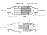
- the gas flow amount is larger in the filter located at a position near to a downstream side end portion of the first exhaust pipe than that in the filter located at a far position (flow rate is faster), and particularly when the second exhaust pipe is located at an opposite side (lower end side), the gas flow amount and the flow rate are more increased.
- the first exhaust pipe and the second exhaust pipe are connected so as to position at upstream side and downstream side sandwiching the casing, so that the flow amount of the central portion of the ceramic filter becomes large (flow rate is fast) and the flow amount of the peripheral portion thereof is small (flow rate is slow).
- the central portion of the filter is largely affected by the gas flown thereinto rather than the peripheral portion thereof.
- a first embodiment of the invention is a ceramic filter comprising an aggregate formed by combining a plurality of filter units each made of a columnar, porous ceramic sintered body having a honeycomb structure and integrally joining them (so as to bundle in a radial direction), in which said aggregate is constituted by a combination of two or more kinds of the filter units.
- filter units having different pressure loss properties it is preferable to use filter units having different pressure loss properties as different kinds of the filter unit.
- the filter unit having the different pressure loss property it is preferable to use a combination of one or more kinds of either units having different cell wall thicknesses, units having different porosities, units having different pore sizes and units having different cell structures.
- a filter unit having a large pressure loss is arranged in a portion having a fast gas flow rate and a filter unit having a small pressure loss is arranged in a portion having a slow gas flow rate, and it is preferable to integrally combine them in the following forms.
- filter units having different strengths can be used filter units having different strengths. It is preferable that a filter unit having a high strength is arranged in the portion having the fast gas flow rate and a filter unit having a low strength is arranged in the portion having a slow gas flow rate, but a case reverse thereto may be conducted.
- filter units having different lengths can be used.
- the combination when a plurality of at least two kinds of columnar filter units are combined in a direction perpendicular to an axial direction at a bundle state, the combination can be properly changed in accordance with the situation of exhaust gas flown into the ceramic filter as compared with a wholly uniform monolith-type ceramic filter or a ceramic filter consisting of a combination of the same kind of filter units, and hence it is possible to conduct the uniform catching and regeneration without causing displacement at positions of the ceramic filter.
- the physical properties such as thermal conductivity and the like can be changed in accordance with the places of the filters and hence the uniform catching and regeneration of the ceramic filter as a whole can be ensured.
- the aggregate as the ceramic filter can be more effectively manufactured by arranging the filter unit having a low pressure loss in places having a small flow amount of the exhaust gas.
- the exhaust gas in the ceramic filter can be guided toward a position of low pressure loss by integrally combining a filter unit(s) having a high pressure loss located at a portion having a relatively fast flow rate and a filter unit(s) having a low pressure loss located at a portion having a relatively slow flow rate; 2 a filter unit(s) being thin in the wall thickness and easy in the pass of the gas is arranged in place(s) having a small flow amount of the exhaust gas; 3 a filter unit(s) having a thick wall thickness is arranged in a portion having a fast gas flow rate, while a filter unit(s) having a thin wall thickness is arranged in a portion having a slow flow rate, whereby the exhaust gas in the ceramic filter can be guided toward place having a low pressure loss; 4 a filter unit(s) having a high porosity is arranged in place having a small flow amount of the exhaust gas; 5 a filter unit(s) having a low porosity is arranged in
- the exhaust gas in the ceramic filter can be guided toward a place having a low pressure loss by combinedly arranging the filter unit having a small pore size in a portion having a relatively fast flow rate and the filter unit having a large pore size in a portion having a relatively slow flow rate.
- the filtering area of the ceramic filter is made large by fining the cell structure of the filter unit, the pressure loss in and after the catching becomes low. Therefore, the uniform catching can be effectively conducted by arranging the filter unit having a high cell density in a portion having a low flow amount of the exhaust gas.
- the filter unit having a large cell density is arranged in the portion having a relatively fast flow rate and the filter unit having a small cell density is arranged in the portion having a relatively slow flow rate, whereby the exhaust gas in the ceramic filter can be guided toward a place in the ceramic filter having a low pressure loss of the exhaust gas.
- filter units having different strengths there can be used filter units having different strengths. That is, a filter unit having a high strength is used in a portion of the ceramic filter subjected to thermal shock, whereby the strength as the aggregate of the ceramic filter can be improved.
- the inventors have further made various experiments for solving the cause of the deterioration of the filter performance. For example, there is made a test for increasing a catalyst carrying amount of the filter. In this case, however, the pressure loss of the filter becomes higher and the progress of the deterioration can not be prevented. Then, temperatures at plural places are measured by inserting a thermocouple into the filter to be regenerated. Contrary to expectation, it has been confirmed that a temperature difference is caused in positions of the filter, for example, between the central portion and outer peripheral portion. That is, the temperature of the filter in the central portion is higher than that of the filter in the outer peripheral portion.
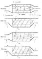
- the temperature is measured by changing a connecting relationship between the filter and the casing as shown in FIG. 12.
- the temperature distribution appearing in the filter differs in accordance with the difference in the connecting position between the exhaust pipe and the casing as shown in FIG. 12, and particularly the filter temperature tends to become high in the portion near to the exhaust pipe. Therefore, when conducting the temperature control of the filter, if it is intended to control the temperature to about 600°C well promoting the reaction of the catalyst, it is confirmed that a portion rendering into a high temperature exceeds 800°C. Also, as the construction of the catalyst itself is examined, it is confirmed that a noble metal used as the catalyst causes sintering (metal changes into large particles) immediately above 800°C and the reactivity becomes bad and the use thereof is impossible.
- the inventors have knowledge that when the ceramic filter is constituted with an aggregate of columnar filter units dividable in a radial direction as mentioned above, it is effective to carry different catalysts on the respective columnar filter units or change a carrying amount of the catalyst on the filter unit.
- a second embodiment of the invention is a ceramic filter comprising an aggregate formed by combining a plurality of columnar filter units each having a honeycomb structure and made of porous ceramic sintered body through a sealing material layer (preferably a sealing material indicating an adhesiveness: adhesive layer) and integrally joining them, in which the aggregate is constituted by combining two or more kinds of the filter units and a catalyst of different carrying amount or different kind is carried on each of the filter units.
- a sealing material layer preferably a sealing material indicating an adhesiveness: adhesive layer
- the different kinds of the filter units carrying the catalyst of different carrying amount or different kind can be used one or more of the filter units having different pressure loss properties, the filter units having different strengths and the filter units having different lengths as mentioned above.
- filter units having different pressure loss properties can be used one or more of units having different thicknesses of cell wall, units having different porosities, units having different pore sizes and units having different cell structures.
- catalysts having different heat resistance or catalytic activities can be used as the different kinds of the catalyst.
- a filter unit carried with a catalyst having a good heat resistance is arranged in a portion having a fast gas flow rate or a large gas flow amount and/or a filter unit carried with a catalyst having a poor heat resistance is arranged in a portion having a slow gas flow rate or a small gas flow amount and they are integrally combined to form a ceramic filter.
- a filter unit carried with a catalyst having a large activity is arranged in a portion having a fast gas flow rate or a large gas flow amount and/or a filter unit carried with a catalyst having a small activity is arranged in a portion having a slow gas flow rate or a small gas flow amount.
- a filter unit having a small carrying amount of a catalyst is arranged in a portion having a fast gas flow rate or a large gas flow amount and/or a filter unit having a large carrying amount of a catalyst is arranged in a portion having a slow gas flow rate or a small gas flow amount.
- the ceramic filter may be an aggregate formed by integrally joining a plurality of filter units each made of columnar and porous ceramic sintered body having a honeycomb structure through a sealing material layer, in which the aggregate is constituted with a combination of two or more different kinds of the filter units and the filter units are an integral combination of a unit not carrying the catalyst and a unit carrying at least one kind of catalysts.
- the filter unit carrying the catalyst is arranged in a portion having a slow gas flow rate or a small flow amount.
- the invention having the above construction has the function and effect as mentioned below. That is, in the invention, all of the filter unit fundamentally combined as the ceramic filter do not carry the same catalyst, but the different catalyst is carried every the filter unit, so that there can be provided a ceramic filter suitable for an exhaust gas purifying apparatus of an automobile causing a deflected gas flowing.
- an example of arranging catalysts having different heat resistances in accordance with positions in the radial direction of the filter or an example of carrying catalysts having different catalytic activities means that the catalyst most suitable in the use of the ceramic filter is selectively attached to the respective position.
- the filter carried with the catalyst having an excellent heat resistance is used in a portion having a fast flow rate or a large gas flow amount of the exhaust gas, whereby the catalyst in a position exposed to the high-temperature portion can be used over a long time.
- the regeneration can be efficiently conducted even in a portion of a relatively low temperature by using the filter carried with the catalyst having a large activity in the portion having a slow gas flow rate or a small gas flow amount.
- the carrying amount of the catalyst may be changed in accordance with the place in the radial direction of the filter (the same catalyst amount may not be carried on the filter).
- the same catalyst amount may not be carried on the filter.
- the filter unit having catalyst weight and density adjusted to a large level in a portion having a relatively low temperature and arrange the filter unit having catalyst weight and density adjusted to a small level in a portion having reversely a relatively high temperature.
- the aggregate of the ceramic filter can be formed by using both a filter unit carried with the catalyst and a filter unit not carried with the catalyst.
- the filter unit having no catalyst can be used in a portion promoting the regeneration of soot without the catalyst at a relatively high temperature, while the filter unit having the catalyst can be used in a portion requiring the catalyst effect at a relatively low temperature.
- the filter unit having the catalyst in a portion having a small flow amount of the exhaust gas and being relatively low in the temperature and reversely arrange the filter unit having no catalyst in a portion having a large flow amount of the exhaust gas and being relatively high in the temperature in the use of the ceramic filter.
- the ceramic filter having the above properties can be interposed between the first and second exhaust pipes to form an exhaust gas purifying apparatus having a high strength and capable of using over a long time.
- a filter unit having a high strength arranged in a portion having a relatively fast flow rate and a filter unit having a low strength arranged in a portion having a relatively slow flow rate are integrally combined, whereby there can be provided a ceramic filter capable of coping with the rapid temperature change of the exhaust gas.
- a filter unit having a low strength arranged in a portion having a relatively fast flow rate and a filter unit having a high strength arranged in a portion having a relatively slow flow rate are integrally combined, whereby there can be provided a ceramic filter capable of coping with the temperature change generated when abnormal burning is caused due to unburnt soot in the portion having the slow flow rate.
- the ceramic filter may be formed by changing a filter length and arranging a filter unit having a short length in a portion having a small catching amount of soot.
- the position of soot amount from front edge face can be made same.
- the aggregate of the filters can promote the catching of soot and regeneration as whole.
- a ceramic filter having a high filtering efficiency, a low pressure loss and excellent heat resistance and thermal conductivity can be provided by using a porous silicon carbide sintered body as a material for the ceramic filter.
- (C) As a third embodiment of the invention, there is proposed an exhaust gas purifying apparatus having a high strength and capable of using over a long time by interposing and arranging various ceramic filters having different properties in an axial direction and/or a radial direction in a casing between first and second exhaust pipes.
- An exhaust gas purifying apparatus 1 for a diesel engine as an embodiment of the invention and a ceramic filter used therefor are explained with reference to FIG. 1 to FIG. 13 below.
- the exhaust gas purifying apparatus 1 shown in FIG. 1 is an apparatus for purifying an exhaust gas discharged from a diesel engine 2 as an internal combustion engine.
- the diesel engine 2 comprises plural cylinders not shown, and each cylinder is connected to a branched part 4 of an exhaust manifold 3 made of a metallic material.
- Each branched part 4 is joined to a main body 5 of the manifold. Therefore, exhaust gas discharged from the each cylinder is collected to the manifold main body.
- first exhaust pipe 6 and a second exhaust pipe 7 each made of a metallic material.
- An end portion of an upstream side of the first exhaust pipe 6 is connected to the manifold main body 5, and a cylindrical casing 8 made of a metallic material is arranged between the first exhaust pipe 6 and the second exhaust pipe 7. That is, an end portion of an upstream side of the casing 8 is connected to an end portion of a downstream side of the first exhaust pipe 6, and an end portion of a downstream side of the casing 8 is connected to an end portion of an upstream side of the second exhaust pipe 7.
- the casing 8 is arranged at an interposing state between the exhaust pipes 6, 7.
- a main application of the ceramic filter 9 is a diesel particulate filter (DPF) for removing diesel particulates in the exhaust gas discharged from the diesel engine.
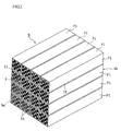
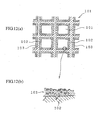
- a block 9 constituting the filter shown in FIG. 2 is formed by bundling a plurality of ceramic filter units F1 having a honeycomb structure so as to combine faces perpendicular to an axial direction with each other and integrally uniting them to form an aggregate (block).
- a filter unit F1 positioned in a central portion of the aggregate is quadratic prism-shaped, an outer size of which is 33 mm x 33 mm x 150 mm.
- quadratic prism-shaped filter units F1 are bundled in 4 rows and 4 columns, i.e. a total of 16 units to form a quadratic prism-shaped aggregate (ceramic filter) of honeycomb filter units as a whole.
- These filter units F1 are preferable to be made of a porous silicon carbide sintered body. Because, the silicon carbide sintered body is excellent in the heat resistance and thermal conductivity as compared with the other ceramics. Of course, sintered bodies of silicon nitride, sialon, alumina, cordierite, mullite and the like can be used as a sintered body other than silicon carbide. Further, as the unit F1 can be used a silicon-containing ceramic formed by compounding metallic silicon with the above ceramic, or a ceramic bonded with silicon or a silicate compound.
- each of these filter units F1 is provided with a honeycomb structure, so that there is an advantage that even when the catching amount of particulates increases, the pressure loss is small.
- each of the filter units F1 are regularly formed plural through-holes 12 having substantially a quadrate at section along an axial direction of the unit.
- the through-holes 12 are partitioned with each other through thin cell walls 13, and an oxidation catalyst consisting of an element of platinum group (e.g. Pt or the like) or the other metal element or an oxide thereof is carried on the cell wall 13.
- a catalyst purifying Ca, HC, Nox or the like may be carried, or a rare earth element, alkaline earth metal, alkali metal, transition metal may be carried.
- opening portions of each through-hole 12 are sealed with a plug 14 (porous silicon carbide sintered body in this embodiment) at either one of end faces 9a, 9b, and viewing the whole of the end faces 9a, 9b, the opening portions and the sealed portions are constructed so as to indicate a checkered pattern.
- a plug 14 porous silicon carbide sintered body in this embodiment
- the filter unit F1 is at a state of constituting with many cells having a quadratic form at section.
- a density of the cells is about 100-400 cells/inch square and a thickness of the cell wall 13 is about 0.05-0.5 mm.
- the cell structure is generally represented by dividing the thickness of the cell wall 13 as a unit of mil (1 mil is 0.0254 mm) by the cell density. That is, the above example is represented by 14/200. Therefore, about a half of many cells are opened at the upstream side end faces 9a, and the remaining half are opened at the downstream side end faces 9b.
- the average pore size is 1 ⁇ m - 50 ⁇ m, preferably about 5 ⁇ m - 20 ⁇ m.
- the average pore size is less than 1 ⁇ m, the clogging of the filter unit F1 due to the deposition of the particulates becomes conspicuous. While, when the average pore size exceeds 50 ⁇ m, fine particulates can not be caught and the filtering ability lowers.
- the porosity of the filter unit F1 is 30% - 80%, preferably 35% - 70%.
- the porosity is less than 30%, the unit becomes too dense and there is a fear that the exhaust gas can not be flown into the interior of the unit.
- the porosity exceeds 80%, the pores in the filter unit F1 becomes too large and there is a fear that the strength becomes weak and the catching efficiency of the particulates lowers.
- the sealing material layer 15 is preferable to have a thickness of about 0.3 mm - 3 mm, further preferably 0.5 mm - 2 mm. When the thickness is exceeds 3 mm, even if the thermal conductivity is high, the sealing material layer 15 is still a large heat resistor and hence the thermal conduction between the filter units F1 is obstructed. Also, a ratio of the filter unit F1 portion occupied in the ceramic filter 9 is relatively decreased to bring about the lowering of the filtering ability. Inversely, when the thickness of the sealing material layer 15 is less than 0.3 mm, the large heat resistor is not formed, but the adhesion property between the filter units F1 is lacking and the ceramic filter 9 is easily broken.
- the sealing material layer 15 is made of, for example, inorganic fibers, an inorganic binder, an organic binder and inorganic particles, and is desirable to be made of an elastic material formed by binding three-dimensionally crossed inorganic fibers and inorganic particles through the inorganic binder and organic binder.
- the inorganic fiber may be used one or more ceramic fibers selected from silica-alumina fibers, mullite fibers, alumina fibers and silica fibers. Among them, the use of the silica-alumina ceramic fibers is desirable. Because, the silica-alumina ceramic fiber is excellent in the elasticity and has an action of absorbing heat stress.
- the content of the silica-alumina ceramic fibers occupied in the sealing material layer 15 is 10% by weight - 70% by weight, preferably 10% by weight - 40% by weight, more preferably 20% by weight - 30% by weight as a solid content.
- the content is less than 10% by weight, the function and effect as the elastic body lower. While, when the content exceeds 70% by weight, not only the thermal conductivity but also the elasticity lower.
- the silica-alumina ceramic fiber is preferable to contain shots of 1% by weight - 10% by weight, preferably 1% by weight - 5% by weight, more preferably 1% by weight - 3% by weight.
- shots of 1% by weight - 10% by weight preferably 1% by weight - 5% by weight, more preferably 1% by weight - 3% by weight.
- the silica-alumina ceramic fiber has a fiber length of 1 mm - 100 mm, preferably 1 mm - 50 mm, more preferably 1 mm - 20 mm.
- the fiber length is less than 1 mm, the elastic structural body can not be formed, while when the fiber length exceeds 100 mm, the fibers are pilled and the dispersibility of the inorganic particles is deteriorated, and further it is difficult to thin the sealing material layer 15 to not more than 3 mm and hence it is not attempted to improve the thermal conduction between the filter units F1.
- the inorganic binder included in the sealing material layer 15 is desirable at least one colloidal sol selected from silica sol and alumina sol. Particularly, it is desirable to select the silica sol. Because, the silica sol is available and easily changes into SiO 2 through firing and is suitable as an adhesive at a high temperature region. Also, the silica sol is excellent in the insulating property.
- the content of the silica sol in the sealing material layer 15 is 1% by weight - 30% by weight, preferably 1% by weight - 15% by weight, more preferably 5% by weight - 9% by weight as a solid content.
- the content is less than 1% by weight, the adhesion strength lowers, while when the content exceeds 30% by weight, the thermal conductivity largely lowers.
- a hydrophilic organic high polymer is preferable, and at least one polysaccharide selected from polyvinyl alcohol, methylcellulose, ethylcellulose and carboxymethyl cellulose is more preferable. Among them, it is desirable to select carboxymethyl cellulose. Because, carboxymethyl cellulose gives a preferable fluidity to the sealing material layer and indicates an excellent adhesiveness at a room temperature region.
- the content of the carboxymethyl cellulose in the adhesive layer is 0.1% by weight - 5.0% by weight, preferably 0.2% by weight - 1.0% by weight, more preferably 0.4% by weight - 0.6% by weight as a solid content. When the content is less than 0.1% by weight, migration can not be sufficiently controlled.
- the term "migration" used herein means a phenomenon that in case of curing the sealing material layer filled between bodies to be adhered, the binder moves accompanied with the removal of the solvent through drying. While, when the content exceeds 5.0% by weight, the organic binder burns out at a higher temperature and the strength of the sealing material layer 15 lowers.
- the inorganic particles included in the sealing material layer 15 is preferable an elastic material using one or more inorganic powder or whisker selected from silicon carbide, silicon nitride and boron nitride.
- silicon carbide, silicon nitride and boron nitride are very large in the thermal conductivity and contribute to improve the thermal conduction owing to the inclusion on a surface of the ceramic fiber or a surface of the colloidal sol and interiors thereof.
- the inorganic powder of the carbide and nitride it is desirable to select silicon carbide powder. Because, silicon carbide is very high in the thermal conductivity and has a property of being easily familiar with the ceramic fiber. Further, the filter unit F1 as a body to be adhered is the same kind, i.e. porous silicon carbide in this embodiment.
- the content of silicon carbide powder is 3% by weight - 80% by weight, preferably 10% by weight - 60% by weight, more preferably 20% by weight - 40% by weight as a solid content.
- the content is less than 3% by weight, the thermal conductivity of the sealing material layer 15 lowers and hence the sealing material layer 15 becomes still a large heat resistor. While, when the content exceeds 80% by weight, the adhesion strength at high temperatures lowers.
- the particle size is 0.01 ⁇ m - 100 ⁇ m, preferably 0.1 ⁇ m - 15 ⁇ m, more preferably 0.1 ⁇ m - 10 ⁇ m.
- the particle size exceeds 100 ⁇ m, the adhesion force and thermal conductivity lower, while when the particle size is less than 0.01 ⁇ m, the cost of the sealing material layer 15 increases.
- the exhaust gas is fed from a side of the upstream side end face 9a. That is, the exhaust gas flown from the first exhaust pipe 6 first flows into the cell opening to the upstream side end face 9a of the ceramic filter. Then, the exhaust gas passes through the cell wall 13 and flows into the adjoining other cell (i.e. adjoining cell at a side opening to the downstream side end face 9b), which is discharged from the opening downstream side end face 9b. In such a flowing of the gas, particulates included in the exhaust gas (diesel particulate) can not pass through the cell wall 13, so that they are trapped on the surface of the cell wall 13 as they are. As a result, the purified exhaust gas is discharged from the downstream side end face 9b of each filter unit F1. Then, the purified exhaust gas passes through the second exhaust pipe 7 and is finally discharged into air.
- the particulates trapped by the cell wall 13 are burnt out by the action of the catalyst when the internal temperature of the ceramic filter 9 reaches to a given temperature.
- the ceramic filter (A) according to the invention is described with respect to an example of the aggregate formed by combining filter units F1 having different properties in the radial direction of the filter, e.g. different pressure loss properties, but the invention is not limited to this example.
- the pressure loss property when the exhaust gas passes through the cell wall 13 is considered as follows.
- the pressure loss when the diesel exhaust gas passes through the filter unit F1 can be shown in FIG. 4.
- ⁇ P4 is a resistance when the diesel particulates pass through the cell wall 13 of the filter unit F1 after the deposition, which is a value corresponding to 2-3 times or more of the initial pressure loss.
- filter units F1 cell wall thickness, porosity, pore size, cell structure
- the filter unit F1 having a large pressure loss is arranged in a portion having a fast gas flow rate and the filter unit F1 having a small pressure loss is arranged in a portion having a slow gas flow rate, and they are integrally combined. Concrete examples thereof are mentioned as follows.
- filter units having different strengths can be used as an example of different kinds of filter units F1.
- a filter unit having a high strength is arranged in the portion having a fast gas flow rate and a filter unit having a low strength is arranged in the portion having a slow gas flow rate in accordance with the specification of the engine and the regeneration system, or the arrangement of these filter units is opposite, so that the combination thereof can be properly selected.
- honeycomb filters having different lengths can be used as an example of different kinds of the filter units F1.
- the ceramic filter (B) according to the invention is described with respect to an example of the aggregate formed by combining filter units F1 having different kinds of catalyst carried on the filter unit F1 and/or different carrying amounts, but the invention is not limited to this example.
- the catalyst formed on the each filter unit F1 is described below.
- the catalyst used in the invention (B) is preferable to be a rare earth oxide-containing alumina film 17 separately coating the surface of each SiC particle 16 with respect to SiC particles 16 of SiC sintered body constituting the cell walls 13 partitioning each cell of the filter unit F1.
- alumina has a high specific surface area and is suitable as a catalyst carrying film. Particularly, it is desirable to develop filter units F1 stably acting at a higher temperature and having a high heat resistance at the present time, and the alumina film 17 is required to have a higher heat resistance accompanied therewith.
- the shape of each alumina particle is rendered into a small fiber and 2 a rare earth oxide such as ceria (cerium oxide) or the like is included therein.
- a rare earth oxide such as ceria (cerium oxide) or the like.
- the alumina film 17 covering the surface of each SiC particle in the filter unit F1 shows a hair implant structure that alumina particles stand up in form of small fibers at a microscopic section.
- the heat resistance is considerably improved because the contact points between adjoining alumina small fibers is reduced.
- the heat resistance is improved by adding ceria or the like. This is due to the fact that a new compound is formed on the surfaces of the crystal particles constituting the alumina film 17 to obstruct the growth of alumina particles.
- SiC or SiO 2 existing on an extreme surface layer thereof feeds Si in the heat treatment to shut off a mass transfer course, whereby the heat resistance is improved. According to the inventors' studies, it is confirmed that when SiC is intentionally treated at a high temperature to form an oxide, the heat resistance is further improved.
- the regeneration property of the alumina film 17 is described below.
- the alumina film 17 is obtained by adding a rare earth oxide such as ceria (CeO 2 ) or lanthana (La 2 O 3 ) in an amount of about 10-80 mass%, preferably 20-40 mass% based on Al 2 O3 and uniformly dispersing the oxide into the surface or interior of the alumina film 17.
- a rare earth oxide such as ceria (CeO 2 ) or lanthana (La 2 O 3 )
- the feeding of oxygen into the exhaust gas is activated by an action of adjusting oxygen concentration inherent to ceria, whereby the efficiency of burning and removing "soot (diesel particulates) adhered to the filter unit F1 is improved and hence the regeneration ratio of the filter unit F1 is considerably improved. Also, the durability of the filter unit F1 can be improved.
- the rare earth oxide such as ceria or the like improves the heat resistance of alumina but also plays a role of adjusting the oxygen concentration on the surface of the filter unit F1.
- hydrocarbon or carbon monooxide existing in the exhaust gas is removed by oxidation reaction and NOx is removed by reducing reaction.
- Ceria added to the catalyst is relatively low in the redox potential of Ce 3+ and Ce 4+ and reversibly promotes a reaction of 2CeO 2 ⁇ Ce 2 O 3 + 1/2O 2 . That is, when the exhaust gas renders into a rich region, the above reaction proceeds to the right to feed oxygen into an atmosphere, while when it renders into a lean region, the reaction proceeds to the left to occlude extra oxygen in the atmosphere.
- the ceria adjusts the oxygen concentration in the atmosphere and takes an action of widening a width of an air-fuel ratio so as to efficiently remove hydrocarbon, carbon monooxide or NOx.
- the catalyst containing no CeO 2 oxidizes soot by activating oxygen in the exhaust gas. This reaction is poor in the efficiency because oxygen in the fluid should be activated.
- the catalyst containing CeO 2 feeds oxygen by the following reaction formula: CeO 2 ⁇ CeO 2-x + ⁇ /2O 2 That is, oxygen discharged into the atmosphere and oxygen in the exhaust gas are activated by the catalyst (noble metal) and reacted with soot (carbon) to form CO 2 (CeO 2-x is oxidized to original CeO 2 ). Also, CeO 2 and soot directly contact with each other, so that even if the oxygen amount discharged is small, the soot can be efficiently oxidized.
- CeO 2 increases OSC (oxygen storing capacity) owing to the carrying of the catalyst (noble metal). Because, the catalyst (noble metal) activates oxygen in the exhaust gas and activates oxygen on the surface of CeO 2 near to noble metal, and the OSC is increased.
- the rare earth oxide it is preferable to use a composite oxide of rare earth element and zirconium in addition to the above single oxide (CeO 2 ). In this case, it is considered that when zirconium oxide is included in the rare earth oxide, the grain growth of the rare earth oxide is suppressed to improve the controlling property of oxygen concentration.
- the particle size is preferably about 1-30 nm, more preferably 2-20 nm.
- the particle size is less than 1 nm, it is difficult to produce the composite oxide.
- the particle size exceeds 30 nm, the particles easily cause the sintering and hence the surface area of the particles becomes small and the contact area with the exhaust gas becomes small and there is a problem that the activity is weak. Further, there is feared that the pressure loss in the pass of the exhaust gas becomes large.
- a noble metal or an element selected from elements of Group VIa and VIII in the Periodic Table as a catalyst.
- an element are concretely mentioned platinum (Pt), palladium (Pd), rhodium (Rh), nickel (Ni), cobalt (Co), molybdenum (Mo), tungsten (W), cerium (Ce), copper (Cu), vanadium (V), iron (Fe), gold (Au), silver (Ag) and the like.
- At least one element selected from Pt, Au, Ag and Cu as a noble metal, Mo, W as an element of Group VIa, Fe, Co, Pd, Rh, Ni as an element of Group VIII and V, Ce as an element other the above in the Periodic Table or a compound thereof may be carried on the alumina film 17.
- a binary alloy or a ternary alloy based on a combination of the above elements is used as the compound. It is advantageous to use such an alloy together with the rare earth oxide such as ceria, lanthana or the like acting as a co-catalyst as mentioned above.
- the thus formed filter unit F1 is less in the deterioration due to poisoning (lead poisoning, phosphorus poisoning, sulfur poisoning) and small in the thermal deterioration and excellent in the durability.
- compounds based on a combination with the other element may be used in addition to the alloy of the above combination.
- the binary alloy includes Pt/Pd, Pt/Rh, Pt/Ni, Pt/Co, Pt/Mo, Pt/W, Pt/Ce, Pt/Cu, Pt/V, Pt/Fe, Pt/Au, Pt/Ag, Pd/Rh, Pd/Ni, Pd/Co, Pd/Mo/ Pd/W, Pd/Ce, Pd/Cu, Pd/V, Pd/Fe, Pd/Au, Pd/Ag, Rh/Ni, Rh/Co, Rh/Mo, Rh/W, Rh/Ce, Rh/Cu, Rh/V, Rh/Fe, Rh/Au, Rh/Ag, Ni/Co, Ni/Mo, Ni/W, Ni/Ce, Ni/Cu, Ni/V, Ni/Fe, Ni/Au, Co/Mo, Co/W, Co/Ce, Co/Cu, Co/V, Co/Fe, Co/AAg, Co/Mo,
- the ternary alloy there are Pt/Pd/Rh, Pt/Pd/Ni, Pt/Pd/Co, Pt/Pd/Mo, Pt/Pd/W, Pt/Pd/Ce, Pt/Pd/Cu, Pt/Pd/V, Pt/Pd/Fe, Pt/Pd/Au, Pt/Pd/Ag, Pt/Rh/Ni, Pt/Rh/Co, Pt/Rh/Mo, Pt/Rh/W, Pt/Rh/Ce, Pt/Rh/Cu, Pt/Rh/V, Pt/Rh/Fe, Pt/Rh/Au, Pt/Rh/Ag, Pt/Ni/Co, Pt/Ni/Mo, Pt/Ni/W, Pt/Ni/Ce, Pt/Ni/Cu, Pt/Ni/V, Pt/Ni/Fe, Pt/Ni/Cu
- an impregnation method, an evaporation drying method, an equilibrium adsorption method, incipient wetness method or a spraying method is advantageously applicable.
- the incipient wetness method is advantageous.
- This method is a method wherein an aqueous solution containing a given amount of the catalyst is added dropwise to the filter unit F1 and the impregnation of the catalyst into pores of the filter unit F1 is stopped at a time of uniformly and slightly wetting the surface of the carrier (incipient state) and thereafter the drying and firing are conducted. That is, the dropwise addition of the catalyst-containing solution on the surface of the filter unit F1 is carried out by using a bullet or an injection syringe.
- the carrying amount of catalyst can be controlled by adjusting the concentration of the solution.
- a feature of the method of carrying the catalyst on the filter unit F1 in this embodiment lies in that the alumina film 17 containing the rare earth oxide is formed on the irregular surface of the filter unit F1 by a sol-gel process. Particularly, the alumina film 17 containing the rare earth oxide is coated onto each surface of SiC particles forming the cell wall 13 through the impregnation of the solution. Then, the alumina film 17 is changed into an alumina film (carrier film) 17 showing a hair implant structure that ceria-dispersed alumina stands up in form of small fibers at a microscopic section through a step of treated with hot water after the calcining, and then a given amount of the catalyst is adsorbed and fixed onto the surface of the alumina film 17.
- oxidation is carried out by heating at 800-1600°C for 5-100 hours in order to feed a required amount of Si promoting a chemical bonding with alumina on each surface of SiC particles 16. If sufficient oxide film is existent on the surface of SiC particles 16, this step may be naturally omitted.
- SiC sintered body itself contains about 0.8 mass% of SiO 2 .
- the temperature is lower than 800°C, the oxidation reaction hardly occurs, while when it exceeds 1600°C, the oxidation reaction extremely proceeds and the lowering of the strength in the filter is caused.
- a recommendable condition is 1000-1500°C and 5-20 hours. In this condition, SiO 2 enough to feed Si can be formed on the surface, and also the porosity and pore size in the filter unit F1 are not changed and the pressure loss property is not damaged.
- a treatment coating the rare earth oxide containing alumina film 17 is carried out by impregnating each surface of the SiC particles 16 constituting the cell wall 13 with a solution of a metal compound containing aluminum and rare earth element, e.g. a mixed aqueous solution of aluminum nitrate and cerium nitrate or the like through a sol-gel process.
- a metal compound containing aluminum and rare earth element e.g. a mixed aqueous solution of aluminum nitrate and cerium nitrate or the like through a sol-gel process.
- a metal inorganic compound and a metal organic compound As a starting metal compound are used a metal inorganic compound and a metal organic compound.
- the metal inorganic compound are used Al(NO 3 ) 3 , AlCl 3 , AlOCl, AlPO 4 , Al 2 (SO 4 ) 3 , Al 2 O 3 , Al(OH) 3 , Al and the like.
- Al(NO 3 ) and AlCl 3 are preferable because they are easily soluble in alcohol, water or the like and are easy in the handling.
- the metal organic compound As the metal organic compound are mentioned a metal alkoxide, a metal acetylacetonate and a metal carboxylate.
- cerium-containing solution in the above mixed aqueous solution are used Ce(NO 3 ) 3 , CeCl 3 , Ce 2 (SO 4 ) 3 , CeO 2 , Ce(OH) 3 , Ce 2 (CO 3 ) 3 and the like.
- a solvent in the above mixed solution is used at least one selected from water, alcohol, diol, polyvalent alcohol, ethylene glycol, ethylene oxide, triethanolamine, xylene and the like.
- hydrochloric acid, sulfuric acid, nitric acid, acetic acid or fluoric acid may be added as a catalyst.
- at least one element selected from Ce, Li, K, Ca, Sr, Ba, La, Pr, Nd, Si and Zr or a compound thereof other than oxide (nitrate, chloride, sulfate, hydroxide or carbonate) may be added to the starting material in addition to the rare earth oxide.
- a preferable metal compound in this embodiment mention may be made of Al (NO 3 ) 3 and Ce(NO 3 ) 3 . They are dissolved in the solvent at a relatively low temperature and is easy in the preparation of the starting solution. Also, 1,3-butane diol is recommended as a preferable solvent. A first reason of the recommendation lies in that the viscosity is adequate and a gel film having a proper thickness may be formed on the SiC particles 16 at a gel state. A second reason is due to the fcat that this solvent forms a metal alkoxide in the solution and a metal oxide polymer having oxygen-metal-oxygen bond or a precursor of metal oxide gel may be easily formed.
- the amount of Al(NO 3 ) 3 is desirable to be 10-50 mass%. When it is less than 10 mass%, the alumina amount having a surface area for maintaining the activity of the catalyst for a long time can not be carried, while when it exceeds 50 mass%, an amount of heat generation becomes large in the dissolution and the gelation is easily caused.
- the amount of Ce(NO 3 )3 is preferable to be 1-30 mass%. When it is less than 1 mass%, the oxidation of the soot can not be promoted, while when it exceeds 30 mass%, the grain growth of CeO 2 occurs after the firing.
- the mixing ratio of Al(NO 3 ) 3 to Ce (NO 3 ) 3 is preferable to be 10:2. As Al(NO 3 ) 3 becomes richer, the dispersibility of CeO 2 particles after the firing can be improved.
- the temperature is desirable to be 50-130°C.
- the solubility of the solute is low, while when it exceeds 130°C, the reaction is violently promoted to cause gelation and the use of the applying solution is impossible.
- the stirring time is desirable to be 1-9 hours. When it is within the above range, the viscosity of the solution is stable.
- ZrO(NO 3 ) 2 or ZrO 2 is used as a zirconium source for producing a composite oxide with zirconium or a solid solution in addition to the above example.
- the above substance is dissolved in water or ethylene glycol to form a mixed solution and dried and fired to form the above composite oxide.
- the solution of the above metal compound is sufficiently penetrated into all pores between SiC particles 16 in the cell wall 13.
- the deaeration apparatus may be used a vacuum pump or the like in addition to an aspirator. By using such an apparatus can be removed air from the pores in the cell wall 13 and hence the solution of the metal compound can be well fed onto the each surface of SiC particles 16.
- This step is a treatment that volatile components such as NO 2 and the like are removed by evaporation and the solution is gelated and fixed to the surfaces of SiC particles 16 and at the same time extra solution is removed, which is carried out by heating at 120-170°C for about 2 hours.
- the heating temperature is lower than 120°C, the volatile components hardly evaporate, while when it exceeds 170°C, the gelated film thickness become nonuniform.
- This step is a calcining treatment for removing residual components to form an amorphous alumina film 17. Concretely, it is desirable to heat at a temperature of 300-500°C. When the calcining temperature is lower than 300°C, the residual organic mass is hardly removed, while when it exceeds 500°C, Al 2 O 3 is crystallized and hence boehmite of small fibrous protrusion can not be formed.
- This step is a treatment that the calcined filter unit F1 is immersed in hot water for forming the alumina film 17 having a specified structure inherent to the above embodiment.
- the particles on the surface of the amorphous alumina film 17 is immediately discharged into the solution at a sol state by a deflocculation action and also boehmite particles produced by hydration are aggregated in form of small fibrous protrusions and form a stable state against deflocculation.
- the rare earth oxide-containing alumina adhered to each surface of the SiC particles 16 is stood up in form of small fibers (protrusions) by the hot water treatment, which forms a rough surface indicating the hair implant structure. Therefore, there is formed the alumina film 17 having a high specific surface area.
- the sintering of alumina mainly proceeds through surface diffusion, and when it is changed into ⁇ -alumina phase, the specific surface area rapidly reduces.
- silica is enclosed in the alumina particles, it is considered that hole sites of alumina are clogged with silica in the course of the heat treatment or silica moves toward surfaces of needle-like particles to control the surface diffusion or the sintering of the particles.
- the temperature is desirable to be 50-100°C.
- the hydration of the amorphous alumina film 17 does not proceed and the boehmite of small fibrous protrusion is not formed.
- water is evaporated and this step is hardly maintained over a long time.
- the treating time is desirable to be not less than 1 hour. When it is less than 1 hour, the hydration of the amorphous alumina is insufficient.
- a treatment for dehydrating boehmite produced through hydration to form alumina crystal is conducted.
- the firing temperature is preferable to be 500-1000°C. When the temperature is lower than 500°C, the crystallization does not proceed, while when it exceeds 1000°C, the sintering proceeds much and there is a tendency of lowering the surface area.
- the carrying amount of the catalyst is determined by adding dropwise and impregnating the aqueous solution containing Pt or the like by a water absorbing amount of the filter unit F1 so as to slightly wet the surface thereof.
- the water absorbing amount held by the filter unit F1 means that when the measured value of the water absorbing amount of a dry carrier is 22.46 mass%, if the carrier has a mass of 110 g and a volume of 0.1631, the carrier absorbs 24.79/l of water.
- a starting material of Pt for example, a solution of dinitrodiamine platinum nitrate ([Pt(NH 3 ) 2 (NO 2 ) 2 ]HNO 3 , Pt concentration: 4.53 mass%).
- the aqueous solution of dinitrodiamine platinum nitrate adjusted to a given amount as mentioned above is added dropwise to both end faces of the filter unit F1 at constant intervals through a pipette. For example, 40-80 droplets are added every one-side face at constant intervals, whereby Pt is uniformly dispersed and fixed onto the surface of the alumina thin film 3 covering the filter unit F1.
- the filter unit F1 is used as a diesel particulate filter (hereinafter abbreviated as DPF simply). This unit itself has only a function of catching particulates (floating particular substance: PM) with the cell wall 13, but when the catalyst is carried thereon, hydrocarbon and carbon monooxide in the exhaust gas can be oxdized.
- DPF diesel particulate filter
- the filter unit F1 is preferable to apply to a system for particularly treating a diesel exhaust gas, whereby the following functions can be expected:
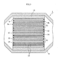
- the thus obtained ceramic filter 9 is wound with a heat insulating material 10, and then the ceramic filter 9 is placed in a casing 8 at this state, and a first exhaust pipe 6, the casing 8 and a second exhaust pipe 7 are arranged in this order.
- casings 8a-8d having four kinds of pipe arrangements as shown in FIG. 5 is fed an exhaust gas from a diesel engine for a constant time. After the catching for 10 hours, the ceramic filter 9 is taken out and cut to observe visually.
- soot 16 is stored in the each kind of the casings 8a, 8b, 8c and 8d as shown in FIG. 5.
- the first exhaust pipe 6 and the second exhaust pipe 7 are arranged in a central portion of the casing 8 at section, so that a greater part of the soot 16 is stored in the central portion of the ceramic filter 9.
- the first exhaust pipe 6 and the second exhaust pipe 7 are arranged on either one side of the peripheral edge portion of the casing 8, so that a greater part of the soot 16 is stored on an elongated line of the exhaust pipe toward the peripheral edge portion of the ceramic filter 9 at section.
- the first exhaust pipe 6 is arranged in the central portion of the casing 8 at section, while the second exhaust pipe 7 is arranged in the peripheral edge portion of the casing 8 at section, so that a greater part of the soot is stored in the central portion of the ceramic filter 9 and the peripheral edge portion arranging the second exhaust pipe.
- the first exhaust pipe 6 is positioned in an upper peripheral portion of the casing 8, while the second exhaust pipe 7 is positioned in a lower peripheral portion of the casing 8 and is not opposed to the first exhaust pipe 6, so that a greater part of the soot 16 is stored in portions of the ceramic filter 9 corresponding to the arranged positions of the first exhaust pipe 6 and the second exhaust pipe 7.
- the storing amount of the soot 16 is proportional to a flowing amount of a gas.
- the filter unit F1 positioned near to the downstream side end of the first exhaust pipe is faster in the incoming gas rate as compared with the filter unit F1 located far away therefrom (the amount is larger), and also if the upstream side end of the second exhaust pipe is located opposite to the same filter, the gas rate in the filter at this position more increases (the amount becomes larger).
- the first exhaust pipe and the second exhaust pipe are connected to the central portion of the casing as shown in FIG. 5(a).
- the ceramic filter 9 therefore, there can be another region producing the difference of the flow rate between the central portion of 4 units and the peripheral portion of 12 units.
- comparative tests are carried out by applying various kinds of filters to the two regions.
- Example 1-1 the ceramic filter 9 is basically prepared in the same manner as the reference example.
- a ceramic filter 9 of 16 filters in total is prepared by using two kinds of SiC filter and cordierite filter as shown in Table 1 and arranging 12 commercially available cordierite filters in the peripheral portion and 4 SiC filters in the central portion.
- the thermal conductivity of cordierite is 2 W/mk
- the thermal conductivity of SiC is 70 W/mk.
- the thus obtained ceramic filter 9 is wound with a heat insulating material 10 and received in a casing 8 at this state, and then the exhaust gas of the engine is fed for a constant time as shown in the reference example. After the catching for 10 hours, the ceramic filter 9 is taken out and cut to conduct visual observation. As a result, the storing amount at the peripheral portion becomes smaller than that at the central portion as shown in FIG. 6(a).
- a new ceramic filter 9 is provided and the exhaust gas is fed thereto. After the catching and regeneration are repeated 100 times, the ceramic filter 9 is taken out to conduct the visual observation. As a result, no crack is observed in the filter units F1. Also, the average regeneration ratio of the ceramic filter 9 is as high as 95%, and no soot 16 is existent as visually observed after the cutting.
- the ceramic filter 9 is basically prepared in the same manner as in the reference example.
- a ceramic filter 9 is prepared by using 16 SiC filter units as shown in Table 1.
- a ceramic filter 9 of 16 filters in total is prepared by using two kinds of SiC filter and cordierite filter and arranging 4 cordierite filters in the central portion and 12 SiC filters in the outer peripheral portion.
- the thus obtained ceramic filter 9 is wound with a heat insulating material 10 and received in a casing 8 at this state, and the exhaust gas of the engine is fed for a constant time as shown in the reference example. After the catching for 10 hours, the ceramic filter 9 is taken out and cut to conduct visual observation. As a result, in Comparative Examples 1-1 and 1-2, the storing amount in the peripheral portion is made small likewise Example 1-1 as shown in FIG. 6(a).
- Example 1-1 Comparative Example 1-1 Comparative Example 1-2 Central portion Peripheral portion Central portion Peripheral portion Central portion Peripheral portion Filter unit SiC Cordierite SiC SiC Cordierite SiC Cell Structure (mill/cell number) 14/200 14/200 14/200 14/200 14/200 14/200 14/200 Porosity of filter 42% 42% 42% 42% 42% 42% 42% Pore size of filter 10 ⁇ m 10 ⁇ m 10 ⁇ m 10 ⁇ m 10 ⁇ m 10 ⁇ m 10 ⁇ m 10 ⁇ m 10 ⁇ m Pressure loss (PMOg/L 13m/s) 10 8 10 10 8 10 Average bending load 350kgf/cm 2 25kgf/cm 2 350kgf/cm 2 350kgf/cm 2 25kgf/cm 2 350kgf/cm 2 Regeneration
- PMOg/L 13m/s Pressure loss
- the ceramic filter 9 is basically prepared in the same manner as in the reference example.
- the filters are prepared by changing molds to adjust a thickness of cell wall 13 in the SiC filter unit or cell number as shown in Table 2 and by changing a compounding ratio of starting materials to adjust a porosity and a pore size as shown in Table 3.
- the ceramic filter 9 is prepared by setting 12 filters to the peripheral portion and setting 4 filters to the central portion as shown in Table 4.
- the thus obtained ceramic filter 9 is wound with a heat insulating material 10 and received in a casing 8, and an exhaust gas of an engine is fed for a given time as shown in the reference example. After the catching for 10 hours, the filter is taken out and cut to conduct visual observation. The results are also shown in Table 4.
- Example 2-2 Substrate A Substrate C 1.4 Fig. 6(b) 90% absence Example 2-3 Substrate A Substrate D 1.6 Fig. 6(d) 82% presence Comparative Example 2-1 Substrate A Substrate A 1.0 Fig. 6(a) 85% presence Example 2-4 Substrate H Substrate G 1.1 Fig. 6(b) 88% absence Example 2-5 Substrate H Substrate A 1.2 Fig. 6(b) 92% absence Example 2-6 Substrate H Substrate F 1.4 Fig. 6(b) 88% absence Example 2-7 Substrate H Substrate E 1.6 Fig.
- the ceramic filter 9 is basically prepared in the same manner as in the reference example. Two kinds of SiC filters having different strengths are used in Example 3-1 as shown in Table 5. In order to change the strength, a higher firing temperature is set to 2300°C - 3 hr, and a lower firing temperature is set to 2100°C - 2 hr. The strength is measured by a three-point bending test described in JIS R1625. In this case, a lower spun is set to 135 mm, and a head speed is set to 0.5 mm/sec. This test is carried out 20 times, and the ceramic filter 9 is prepared by selecting filters from the same production lot. In this case, the ceramic filter 9 is prepared by setting 12 SiC filters having an average bending load of 250 kg/cm 2 to the peripheral portion and 4 SiC filters having an average bending load of 350 kg/cm 2 to the central portion.
- the thus obtained ceramic filter 9 is wound with a heat insulating material 10 and received in a casing 8, and an exhaust gas of an engine is fed for a given time as shown in the reference example. After the catching for 10 hours, the filter is taken out and cut to conduct visual observation. As a result, the storing amount in the peripheral portion of the filter becomes smaller than that in the central portion as shown in FIG. 6(a).
- the ceramic filter 9 is basically prepared in the same manner as in the reference example.
- the ceramic filter 9 is prepared by using 16 SiC filters having a standard average bending load of 250 kg/cm 2 as shown in Table 5.
- the ceramic filter 9 is prepared by using 4 SiC filter having an average bending load of 250 kg/cm 2 in the central portion and 12 SiC filters having a standard average bending load of 350 kg/cm 2 in the peripheral portion.
- the thus obtained ceramic filter 9 is wound with a heat insulating material 10 and received in a casing 8, and an exhaust gas of an engine is fed for a given time as shown in the reference example. After the catching for 10 hours, the filter is taken out and cut to conduct visual observation. As a result, even in Comparative Examples 3-1, 3-2, the storing amount in the peripheral portion becomes smaller than that in the central portion as shown in FIG. 6 (a) .
- the catching and regeneration are repeated by utilizing an engine having a slow gas flow rate in the regeneration.
- Example 4-1 is an example that a ceramic filter 9 is basically prepared in the same manner as in Example 3. In Example 4-1, however, the ceramic filter 9 is prepared by using two kinds of SiC filters having different strengths as shown in Table 6.
- the thus obtained ceramic filter 9 is wound with a heat insulating material 10 and received in a casing 8, and an exhaust gas of an engine is fed for a given time as shown in the reference example. After the catching for 10 hours, the ceramic filter 9 is taken out and cut to conduct visual observation. As a result, the storing amount in the peripheral portion becomes smaller than that in the central portion as shown in FIG. 6(a).
- the ceramic filter 9 is basically prepared in the same manner as in the reference example.
- the ceramic filter 9 is prepared by using 16 SiC filters having a standard average bending load of 250 kg/cm 2 as shown in Table 6.
- the ceramic filter 9 is prepared by using 4 SiC filters having an average bending load of 250 kg/cm 2 in the central portion and 12 SiC filters having a standard average bending load of 350 kg/cm 2 in the peripheral portion.
- the thus obtained ceramic filter 9 is wound with a heat insulating material 10 and received in a casing 8, and an exhaust gas of an engine is fed for a given time as shown in the reference example. After the catching for 10 hours, the filter is taken out and cut to conduct visual observation. As a result, even in Comparative Examples 4-1, 4-2, the storing amount in the peripheral portion becomes smaller than that in the central portion as shown in FIG. 6 (a) .
- Example 5-1 the ceramic filter 9 is basically prepared in the same manner as in the reference example. In Example 5-1, however, there are used two kinds of SiC filter units F1 having different lengths as shown in Table 7. In this case, the ceramic filter 9 is prepared by using 4 SiC filters having a standard length of 150 mm in the central portion and 12 SiC filters of 130 mm in the peripheral portion.
- the thus obtained ceramic filter 9 is wound with a heat insulating material 10 and received in a casing 8, and an exhaust gas of an engine is fed for a given time as shown in the reference example. After the catching for 10 hours, the filter is taken out and cut to conduct visual observation. As a result, soot is stored at substantially the same positions in the central portion and the peripheral portion of the filters as shown in FIG. 7(a).
- the ceramic filter 9 is basically prepared in the same manner as in the reference example. In Comparative Example 5-1, however, the ceramic filter 9 is prepared by using 16 SiC ceramic filters having a standard length of 150 mm as shown in Table 7. In Comparative Example 5-2, the ceramic filter 9 is prepared by forming the peripheral portion with 12 SiC filters having a standard length of 150 mm and forming the central portion with 4 SiC filters having a length of 130 mm.
- the thus obtained ceramic filter 9 is wound with a heat insulating material 10 and received in a casing 8, and an exhaust gas of an engine is fed for a given time as shown in the reference example. After the catching for 10 hours, the filter is taken out and cut to conduct visual observation.
- the storing amount in the peripheral portion becomes smaller than that in the central portion as shown in FIG. 6(a).
- Comparative Example 5-2 the storing amount in the peripheral portion is smaller than that in the central portion as shown in FIG. 7(b), and the difference is large as compared with FIG. 6(a).
- Example 5-1 Comparative Example 5-1 Comparative Example 5-2 Central portion Peripheral portion Central portion Peripheral portion Central portion Peripheral portion Filter unit SiC SiC SiC SiC SiC Cell structure (mill/cell number) 14/200 14/200 14/200 14/200 14/200 14/200 14/200 14/200 Porosity of filter 42% 42% 42% 42% 42% 42% Pore size of filter 10 ⁇ m 10 ⁇ m 10 ⁇ m 10 ⁇ m 10 ⁇ m 10 ⁇ m 10 ⁇ m Pressureloss (PM0g/L,13m/s) 10 10 10 10 10 10 10 10 10 10 10 10 10 10 Average bending load 350 kgf/cm 2 350 kgf/cm 2 350 kgf/cm 2 350 kgf/cm 2 350 kgf/cm 2 350 kgf/cm 2 total length 150mm 130mm 150mm 150mm 130mm 150mm regeneration ratio 90% 85% 70%
- the catching and regeneration can be conducted more uniformly.
- a porous metal filter or a filter using ceramic fibers can be used as a filter.
- the pore distribution can be made broad instead of sharp. In this case, low pressure loss in the catching is obtained.
- Example 6-1 Comparative Example 6-1 and Comparative Example 6-2
- the catalyst having a good heat resistance is used by including 10% of a rare earth oxide such as CeC 2 .
- the distinction between the good and poor heat resistances in the catalyst is judged by observing the change amount of specific surface area after the heat treatment at 1200°C as shown in FIG. 9.
- the regeneration ratio of the ceramic filter temperature difference between the central portion and the peripheral portion of the filter to be measured every each filter unit F1 in the ceramic filter and the durability (regeneration ratio in the regeneration of 10 times). The results are also shown in Table 8.
- each of the example and the comparative examples shows a high value of not less than 90% at initial stage.
- the regeneration ratio after the use of 10 times is apparently high in Comparative Example 6-1 having a heat resistance, but the next value is Example 6-1 instead of Comparative Example 6-3.
- Example 6-1 shows a low value of the temperature difference as a whole as compared with the comparative examples. That is, the filter provided with the catalyst having a high heat resistance is arranged in the portion having a high regeneration temperature, so that the regeneration ratio is high after the use of 10 times.
- This example is carried out for confirming the action and effect of the ceramic filters prepared by using filters carried with catalysts having different active temperatures. That is, each of the ceramic filters produced under conditions shown in Table 9 (Example 7-1, Comparative Example 7-1, Comparative Example 7-2, Comparative Example 7-3) is attached to an exhaust gas purifying apparatus of a diesel automobile to conduct the purification test. Moreover, the distinction of the catalysts having different active temperatures is judged by observing a relationship between regeneration temperature and regeneration ratio as shown in FIG. 10.
- a catalyst having a high-temperature activity means that when an initial filter after the provision of the catalyst (low-temperature active filter capable of well regenerating even at a low active temperature) is subjected to a heat treatment at 800°C in an oxidizing atmosphere for 3 hours to lower the activity of the catalyst, whereby the regeneration can not be sufficiently conducted unless the active temperature is high.
- this test are examined the regeneration ratio of the ceramic filter (aggregate) and the temperature difference between the central portion and the peripheral portion of the ceramic filter to be measured every each filter unit F1. The results are shown in Table 9.
- Example 7-1 and Comparative Example 7-1 show a high value of not less than 90% from an initial stage.
- the ceramic filter of Comparative Example 7-3 in which the same ceramic filters as in Example 7-1 are arranged in an opposite combination between the central portion and the peripheral portion shows the regeneration ratio lower than that of Example 7-1 because the activity in the peripheral portion is bad.
- each of the ceramic filters produced under conditions shown in Table 10 (Example 8-1, Example 8-2, Comparative Example 8-1, Comparative Example 8-2, Comparative Example 8-3) is attached to an exhaust gas purifying apparatus to conduct the purification test.
- the carrying amount of the catalyst is determined as follows. At first, the ceramic filter is divided into two regions of 4 filter units of the central portion and 12 filter units of the peripheral portion. A ratio between the two regions is determined. Then, the carrying amount in the filter is determined by equally dividing so as to satisfy the above ratio every each filter. The regeneration ratio of the ceramic filter (aggregate), the temperature difference between the central portion and the peripheral portion of the filter to be measured every each filter unit and the durability (regeneration ratio after the regeneration of several times) are examined. The results are shown in Table 10.
- each ceramic filter (aggregate) is 650°C in the central portion and 600°C in the peripheral portion.
- the order of high regeneration ratio is Comparative Example 8-1, Example 8-1, Comparative Example 8-3, Example 8-2 and Comparative Example 8-2 in this order. This result is substantially the same order as the catalyst carrying amount in the ceramic filter as a whole.
- Example 8-1 When Example 8-1 is compared with Comparative Example 8-3, the same amount of the catalyst is carried on the ceramic filter (aggregate) itself, but the regeneration ratio is higher in Example 8-1. Also, when Example 8-2 is compared with Comparative Example 8-2, the same amount of the catalyst is carried on the ceramic filter (aggregate) itself, but the regeneration ratio is higher in Example 8-2. From these results, it is effective that the catalyst carrying amount is larger in the peripheral portion than in the central portion.
- Example 8-1 the results after the regeneration is repeated several times are considered.
- the regeneration ratio after the repetition of several times tends to become high when the catalyst amount in the peripheral portion is higher (Example 8-1, Example 8-2).
- Example 9-1 Comparative Example 9-1, Comparative Example 9-2, Comparative Example 9-3
- Example 9-3 Comparative Example 9-3
- the catalyst carrying amount is determined as follows. At first, the ceramic filter (aggregate) is divided into two regions of 4 filter units of the central portion and 12 filter units of the peripheral portion. A ratio between the two regions is determined. Then, the carrying amount in the filter is determined by equally dividing so as to satisfy the above ratio every each filter. The regeneration ratio of the ceramic filter (aggregate), the temperature difference between the central portion and the peripheral portion of the all filters to be measured every each filter unit in the aggregate and the durability (regeneration ratio after the regeneration of 10 times) are examined. The results are shown in Table 11.
- each ceramic filter (aggregate) is 650°C in the central portion and 600°C in the peripheral portion.
- the order of high regeneration ratio is Example 9-1, Comparative Example 9-1, Comparative Example 9-3 and Comparative Example 9-2 in this order. This result is substantially the same order as the catalyst carrying amount in the ceramic filter as a whole.
- Example 9-1 As the regeneration ratio after the use of 10 times is measured, the regeneration ratio in Example 9-1 is larger than in Comparative Example 9-3. Therefore, it is possible to reduce the catalyst amount in the central portion being high temperature.
- the above embodiments of the invention may be changed as follows. That is, heat is applied to the ceramic filter (aggregate) by the exhaust gas in these embodiments, but the same exhaust gas purifying apparatus can be applied to the portion of regenerating the filter by means of a heating means such as a heater or the like.
- a great amount of the catalyst may be adhered to the wall or may be penetrated into the interior.
- the ceramic filter according to the invention is excellent in the strength and is excellent in the action of uniformly catching soot and uniformly conducting the regeneration, so that it can be used in the exhaust gas purifying apparatus for an automobile.
- the invention can be utilized in an exhaust gas purifying apparatus of a diesel engine.
Applications Claiming Priority (3)
| Application Number | Priority Date | Filing Date | Title |
|---|---|---|---|
| JP2002096554 | 2002-03-29 | ||
| JP2002096906 | 2002-03-29 | ||
| EP03712985A EP1491248B1 (fr) | 2002-03-29 | 2003-03-31 | Filtre en ceramique et unite de decontamination de gaz d'echappement |
Related Parent Applications (1)
| Application Number | Title | Priority Date | Filing Date |
|---|---|---|---|
| EP03712985A Division EP1491248B1 (fr) | 2002-03-29 | 2003-03-31 | Filtre en ceramique et unite de decontamination de gaz d'echappement |
Publications (1)
| Publication Number | Publication Date |
|---|---|
| EP1829596A1 true EP1829596A1 (fr) | 2007-09-05 |
Family
ID=29253522
Family Applications (3)
| Application Number | Title | Priority Date | Filing Date |
|---|---|---|---|
| EP03712985A Expired - Lifetime EP1491248B1 (fr) | 2002-03-29 | 2003-03-31 | Filtre en ceramique et unite de decontamination de gaz d'echappement |
| EP07003916A Withdrawn EP1829595A1 (fr) | 2002-03-29 | 2003-03-31 | Filtre céramique et unité de décontamination de gaz d'échappement |
| EP07003917A Withdrawn EP1829596A1 (fr) | 2002-03-29 | 2003-03-31 | Filtre céramique et unité de décontamination de gaz d'échappement |
Family Applications Before (2)
| Application Number | Title | Priority Date | Filing Date |
|---|---|---|---|
| EP03712985A Expired - Lifetime EP1491248B1 (fr) | 2002-03-29 | 2003-03-31 | Filtre en ceramique et unite de decontamination de gaz d'echappement |
| EP07003916A Withdrawn EP1829595A1 (fr) | 2002-03-29 | 2003-03-31 | Filtre céramique et unité de décontamination de gaz d'échappement |
Country Status (6)
| Country | Link |
|---|---|
| US (2) | US7510588B2 (fr) |
| EP (3) | EP1491248B1 (fr) |
| JP (3) | JP4409959B2 (fr) |
| AT (1) | ATE411095T1 (fr) |
| DE (1) | DE60324121D1 (fr) |
| WO (1) | WO2003086579A1 (fr) |
Families Citing this family (117)
| Publication number | Priority date | Publication date | Assignee | Title |
|---|---|---|---|---|
| DE60032392T2 (de) | 1999-09-29 | 2007-10-11 | Ibiden Co., Ltd., Ogaki | Wabenförmiger Filter und Anordnung von keramischen Filtern |
| WO2003080219A1 (fr) * | 2002-03-25 | 2003-10-02 | Ibiden Co., Ltd. | Filtre de decontamination des gaz d'echappement |
| DE60324121D1 (de) * | 2002-03-29 | 2008-11-27 | Ibiden Co Ltd | Keramikfilter und abgasdekontaminierungseinheit |
| DE20321503U1 (de) * | 2002-09-13 | 2007-08-30 | Ibiden Co., Ltd., Ogaki | Wabenstrukturkörper |
| JP2004270569A (ja) * | 2003-03-10 | 2004-09-30 | Ngk Insulators Ltd | ハニカム構造体 |
| KR20060018828A (ko) * | 2003-05-06 | 2006-03-02 | 이비덴 가부시키가이샤 | 벌집형 구조체 |
| PL1752630T3 (pl) * | 2003-06-05 | 2008-07-31 | Ibiden Co Ltd | Korpus o strukturze plastra miodu |
| WO2005026074A1 (fr) * | 2003-09-12 | 2005-03-24 | Ibiden Co., Ltd. | Comprimé en céramique frittée et filtre en céramique |
| ATE386581T1 (de) * | 2003-10-20 | 2008-03-15 | Ibiden Co Ltd | Wabenstruktur |
| JP4439236B2 (ja) * | 2003-10-23 | 2010-03-24 | イビデン株式会社 | ハニカム構造体 |
| JPWO2005044422A1 (ja) | 2003-11-07 | 2007-11-29 | イビデン株式会社 | ハニカム構造体 |
| EP1686108B1 (fr) * | 2003-11-12 | 2011-09-14 | NGK Insulators, Ltd. | Structure en nid d'abeilles |
| JPWO2005064128A1 (ja) * | 2003-12-25 | 2007-07-19 | イビデン株式会社 | 排気ガス浄化装置および排気ガス浄化装置の再生方法 |
| US7387829B2 (en) | 2004-01-13 | 2008-06-17 | Ibiden Co., Ltd. | Honeycomb structure, porous body, pore forming material for the porous body, and methods for manufacturing the pore forming material, the porous body and the honeycomb structure |
| EP1726795A4 (fr) * | 2004-02-23 | 2008-03-05 | Ibiden Co Ltd | Corps structurel en nid d'abeilles et appareil d'epuration de gaz d'echappement |
| CN100419230C (zh) * | 2004-04-05 | 2008-09-17 | 揖斐电株式会社 | 蜂窝结构体、蜂窝结构体的制造方法以及废气净化装置 |
| US20070152364A1 (en) * | 2005-11-16 | 2007-07-05 | Bilal Zuberi | Process for extruding a porous substrate |
| DE602004014271D1 (de) * | 2004-05-06 | 2008-07-17 | Ibiden Co Ltd | Wabenstruktur und herstellungsverfahren dafür |
| EP1952871B1 (fr) * | 2004-05-18 | 2016-10-19 | Ibiden Co., Ltd. | Dispositif de purification de gaz d'échappement et son matériau de matelas de fixation et d'étanchéité |
| EP1768766A1 (fr) * | 2004-06-05 | 2007-04-04 | Umicore AG & Co. KG | Filtre a particules comprenant un revetement catalytique |
| EP1652831A4 (fr) * | 2004-06-25 | 2009-07-01 | Ibiden Co Ltd | Procédé de production de corps poreux, corps poreux, et corps structurel alvéolaire |
| WO2006001503A1 (fr) * | 2004-06-25 | 2006-01-05 | Ibiden Co., Ltd. | Filtre, procédé pour le fabriquer et système de purification d’échappement |
| KR101220731B1 (ko) * | 2004-07-10 | 2013-01-09 | 만 운트 훔멜 게엠베하 | 세라믹 필터 엘리먼트의 제조 방법 |
| ATE408110T1 (de) | 2004-08-04 | 2008-09-15 | Ibiden Co Ltd | Brennofen und verfahren zur herstellung eines porösen keramikglieds damit |
| CN1969164B (zh) * | 2004-08-04 | 2010-08-11 | 揖斐电株式会社 | 连续烧制炉及使用该连续烧制炉制造多孔陶瓷部件的方法 |
| PL1657511T3 (pl) | 2004-08-10 | 2008-04-30 | Ibiden Co Ltd | Piec do wypalania i sposób wytwarzania elementu ceramicznego za jego pomocą |
| EP1795262B1 (fr) | 2004-09-30 | 2010-01-27 | Ibiden Co., Ltd. | Structure alvéolaire |
| JP2006110413A (ja) * | 2004-10-12 | 2006-04-27 | Ngk Insulators Ltd | ハニカムフィルター |
| JP5001009B2 (ja) * | 2004-10-12 | 2012-08-15 | イビデン株式会社 | セラミックハニカム構造体 |
| US20090010817A1 (en) * | 2004-10-12 | 2009-01-08 | Ngk Insulators, Ltd. | Honeycomb filter |
| JP5142532B2 (ja) * | 2004-11-26 | 2013-02-13 | イビデン株式会社 | ハニカム構造体 |
| WO2006070539A1 (fr) * | 2004-12-27 | 2006-07-06 | Ibiden Co., Ltd. | Structure alvéolaire et couche de matériau d’étanchéité |
| KR100692942B1 (ko) | 2005-02-01 | 2007-03-12 | 이비덴 가부시키가이샤 | 허니컴 구조체 |
| KR100911641B1 (ko) * | 2005-03-30 | 2009-08-12 | 이비덴 가부시키가이샤 | 탄화 규소 함유 입자, 탄화 규소질 소결체를 제조하는방법, 탄화 규소질 소결체, 및 필터 |
| US20060272306A1 (en) * | 2005-06-01 | 2006-12-07 | Kirk Brian S | Ceramic wall flow filter manufacture |
| KR100704010B1 (ko) * | 2005-07-25 | 2007-04-04 | 주식회사 엘지화학 | 세라믹 필터의 제조방법 및 이에 의해 제조된 세라믹 필터 |
| US7640732B2 (en) * | 2005-11-16 | 2010-01-05 | Geo2 Technologies, Inc. | Method and apparatus for filtration of a two-stroke engine exhaust |
| US20090166910A1 (en) * | 2005-11-16 | 2009-07-02 | Geo2 Technologies, Inc. | System and Method for Twin Screw Extrusion of a Fibrous Porous Substrate |
| US20100048374A1 (en) * | 2005-11-16 | 2010-02-25 | James Jenq Liu | System and Method for Fabricating Ceramic Substrates |
| US8038759B2 (en) * | 2005-11-16 | 2011-10-18 | Geoz Technologies, Inc. | Fibrous cordierite materials |
| US7959704B2 (en) * | 2005-11-16 | 2011-06-14 | Geo2 Technologies, Inc. | Fibrous aluminum titanate substrates and methods of forming the same |
| US7938876B2 (en) * | 2005-11-16 | 2011-05-10 | GE02 Technologies, Inc. | Low coefficient of thermal expansion materials including nonstoichiometric cordierite fibers and methods of manufacture |
| US7938877B2 (en) * | 2005-11-16 | 2011-05-10 | Geo2 Technologies, Inc. | Low coefficient of thermal expansion materials including modified aluminosilicate fibers and methods of manufacture |
| US8039050B2 (en) * | 2005-12-21 | 2011-10-18 | Geo2 Technologies, Inc. | Method and apparatus for strengthening a porous substrate |
| JP2007216165A (ja) * | 2006-02-17 | 2007-08-30 | Ngk Insulators Ltd | ハニカムフィルタ |
| WO2007097056A1 (fr) * | 2006-02-23 | 2007-08-30 | Ibiden Co., Ltd. | Structure en nid d'abeille et purificateur de gaz de rejet |
| JP2007260595A (ja) * | 2006-03-29 | 2007-10-11 | Ngk Insulators Ltd | ハニカム構造体 |
| US20070252310A1 (en) * | 2006-04-27 | 2007-11-01 | Brockway David J | Method for manufacturing a plugged honeycomb filter with a single firing cycle |
| JP5060743B2 (ja) * | 2006-06-30 | 2012-10-31 | 東京窯業株式会社 | SiC系接合材 |
| DE102006035957A1 (de) * | 2006-08-02 | 2008-02-07 | Gat Katalysatoren Gmbh | Katalysatorvorrichtung für benzinbetriebene Otto-Motoren |
| KR101046899B1 (ko) | 2006-10-05 | 2011-07-06 | 이비덴 가부시키가이샤 | 허니컴 구조체 |
| KR101457238B1 (ko) * | 2006-12-21 | 2014-10-31 | 다우 글로벌 테크놀로지스 엘엘씨 | 개선된 매연 필터 |
| WO2008078799A1 (fr) * | 2006-12-27 | 2008-07-03 | Ngk Insulators, Ltd. | Structure en nid d'abeilles et son procédé de fabrication |
| JP5244619B2 (ja) * | 2007-02-08 | 2013-07-24 | 日本碍子株式会社 | 接合材組成物及びその製造方法並びに接合体及びその製造方法 |
| JPWO2008126321A1 (ja) * | 2007-03-30 | 2010-07-22 | イビデン株式会社 | 排ガス浄化システム |
| WO2008126332A1 (fr) * | 2007-03-30 | 2008-10-23 | Ibiden Co., Ltd. | Filtre en nid d'abeilles |
| WO2008126329A1 (fr) * | 2007-03-30 | 2008-10-23 | Ibiden Co., Ltd. | Filtre en nid d'abeilles |
| WO2008126330A1 (fr) * | 2007-03-30 | 2008-10-23 | Ibiden Co., Ltd. | Structure en nid d'abeilles |
| JPWO2008126328A1 (ja) * | 2007-03-30 | 2010-07-22 | イビデン株式会社 | ハニカムフィルタ |
| JP5063604B2 (ja) * | 2007-03-30 | 2012-10-31 | イビデン株式会社 | ハニカムフィルタ |
| WO2008129670A1 (fr) * | 2007-04-17 | 2008-10-30 | Ibiden Co., Ltd. | Nid d'abeille porteur de catalyseur et processus de production de celui-ci |
| WO2008129671A1 (fr) * | 2007-04-17 | 2008-10-30 | Ibiden Co., Ltd. | Nid d'abeille porteur de catalyseur et processus de production de ce nid d'abeille |
| WO2008136078A1 (fr) * | 2007-04-20 | 2008-11-13 | Ibiden Co., Ltd. | Filtre en nid d'abeilles |
| JP5150132B2 (ja) * | 2007-04-27 | 2013-02-20 | 日本碍子株式会社 | ハニカムフィルタシステム |
| US7781372B2 (en) * | 2007-07-31 | 2010-08-24 | GE02 Technologies, Inc. | Fiber-based ceramic substrate and method of fabricating the same |
| JP4130216B1 (ja) | 2007-07-03 | 2008-08-06 | 東京窯業株式会社 | ハニカム構造体 |
| JP2010535696A (ja) | 2007-08-03 | 2010-11-25 | エアシブ・インコーポレーテッド | 多孔質体および方法 |
| US8240138B2 (en) * | 2007-08-14 | 2012-08-14 | General Electric Company | System and method for reducing particulate matter emission in diesel exhaust gas |
| US7925431B2 (en) | 2007-08-14 | 2011-04-12 | General Electric Company | System and method for removing particulate matter from a diesel particulate filter |
| US9834875B2 (en) | 2007-10-09 | 2017-12-05 | 3M Innovative Properties Company | Method of making mounting mats for mounting a pollution control panel |
| PL2752562T3 (pl) * | 2007-10-09 | 2019-01-31 | 3M Innovative Properties Company | Mata montażowa obejmująca nieorganiczne nanocząstki i sposób jej wytwarzania |
| JP5140004B2 (ja) * | 2008-03-19 | 2013-02-06 | 日本碍子株式会社 | ハニカム構造体 |
| JP5096978B2 (ja) * | 2008-03-27 | 2012-12-12 | 日本碍子株式会社 | ハニカム触媒体 |
| WO2009141884A1 (fr) * | 2008-05-20 | 2009-11-26 | イビデン株式会社 | Structure en nid d'abeille |
| US20100050874A1 (en) * | 2008-08-29 | 2010-03-04 | Walter Cullen Lucas | Exhaust after treatment system and method |
| JP2010065554A (ja) * | 2008-09-09 | 2010-03-25 | Nissan Diesel Motor Co Ltd | ディーゼルエンジンの排気浄化装置 |
| WO2010113586A1 (fr) * | 2009-03-31 | 2010-10-07 | 日本碍子株式会社 | Filtre en nid d'abeille et son procédé de fabrication |
| WO2010113585A1 (fr) * | 2009-03-31 | 2010-10-07 | 日本碍子株式会社 | Filtre en nid d'abeille et son procédé de fabrication |
| US8277743B1 (en) | 2009-04-08 | 2012-10-02 | Errcive, Inc. | Substrate fabrication |
| US8359829B1 (en) | 2009-06-25 | 2013-01-29 | Ramberg Charles E | Powertrain controls |
| JP5519208B2 (ja) * | 2009-08-06 | 2014-06-11 | 本田技研工業株式会社 | 内燃機関の排気浄化装置 |
| JP2011094512A (ja) * | 2009-10-28 | 2011-05-12 | Advantest Corp | 捕集体および捕集量測定装置、測定方法、プログラム、記録媒体 |
| WO2011114506A1 (fr) | 2010-03-19 | 2011-09-22 | イビデン株式会社 | Structure en nid d'abeille |
| WO2011125768A1 (fr) * | 2010-03-31 | 2011-10-13 | 日本碍子株式会社 | Filtre en nid d'abeilles |
| US9833932B1 (en) | 2010-06-30 | 2017-12-05 | Charles E. Ramberg | Layered structures |
| FR2974735B1 (fr) | 2011-05-03 | 2015-11-20 | Air Liquide | Adsorbeur comprenant des contacteurs a passages paralleles avec isolation integree |
| JP5829840B2 (ja) * | 2011-06-17 | 2015-12-09 | 日本碍子株式会社 | 排ガス浄化フィルタ |
| EP2832447A4 (fr) * | 2012-03-29 | 2015-12-02 | Kubota Kk | Filtre en céramique |
| BR112014024072B8 (pt) * | 2012-03-30 | 2022-03-15 | Toyota Motor Co Ltd | Filtro de partículas |
| US8715391B2 (en) * | 2012-04-10 | 2014-05-06 | Milliken & Company | High temperature filter |
| WO2013186923A1 (fr) | 2012-06-15 | 2013-12-19 | イビデン株式会社 | Filtre en nid d'abeilles |
| WO2013186922A1 (fr) | 2012-06-15 | 2013-12-19 | イビデン株式会社 | Filtre en nid d'abeilles |
| US11440234B2 (en) * | 2012-08-24 | 2022-09-13 | Advanced Technology Emission Solutions Inc. | Process for manufacturing a component for an emissions treatment unit |
| WO2014054159A1 (fr) | 2012-10-04 | 2014-04-10 | イビデン株式会社 | Filtre en structure alvéolaire |
| JP5821887B2 (ja) * | 2013-04-03 | 2015-11-24 | トヨタ自動車株式会社 | 触媒コンバーター |
| JP6239306B2 (ja) * | 2013-07-31 | 2017-11-29 | イビデン株式会社 | ハニカムフィルタ |
| JP6239307B2 (ja) | 2013-07-31 | 2017-11-29 | イビデン株式会社 | ハニカムフィルタ |
| JP6239303B2 (ja) | 2013-07-31 | 2017-11-29 | イビデン株式会社 | ハニカムフィルタ |
| JP6239305B2 (ja) | 2013-07-31 | 2017-11-29 | イビデン株式会社 | ハニカムフィルタ |
| JP6239304B2 (ja) | 2013-07-31 | 2017-11-29 | イビデン株式会社 | ハニカムフィルタ |
| JP6168304B2 (ja) * | 2014-02-21 | 2017-07-26 | マツダ株式会社 | エンジンの排気ガス浄化装置 |
| US9611163B2 (en) | 2014-03-05 | 2017-04-04 | Owens-Brockway Glass Container Inc. | Process and apparatus for refining molten glass |
| JP6295111B2 (ja) | 2014-03-14 | 2018-03-14 | 日本碍子株式会社 | 目封止ハニカム構造体 |
| JP6400395B2 (ja) * | 2014-09-08 | 2018-10-03 | イビデン株式会社 | ハニカム構造体の製造方法 |
| JP6539551B2 (ja) * | 2015-09-04 | 2019-07-03 | 日本碍子株式会社 | 排ガス処理装置、触媒の昇温方法、ハニカム構造体の再生方法、及びアッシュ除去方法 |
| JP6562783B2 (ja) * | 2015-09-04 | 2019-08-21 | 日本碍子株式会社 | 排ガス処理装置及びハニカム構造体の製造方法 |
| FR3042218B1 (fr) * | 2015-10-08 | 2020-01-24 | Psa Automobiles Sa. | Filtre a particules |
| MX2018005341A (es) | 2015-10-30 | 2018-08-14 | Corning Inc | Filtros de ceramica porosa y metodos para hacer los mismos. |
| CN108291885A (zh) * | 2015-11-26 | 2018-07-17 | 京瓷株式会社 | 颗粒状物质的测定装置用部件及其制造方法 |
| CN108431588A (zh) * | 2015-12-25 | 2018-08-21 | 京瓷株式会社 | 粒子状物质的测量装置用部件 |
| WO2017115617A1 (fr) * | 2015-12-28 | 2017-07-06 | 京セラ株式会社 | Élément pour dispositif de mesure de matière particulaire |
| JP6718136B2 (ja) * | 2016-03-17 | 2020-07-08 | 三菱自動車工業株式会社 | 排気浄化装置 |
| CN105697105B (zh) * | 2016-04-21 | 2020-07-17 | 北京高鑫伟业滤清器有限责任公司 | 一种过滤片 |
| JP2018071388A (ja) * | 2016-10-26 | 2018-05-10 | いすゞ自動車株式会社 | パティキュレートフィルター |
| JP7187109B2 (ja) * | 2017-10-31 | 2022-12-12 | コーニング インコーポレイテッド | ハニカム体、およびハニカム体を含むパティキュレートフィルタ |
| CN108194168B (zh) * | 2017-12-13 | 2020-06-05 | 湖南大学 | 一种微粒捕集器微粒加载量计算方法及其装置 |
| FR3081730B1 (fr) * | 2018-05-29 | 2020-10-16 | Renault Sas | Filtre a particules pour moteur a combustion interne de moteur automobile |
Citations (7)
| Publication number | Priority date | Publication date | Assignee | Title |
|---|---|---|---|---|
| DE2428964A1 (de) * | 1974-06-15 | 1976-01-02 | Bosch Gmbh Robert | Abgasreaktor, insbesondere fuer brennkraftmaschinen |
| US5043311A (en) * | 1989-04-20 | 1991-08-27 | Degussa Aktiengesellschaft | Monolithic or honeycomb-type catalyst |
| EP0820810A1 (fr) * | 1993-12-28 | 1998-01-28 | Ngk Insulators, Ltd. | Purification de gaz d'échappement |
| GB2342055A (en) * | 1998-09-14 | 2000-04-05 | Ford Global Tech Inc | Exhaust treatment device with varying cell density |
| US6220022B1 (en) * | 1997-03-06 | 2001-04-24 | Degussa Ag | Catalyst system for the treatment of exhaust gases from diesel engines |
| EP1142619A1 (fr) * | 1999-09-29 | 2001-10-10 | Ibiden Co., Ltd. | Filtre en nid d'abeilles et ensemble de filtres ceramiques |
| EP1174399A1 (fr) * | 2000-01-24 | 2002-01-23 | Ngk Insulators, Ltd. | Structure en ceramique |
Family Cites Families (55)
| Publication number | Priority date | Publication date | Assignee | Title |
|---|---|---|---|---|
| US2004A (en) * | 1841-03-12 | Improvement in the manner of constructing and propelling steam-vessels | ||
| US2001A (en) * | 1841-03-12 | Sawmill | ||
| US3220022A (en) * | 1963-12-23 | 1965-11-30 | Nelson Ted | Hospital bed sliding foot section |
| US4305910A (en) | 1979-02-28 | 1981-12-15 | Mitsui Engineering And Shipbuilding Co., Ltd. | Catalytic reaction for reduction of nitrogen oxide |
| JPS56129043A (en) * | 1980-03-14 | 1981-10-08 | Ngk Insulators Ltd | Honeycomb structure of ceramic |
| JPS61152716A (ja) | 1984-12-27 | 1986-07-11 | Ube Ind Ltd | ホルムアルデヒド共重合体の製法 |
| JPH0356354Y2 (fr) | 1986-04-08 | 1991-12-18 | ||
| JPH0657623B2 (ja) | 1987-11-30 | 1994-08-03 | イビデン株式会社 | 炭化ケイ素質ハニカム構造体及びその製造方法 |
| JP2690147B2 (ja) | 1989-05-29 | 1997-12-10 | イビデン株式会社 | 排気ガス浄化装置 |
| JP3147372B2 (ja) * | 1990-10-10 | 2001-03-19 | 株式会社日本自動車部品総合研究所 | 排気ガス微粒子捕集用フィルタ |
| JP2664119B2 (ja) * | 1992-11-20 | 1997-10-15 | 日本碍子株式会社 | 曲りハニカム構造体 |
| JP2833405B2 (ja) | 1993-03-31 | 1998-12-09 | 日本軽金属株式会社 | セラミックフィルタ |
| JP3121497B2 (ja) | 1994-07-14 | 2000-12-25 | イビデン株式会社 | セラミック構造体 |
| JPH09168723A (ja) | 1995-12-19 | 1997-06-30 | Matsushita Electric Ind Co Ltd | 排ガスフィルタ |
| EP1382445B1 (fr) | 1996-01-12 | 2013-04-24 | Ibiden Co., Ltd. | Méthode pour fabriquer un filtre pour purifier de gaz d'échappement |
| US5930994A (en) | 1996-07-02 | 1999-08-03 | Ibiden Co., Ltd. | Reverse cleaning regeneration type exhaust emission control device and method of regenerating the same |
| JPH1043604A (ja) | 1996-08-02 | 1998-02-17 | Nissan Motor Co Ltd | 自動車排気ガス浄化用触媒構造体およびその製造方法 |
| DE19812321A1 (de) | 1998-03-20 | 1999-09-30 | Siemens Ag | Katalysatorkörper |
| JP2000167329A (ja) | 1998-09-30 | 2000-06-20 | Ibiden Co Ltd | 排気ガス浄化装置の再生システム |
| JP2002530175A (ja) | 1998-11-20 | 2002-09-17 | コーニンクレッカ フィリップス エレクトロニクス エヌ ヴィ | コードレス走査ヘッドの充電器を備える超音波診断イメージングシステム |
| JP4409657B2 (ja) | 1999-03-30 | 2010-02-03 | イビデン株式会社 | フィルタの製造方法 |
| JP4642955B2 (ja) | 1999-06-23 | 2011-03-02 | イビデン株式会社 | 触媒担体およびその製造方法 |
| JP4259703B2 (ja) * | 1999-12-07 | 2009-04-30 | 株式会社デンソー | セラミックスハニカム構造体及びその製造方法 |
| JP3889194B2 (ja) | 2000-01-13 | 2007-03-07 | 日本碍子株式会社 | ハニカム構造体 |
| JP2001329830A (ja) | 2000-03-15 | 2001-11-30 | Ibiden Co Ltd | 排気ガス浄化フィルタの再生装置及びフィルタ再生方法、排気ガス浄化フィルタの再生プログラム及びそのプログラムを格納する記録媒体 |
| JP4473505B2 (ja) * | 2000-08-03 | 2010-06-02 | 日本碍子株式会社 | セラミック製ハニカム構造体 |
| EP1371825B1 (fr) | 2001-03-22 | 2006-06-14 | Ibiden Co., Ltd. | Appareil de purification de gaz d'echappement |
| JP2002292225A (ja) * | 2001-03-30 | 2002-10-08 | Ngk Insulators Ltd | ハニカム構造体及びそのアッセンブリ |
| JP4094823B2 (ja) * | 2001-04-03 | 2008-06-04 | 日本碍子株式会社 | ハニカム構造体及びそのアッセンブリ |
| FR2823253B1 (fr) * | 2001-04-06 | 2003-08-15 | Saint Gobain Ct Recherches | Corps filtrant pour la filtration de particules contenues dans les gaz d'echappement d'un moteur a combustion interne |
| US6764743B2 (en) * | 2001-05-01 | 2004-07-20 | Ngk Insulators, Ltd. | Porous honeycomb structure and process for production thereof |
| EP1403231B1 (fr) | 2001-05-31 | 2012-11-21 | Ibiden Co., Ltd. | Procede de production d'un corps ceramique fritté poreux |
| JP2003010616A (ja) | 2001-06-29 | 2003-01-14 | Ngk Insulators Ltd | ハニカム構造体 |
| JP4640903B2 (ja) | 2001-07-13 | 2011-03-02 | 日本碍子株式会社 | ハニカム構造体、及びその製造方法 |
| US7488412B2 (en) * | 2001-07-13 | 2009-02-10 | Ngk Insulators, Ltd. | Honeycomb structural body, honeycomb filter, and method of manufacturing the structural body and the filter |
| JP4367683B2 (ja) * | 2001-10-09 | 2009-11-18 | 日本碍子株式会社 | ハニカムフィルター |
| EP1724448B2 (fr) | 2002-02-05 | 2013-11-20 | Ibiden Co., Ltd. | Filtre en nid d'abeilles pour la décontamination de gaz d'échappement, colle, matériau de revêtement et procédé de production d'un tel filtre |
| CN101126335B (zh) | 2002-02-05 | 2011-10-26 | 揖斐电株式会社 | 废气净化用蜂巢式过滤器 |
| EP1484481A4 (fr) | 2002-02-21 | 2006-10-04 | Ibiden Co Ltd | Dispositif de controle d'emission de gaz d'echappement et structure de logement du dispositif de controle |
| JP4279497B2 (ja) | 2002-02-26 | 2009-06-17 | 日本碍子株式会社 | ハニカムフィルタ |
| EP1489274B2 (fr) | 2002-03-04 | 2013-06-05 | Ibiden Co., Ltd. | Utilisation d'un filtre en nid d'abeilles pour la purification des gaz d'echappement |
| ATE374069T1 (de) | 2002-03-15 | 2007-10-15 | Ibiden Co Ltd | Keramikfilter zur abgasreinigung |
| JP4293753B2 (ja) | 2002-03-19 | 2009-07-08 | 日本碍子株式会社 | ハニカムフィルター |
| CN100410505C (zh) | 2002-03-22 | 2008-08-13 | 揖斐电株式会社 | 废气净化用蜂窝状过滤器的制造方法 |
| WO2003080219A1 (fr) | 2002-03-25 | 2003-10-02 | Ibiden Co., Ltd. | Filtre de decontamination des gaz d'echappement |
| DE60324121D1 (de) | 2002-03-29 | 2008-11-27 | Ibiden Co Ltd | Keramikfilter und abgasdekontaminierungseinheit |
| KR100632161B1 (ko) | 2003-02-28 | 2006-10-11 | 이비덴 가부시키가이샤 | 세라믹 하니컴 구조체 |
| ATE386581T1 (de) | 2003-10-20 | 2008-03-15 | Ibiden Co Ltd | Wabenstruktur |
| WO2008126329A1 (fr) * | 2007-03-30 | 2008-10-23 | Ibiden Co., Ltd. | Filtre en nid d'abeilles |
| JPWO2008126328A1 (ja) * | 2007-03-30 | 2010-07-22 | イビデン株式会社 | ハニカムフィルタ |
| WO2008126332A1 (fr) * | 2007-03-30 | 2008-10-23 | Ibiden Co., Ltd. | Filtre en nid d'abeilles |
| WO2008126330A1 (fr) * | 2007-03-30 | 2008-10-23 | Ibiden Co., Ltd. | Structure en nid d'abeilles |
| JPWO2008126321A1 (ja) * | 2007-03-30 | 2010-07-22 | イビデン株式会社 | 排ガス浄化システム |
| JP5063604B2 (ja) * | 2007-03-30 | 2012-10-31 | イビデン株式会社 | ハニカムフィルタ |
| WO2008136078A1 (fr) * | 2007-04-20 | 2008-11-13 | Ibiden Co., Ltd. | Filtre en nid d'abeilles |
-
2003
- 2003-03-31 DE DE60324121T patent/DE60324121D1/de not_active Expired - Lifetime
- 2003-03-31 JP JP2003583586A patent/JP4409959B2/ja not_active Expired - Fee Related
- 2003-03-31 EP EP03712985A patent/EP1491248B1/fr not_active Expired - Lifetime
- 2003-03-31 US US10/506,247 patent/US7510588B2/en not_active Expired - Lifetime
- 2003-03-31 AT AT03712985T patent/ATE411095T1/de not_active IP Right Cessation
- 2003-03-31 EP EP07003916A patent/EP1829595A1/fr not_active Withdrawn
- 2003-03-31 EP EP07003917A patent/EP1829596A1/fr not_active Withdrawn
- 2003-03-31 WO PCT/JP2003/004104 patent/WO2003086579A1/fr active Application Filing
-
2007
- 2007-07-26 US US11/828,894 patent/US20080017572A1/en not_active Abandoned
-
2008
- 2008-09-12 JP JP2008234224A patent/JP2008309163A/ja not_active Abandoned
- 2008-09-12 JP JP2008234242A patent/JP2009006326A/ja not_active Abandoned
Patent Citations (7)
| Publication number | Priority date | Publication date | Assignee | Title |
|---|---|---|---|---|
| DE2428964A1 (de) * | 1974-06-15 | 1976-01-02 | Bosch Gmbh Robert | Abgasreaktor, insbesondere fuer brennkraftmaschinen |
| US5043311A (en) * | 1989-04-20 | 1991-08-27 | Degussa Aktiengesellschaft | Monolithic or honeycomb-type catalyst |
| EP0820810A1 (fr) * | 1993-12-28 | 1998-01-28 | Ngk Insulators, Ltd. | Purification de gaz d'échappement |
| US6220022B1 (en) * | 1997-03-06 | 2001-04-24 | Degussa Ag | Catalyst system for the treatment of exhaust gases from diesel engines |
| GB2342055A (en) * | 1998-09-14 | 2000-04-05 | Ford Global Tech Inc | Exhaust treatment device with varying cell density |
| EP1142619A1 (fr) * | 1999-09-29 | 2001-10-10 | Ibiden Co., Ltd. | Filtre en nid d'abeilles et ensemble de filtres ceramiques |
| EP1174399A1 (fr) * | 2000-01-24 | 2002-01-23 | Ngk Insulators, Ltd. | Structure en ceramique |
Also Published As
| Publication number | Publication date |
|---|---|
| EP1491248A4 (fr) | 2006-05-17 |
| ATE411095T1 (de) | 2008-10-15 |
| WO2003086579A1 (fr) | 2003-10-23 |
| DE60324121D1 (de) | 2008-11-27 |
| JPWO2003086579A1 (ja) | 2005-08-18 |
| US7510588B2 (en) | 2009-03-31 |
| US20080017572A1 (en) | 2008-01-24 |
| JP2009006326A (ja) | 2009-01-15 |
| EP1491248B1 (fr) | 2008-10-15 |
| US20050102987A1 (en) | 2005-05-19 |
| EP1829595A1 (fr) | 2007-09-05 |
| EP1491248A1 (fr) | 2004-12-29 |
| JP4409959B2 (ja) | 2010-02-03 |
| JP2008309163A (ja) | 2008-12-25 |
Similar Documents
| Publication | Publication Date | Title |
|---|---|---|
| US7510588B2 (en) | Ceramic filter and exhaust gas decontamination unit | |
| EP1403231B1 (fr) | Procede de production d'un corps ceramique fritté poreux | |
| US7625529B2 (en) | Catalyst-carrying filter | |
| US7250385B1 (en) | Catalyst and method for preparation thereof | |
| EP2105200B1 (fr) | Filtre revêtu avec un catalyseur | |
| JP5142529B2 (ja) | ハニカム構造体 | |
| EP2364765A1 (fr) | Corps de catalyseur en nid d'abeille | |
| EP1808217A1 (fr) | Structure alveolaire ceramique | |
| WO2009118816A1 (fr) | Structure en nid d'abeille | |
| EP2380650A1 (fr) | Corps de catalyseur en nid d'abeille | |
| JPWO2008078799A1 (ja) | ハニカム構造体及びその製造方法 | |
| CN1809686A (zh) | 柴油发动机及其催化过滤器 | |
| JPWO2005108328A1 (ja) | ハニカム構造体及びその製造方法 | |
| JPWO2006035823A1 (ja) | ハニカム構造体 | |
| EP2105199A1 (fr) | Filtre revêtu avec un catalyseur | |
| EP2108494B1 (fr) | Procédé de fabrication de structure en nid d'abeille | |
| JP5096978B2 (ja) | ハニカム触媒体 | |
| JP4926868B2 (ja) | ハニカム構造体および排気ガス処理装置 | |
| JP4975689B2 (ja) | ハニカム構造体 | |
| EP2108430A1 (fr) | Structure en nid d'abeille | |
| EP2614874A1 (fr) | Filtre en nids dýabeilles | |
| JP2012215102A (ja) | ディーゼルパティキュレートフィルタおよび排ガス浄化装置 |
Legal Events
| Date | Code | Title | Description |
|---|---|---|---|
| PUAI | Public reference made under article 153(3) epc to a published international application that has entered the european phase |
Free format text: ORIGINAL CODE: 0009012 |
|
| AC | Divisional application: reference to earlier application |
Ref document number: 1491248 Country of ref document: EP Kind code of ref document: P |
|
| AK | Designated contracting states |
Kind code of ref document: A1 Designated state(s): AT BE BG CH CY CZ DE DK EE ES FI FR GB GR HU IE IT LI LU MC NL PT RO SE SI SK TR |
|
| 17P | Request for examination filed |
Effective date: 20071024 |
|
| AKX | Designation fees paid |
Designated state(s): AT BE BG CH CY CZ DE DK EE ES FI FR GB GR HU IE IT LI LU MC NL PT RO SE SI SK TR |
|
| 17Q | First examination report despatched |
Effective date: 20080728 |
|
| STAA | Information on the status of an ep patent application or granted ep patent |
Free format text: STATUS: THE APPLICATION IS DEEMED TO BE WITHDRAWN |
|
| 18D | Application deemed to be withdrawn |
Effective date: 20081209 |