EP2108494B1 - Procédé de fabrication de structure en nid d'abeille - Google Patents
Procédé de fabrication de structure en nid d'abeille Download PDFInfo
- Publication number
- EP2108494B1 EP2108494B1 EP09251057.7A EP09251057A EP2108494B1 EP 2108494 B1 EP2108494 B1 EP 2108494B1 EP 09251057 A EP09251057 A EP 09251057A EP 2108494 B1 EP2108494 B1 EP 2108494B1
- Authority
- EP
- European Patent Office
- Prior art keywords
- honeycomb structure
- article
- honeycomb
- downstream
- partition walls
- Prior art date
- Legal status (The legal status is an assumption and is not a legal conclusion. Google has not performed a legal analysis and makes no representation as to the accuracy of the status listed.)
- Active
Links
- 238000004519 manufacturing process Methods 0.000 title claims description 47
- 238000005192 partition Methods 0.000 claims description 222
- 239000011148 porous material Substances 0.000 claims description 121
- 239000002002 slurry Substances 0.000 claims description 62
- 239000000463 material Substances 0.000 claims description 59
- 239000002245 particle Substances 0.000 claims description 36
- 229910010293 ceramic material Inorganic materials 0.000 claims description 32
- 238000001035 drying Methods 0.000 claims description 24
- 229910010271 silicon carbide Inorganic materials 0.000 claims description 21
- 238000010304 firing Methods 0.000 claims description 20
- HBMJWWWQQXIZIP-UHFFFAOYSA-N silicon carbide Chemical compound [Si+]#[C-] HBMJWWWQQXIZIP-UHFFFAOYSA-N 0.000 claims description 19
- 239000010703 silicon Substances 0.000 claims description 9
- 229910052710 silicon Inorganic materials 0.000 claims description 9
- 239000012530 fluid Substances 0.000 claims description 7
- 238000007599 discharging Methods 0.000 claims description 4
- 239000010410 layer Substances 0.000 description 228
- 239000003054 catalyst Substances 0.000 description 112
- 239000007789 gas Substances 0.000 description 76
- 238000011144 upstream manufacturing Methods 0.000 description 72
- 238000000034 method Methods 0.000 description 56
- 230000003647 oxidation Effects 0.000 description 34
- 238000007254 oxidation reaction Methods 0.000 description 34
- 238000011068 loading method Methods 0.000 description 26
- 239000011230 binding agent Substances 0.000 description 22
- 238000009826 distribution Methods 0.000 description 17
- 239000004071 soot Substances 0.000 description 17
- 238000010586 diagram Methods 0.000 description 16
- 239000013618 particulate matter Substances 0.000 description 16
- 238000000746 purification Methods 0.000 description 13
- XUIMIQQOPSSXEZ-UHFFFAOYSA-N Silicon Chemical compound [Si] XUIMIQQOPSSXEZ-UHFFFAOYSA-N 0.000 description 10
- PNEYBMLMFCGWSK-UHFFFAOYSA-N aluminium oxide Inorganic materials [O-2].[O-2].[O-2].[Al+3].[Al+3] PNEYBMLMFCGWSK-UHFFFAOYSA-N 0.000 description 10
- 239000011248 coating agent Substances 0.000 description 10
- 238000000576 coating method Methods 0.000 description 10
- MWUXSHHQAYIFBG-UHFFFAOYSA-N Nitric oxide Chemical compound O=[N] MWUXSHHQAYIFBG-UHFFFAOYSA-N 0.000 description 9
- 230000000052 comparative effect Effects 0.000 description 9
- BASFCYQUMIYNBI-UHFFFAOYSA-N platinum Chemical compound [Pt] BASFCYQUMIYNBI-UHFFFAOYSA-N 0.000 description 9
- 230000008929 regeneration Effects 0.000 description 9
- 238000011069 regeneration method Methods 0.000 description 9
- 238000003860 storage Methods 0.000 description 9
- 238000002360 preparation method Methods 0.000 description 8
- 230000001105 regulatory effect Effects 0.000 description 8
- 239000004094 surface-active agent Substances 0.000 description 8
- 238000007669 thermal treatment Methods 0.000 description 8
- XLYOFNOQVPJJNP-UHFFFAOYSA-N water Substances O XLYOFNOQVPJJNP-UHFFFAOYSA-N 0.000 description 8
- 239000000919 ceramic Substances 0.000 description 7
- 238000000151 deposition Methods 0.000 description 7
- 239000000203 mixture Substances 0.000 description 7
- 239000007787 solid Substances 0.000 description 7
- 239000004215 Carbon black (E152) Substances 0.000 description 6
- LYCAIKOWRPUZTN-UHFFFAOYSA-N Ethylene glycol Chemical compound OCCO LYCAIKOWRPUZTN-UHFFFAOYSA-N 0.000 description 6
- KDLHZDBZIXYQEI-UHFFFAOYSA-N Palladium Chemical compound [Pd] KDLHZDBZIXYQEI-UHFFFAOYSA-N 0.000 description 6
- 239000002313 adhesive film Substances 0.000 description 6
- 230000007423 decrease Effects 0.000 description 6
- 239000000835 fiber Substances 0.000 description 6
- 229930195733 hydrocarbon Natural products 0.000 description 6
- 150000002430 hydrocarbons Chemical class 0.000 description 6
- QSHDDOUJBYECFT-UHFFFAOYSA-N mercury Chemical compound [Hg] QSHDDOUJBYECFT-UHFFFAOYSA-N 0.000 description 6
- 229910052753 mercury Inorganic materials 0.000 description 6
- 229920000609 methyl cellulose Polymers 0.000 description 6
- 239000001923 methylcellulose Substances 0.000 description 6
- 235000010981 methylcellulose Nutrition 0.000 description 6
- 239000000843 powder Substances 0.000 description 6
- 238000005245 sintering Methods 0.000 description 6
- -1 SiONC Inorganic materials 0.000 description 5
- 239000012298 atmosphere Substances 0.000 description 5
- 238000001354 calcination Methods 0.000 description 5
- 239000003426 co-catalyst Substances 0.000 description 5
- 238000002485 combustion reaction Methods 0.000 description 5
- 230000008021 deposition Effects 0.000 description 5
- 230000002093 peripheral effect Effects 0.000 description 5
- 239000000243 solution Substances 0.000 description 5
- 238000012360 testing method Methods 0.000 description 5
- 239000004927 clay Substances 0.000 description 4
- 239000002131 composite material Substances 0.000 description 4
- 230000003247 decreasing effect Effects 0.000 description 4
- 238000001125 extrusion Methods 0.000 description 4
- 239000010954 inorganic particle Substances 0.000 description 4
- 238000005259 measurement Methods 0.000 description 4
- 239000010948 rhodium Substances 0.000 description 4
- 239000011863 silicon-based powder Substances 0.000 description 4
- OKTJSMMVPCPJKN-UHFFFAOYSA-N Carbon Chemical compound [C] OKTJSMMVPCPJKN-UHFFFAOYSA-N 0.000 description 3
- 229910052684 Cerium Inorganic materials 0.000 description 3
- 229920002472 Starch Polymers 0.000 description 3
- 229910052784 alkaline earth metal Inorganic materials 0.000 description 3
- 238000002276 dielectric drying Methods 0.000 description 3
- 239000002612 dispersion medium Substances 0.000 description 3
- 229910002804 graphite Inorganic materials 0.000 description 3
- 239000010439 graphite Substances 0.000 description 3
- 238000000227 grinding Methods 0.000 description 3
- 238000007602 hot air drying Methods 0.000 description 3
- 238000002347 injection Methods 0.000 description 3
- 239000007924 injection Substances 0.000 description 3
- 239000012784 inorganic fiber Substances 0.000 description 3
- 238000005304 joining Methods 0.000 description 3
- 238000002156 mixing Methods 0.000 description 3
- 229910000510 noble metal Inorganic materials 0.000 description 3
- 229910052697 platinum Inorganic materials 0.000 description 3
- 230000001737 promoting effect Effects 0.000 description 3
- 229910052761 rare earth metal Inorganic materials 0.000 description 3
- 150000002910 rare earth metals Chemical class 0.000 description 3
- 239000008107 starch Substances 0.000 description 3
- 235000019698 starch Nutrition 0.000 description 3
- 229920003002 synthetic resin Polymers 0.000 description 3
- 238000011282 treatment Methods 0.000 description 3
- XKRFYHLGVUSROY-UHFFFAOYSA-N Argon Chemical compound [Ar] XKRFYHLGVUSROY-UHFFFAOYSA-N 0.000 description 2
- UGFAIRIUMAVXCW-UHFFFAOYSA-N Carbon monoxide Chemical compound [O+]#[C-] UGFAIRIUMAVXCW-UHFFFAOYSA-N 0.000 description 2
- 239000002228 NASICON Substances 0.000 description 2
- 229910052581 Si3N4 Inorganic materials 0.000 description 2
- VYPSYNLAJGMNEJ-UHFFFAOYSA-N Silicium dioxide Chemical compound O=[Si]=O VYPSYNLAJGMNEJ-UHFFFAOYSA-N 0.000 description 2
- 229910052783 alkali metal Inorganic materials 0.000 description 2
- 150000001340 alkali metals Chemical class 0.000 description 2
- 229910000323 aluminium silicate Inorganic materials 0.000 description 2
- 229910052788 barium Inorganic materials 0.000 description 2
- 239000002585 base Substances 0.000 description 2
- 230000033228 biological regulation Effects 0.000 description 2
- 229910052792 caesium Inorganic materials 0.000 description 2
- 229910052791 calcium Inorganic materials 0.000 description 2
- 229910002091 carbon monoxide Inorganic materials 0.000 description 2
- GWXLDORMOJMVQZ-UHFFFAOYSA-N cerium Chemical compound [Ce] GWXLDORMOJMVQZ-UHFFFAOYSA-N 0.000 description 2
- 239000006255 coating slurry Substances 0.000 description 2
- 239000008119 colloidal silica Substances 0.000 description 2
- 150000001875 compounds Chemical class 0.000 description 2
- 230000001276 controlling effect Effects 0.000 description 2
- 229910052878 cordierite Inorganic materials 0.000 description 2
- 229910052593 corundum Inorganic materials 0.000 description 2
- 230000007547 defect Effects 0.000 description 2
- 238000005238 degreasing Methods 0.000 description 2
- 235000014113 dietary fatty acids Nutrition 0.000 description 2
- JSKIRARMQDRGJZ-UHFFFAOYSA-N dimagnesium dioxido-bis[(1-oxido-3-oxo-2,4,6,8,9-pentaoxa-1,3-disila-5,7-dialuminabicyclo[3.3.1]nonan-7-yl)oxy]silane Chemical compound [Mg++].[Mg++].[O-][Si]([O-])(O[Al]1O[Al]2O[Si](=O)O[Si]([O-])(O1)O2)O[Al]1O[Al]2O[Si](=O)O[Si]([O-])(O1)O2 JSKIRARMQDRGJZ-UHFFFAOYSA-N 0.000 description 2
- HNPSIPDUKPIQMN-UHFFFAOYSA-N dioxosilane;oxo(oxoalumanyloxy)alumane Chemical compound O=[Si]=O.O=[Al]O[Al]=O HNPSIPDUKPIQMN-UHFFFAOYSA-N 0.000 description 2
- KZHJGOXRZJKJNY-UHFFFAOYSA-N dioxosilane;oxo(oxoalumanyloxy)alumane Chemical compound O=[Si]=O.O=[Si]=O.O=[Al]O[Al]=O.O=[Al]O[Al]=O.O=[Al]O[Al]=O KZHJGOXRZJKJNY-UHFFFAOYSA-N 0.000 description 2
- 238000007598 dipping method Methods 0.000 description 2
- 238000011156 evaluation Methods 0.000 description 2
- 239000000194 fatty acid Substances 0.000 description 2
- 229930195729 fatty acid Natural products 0.000 description 2
- 150000004665 fatty acids Chemical class 0.000 description 2
- 238000010438 heat treatment Methods 0.000 description 2
- 229910052809 inorganic oxide Inorganic materials 0.000 description 2
- 229910052744 lithium Inorganic materials 0.000 description 2
- 239000011812 mixed powder Substances 0.000 description 2
- 229910052863 mullite Inorganic materials 0.000 description 2
- 229910052763 palladium Inorganic materials 0.000 description 2
- 229910052700 potassium Inorganic materials 0.000 description 2
- 239000002994 raw material Substances 0.000 description 2
- 229920005989 resin Polymers 0.000 description 2
- 239000011347 resin Substances 0.000 description 2
- 229910052703 rhodium Inorganic materials 0.000 description 2
- MHOVAHRLVXNVSD-UHFFFAOYSA-N rhodium atom Chemical compound [Rh] MHOVAHRLVXNVSD-UHFFFAOYSA-N 0.000 description 2
- VSZWPYCFIRKVQL-UHFFFAOYSA-N selanylidenegallium;selenium Chemical compound [Se].[Se]=[Ga].[Se]=[Ga] VSZWPYCFIRKVQL-UHFFFAOYSA-N 0.000 description 2
- RMAQACBXLXPBSY-UHFFFAOYSA-N silicic acid Chemical compound O[Si](O)(O)O RMAQACBXLXPBSY-UHFFFAOYSA-N 0.000 description 2
- SBEQWOXEGHQIMW-UHFFFAOYSA-N silicon Chemical compound [Si].[Si] SBEQWOXEGHQIMW-UHFFFAOYSA-N 0.000 description 2
- 239000000344 soap Substances 0.000 description 2
- 229910052708 sodium Inorganic materials 0.000 description 2
- 229910052712 strontium Inorganic materials 0.000 description 2
- 239000002344 surface layer Substances 0.000 description 2
- 239000000057 synthetic resin Substances 0.000 description 2
- 238000001291 vacuum drying Methods 0.000 description 2
- 238000009777 vacuum freeze-drying Methods 0.000 description 2
- 229910001845 yogo sapphire Inorganic materials 0.000 description 2
- SMZOUWXMTYCWNB-UHFFFAOYSA-N 2-(2-methoxy-5-methylphenyl)ethanamine Chemical compound COC1=CC=C(C)C=C1CCN SMZOUWXMTYCWNB-UHFFFAOYSA-N 0.000 description 1
- NIXOWILDQLNWCW-UHFFFAOYSA-N 2-Propenoic acid Natural products OC(=O)C=C NIXOWILDQLNWCW-UHFFFAOYSA-N 0.000 description 1
- 229920002134 Carboxymethyl cellulose Polymers 0.000 description 1
- 229910052688 Gadolinium Inorganic materials 0.000 description 1
- 229910052779 Neodymium Inorganic materials 0.000 description 1
- 239000004698 Polyethylene Substances 0.000 description 1
- 239000004372 Polyvinyl alcohol Substances 0.000 description 1
- 229910052777 Praseodymium Inorganic materials 0.000 description 1
- 229910052772 Samarium Inorganic materials 0.000 description 1
- 230000001133 acceleration Effects 0.000 description 1
- 239000000853 adhesive Substances 0.000 description 1
- 230000001070 adhesive effect Effects 0.000 description 1
- CNLWCVNCHLKFHK-UHFFFAOYSA-N aluminum;lithium;dioxido(oxo)silane Chemical compound [Li+].[Al+3].[O-][Si]([O-])=O.[O-][Si]([O-])=O CNLWCVNCHLKFHK-UHFFFAOYSA-N 0.000 description 1
- 229910052786 argon Inorganic materials 0.000 description 1
- 239000012300 argon atmosphere Substances 0.000 description 1
- 238000007664 blowing Methods 0.000 description 1
- 238000009924 canning Methods 0.000 description 1
- 239000001768 carboxy methyl cellulose Substances 0.000 description 1
- 235000010948 carboxy methyl cellulose Nutrition 0.000 description 1
- 239000008112 carboxymethyl-cellulose Substances 0.000 description 1
- 230000015556 catabolic process Effects 0.000 description 1
- CETPSERCERDGAM-UHFFFAOYSA-N ceric oxide Chemical compound O=[Ce]=O CETPSERCERDGAM-UHFFFAOYSA-N 0.000 description 1
- 229910000422 cerium(IV) oxide Inorganic materials 0.000 description 1
- 239000003795 chemical substances by application Substances 0.000 description 1
- 239000011247 coating layer Substances 0.000 description 1
- 239000013078 crystal Substances 0.000 description 1
- 239000002270 dispersing agent Substances 0.000 description 1
- 230000000694 effects Effects 0.000 description 1
- 238000005516 engineering process Methods 0.000 description 1
- 238000003912 environmental pollution Methods 0.000 description 1
- 238000001704 evaporation Methods 0.000 description 1
- 230000008020 evaporation Effects 0.000 description 1
- 239000000446 fuel Substances 0.000 description 1
- 238000004898 kneading Methods 0.000 description 1
- 229910052746 lanthanum Inorganic materials 0.000 description 1
- HCWCAKKEBCNQJP-UHFFFAOYSA-N magnesium orthosilicate Chemical compound [Mg+2].[Mg+2].[O-][Si]([O-])([O-])[O-] HCWCAKKEBCNQJP-UHFFFAOYSA-N 0.000 description 1
- 239000000391 magnesium silicate Substances 0.000 description 1
- 229910052919 magnesium silicate Inorganic materials 0.000 description 1
- 235000019792 magnesium silicate Nutrition 0.000 description 1
- 238000000691 measurement method Methods 0.000 description 1
- 229910052751 metal Inorganic materials 0.000 description 1
- 239000002184 metal Substances 0.000 description 1
- 229910003465 moissanite Inorganic materials 0.000 description 1
- 239000005416 organic matter Substances 0.000 description 1
- 230000001590 oxidative effect Effects 0.000 description 1
- 230000035515 penetration Effects 0.000 description 1
- 229920000728 polyester Polymers 0.000 description 1
- 229920000573 polyethylene Polymers 0.000 description 1
- 239000002952 polymeric resin Substances 0.000 description 1
- 229920002451 polyvinyl alcohol Polymers 0.000 description 1
- 235000019422 polyvinyl alcohol Nutrition 0.000 description 1
- 238000012545 processing Methods 0.000 description 1
- 238000002407 reforming Methods 0.000 description 1
- 230000001172 regenerating effect Effects 0.000 description 1
- HQVNEWCFYHHQES-UHFFFAOYSA-N silicon nitride Chemical compound N12[Si]34N5[Si]62N3[Si]51N64 HQVNEWCFYHHQES-UHFFFAOYSA-N 0.000 description 1
- 239000011856 silicon-based particle Substances 0.000 description 1
- 238000000638 solvent extraction Methods 0.000 description 1
- 229910052642 spodumene Inorganic materials 0.000 description 1
- 239000000126 substance Substances 0.000 description 1
- 229920001187 thermosetting polymer Polymers 0.000 description 1
- 229910052723 transition metal Inorganic materials 0.000 description 1
- 150000003624 transition metals Chemical class 0.000 description 1
- 229910052727 yttrium Inorganic materials 0.000 description 1
Images


Classifications
-
- B—PERFORMING OPERATIONS; TRANSPORTING
- B28—WORKING CEMENT, CLAY, OR STONE
- B28B—SHAPING CLAY OR OTHER CERAMIC COMPOSITIONS; SHAPING SLAG; SHAPING MIXTURES CONTAINING CEMENTITIOUS MATERIAL, e.g. PLASTER
- B28B11/00—Apparatus or processes for treating or working the shaped or preshaped articles
- B28B11/003—Apparatus or processes for treating or working the shaped or preshaped articles the shaping of preshaped articles, e.g. by bending
- B28B11/006—Making hollow articles or partly closed articles
-
- B—PERFORMING OPERATIONS; TRANSPORTING
- B01—PHYSICAL OR CHEMICAL PROCESSES OR APPARATUS IN GENERAL
- B01J—CHEMICAL OR PHYSICAL PROCESSES, e.g. CATALYSIS OR COLLOID CHEMISTRY; THEIR RELEVANT APPARATUS
- B01J23/00—Catalysts comprising metals or metal oxides or hydroxides, not provided for in group B01J21/00
- B01J23/38—Catalysts comprising metals or metal oxides or hydroxides, not provided for in group B01J21/00 of noble metals
- B01J23/54—Catalysts comprising metals or metal oxides or hydroxides, not provided for in group B01J21/00 of noble metals combined with metals, oxides or hydroxides provided for in groups B01J23/02 - B01J23/36
- B01J23/56—Platinum group metals
- B01J23/63—Platinum group metals with rare earths or actinides
-
- B01J35/56—
-
- B—PERFORMING OPERATIONS; TRANSPORTING
- B01—PHYSICAL OR CHEMICAL PROCESSES OR APPARATUS IN GENERAL
- B01J—CHEMICAL OR PHYSICAL PROCESSES, e.g. CATALYSIS OR COLLOID CHEMISTRY; THEIR RELEVANT APPARATUS
- B01J37/00—Processes, in general, for preparing catalysts; Processes, in general, for activation of catalysts
- B01J37/02—Impregnation, coating or precipitation
- B01J37/0215—Coating
-
- B—PERFORMING OPERATIONS; TRANSPORTING
- B28—WORKING CEMENT, CLAY, OR STONE
- B28B—SHAPING CLAY OR OTHER CERAMIC COMPOSITIONS; SHAPING SLAG; SHAPING MIXTURES CONTAINING CEMENTITIOUS MATERIAL, e.g. PLASTER
- B28B11/00—Apparatus or processes for treating or working the shaped or preshaped articles
- B28B11/04—Apparatus or processes for treating or working the shaped or preshaped articles for coating or applying engobing layers
-
- C—CHEMISTRY; METALLURGY
- C04—CEMENTS; CONCRETE; ARTIFICIAL STONE; CERAMICS; REFRACTORIES
- C04B—LIME, MAGNESIA; SLAG; CEMENTS; COMPOSITIONS THEREOF, e.g. MORTARS, CONCRETE OR LIKE BUILDING MATERIALS; ARTIFICIAL STONE; CERAMICS; REFRACTORIES; TREATMENT OF NATURAL STONE
- C04B41/00—After-treatment of mortars, concrete, artificial stone or ceramics; Treatment of natural stone
- C04B41/009—After-treatment of mortars, concrete, artificial stone or ceramics; Treatment of natural stone characterised by the material treated
-
- C—CHEMISTRY; METALLURGY
- C04—CEMENTS; CONCRETE; ARTIFICIAL STONE; CERAMICS; REFRACTORIES
- C04B—LIME, MAGNESIA; SLAG; CEMENTS; COMPOSITIONS THEREOF, e.g. MORTARS, CONCRETE OR LIKE BUILDING MATERIALS; ARTIFICIAL STONE; CERAMICS; REFRACTORIES; TREATMENT OF NATURAL STONE
- C04B41/00—After-treatment of mortars, concrete, artificial stone or ceramics; Treatment of natural stone
- C04B41/45—Coating or impregnating, e.g. injection in masonry, partial coating of green or fired ceramics, organic coating compositions for adhering together two concrete elements
- C04B41/4578—Coating or impregnating of green ceramics or unset concrete
-
- C—CHEMISTRY; METALLURGY
- C04—CEMENTS; CONCRETE; ARTIFICIAL STONE; CERAMICS; REFRACTORIES
- C04B—LIME, MAGNESIA; SLAG; CEMENTS; COMPOSITIONS THEREOF, e.g. MORTARS, CONCRETE OR LIKE BUILDING MATERIALS; ARTIFICIAL STONE; CERAMICS; REFRACTORIES; TREATMENT OF NATURAL STONE
- C04B41/00—After-treatment of mortars, concrete, artificial stone or ceramics; Treatment of natural stone
- C04B41/80—After-treatment of mortars, concrete, artificial stone or ceramics; Treatment of natural stone of only ceramics
- C04B41/81—Coating or impregnation
- C04B41/85—Coating or impregnation with inorganic materials
- C04B41/87—Ceramics
Definitions
- the present invention relates to a manufacturing method of a honeycomb structure. More particularly, it relates to a manufacturing method of a honeycomb structure capable of improving production efficiency.
- An exhaust gas discharged from an internal combustion engine such as a diesel engine or various combustion devices includes a large amount of particulate matters mainly consisting of soot (graphite).
- soot graphite
- Examples of the filter used for such a purpose include a honeycomb structure (a honeycomb filter) 110 which has, as shown in Fig. 12 , porous ceramic partition walls 102 for partitioning the structure into cells 101 as through channels of a fluid.
- predetermined cells (inflow cells) 101a having one end X opened and the other end Y plugged with plugging portions 103 are arranged alternately with the remaining cells (outflow cells) 101b having one end X plugged with the plugging portions 103 and the other end Y opened.
- FIG. 12 is a schematic diagram showing the section of a conventional honeycomb structure which is parallel to a central axis.
- the catalyst loading filter an oxidation catalyst for promoting the oxidation (burning) of the particulate matters.
- the catalyst loading filter the oxidation (burning) of the particulate matters in the exhaust gas collected by the partition walls is promoted, whereby the particulate matters in the exhaust gas can efficiently continue to be collected while suppressing the lowering of the purification performance of the honeycomb filter.
- the catalyst loading filter oxidizes and removes the collected particulate matters by the catalyst loaded on the partition walls, but the catalyst is loaded in pores of the partition walls to efficiently collect, oxidize and remove the particulate matters, and hence an exhaust purification device is suggested in which the average opening diameter of the partition wall pores on an inflow cell side is larger than that on an outflow cell side (see JP-A-2002-309921 ). According to such an exhaust purification device, since the average opening diameter of the partition wall pores on the inflow cell side is large, the particulate matters included in the exhaust gas can easily penetrate not only the surfaces of the partition walls on the inflow cell side but also the partition wall pores.
- any particulate matter does not leak on the outflow cell side.
- the particulate matters included in the exhaust gas can thus efficiently be collected, a contact degree between the particulate matters and the oxidation catalyst loaded in the partition wall pores improves, and the oxidation (burning) of the particulate matters can sufficiently be promoted.
- the one surface of the partition wall is removed as much as a predetermined depth by a surface reforming agent, whereby the average opening diameter of the partition wall pores facing the exhaust gas inflow cells is larger than that of the partition wall pores facing the exhaust gas (purified gas) outflow cells.
- the pores of the partition walls made of, for example, a porous ceramic material are formed by gaps between aggregate particles bonded to one another by sintering. Therefore, although the average opening diameter of the pores on the outflow cell side is small, the collection of the particulate matters is insufficient, and particularly there is a problem that a large amount of particulate matters leak from the outflow cell side immediately after the start of the collection.
- a filter device in which a film (the film on an outlet side) having pore diameters smaller than those of a filter article is applied onto the surface of the filter article (the partition wall) on the gas outlet side, and the particulate matters (the soot) flowing into the pores from the surface of the filter article on a gas inlet side are stopped by the outlet side film, and the matters are thus deposited in the pores of the filter article, whereby a contact ratio between the soot and the catalyst is raised to increase the burning speed of the soot (see JP-B-2002-519186 ).
- this filter device it is possible not only to deposit the particulate matters on the whole pores of the partition walls but also to securely collect the particulate matters on the downstream portions (the gas outlet side) of the partition walls. It is therefore considered that it is possible to solve the problem that the particulate matters leak from the outflow cell side.
- the outlet side film is formed by sintering a formed article forming the filter article, coating the surface of the filter article on the gas outlet side with a film forming slurry, performing a thermal treatment at 1100 to 1500°C, and sintering the article again. That is, the thermal treatment for forming the outlet side film is performed separately from a thermal treatment (the sintering) for obtaining the filter article.
- two thermal treatments that is, the sintering of the filter article and the forming of the outlet side film are required, and hence there has been a problem of the lowering of production efficiency.
- particulate substances made of an alumina fiber or alumina/SiC are used as a material of the outlet side film
- ceramic powder of SiC, Si 3 N 4 , SiONC, alumina, cordierite, mullite, spodumene, or one member of Na superionic conductor (NASICON) structure group is used as a material of the filter article. Therefore, in such a filter device, the material constituting the filter article as a soot depositing part is different from that constituting the outlet side film which is present on the downstream side of the filter article. Therefore, there has been a problem that the mismatch of thermal expansion is caused during the burning of the deposited soot, the outlet side film breaks down, and subsequently a collection performance remarkably lowers.
- US 2004/0191133 describes a catalyst-carried filter including a honeycomb structure including a plurality of cells partitioned by partition walls.
- the honeycomb structure includes a fine coating layer constituted of a porous ceramic formed on a surface of the partition wall on a purified gas outflow cell side.
- a manufacturing method of a honeycomb structure comprising the steps of forming a forming material into a honeycomb article, drying the formed honeycomb article, forming plugging portions in opening ends of the predetermined cells, firing the plugged honeycomb article, charging a downstream layer forming slurry into the predetermined cells of the honeycomb article having the formed plugging portions, and firing the coated honeycomb article having the formed plugging portions to prepare the honeycomb structure.
- the present invention has been developed in view of the problems of such a conventional technology, and is characterized by providing a manufacturing method of a honeycomb structure in which partition walls and downstream layers applied onto the surfaces of the partition walls are simultaneously fired, whereby production efficiency can be improved.
- the following manufacturing method of the honeycomb structure is provided.
- the formed and unfired honeycomb article (the dried honeycomb article having the formed plugging portions) is coated with the downstream layer forming slurry to form the downstream layer forming films, and then the formed and unfired honeycomb article (the partition walls) and the downstream layer forming films for coating the partition walls are simultaneously fired, so that the number of firing times can be set to one, and a production efficiency can be improved.
- a forming material containing a ceramic material is formed into a honeycomb article 10 including porous partition walls 2 which separate and form a plurality of cells 1 functioning as through channels of a fluid as shown in Figs. 1 and 2 .
- Fig. 1 is a perspective view schematically showing the formed honeycomb article obtained in an intermediate stage of the manufacturing method of the honeycomb structure of the present invention.
- Fig. 2 is a schematic diagram showing the section of the formed honeycomb article obtained in the intermediate stage of the manufacturing method of the honeycomb structure of the present invention, the section being parallel to a central axis.
- the ceramic material contained in the forming material silicon carbide particles (aggregate particles), or metallic silicon and silicon carbide particles (the aggregate particles) are preferable.
- the resultant honeycomb structure is excellent in strength and thermal resistance.
- the partition walls of the honeycomb structure are formed by metallic silicon-silicon carbide based composite material formed by using the silicon carbide particles as an aggregate and metallic silicon as a bonding material.
- the ceramic material (the aggregate particles) has an average particle diameter of preferably 10 to 80 ⁇ m, further preferably 30 to 60 ⁇ m.
- the average particle diameter is a value measured by using a laser diffraction particle size distribution analyzer.
- the forming material is preferably formed by mixing the ceramic material with a dispersion medium, an organic binder, an inorganic binder, a pore former, a surfactant and the like.
- the content of the dispersion medium is preferably 10 to 30 parts by mass with respect to 100 parts by mass of the ceramic material.
- organic binder examples include hydroxypropoxyl methyl cellulose and methyl cellulose.
- the content of the organic binder is preferably 3 to 15 parts by mass with respect to 100 parts by mass of the ceramic material.
- the inorganic binder examples include a layered clay compound and colloidal silica.
- the content of the inorganic binder is preferably 0.1 to 10 parts by mass with respect to 100 parts by mass of the ceramic material.
- the pore former examples include graphite, starch and synthetic resin.
- the content of the pore former is preferably 5 to 30 parts by mass with respect to 100 parts by mass of the ceramic material.
- the pore former has an average particle diameter of preferably 10 to 80 ⁇ m, further preferably 30 to 50 ⁇ m.
- the surfactant examples include ethylene glycol and fatty acid soap.
- the content of the surfactant is preferably 0.1 to 5 parts by mass with respect to 100 parts by mass of the ceramic material.
- the particle diameters and blend amount of the ceramic material (the aggregate particles) for use and the particle diameters and blend amount of the pore former to be added are regulated, a honeycomb structure having a desired porosity and average pore diameter can be obtained.
- the forming material is kneaded to obtain puddle, and the resultant puddle is preferably formed into a honeycomb shape.
- the method include a method using a kneader, a vacuum pug mill or the like.
- a method of forming the puddle into the honeycomb article and a heretofore known forming method such as extrusion or injection may be used.
- Preferable examples of the method include a method of forming the formed honeycomb article by extrusion using a die having a desired cell shape, partition wall thickness and cell density.
- the preferable material of the die is a cemented carbide.
- the formed honeycomb article is dried to prepare a dried honeycomb article.
- a drying method includes hot air drying, microwave drying, dielectric drying, pressure reduction drying, vacuum drying and freeze drying.
- the dielectric drying, the microwave drying or the hot air drying is preferably performed alone or as a combination of them.
- drying conditions are preferably set to a drying temperature of 80 to 150°C and a drying time of ten minutes to one hour.
- a downstream layer forming slurry containing the ceramic material is charged into the predetermined cells of the dried honeycomb article, and then the downstream layer forming slurry is discharged to coat the inner wall surfaces of the predetermined cells (exhaust gas outflow side cells) with the downstream layer forming slurry.
- the article is dried to prepare a coated and dried honeycomb article 20 in which, as shown in Fig. 3 , downstream layer forming films 4 are applied onto inner wall surfaces 3 of predetermined cells 1a (coated).
- the arrangement of the predetermined cells is preferably determined so that the predetermined cells 1a and remaining cells (cells on an exhaust gas inflow side) 1b are alternately arranged.
- the remaining cells are cells other than “the predetermined cells”.
- “discharging the downstream layer forming slurry” is the discharging of a surplus downstream layer forming slurry obtained by excluding (leaving) the downstream layer forming slurry to coat the inner wall surfaces of the cells from the downstream layer forming slurry charged into the cells.
- Fig. 3 is a schematic diagram showing the section of the coated and dried honeycomb article obtained in the intermediate stage in this manufacturing method, the section being parallel to the central axis.
- the downstream layer forming slurry is preferably formed by mixing the ceramic material and water.
- the ceramic material contained in the downstream layer forming slurry is preferably the same as that contained in the forming material of the formed honeycomb article.
- an expansion ratio during firing can be set to a ratio equal to that of the honeycomb structure (the partition walls), so that the generation of defects during the firing can be prevented, and the durability of the resultant honeycomb structure can be improved.
- the downstream layers facing the cells on the exhaust gas outflow side break down and that subsequently a collection performance remarkably lowers, the breakdown of the downstream layers during the burning of the particulate matters can be prevented, and an excellent collection performance can be kept.
- the ceramic material has an average particle diameter of preferably 3 to 50 ⁇ m, further preferably 10 to 30 ⁇ m.
- the average particle diameter of the downstream layer forming slurry is thus set to a small diameter, the average pore diameter of the downstream layers can be smaller than that of the partition walls.
- the content of the water is preferably 30 to 80 mass%, further preferably 40 to 70 mass% with respect to the whole downstream layer forming slurry.
- the content is smaller than 30 mass%, a slurry concentration is high, fluidity lowers, and the slurry is not easily charged into the cells sometimes.
- the content is larger than 80 mass%, the slurry concentration is small, and the downstream layers having desired thicknesses are not easily formed on the cell inner wall surfaces.
- the downstream layer forming slurry is preferably further mixed with an organic binder, an inorganic binder, a pore former, a surfactant or the like as needed.
- organic binder examples include hydroxypropoxyl methyl cellulose and methyl cellulose.
- the content of the organic binder is preferably 0.1 to 10 parts by mass with respect to 100 parts by mass of the ceramic material.
- the inorganic binder examples include a layered clay compound and colloidal silica.
- the content of the inorganic binder is preferably 0.1 to 10 parts by mass with respect to 100 parts by mass of the ceramic material.
- the pore former examples include graphite, starch and synthetic resin.
- the content of the pore former is preferably 0.1 to 50 parts by mass with respect to 100 parts by mass of the ceramic material.
- the pore former has an average particle diameter of preferably 1 to 15 ⁇ m, further preferably 3 to 10 ⁇ m.
- the average particle diameter of the pore former is a value measured by the same method as the method used for measuring the average particle diameter of the ceramic material.
- the surfactant examples include ethylene glycol and fatty acid soap.
- the content of the surfactant is preferably 0.1 to 5 parts by mass with respect to 100 parts by mass of the ceramic material.
- the downstream layers having a desired porosity and average pore diameter can be obtained.
- Examples of a method of charging the downstream layer forming slurry into the predetermined cells of the dried honeycomb article include a method of supplying the downstream layer forming slurry from the opening ends of the predetermined cells to be provided with the downstream layers by use of a slurry supply tube having a diameter (the outer diameter) smaller than a cell diameter to charge the downstream layer forming slurry into the whole predetermined cells.
- the examples include a method of closing the opening ends of the remaining cells in which any downstream layer is not formed on one side with a mask, and then supplying the downstream layer forming slurry to the whole end face of the dried honeycomb article on a side provided with the mask, thereby allowing the downstream layer forming slurry to flow into the predetermined cells which are not covered with the mask from the opening ends of the cells.
- examples of a method of supplying the downstream layer forming slurry to the whole end face of the dried honeycomb article include a method of immersing the dried honeycomb article into the downstream layer forming slurry and a method of allowing the downstream layer forming slurry to flow from the end face of the dried honeycomb article.
- the article is left to stand and the surplus downstream layer forming slurry is discharged owing to the own weight of the slurry, or that the surplus downstream layer forming slurry is discharged by air blowing or the like.
- drying conditions are preferably set to a temperature of 80 to 150°C and a time of ten minutes to one hour.
- FIG. 4 is a schematic diagram showing the section of the coated and dried honeycomb article in the intermediate stage in this method, the section being parallel to the central axis.
- the plugging portions in one end face 7a of the resultant coated and dried honeycomb article 20, the remaining cells 1b (the opening ends of the remaining cells) are provided with the masks, the one end face 7a is immersed into a storage container in which a plugging material is received, and the plugging material is inserted into the predetermined cells 1a which are not covered with any mask, to form the plugging portions 5.
- the predetermined cells 1a (the opening ends of the predetermined cells), which are not covered with any mask in the end face 7a, are covered with the masks, the other end face 7b is inserted into the storage container in which the plugging material is received, and the plugging material is inserted into the remaining cells 1b which are not covered with any mask, to form the plugging portions 5. Since the predetermined cells 1a and the remaining cells 1b are alternately arranged, in both end faces of the coated and dried honeycomb article 20, a checkered pattern is formed by the plugging portions 5, and the opening ends of the cells which do not have the formed plugging portions.
- the method includes a method of attaching an adhesive film to the whole end face of the honeycomb structure and partially making holes in the adhesive film. More specifically, it is possible to preferably use a method of attaching the adhesive film to the whole end face of the honeycomb structure, and making holes only in portions of the film corresponding to the cells to be provided with the plugging portions by laser or the like.
- the adhesive film it is possible to preferably use a film made of a resin such as polyester, polyethylene or a thermosetting resin and having one surface coated with an adhesive or the like.
- the same material as a material forming the formed honeycomb article is preferably used.
- an expansion ratio during firing can be set to a ratio equal to that of the honeycomb structure, so that the generation of defects during the firing can be prevented, and the durability of the resultant honeycomb structure can be improved.
- the coated and dried honeycomb article having the formed plugging portions is fired, to prepare the honeycomb structure in which the porous downstream layers having an average pore diameter smaller than that of the partition walls are applied onto the inner wall surfaces of the predetermined cells and which has the formed plugging portions.
- Drying and calcinating are preferably performed before firing the coated and dried honeycomb article having the formed plugging portions. Drying conditions are preferably set to a temperature of 80 to 150°C and a time of five minutes to two hours.
- the calcinating is performed for degreasing, and there is not any special restriction on a calcinating method, as long as organic matters (the organic binder, a dispersant, the pore former, etc.) can be removed from the dried honeycomb article having the formed plugging portions.
- the organic binder has a burning temperature of about 100 to 300°C
- the pore former has a burning temperature of about 200 to 800°C, so that calcinating conditions are preferably set to heating at about 200 to 1000°C for about three to 100 hours in an oxidation atmosphere.
- the coated and dried honeycomb article having the formed plugging portions is fired (finally fired) to prepare the honeycomb structure having the formed plugging portions.
- This "final firing” is an operation for sintering and densifying the forming material constituting the formed and calcinated article to secure a predetermined strength.
- Firing conditions (the temperature/the time) vary in accordance with the type of the forming material, and hence appropriate conditions may be selected in accordance with the type.
- the article may be fired in a temperature range of 1400 to 1800°C in an inactive atmosphere such as an argon atmosphere.
- the firing temperature is set to 1400°C or more, the metallic silicon powder can be softened, and hence silicon carbide particles can be bonded to one another via metallic silicon.
- the firing temperature exceeds 1800°C, the evaporation of metallic silicon advances, and hence it is difficult to bond the silicon carbide particles to one another via metallic silicon sometimes.
- a catalyst is preferably loaded in the honeycomb structure.
- a particulate matter oxidation catalyst is preferably loaded on the partition walls 2
- an exhaust gas purification catalyst is preferably loaded on downstream layers 11 (see Fig. 5 ).
- the partition walls 2 are referred to as “the upstream layers 2 of the partition walls”
- the downstream layers 11 are referred to as “the downstream layers 11 of the partition walls” sometimes.
- the upstream layers of the partition walls have large pore diameters sufficient for loading the catalyst or coating the structure with the catalyst, and hence the catalyst can be loaded in a region where the particulate matters are collected and deposited (the whole upstream layers of the partition walls). Therefore, the particulate matter oxidation catalyst is efficiently brought into contact with the particulate matters, and the oxidation treatment of the collected particulate matters can quickly be performed.
- the loading amount of the particulate matter removing catalyst is preferably 15 to 180 g/liter.
- a noble metal such as platinum (Pt), palladium (Pd) or rhodium (Rh) is preferably used.
- the noble metal another catalyst or purification material may further be loaded.
- an NOx storage reduction catalyst, a three-way catalyst, a co-catalyst, a hydrocarbon (HC) adsorber or the like may be loaded.
- the NOx storage reduction catalyst include alkali metals such as Li, Na, K and Cs and alkali earth metals such as Ca, Ba and Sr.
- the co-catalyst include an oxide of cerium (Ce), an oxide of zirconium (Zr), a mixture of them and a composite oxide.
- the oxidation catalyst may include a rare earth composite oxide to which, in addition to Ce, at least one rare earth metal, alkali earth metal or transition metal has been added.
- the rare earth metal include Sm, Gd, Nd, Y, La and Pr.
- catalyst layers may be formed on the surfaces of particles constituting the upstream layers of the partition walls or in the pores of the upstream layers of the partition walls by a method of attaching a ceramic slurry to the surfaces of the upstream layers of the partition walls of the honeycomb structure or in the upstream layers of the partition walls, followed by drying and a thermal treatment, by use of a heretofore known ceramic film forming method such as a dipping process or a suction process.
- the amount or shape of the catalyst to be loaded can be regulated to a desired value by controlling the concentration of the catalyst solution, a coating time or the like.
- the catalyst component is loaded in a highly dispersed state. Therefore, after once loading the component on thermally resistant inorganic oxide having a large specific surface area, for example, ⁇ -alumina, the component is preferably loaded on the upstream layers of the partition walls of the honeycomb structure.
- the downstream layers of the partition walls have an average pore diameter smaller than that of the upstream layers of the partition walls, the particulate matters can securely be collected. That is, the particulate matters flowing into the pores of the upstream layers of the partition wall cannot flow into the downstream layers of the partition walls having a small average pore diameter, and the particulate matters can be prevented from passing through the downstream layers of the partition walls to a predetermined cell side. Moreover, the particulate matters flowing into the pores of the upstream layers of the partition walls are stopped by the downstream layers of the partition walls, and are deposited in the pores of the upstream layers of the partition walls. Therefore, the amount of the particulate matter oxidation catalyst to be loaded on the downstream layers of the partition walls can be decreased. Since the amount of the oxidation catalyst can be decreased, "the exhaust gas purification catalyst" for removing an unburnt gas from the exhaust gas can be loaded on the downstream layers of the partition walls instead.
- the exhaust gas purification catalyst is a catalyst component having an effect of purifying the exhaust gas, and includes all the catalysts for promoting the removal of harmful components such as nitrogen oxide, hydrocarbon and carbon monoxide included in the exhaust gas.
- the catalyst also include the oxidation catalyst for oxidizing nitrogen oxide, the three-way catalyst for simultaneously performing the reduction of nitrogen oxide and the oxidation of hydrocarbon or carbon monoxide, and further the NOx storage reduction catalyst.
- the loading amount of the exhaust gas purification catalyst is preferably 15 to 180 g/liter.
- a noble metal such as platinum (Pt), palladium (Pd) or rhodium (Rh) is preferably used.
- the oxidation catalyst when the oxidation catalyst is loaded as the exhaust gas purification catalyst, another catalyst or a purification material may further be loaded.
- the NOx storage reduction catalyst, the three-way catalyst, the co-catalyst, the hydrocarbon (HC) adsorber or the like may be loaded.
- the NOx storage reduction include alkali metals such as Li, Na, K and Cs and alkali earth metals such as Ca, Ba and Sr.
- the co-catalyst include an oxide of cerium (Ce), an oxide of zirconium (Zr), a mixture of them and a composite oxide.
- the total amount of the oxidation catalyst is preferably 15 to 180 g/liter (the honeycomb structure), further preferably 15 to 50 g/liter.
- the amount is smaller than 15 g/liter, a regeneration efficiency decreases, the catalyst amount is not sufficient, and gas emission might not reach 100%.
- the amount is larger than 180 g/liter, the catalyst closes the pores of the upstream layers of the partition walls, and a trouble of soot loading pressure drop easily occurs sometimes.
- the soot loading pressure drop increases, in the case of actual running, an output during vehicle acceleration lowers, and hence practicality becomes poor sometimes.
- the range of the total amount of the oxidation catalyst is set to "15 to 180 g/liter"
- the increase of a cost burden can be prevented, the lowering of the strength of the whole filter (cracks or the like during regeneration) might not be caused, the loaded catalyst sufficiently functions, and the regeneration efficiency of the whole catalyst loading filter can be improved.
- catalyst layers may be formed on the surfaces of particles constituting the downstream layers of the partition walls or in the pores of the downstream layers of the partition walls by a method of attaching the ceramic slurry to the surfaces of the downstream layers of the partition walls of the honeycomb structure or in the downstream layers, followed by drying and the thermal treatment, by use of a heretofore known ceramic film forming method such as the dipping process or the suction process.
- the amount or shape of the catalyst to be loaded can be regulated to the desired value by controlling the concentration of the catalyst solution, a coating time or the like.
- the catalyst component is loaded in the highly dispersed state. Therefore, after once loading the component on thermally resistant inorganic oxide having a large specific surface area, for example, ⁇ -alumina, the component is preferably loaded on the partition walls of the honeycomb structure or the like.
- downstream layer forming films are applied onto the dried honeycomb article to form the coated and dried honeycomb article, and then the plugging portions are formed.
- downstream layer forming films are applied onto the dried honeycomb article having the formed plugging portions, to form the coated and dried honeycomb article.
- a downstream layer forming slurry is preferably supplied from opening ends of predetermined cells to be provided with downstream layers.
- the downstream layer forming slurry may be supplied from the opening ends of the predetermined cells by use of a slurry supply tube having a diameter (the outer diameter) smaller than a cell diameter.
- a preparation method of the dried honeycomb article, a forming method of the plugging portions, an applying method of the downstream layer forming films and a loading method of a catalyst are preferably similar to those in the manufacturing method of the honeycomb structure described above.
- the honeycomb structure obtained by the embodiment of the manufacturing method of the present invention is a honeycomb structure 40 including porous partition walls 2 which partition the structure into a plurality of cells 1 as through channels of a fluid, porous downstream layers 11 applied onto inner wall surfaces 3 of predetermined cells 1a and having an average pore diameter smaller than that of the partition walls 2, and plugging portions 5 arranged in opening ends 6a of the predetermined cells 1a on one side and opening ends 6b of remaining cells 1b alternately arranged with the predetermined cells 1a on the other side. That is, the honeycomb structure 40 has a structure in which the downstream layers 11 and the plugging portions 5 are applied onto a porous base material having a honeycomb shape formed by partition walls 2. Fig.
- FIG. 5 is a schematic diagram showing the section of the honeycomb structure 40, the section being parallel to a central axis.
- Fig. 6 is a schematic diagram in which a region P of Fig. 5 is enlarged.
- the upstream layers 2 of the partition walls function as particulate matter depositing layers, and has a structure having a plurality of pores in which an oxidation catalyst for promoting the oxidation of particulate matters can be loaded or which can be coated with the catalyst.
- the upstream layers 2 of the partition walls have an average pore diameter of preferably 35 to 80 ⁇ m, further preferably 35 to 60 ⁇ m. In such a pore diameter range, a particulate matter oxidation catalyst loaded on the whole "upstream layers 2 of the partition walls" does not come in local contact with the particulate matters but can entirely come in contact with the particulate matters.
- the whole particulate matter oxidation catalyst when the whole particulate matter oxidation catalyst is brought into contact with not only the surface layers of "the upstream layers 2 of the partition walls" but also the particulate matters, the particulate matters can be oxidized and removed in a short time, and hence a fuel consumption loss can be minimized. Moreover, the only surface layers of "the upstream layers 2 of the partition walls” can be prevented from locally having a high temperature. Furthermore, it is possible to prevent the increase of a pressure drop due to the insufficient oxidation and removal of the particulate matters.
- the average pore diameter of "the upstream layers 2 of the partition walls" is smaller than 35 ⁇ m, the particulate matters are so-called inner lids in the upper portions of the pores of the upstream layers of the partition walls (an inlet on a gas inflow side or near the inlet), the pores are easily clogged, and the particulate matters cannot easily come in contact with the oxidation catalyst.
- the average pore diameter is larger than 80 ⁇ m, it becomes difficult to load the particulate matter oxidation catalyst.
- the average pore diameter is a value measured by using a mercury porosimeter after grinding and removing the downstream layers of the partition walls.
- the upstream layers 2 of the partition walls have a porosity of preferably 40 to 90%, further preferably 50 to 80%.
- the upstream layers 2 of the partition walls have porosity less than 40%, when the particulate matters are collected, the ratio of the volume of the deposited particulate matters with respect to pore capacities increases. Therefore, it becomes difficult to perform a regenerating operation of the filter sometimes. Furthermore, the pressure drop increases sometimes.
- the porosity exceeds 90%, the strengths of the partition walls come short sometimes. In consequence, the strength of the honeycomb structure decreases, and it becomes difficult to perform canning sometimes.
- the porosity is a value calculated from a space/solid area ratio obtained by photographing an image of the sections of the partition walls by use of a scanning electron microscope (SEM).
- the downstream layers 11 of the partition walls are layers each provided on the predetermined cell 1a (exhaust gas outflow side cell) side of "the upstream layer 2 of the partition wall” constituting a porous base material having a honeycomb shape, and are regions where the average pore diameter is set to a value smaller than that of "the upstream layers 2 of the partition walls” in order to collect the particulate matters.
- the average pore diameter of the "the downstream layers 11 of the partition walls” is set to a value smaller than that of "the upstream layers 2 of the partition walls” in this manner, even the particulate matters capable of passing through the pores of "the upstream layers 2 of the partition walls” cannot pass through “the downstream layers 11 of the partition walls", so that the particulate matters can securely be collected by "the downstream layers 11 of the partition walls". In consequence, the particulate matters can be prevented from being discharged to the cells (the predetermined cells 1a) on the exhaust gas outflow side.
- each partition wall constituting the honeycomb structure 40 preferably has a double-layer structure including "the upstream layer of the partition wall” and “the downstream layer of the partition wall”, but may have a three or more layer structure including an intermediate layer having a different average pore diameter between "the upstream layer of the partition wall” and "the downstream layer of the partition wall”.
- the downstream layers 11 of the partition walls have an average pore diameter of preferably 1 to 15 ⁇ m, further preferably 3 to 10 ⁇ m.
- the average pore diameter is a value measured using the mercury porosimeter by a method described later (a measurement method of (the average pore diameter of the downstream layers) in an example).
- the downstream layers 11 of the partition walls have porosities of preferably 20 to 80%, further preferably 30 to 60%. When the porosities are smaller than 20%, a pressure drop at a time when the gas passes through the pores increases sometimes. When the porosities are larger than 80%, "the downstream layers 11 of the partition walls” become brittle or the collection of the particulate matters becomes insufficient sometimes.
- the porosities of "the downstream layers 11 of the partition walls” may appropriately be selected from the viewpoints of the pressure drop and the collection performance in consideration of layer thicknesses.
- the porosity is a value calculated from the space/solid area ratio obtained by photographing the image of the sections of the partition walls by use of the scanning electron microscope (SEM).
- the whole shape of the honeycomb structure 40 shown in Fig. 5 is a cylindrical shape, but the whole shape of the honeycomb structure obtained by the manufacturing method of the present invention is not limited to this example, and examples of the shape include a cylinder shape, a quadrangular post shape and a triangular post shape.
- the shape of the cell section (the section which is vertical to the central axis direction of a post (cylinder)-like article) in the honeycomb structure obtained by the method of the present invention
- examples of the shape include polygonal shapes such as a triangular shape, a quadrangular shape and a hexagonal shape, a combination of an octagonal shape and the quadrangular shape, a circular shape, an elliptic shape, a racing track-like shape, and partially deformed shapes of these shapes.
- the cell sectional shape is preferably the triangular shape, the quadrangular shape, the hexagonal shape or the combination of the octagonal shape and the quadrangular shape.
- a cell density is preferably 15 cells/cm 2 or more and less than 65 cells/cm 2 , and partition wall thicknesses are preferably 200 ⁇ m or more and less than 1000 ⁇ m.
- the pressure drop during the deposition of the particulate matters is decreased, as a filter area is large. Therefore, the pressure drop during the deposition of the particulate matters decreases, as the cell density is large.
- an initial pressure drop increases, when the hydraulic diameters of the cells are decreased.
- the cell density is preferably large from the viewpoint of the decrease of the pressure drop during the deposition of the particulate matters, but the cell density is preferably small from the viewpoint of the decrease of the initial pressure drop.
- the partition walls of the article can be coated with a downstream layer forming slurry including the ceramic material to form the downstream layers of the partition walls, followed by firing, to prepare the honeycomb structure.
- the exhaust gas G 1 is allowed to flow into the remaining cells 1b opened toward the end face of the honeycomb structure on the exhaust gas inflow side (the end face 7a), and the exhaust gas G 1 is allowed to pass through the partition walls 2 and the downstream layers 11.
- the exhaust gas G 1 passes through the partition walls 2 and the downstream layers 11, the particulate matters in the exhaust gas G 1 are collected by the partition walls 2 and the downstream layers 11.
- the exhaust gas (the purified gas) G 2 from which the particulate matters have been removed, flows out of the exhaust gas outflow side cells (the predetermined cells 1a) opened toward the exhaust gas outflow side end face (the other end face 7b).
- the catalyst is preferably loaded on "the upstream layers 2 of the partition walls" and "the downstream layers 11 of the partition walls".
- the type and amount of the catalyst to be loaded are preferably the same as those of the catalyst loaded in the above embodiment of the manufacturing method of the present invention.
- the exhaust gas G 1 enters the cells (the remaining cells) on the exhaust gas inflow side, flows into the partition walls from the surfaces of "the upstream layers 2 of the partition walls”, passes through “the downstream layers 11 of the partition walls”, and is discharged as the exhaust gas (the purified gas) G 2 into the cells (the predetermined cells) on the exhaust gas outflow side.
- particulate matters 31 contained in the exhaust gas G 1 are collected in "the upstream layers 2 of the partition walls".
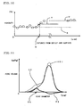
- a diagram shown on the left side is a schematic diagram showing the section of the honeycomb structure obtained by the manufacturing method of the present invention, the section being parallel to the thickness direction of "the upstream layer 2 of the partition wall” and “the downstream layer 11 of the partition wall”
- a graph shown on the right side is a graph schematically showing the deposited amount (the existing amount) of the particulate matters in positions of "the upstream layer 2 of the partition wall” and "the downstream layer 11 of the partition wall” in the thickness direction.
- the x-axis indicates the deposited amount of the particulate matters
- the y-axis indicates the positions in the thickness direction (the position).
- the particulate matters are entirely collected (present) in the thickness direction of "the upstream layer 2 of the partition wall". Therefore, in the whole "upstream layer 2 of the partition wall", the particulate matters come in contact with the particulate matter oxidation catalyst, and the particulate matters can efficiently be subjected to an oxidation treatment.
- a plurality of honeycomb structures are prepared by the method of the present invention, the resultant plurality of honeycomb structures (honeycomb segments 21) are joined by using a joining material 22, and the outer peripheral surface of the honeycomb structures may be cut and processed into a desired shape to prepare a honeycomb structure of a joined type (the joined type honeycomb structure) 50 as shown in Fig. 8 .
- Each honeycomb segment preferably has a quadrangular post-like shape.
- the outer peripheral surface of each honeycomb segment is coated with the joining material, and the honeycomb segments are assembled with one another and pressed, preferably followed by heating and drying.
- a joined honeycomb segment article obtained by joining the honeycomb segments together entirely has the quadrangular post-like shape.
- Fig. 8 is a perspective view schematically showing the joined type honeycomb structure obtained by joining the honeycomb structures manufactured by the manufacturing method of the present invention.
- the joining material 22 include a material constituted of an inorganic fiber, an inorganic binder, an organic binder and inorganic particles.
- the inorganic fiber include oxide fibers of aluminosilicate, magnesium silicate, alumina and the like, and another fiber (e.g., a SiC fiber).
- the inorganic binder include a silica sol, an alumina sol and clay.
- the organic binder include polyvinyl alcohol, carboxymethyl cellulose and methyl cellulose.
- the inorganic particles include particles of ceramic materials such as silicon carbide, silicon nitride, cordierite, alumina and mullite.
- the coating material 23 include the material constituted of the inorganic fiber, the inorganic binder, the organic binder and the inorganic particles.
- the same material as the joining material 22 may be used, or coating properties may be taken into consideration to regulate the composition and water ratio of the material.
- a raw material mixed powder containing 80 mass% of SiC powder and 20 mass% of metallic Si powder was used, and hydroxypropoxyl methyl cellulose as an organic binder, starch and acrylic acid based polymer resin as pore formers, further a surfactant and water were added to the raw material, to prepare a puddle having plasticity.
- the resultant puddle was subjected to extrusion forming by an extrusion forming machine, and dried with microwaves and hot air, to obtain a formed honeycomb article having partition wall thicknesses of 450 ⁇ m, a cell density of about 31 cells/cm 2 (200 cells/square inch), a square section with one side of 35 mm and a length of 178 mm.
- the particle diameters of the respective materials and the amounts of the materials to be added were regulated so that the porosities and average pore diameter of the resultant upstream layers of partition walls were values described later.
- An organic binder, a pore former, a surfactant and water were added to mixed powder containing 80 mass% of SiC powder and 20 mass% of metallic Si powder to prepare a downstream layer forming slurry.
- the particle diameters of the respective materials and the amounts of the materials to be added were regulated so that the porosities and average pore diameter of the resultant downstream layers of the partition walls were values described later.
- the prepared downstream layer forming slurry was fed into predetermined cells from opening ends of the cells on one side, the downstream layer forming slurry was charged into the predetermined cells, and a surplus slurry was removed, thereby obtaining a state in which the inner wall surfaces of the predetermined cells were coated with the downstream layer forming slurry, followed by drying, to prepare a coated and dried honeycomb article. It is to be noted that the predetermined cells and the remaining cells were alternately arranged.
- Plugging portions were disposed in both cell end faces of the coated and dried honeycomb article so that the plugging portions and cell open frontal areas formed checkered patterns in the faces.
- the plugging portions were formed of the same material as that forming the formed honeycomb article.
- a method of forming the plugging portions was as follows. In one end face of the resultant coated and dried honeycomb article, the remaining cells (the opening ends of the remaining cells) were covered with a mask, the one end face was immersed into a storage container where a plugging material was received, and the plugging material was inserted into the predetermined cells which were not covered with any mask, to form the plugging portions.
- the predetermined cells (the opening ends of the predetermined cells), which were not covered with any mask in the one end face, were covered with the mask, the other end face was immersed into the storage container where the plugging material was received, and the plugging material was inserted into the remaining cells which were not covered with any mask, to form plugging portions 5.
- honeycomb structure a sintered article.
- the resultant honeycomb structure was a honeycomb structure in which porous downstream layers having an average pore diameter smaller than that of the partition walls were applied onto the inner wall surfaces of the predetermined cells and which had the formed plugging portions.
- SiC powder as inorganic particles, an aluminosilicate fiber as an oxide fiber, an aqueous silica sol solution as a colloidal oxide and clay were mixed, respectively, water was further added to the materials, and the materials were mixed by a mixer for 30 minutes, to obtain slurry for joining material layers. Then, the honeycomb segment outer peripheral wall of each of the resultant 16 honeycomb structures (honeycomb segments) was coated with the joining material layer slurry having a thickness of about 1 mm, to form the joining material layer, and another honeycomb segment was disposed on the layer. This step was repeated, and a laminated article constituted of 4x4 combination of 16 honeycomb segments was prepared.
- the laminated article was dried at 120°C for two hours, to obtain a joined honeycomb segment article in which the 16 honeycomb segments were bonded via the joining material layers.
- the article was coated with an outer periphery coating slurry, dried at 700°C for two hours, and hardened, to obtain a joined type honeycomb structure having a dimension of ⁇ 144 mm x 178 mm.
- the outer periphery coating slurry the same slurry as the slurry for the joining material layers was used.
- Fig. 9 is an SEM photograph of a section of each partition wall (the upstream layer of the partition wall and the downstream layer of the partition wall) of the joined type honeycomb structure of Example 1, the section being parallel to a thickness direction.
- the porosities, thicknesses and average pore diameters of the upstream layer of the partition wall (referred to simply as “the upstream layer” sometimes) and the downstream layer of the partition wall were measured. Results are shown in Table 1.
- pore diameters means “the average pore diameter”.
- the image of the section of each partition wall of the joined type honeycomb structure was taken by using an SEM.
- a position a region from the surface of the partition wall on an inlet side (an exhaust gas inflow side in the thickness direction of the partition wall) to the center of the partition wall) sufficiently away from the surface of the partition wall on an outlet side (an exhaust gas outflow side in the thickness direction of the partition wall)
- the space/solid area ratios of 20 square view fields one side of a square was 1/1000 of the thickness of the partition wall
- the image of the section of the partition wall of the joined type honeycomb structure was taken by using the SEM.
- the space/solid area ratios of 20 square view fields were measured, respectively, and the resultant space/solid area ratios were averaged for each region.
- the image of the section of the partition wall of the joined type honeycomb structure was taken by using the SEM, and the thickness was measured through the image.
- the image of the section of the partition wall of the joined type honeycomb structure was taken by using the SEM.
- a region (a region from the surface of the partition wall on the outlet side to the center of the partition wall) having a thickness of a half of a partition wall thickness was divided into 1000 regions in the thickness direction, and the porosity of the square in each divided region was measured as the space/solid area ratio of the image from the region near the surface of the partition wall on the outlet side, and the average value of 20 view fields was plotted for each distance with respect to the distance from the outlet-side surface ( Fig. 10 ).
- a thickness w of the downstream layer of the partition wall there was obtained the distance of a position where a straight line formed by an arithmetic average z ((x+y)/2) of a porosity x of the downstream layer and a porosity y of the upstream layer intersected with a line connecting the above porosity plots to each other, from the surface (i.e., the distance from the outlet-side surface, corresponding to the above arithmetic average porosity on the line connecting the above plots to each other).
- Fig. 10 is a graph showing a relation between the distance from the outlet-side surface of the partition wall (the distance in the thickness direction) and the porosity in the position of the distance.
- the partition wall was cut from the joined type honeycomb structure, the downstream layer of the partition wall was removed by grinding, the average pore diameter of the remaining portion of the partition wall was measured, and this diameter was obtained as the average pore diameter of the partition wall upstream layer.
- the average pore diameter was obtained by using a mercury porosimeter.
- the partition wall was cut from the joined type honeycomb structure, and the pore distribution of the partition wall was measured by using the mercury porosimeter. Afterward, the downstream layer of the partition wall was removed from the partition wall by the grinding, and the pore distribution of the remaining portion (corresponding to the upstream layer of the partition wall) was measured.
- a difference between a pore distribution 51 of the whole partition wall and the pore distribution (a pore distribution 52 of the upstream layer of the partition wall) of a portion (corresponding to the upstream layer of the partition wall) of the partition wall excluding the downstream layer of the partition wall was considered as a pore distribution 53 of the downstream layer of the partition wall, and a pore diameter forming a peak in the pore distribution was considered as an average pore diameter 54 of the downstream layer of the partition wall (see Fig. 11).
- FIG. 11 is a graph showing the pore distribution of the whole partition wall (the whole partition wall including the upstream layer of the partition wall and the downstream layer of the partition wall), the pore distribution of the upstream layer of the partition wall, the pore distribution of the downstream layer of the partition wall and the average pore diameter of the downstream layer of the partition wall.
- a catalyst was loaded in the resultant joined type honeycomb structure.
- a catalyst slurry was prepared by adding an Al 2 O 3 sol and a water content to a Pt-loaded ⁇ -Al 2 O 3 catalyst and CeO 2 powder (a co-catalyst).
- the catalyst slurry was loaded in the joined type honeycomb structure by wash coating so that a platinum component was 1.06 g/L with respect to the joined type honeycomb structure and the total component was 30 g/L.
- a catalyst loading method was a method of allowing the catalyst slurry to flow into the cells (the cells on an exhaust gas inflow side) from the end face of the joined type honeycomb structure on the exhaust gas inflow side.
- the catalyst-loaded joined type honeycomb structure was mounted in a 2.0-liter (L) diesel engine, and 8 g/liter (g/L) of particulate matters (PM) were deposited in the catalyst-loaded joined type honeycomb structure at a constant rate of 2000 rpm x 50 Nm.
- the catalyst-loaded joined type honeycomb structure was removed, and the mass of the particulate matters (PM) deposited in the catalyst-loaded joined type honeycomb structure was measured. After measuring the mass, the catalyst-loaded joined type honeycomb structure including the deposited particulate matters was attached again, an exhaust gas temperature was raised by post injection, and the inlet gas temperature of the catalyst-loaded joined type honeycomb structure was kept at 650°C for ten minutes.
- the post injection was stopped, the catalyst-loaded joined type honeycomb structure was removed, and the mass of the particulate matters (PM) deposited in the catalyst-loaded joined type honeycomb structure was measured.
- a ratio of the mass of the particulate matters burnt in the test with respect to the mass of the deposited particulate matters was obtained as a regeneration efficiency indicating the degree of the burning of the particulate matters (PM).
- a catalyst-loaded joined type honeycomb structure was prepared in the same manner as in Example 1 except that any partition wall downstream layer was not formed.
- An average pore diameter and porosity were measured by the following methods.
- a regeneration efficiency test, the measurement of soot loading pressure drop and the evaluation of PM emission were performed by the above methods. Results are shown in Table 1.
- the porosity was measured by using a mercury porosimeter (AutoPore III manufactured by Micromeritics Co.).
- the average pore diameter was measured by using the mercury porosimeter (AutoPore III manufactured by Micromeritics Co.).
- a honeycomb structure was prepared in the same manner as in Example 1 except that after forming plugging portions in a formed honeycomb article and firing the article, downstream layers were formed and the article was fired again. Since the firing was performed twice in the manufacturing method of the honeycomb structure of Comparative Example 2, production efficiency lowered as much as about 25%. It is to be noted that the production efficiency is calculated based on a manufacturing cost.
- a downstream layer having a thickness of 40 ⁇ m, a porosity of 40% and an average pore diameter of 5 ⁇ m was formed on the face of the partition wall on the exhaust gas outflow side (the outflow side of the partition wall in a thickness direction when the exhaust gas passed through the partition wall). Moreover, it has been seen from Fig. 9 that the downstream layer 42 did not penetrate the pores of the upstream layer 41 but was formed in a layered state on the surface of the upstream layer 41.
- Example 1 and Comparative Example 1 had a regeneration efficiency of about 55%, and a large difference was not recognized between both the examples. This is supposedly because both the catalyst-loaded joined type honeycomb structures of Example 1 and Comparative Example 1 have large partition wall pore diameters, the catalyst is loaded in the pores, hence a contact efficiency between the catalyst and collected particulate matters improves, and a burning speed can be increased.
- Example 1 It is considered that a reason why any excessive pressure drop rise was not recognized in this manner even in the catalyst-loaded joined type honeycomb structure of Example 1 is that the agglomerated particulate matters were deposited in a bridged state on an interface between the upstream layer and the downstream layer and that the penetration of the particulate matters through the downstream layer (through the pores) was suppressed. Therefore, the particulate matters were not easily deposited in the pores of the downstream layer, and the pressure drop rise was suppressed.
- the manufacturing method of the present invention can efficiently manufacture a honeycomb structure which can preferably be used for collecting or removing particulates included in exhaust gases discharged from an internal combustion engine typified by a diesel engine, an engine for an ordinary car or an engine for a large vehicle such as a truck or a bus, and various types of burning devices.
- an internal combustion engine typified by a diesel engine, an engine for an ordinary car or an engine for a large vehicle such as a truck or a bus, and various types of burning devices.
Claims (5)
- Procédé de fabrication d'une structure en nid d'abeilles, comprenant les étapes :de formation d'un matériau de formation contenant une céramique en un élément en nid d'abeilles comprenant des parois de séparation poreuses qui séparent et forment une pluralité de cellules agissant en tant que canaux traversants d'un fluide ;de séchage de l'élément en nid d'abeilles formé pour préparer un élément en nid d'abeilles séché ;de formation de parties d'obturation dans les extrémités d'ouverture des cellules prédéterminées d'un côté et dans les extrémités d'ouverture des cellules restantes de l'autre côté dans l'élément en nid d'abeilles séché ;de chargement d'une boue de formation de couche en aval contenant une céramique dans les cellules prédéterminées de l'élément en nid d'abeilles séché comportant les parties d'obturation formées, de déchargement de la boue de formation de couche en aval pour recouvrir les surfaces de parois intérieures des cellules prédéterminées avec la boue de formation de couche en aval, et de séchage ensuite de l'élément pour préparer l'élément en nid d'abeilles revêtu et séché dans lequel des films de formation de couche en aval sont appliqués sur les surfaces de parois intérieures des cellules prédéterminées ; etde cuisson de l'élément en nid d'abeilles revêtu et séché comportant les parties d'obturation formées pour préparer la structure en nid d'abeilles dans laquelle les couches poreuses en aval ayant un diamètre de pore moyen inférieur à celui des parois de séparation sont appliquées sur les surfaces de parois intérieures des cellules prédéterminées et qui comporte les parties d'obturation formées.
- Procédé de fabrication de la structure en nid d'abeilles selon la revendication 1, dans lequel la céramique contenue dans le matériau de formation de l'élément en nid d'abeilles formé est identique à celle contenue dans la boue de formation de couche en aval.
- Procédé de fabrication de la structure en nid d'abeilles selon la revendication 2, dans lequel la céramique contient des particules de carbure de silicium et du silicium métallique.
- Procédé de fabrication de la structure en nid d'abeilles selon l'une quelconque des revendications 1 à 3, dans lequel l'élément en nid d'abeilles revêtu et séché comportant les parties d'obturation formées est cuit dans une plage de température de 1400 à 1800 °C.
- Procédé de fabrication de la structure en nid d'abeilles selon l'une quelconque des revendications 1 à 4, dans lequel les couches en aval ont un diamètre de pore moyen de 1 à 15 µm et les parois de séparation ont un diamètre de pore moyen de 35 à 80 µm dans la structure en nid d'abeilles comportant les parties d'obturation formées.
Applications Claiming Priority (1)
| Application Number | Priority Date | Filing Date | Title |
|---|---|---|---|
| JP2008103256A JP5031647B2 (ja) | 2008-04-11 | 2008-04-11 | ハニカム構造体の製造方法 |
Publications (3)
| Publication Number | Publication Date |
|---|---|
| EP2108494A2 EP2108494A2 (fr) | 2009-10-14 |
| EP2108494A3 EP2108494A3 (fr) | 2011-06-01 |
| EP2108494B1 true EP2108494B1 (fr) | 2014-07-02 |
Family
ID=40823191
Family Applications (1)
| Application Number | Title | Priority Date | Filing Date |
|---|---|---|---|
| EP09251057.7A Active EP2108494B1 (fr) | 2008-04-11 | 2009-04-08 | Procédé de fabrication de structure en nid d'abeille |
Country Status (2)
| Country | Link |
|---|---|
| EP (1) | EP2108494B1 (fr) |
| JP (1) | JP5031647B2 (fr) |
Families Citing this family (9)
| Publication number | Priority date | Publication date | Assignee | Title |
|---|---|---|---|---|
| EP2556871B1 (fr) | 2010-03-31 | 2016-09-07 | NGK Insulators, Ltd. | Filtre en nid d'abeilles |
| JP5533190B2 (ja) * | 2010-04-22 | 2014-06-25 | いすゞ自動車株式会社 | パティキュレートフィルター及びその再生方法 |
| CN103080047A (zh) | 2010-08-31 | 2013-05-01 | 康宁股份有限公司 | 具有涂覆通道的多孔陶瓷制品及其制造方法 |
| JP5405538B2 (ja) | 2010-09-01 | 2014-02-05 | 日本碍子株式会社 | ハニカム構造体 |
| BR112013010788A2 (pt) * | 2010-11-02 | 2016-08-09 | Haldor Topsoe As | método para a preparação de um filtro em partículas catalisado e filtro em partículas catalisado |
| JP5604346B2 (ja) | 2011-03-23 | 2014-10-08 | 日本碍子株式会社 | ハニカムフィルタ |
| JP5632318B2 (ja) * | 2011-03-24 | 2014-11-26 | 日本碍子株式会社 | ハニカムフィルタ及びその製造方法 |
| US10633297B2 (en) * | 2018-03-16 | 2020-04-28 | Ngk Insulators, Ltd. | Method of manufacturing honeycomb structure |
| US11266982B2 (en) * | 2018-03-30 | 2022-03-08 | Mitsui Mining & Smelting Co., Ltd. | Exhaust gas purification catalyst |
Family Cites Families (7)
| Publication number | Priority date | Publication date | Assignee | Title |
|---|---|---|---|---|
| FR2502508B1 (fr) * | 1981-03-30 | 1985-10-25 | Geceral Grpt Etu Ceramiques Al | Structure de filtration, procede de realisation de telles structures et dispositif d'ultrafiltration en comportant |
| JP3874443B2 (ja) * | 1996-04-12 | 2007-01-31 | 株式会社日本自動車部品総合研究所 | パティキュレート捕集用フィルタ |
| ATE236700T1 (de) * | 1998-07-07 | 2003-04-15 | Corning Inc | Dieselabgasfilter |
| JP2002309921A (ja) * | 2001-04-16 | 2002-10-23 | Denso Corp | 排気浄化装置及びその製造方法 |
| JP4355506B2 (ja) * | 2003-03-28 | 2009-11-04 | 日本碍子株式会社 | 触媒担持フィルタ及びこれを用いた排ガス浄化システム |
| JP2005118657A (ja) * | 2003-10-15 | 2005-05-12 | Toshiba Ceramics Co Ltd | セラミックスフィルターとその製造方法 |
| JP2006077672A (ja) * | 2004-09-09 | 2006-03-23 | Toyota Motor Corp | 排ガス浄化フィルタ及び排ガス浄化装置 |
-
2008
- 2008-04-11 JP JP2008103256A patent/JP5031647B2/ja active Active
-
2009
- 2009-04-08 EP EP09251057.7A patent/EP2108494B1/fr active Active
Also Published As
| Publication number | Publication date |
|---|---|
| JP5031647B2 (ja) | 2012-09-19 |
| EP2108494A2 (fr) | 2009-10-14 |
| EP2108494A3 (fr) | 2011-06-01 |
| JP2009248070A (ja) | 2009-10-29 |
Similar Documents
| Publication | Publication Date | Title |
|---|---|---|
| EP2108494B1 (fr) | Procédé de fabrication de structure en nid d'abeille | |
| EP2105200B1 (fr) | Filtre revêtu avec un catalyseur | |
| US9175587B2 (en) | Substrate with surface-collection-layer and catalyst-carrying substrate with surface-collection-layer | |
| EP2364765B1 (fr) | Corps de catalyseur en nid d'abeille | |
| EP1403231B1 (fr) | Procede de production d'un corps ceramique fritté poreux | |
| EP2174701B1 (fr) | Filtre en nids d'abeilles | |
| EP2103342B1 (fr) | Filtre revêtu avec un catalyseur | |
| JP5726414B2 (ja) | 触媒担持フィルタ、及び排ガス浄化システム | |
| EP2737945B1 (fr) | Corps de catalyseur en nid d'abeille | |
| EP2042224B1 (fr) | Filtre en nids d'abeilles | |
| EP2380649B1 (fr) | Dispositif de purification des gaz d'échappement | |
| EP2364764B1 (fr) | Dispositif de purification de gaz d'échappement et procédé de purification de gaz d'échappement | |
| US20090247399A1 (en) | Catalytic diesel particulate filter and manufacturing method thereof | |
| EP2380650A1 (fr) | Corps de catalyseur en nid d'abeille | |
| EP2177253B1 (fr) | Structure en nid d'abeille | |
| EP2105199A1 (fr) | Filtre revêtu avec un catalyseur | |
| EP2108448B1 (fr) | Corps de catalyseur en nid d'abeille | |
| JP2022115873A (ja) | 触媒塗工ガソリンパティキュレートフィルター及びその製造方法 | |
| EP2371441B1 (fr) | Dispositif de purification des gaz d'échappement | |
| JP5714568B2 (ja) | ハニカムフィルタ | |
| JP7289813B2 (ja) | セラミックス多孔体及びその製造方法、並びに集塵用フィルタ | |
| US20200386134A1 (en) | Filter and method for manufacturing same | |
| EP2609980A1 (fr) | Filtre en nids dýabeilles |
Legal Events
| Date | Code | Title | Description |
|---|---|---|---|
| PUAI | Public reference made under article 153(3) epc to a published international application that has entered the european phase |
Free format text: ORIGINAL CODE: 0009012 |
|
| AK | Designated contracting states |
Kind code of ref document: A2 Designated state(s): AT BE BG CH CY CZ DE DK EE ES FI FR GB GR HR HU IE IS IT LI LT LU LV MC MK MT NL NO PL PT RO SE SI SK TR |
|
| PUAL | Search report despatched |
Free format text: ORIGINAL CODE: 0009013 |
|
| AK | Designated contracting states |
Kind code of ref document: A3 Designated state(s): AT BE BG CH CY CZ DE DK EE ES FI FR GB GR HR HU IE IS IT LI LT LU LV MC MK MT NL NO PL PT RO SE SI SK TR |
|
| AX | Request for extension of the european patent |
Extension state: AL BA RS |
|
| 17P | Request for examination filed |
Effective date: 20110801 |
|
| 17Q | First examination report despatched |
Effective date: 20111118 |
|
| RIC1 | Information provided on ipc code assigned before grant |
Ipc: B01J 23/63 20060101ALI20131017BHEP Ipc: C04B 41/00 20060101ALI20131017BHEP Ipc: C04B 41/45 20060101ALI20131017BHEP Ipc: C04B 41/87 20060101ALI20131017BHEP Ipc: B01J 37/02 20060101ALI20131017BHEP Ipc: B01J 35/04 20060101ALI20131017BHEP Ipc: B28B 11/00 20060101AFI20131017BHEP Ipc: B28B 11/04 20060101ALI20131017BHEP |
|
| GRAP | Despatch of communication of intention to grant a patent |
Free format text: ORIGINAL CODE: EPIDOSNIGR1 |
|
| INTG | Intention to grant announced |
Effective date: 20140115 |
|
| GRAS | Grant fee paid |
Free format text: ORIGINAL CODE: EPIDOSNIGR3 |
|
| GRAA | (expected) grant |
Free format text: ORIGINAL CODE: 0009210 |
|
| AK | Designated contracting states |
Kind code of ref document: B1 Designated state(s): AT BE BG CH CY CZ DE DK EE ES FI FR GB GR HR HU IE IS IT LI LT LU LV MC MK MT NL NO PL PT RO SE SI SK TR |
|
| REG | Reference to a national code |
Ref country code: GB Ref legal event code: FG4D |
|
| REG | Reference to a national code |
Ref country code: CH Ref legal event code: EP Ref country code: AT Ref legal event code: REF Ref document number: 675667 Country of ref document: AT Kind code of ref document: T Effective date: 20140715 |
|
| REG | Reference to a national code |
Ref country code: IE Ref legal event code: FG4D |
|
| REG | Reference to a national code |
Ref country code: DE Ref legal event code: R096 Ref document number: 602009025056 Country of ref document: DE Effective date: 20140814 |
|
| REG | Reference to a national code |
Ref country code: AT Ref legal event code: MK05 Ref document number: 675667 Country of ref document: AT Kind code of ref document: T Effective date: 20140702 |
|
| REG | Reference to a national code |
Ref country code: NL Ref legal event code: VDEP Effective date: 20140702 |
|
| REG | Reference to a national code |
Ref country code: LT Ref legal event code: MG4D |
|
| PG25 | Lapsed in a contracting state [announced via postgrant information from national office to epo] |
Ref country code: FI Free format text: LAPSE BECAUSE OF FAILURE TO SUBMIT A TRANSLATION OF THE DESCRIPTION OR TO PAY THE FEE WITHIN THE PRESCRIBED TIME-LIMIT Effective date: 20140702 Ref country code: NO Free format text: LAPSE BECAUSE OF FAILURE TO SUBMIT A TRANSLATION OF THE DESCRIPTION OR TO PAY THE FEE WITHIN THE PRESCRIBED TIME-LIMIT Effective date: 20141002 Ref country code: PT Free format text: LAPSE BECAUSE OF FAILURE TO SUBMIT A TRANSLATION OF THE DESCRIPTION OR TO PAY THE FEE WITHIN THE PRESCRIBED TIME-LIMIT Effective date: 20141103 Ref country code: BG Free format text: LAPSE BECAUSE OF FAILURE TO SUBMIT A TRANSLATION OF THE DESCRIPTION OR TO PAY THE FEE WITHIN THE PRESCRIBED TIME-LIMIT Effective date: 20141002 Ref country code: ES Free format text: LAPSE BECAUSE OF FAILURE TO SUBMIT A TRANSLATION OF THE DESCRIPTION OR TO PAY THE FEE WITHIN THE PRESCRIBED TIME-LIMIT Effective date: 20140702 Ref country code: SE Free format text: LAPSE BECAUSE OF FAILURE TO SUBMIT A TRANSLATION OF THE DESCRIPTION OR TO PAY THE FEE WITHIN THE PRESCRIBED TIME-LIMIT Effective date: 20140702 Ref country code: GR Free format text: LAPSE BECAUSE OF FAILURE TO SUBMIT A TRANSLATION OF THE DESCRIPTION OR TO PAY THE FEE WITHIN THE PRESCRIBED TIME-LIMIT Effective date: 20141003 Ref country code: LT Free format text: LAPSE BECAUSE OF FAILURE TO SUBMIT A TRANSLATION OF THE DESCRIPTION OR TO PAY THE FEE WITHIN THE PRESCRIBED TIME-LIMIT Effective date: 20140702 Ref country code: CZ Free format text: LAPSE BECAUSE OF FAILURE TO SUBMIT A TRANSLATION OF THE DESCRIPTION OR TO PAY THE FEE WITHIN THE PRESCRIBED TIME-LIMIT Effective date: 20140702 |
|
| PG25 | Lapsed in a contracting state [announced via postgrant information from national office to epo] |
Ref country code: LV Free format text: LAPSE BECAUSE OF FAILURE TO SUBMIT A TRANSLATION OF THE DESCRIPTION OR TO PAY THE FEE WITHIN THE PRESCRIBED TIME-LIMIT Effective date: 20140702 Ref country code: CY Free format text: LAPSE BECAUSE OF FAILURE TO SUBMIT A TRANSLATION OF THE DESCRIPTION OR TO PAY THE FEE WITHIN THE PRESCRIBED TIME-LIMIT Effective date: 20140702 Ref country code: NL Free format text: LAPSE BECAUSE OF FAILURE TO SUBMIT A TRANSLATION OF THE DESCRIPTION OR TO PAY THE FEE WITHIN THE PRESCRIBED TIME-LIMIT Effective date: 20140702 Ref country code: HR Free format text: LAPSE BECAUSE OF FAILURE TO SUBMIT A TRANSLATION OF THE DESCRIPTION OR TO PAY THE FEE WITHIN THE PRESCRIBED TIME-LIMIT Effective date: 20140702 Ref country code: PL Free format text: LAPSE BECAUSE OF FAILURE TO SUBMIT A TRANSLATION OF THE DESCRIPTION OR TO PAY THE FEE WITHIN THE PRESCRIBED TIME-LIMIT Effective date: 20140702 Ref country code: AT Free format text: LAPSE BECAUSE OF FAILURE TO SUBMIT A TRANSLATION OF THE DESCRIPTION OR TO PAY THE FEE WITHIN THE PRESCRIBED TIME-LIMIT Effective date: 20140702 Ref country code: IS Free format text: LAPSE BECAUSE OF FAILURE TO SUBMIT A TRANSLATION OF THE DESCRIPTION OR TO PAY THE FEE WITHIN THE PRESCRIBED TIME-LIMIT Effective date: 20141102 |
|
| REG | Reference to a national code |
Ref country code: DE Ref legal event code: R097 Ref document number: 602009025056 Country of ref document: DE |
|
| PG25 | Lapsed in a contracting state [announced via postgrant information from national office to epo] |
Ref country code: RO Free format text: LAPSE BECAUSE OF FAILURE TO SUBMIT A TRANSLATION OF THE DESCRIPTION OR TO PAY THE FEE WITHIN THE PRESCRIBED TIME-LIMIT Effective date: 20140702 Ref country code: IT Free format text: LAPSE BECAUSE OF FAILURE TO SUBMIT A TRANSLATION OF THE DESCRIPTION OR TO PAY THE FEE WITHIN THE PRESCRIBED TIME-LIMIT Effective date: 20140702 Ref country code: EE Free format text: LAPSE BECAUSE OF FAILURE TO SUBMIT A TRANSLATION OF THE DESCRIPTION OR TO PAY THE FEE WITHIN THE PRESCRIBED TIME-LIMIT Effective date: 20140702 Ref country code: SK Free format text: LAPSE BECAUSE OF FAILURE TO SUBMIT A TRANSLATION OF THE DESCRIPTION OR TO PAY THE FEE WITHIN THE PRESCRIBED TIME-LIMIT Effective date: 20140702 Ref country code: DK Free format text: LAPSE BECAUSE OF FAILURE TO SUBMIT A TRANSLATION OF THE DESCRIPTION OR TO PAY THE FEE WITHIN THE PRESCRIBED TIME-LIMIT Effective date: 20140702 |
|
| PLBE | No opposition filed within time limit |
Free format text: ORIGINAL CODE: 0009261 |
|
| STAA | Information on the status of an ep patent application or granted ep patent |
Free format text: STATUS: NO OPPOSITION FILED WITHIN TIME LIMIT |
|
| 26N | No opposition filed |
Effective date: 20150407 |
|
| PG25 | Lapsed in a contracting state [announced via postgrant information from national office to epo] |
Ref country code: SI Free format text: LAPSE BECAUSE OF FAILURE TO SUBMIT A TRANSLATION OF THE DESCRIPTION OR TO PAY THE FEE WITHIN THE PRESCRIBED TIME-LIMIT Effective date: 20140702 Ref country code: LU Free format text: LAPSE BECAUSE OF FAILURE TO SUBMIT A TRANSLATION OF THE DESCRIPTION OR TO PAY THE FEE WITHIN THE PRESCRIBED TIME-LIMIT Effective date: 20150408 Ref country code: MC Free format text: LAPSE BECAUSE OF FAILURE TO SUBMIT A TRANSLATION OF THE DESCRIPTION OR TO PAY THE FEE WITHIN THE PRESCRIBED TIME-LIMIT Effective date: 20140702 |
|
| REG | Reference to a national code |
Ref country code: CH Ref legal event code: PL |
|
| GBPC | Gb: european patent ceased through non-payment of renewal fee |
Effective date: 20150408 |
|
| REG | Reference to a national code |
Ref country code: IE Ref legal event code: MM4A |
|
| PG25 | Lapsed in a contracting state [announced via postgrant information from national office to epo] |
Ref country code: CH Free format text: LAPSE BECAUSE OF NON-PAYMENT OF DUE FEES Effective date: 20150430 Ref country code: GB Free format text: LAPSE BECAUSE OF NON-PAYMENT OF DUE FEES Effective date: 20150408 Ref country code: LI Free format text: LAPSE BECAUSE OF NON-PAYMENT OF DUE FEES Effective date: 20150430 |
|
| REG | Reference to a national code |
Ref country code: FR Ref legal event code: PLFP Year of fee payment: 8 |
|
| PG25 | Lapsed in a contracting state [announced via postgrant information from national office to epo] |
Ref country code: IE Free format text: LAPSE BECAUSE OF NON-PAYMENT OF DUE FEES Effective date: 20150408 |
|
| PG25 | Lapsed in a contracting state [announced via postgrant information from national office to epo] |
Ref country code: BE Free format text: LAPSE BECAUSE OF FAILURE TO SUBMIT A TRANSLATION OF THE DESCRIPTION OR TO PAY THE FEE WITHIN THE PRESCRIBED TIME-LIMIT Effective date: 20140702 |
|
| PG25 | Lapsed in a contracting state [announced via postgrant information from national office to epo] |
Ref country code: MT Free format text: LAPSE BECAUSE OF FAILURE TO SUBMIT A TRANSLATION OF THE DESCRIPTION OR TO PAY THE FEE WITHIN THE PRESCRIBED TIME-LIMIT Effective date: 20140702 |
|
| REG | Reference to a national code |
Ref country code: FR Ref legal event code: PLFP Year of fee payment: 9 |
|
| PG25 | Lapsed in a contracting state [announced via postgrant information from national office to epo] |
Ref country code: HU Free format text: LAPSE BECAUSE OF FAILURE TO SUBMIT A TRANSLATION OF THE DESCRIPTION OR TO PAY THE FEE WITHIN THE PRESCRIBED TIME-LIMIT; INVALID AB INITIO Effective date: 20090408 |
|
| PG25 | Lapsed in a contracting state [announced via postgrant information from national office to epo] |
Ref country code: TR Free format text: LAPSE BECAUSE OF FAILURE TO SUBMIT A TRANSLATION OF THE DESCRIPTION OR TO PAY THE FEE WITHIN THE PRESCRIBED TIME-LIMIT Effective date: 20140702 |
|
| REG | Reference to a national code |
Ref country code: FR Ref legal event code: PLFP Year of fee payment: 10 |
|
| PG25 | Lapsed in a contracting state [announced via postgrant information from national office to epo] |
Ref country code: MK Free format text: LAPSE BECAUSE OF FAILURE TO SUBMIT A TRANSLATION OF THE DESCRIPTION OR TO PAY THE FEE WITHIN THE PRESCRIBED TIME-LIMIT Effective date: 20140702 |
|
| PGFP | Annual fee paid to national office [announced via postgrant information from national office to epo] |
Ref country code: FR Payment date: 20200312 Year of fee payment: 12 |
|
| PG25 | Lapsed in a contracting state [announced via postgrant information from national office to epo] |
Ref country code: FR Free format text: LAPSE BECAUSE OF NON-PAYMENT OF DUE FEES Effective date: 20210430 |
|
| PGFP | Annual fee paid to national office [announced via postgrant information from national office to epo] |
Ref country code: DE Payment date: 20230228 Year of fee payment: 15 |