EP1825199B1 - Heizlüfter - Google Patents
Heizlüfter Download PDFInfo
- Publication number
- EP1825199B1 EP1825199B1 EP05808492A EP05808492A EP1825199B1 EP 1825199 B1 EP1825199 B1 EP 1825199B1 EP 05808492 A EP05808492 A EP 05808492A EP 05808492 A EP05808492 A EP 05808492A EP 1825199 B1 EP1825199 B1 EP 1825199B1
- Authority
- EP
- European Patent Office
- Prior art keywords
- housing
- fan heater
- elements
- heater according
- frame
- Prior art date
- Legal status (The legal status is an assumption and is not a legal conclusion. Google has not performed a legal analysis and makes no representation as to the accuracy of the status listed.)
- Expired - Lifetime
Links
Images


Classifications
-
- F—MECHANICAL ENGINEERING; LIGHTING; HEATING; WEAPONS; BLASTING
- F24—HEATING; RANGES; VENTILATING
- F24H—FLUID HEATERS, e.g. WATER OR AIR HEATERS, HAVING HEAT-GENERATING MEANS, e.g. HEAT PUMPS, IN GENERAL
- F24H9/00—Details
- F24H9/02—Casings; Cover lids; Ornamental panels
-
- F—MECHANICAL ENGINEERING; LIGHTING; HEATING; WEAPONS; BLASTING
- F24—HEATING; RANGES; VENTILATING
- F24H—FLUID HEATERS, e.g. WATER OR AIR HEATERS, HAVING HEAT-GENERATING MEANS, e.g. HEAT PUMPS, IN GENERAL
- F24H3/00—Air heaters
- F24H3/02—Air heaters with forced circulation
- F24H3/04—Air heaters with forced circulation the air being in direct contact with the heating medium, e.g. electric heating element
- F24H3/0405—Air heaters with forced circulation the air being in direct contact with the heating medium, e.g. electric heating element using electric energy supply, e.g. the heating medium being a resistive element; Heating by direct contact, i.e. with resistive elements, electrodes and fins being bonded together without additional element in-between
Definitions
- the invention relates to a fan heater according to the preamble of claim 1 and a modular system according to claim 24.
- heating fans which have a jammed in the housing PTC (positive temperature coefficient) element as a heating element.
- PTC elements operate self-regulating and temperature-limiting, so that overheating in the control cabinet or distribution box can be reliably avoided.
- a commercial electric fan heater in which in a housing the air to be heated is passed through a fan via an electrical resistance and pushed to the outside.
- a drive motor arranged in the interior of the housing is freely suspended and spring-mounted on the inner wall of the housing together with the resistor which is fastened to the motor. This is the motor, together with fan blades and the resistor, connected via tension springs to the housing.
- the radially aligned with respect to the engine springs are - uniformly spaced - fixed at one end to the inner housing wall of the housing and are attached with the other end to the outer wall of the motor.
- the invention is therefore based on the object to show a heater of the type mentioned in such a way that it is easy to manufacture and resistant.
- a heating fan which comprises a housing through which a longitudinal flow of air, a fan for conveying the air and at least one resiliently mounted on the housing by means of a holder heating element.
- the heating element is designed as a PTC element and the fan is mounted separately from the PTC element on the housing.
- kits comprising a heater just described, wherein at least two, each at least one fastening element for fixing the fan heater at a designated location having adapter plates and means for attaching either one of the adapter plates are provided on a housing of the fan heater ,
- An essential point of the invention is that the fan heater due to the PTC element and due to the separated storage of the element by the fan has a very simple design and operation.
- the handling of the fan heater is facilitated by the special physical properties of the PTC element.
- a PTC element is particularly well suited. Due to the invention Storage are now any shocks and / or vibrations. Not directly transferable to the PTC element, because the storage on the one hand allows a relative movement between the housing and the heating element.
- the shock / vibration protection is ensured with the invention, explicitly turning off the heater storage to a large extent, because the PTC element is mounted within the holder for themselves and thus undesirable interactions between the heating element and other components, such as the fan, especially at improper use of the fan heater, are avoidable.
- fan heater With the attached to a designated location in different ways fan heater, as it is provided with the modular principle, in addition, a secure mounting of the fan depending on different environmental conditions is possible. As a result, an additional protection of the heating element mounted in the fan heater can be achieved.
- the present invention also relates in particular to the mounting of a PTC element which is formed from filigree ceramic rods, so that the PTC element ultimately has a grid-shaped structure or is provided as a honeycomb body.
- the PTC element thus has a low flow resistance and can thus be traversed by sufficient air.
- the holder comprises at least one receiving element substantially fixedly connected or connectable to the heating element, which is spring-mounted relative to the housing.
- the receiving element ensures at the same time freedom of movement a secure hold of the heating element at a designated location in the heater.
- the so configured storage of the heating element can thus counteract the forces acting from the outside.
- the receiving element comprises a frame with claws, which are designed such that the heating element can be latched into the claws and thus firmly connected to the frame.
- the claws are elastically bendable for insertion of the heating element and resume the original shape when the heating element is placed.
- the trained with the claws Frame is used to connect the claws with each other and is preferably formed integrally with these.
- the frame can thus be produced in a simple and cost-effective manner.
- the frame extends along walls of the housing, so that the heating element can be designed as large as possible within the housing. Accordingly, the frame consists of four frame pages.
- the claws are formed as separate elements, so that they can be attached to the frame, for example.
- different claw sizes for different load cases and embodiments of the heating elements can be used.
- the receiving element has lower claw elements and upper claw elements, wherein the lower claw elements are formed directly on the frame and the upper claw elements are formed by at least one arranged on the frame spacer spaced from the frame.
- the upper and lower claw elements ensure a secure hold of the heating element within the receiving element and in particular prevent a longitudinal displacement of the heating element within the housing, d. H. in the longitudinal direction of the air permeable housing.
- the location of the lower and upper claw elements is defined with respect to the longitudinal direction of the housing, wherein the longitudinal direction of the housing corresponds to an air flow direction through the heater.
- claws or claw elements can be placed on the frame as separate elements, different heating element thicknesses can be accommodated in the receiving element with the aid of spacers of different length, aligned in the longitudinal direction of the housing. Once mounted in the housing frame is thus suitable for various heating elements.
- the lower claw elements and the upper claw elements are each arranged alternately on the frame.
- two lower claw elements and an intermediate upper claw element are provided per frame side. This can be achieved in a simple manner a stable hold of the heating element.
- the claws are arranged on the frame, that in each case a lower claw element and an upper claw element are opposed. This ensures a particularly secure hold of the heating element in the holder, in particular, if several, opposite claw elements are provided for each frame side.
- the claws are preferably only in the extension direction of the heating element, d. H. aligned perpendicular to the spacer elements bearing surfaces or contact surfaces, wherein the heating element then rests on the lower claw elements and is supported against the upper claw elements.
- the formation of the so-oriented support or contact surfaces facilitates the insertion of the heating element in the holder, wherein a sufficiently good grip of the heating element is ensured in the holder.
- a particularly secure reception can be achieved in that, instead of individual claw elements, a continuous lower bearing surface is formed on the frame. The heating element is then on a bottom completely on the support surface.
- a solution according to the invention provides that the frame has molded spring elements for resilient attachment to the housing.
- the receiving element is firmly connected to the housing and can still, as already mentioned above, move relative to the housing, so that the force acting on the receiving element and thus on the heating element forces can be met.
- the spring elements are formed integrally with the frame. This allows a very inexpensive and easy production of the holder.
- the spring elements are formed and attached to the frame such that they simultaneously act as lower claw elements, i. H. So serve as bearing surfaces for the heating element.
- spring elements are designed as separate elements which can be attached to the frame, different types of spring can be used depending on the load case and can also be exchanged.
- the spring elements may be attached to the frame either from above or else they are arranged below the frame.
- a preferred embodiment provides that the spring elements can be locked to holding devices of the housing.
- the housing z. B. recesses into which the spring elements can snap.
- the entire holder can be easily removed from the housing, so that the insertion of the heating element can be done for example outside the housing.
- the holder is then used together with the heating element in the housing. Also, in this way, the holder in a simple manner completely interchangeable.
- the frame is attached to only two opposite housing walls, wherein at least two spring elements are provided for the connection of the frame, each with a housing wall.
- the two spring elements per housing wall ensure sufficient support of the frame in or on the housing, while the attachment of the frame to only two opposite housing walls allows its sufficient freedom of movement.
- the spring elements are made of plastic.
- Plastic allows a stable design of resilient components with low mass. It is also conceivable to store the frame via coil springs made of metal.
- the holder comprises a plurality of separate receiving elements, which are each fastened to the heating element and having springs, for support on the housing. Also in this embodiment, the holder thus consists of the receiving elements and the corresponding springs.
- the holder can be completely attached to the heating element outside of the housing in this embodiment, so that the heating element is completely usable with the holder in a simple manner in the housing.
- a receiving element and a spring are provided in each case at a corner of the example square or rectangular-shaped disk-shaped heating element.
- the springs can intercept any transmitted through the housing shocks.
- a preferred embodiment provides that the springs are held against displacement in the longitudinal direction in the housing by at least one insertable into the housing intermediate piece. That is, the springs are mounted in or on the intermediate piece, so that the heating element is also resiliently mounted.
- the intermediate piece is in turn supported against the housing and / or against further Schulsupererbaumaschine.
- the heating element is mounted on the springs in a sandwich construction between two intermediate pieces, wherein both intermediate pieces are in turn supported against the housing and / or against further Schulmodalerbaumaschinemaschinemaschinener.
- the intermediate piece or the intermediate pieces advantageously have protruding elements for holding the springs, wherein the protruding elements are formed integrally with the intermediate piece and / or as attachable to the intermediate piece, separate elements.
- a trained with a spring-mounted heating fan heater can be formed when using two intermediate pieces, the one intermediate piece simultaneously as a touch guard, the other as an air guide unit.
- the visible from the outside contact protection grid for protection against interference with the heater then has on a lower side relative to the longitudinal direction of the housing, the protruding elements, for. B. pins, which press against the springs on an upper side of the heating element.
- the springs formed on an underside of the heating element then lie, for example, on an upper side of the air-guiding unit, relative to the longitudinal direction of the housing, or on receiving surfaces provided for this purpose, or are clamped by further pins formed on the air-guiding unit.
- the air guiding unit serves for adequate air guidance or air turbulence in the heating fan. This ensures that the air sucked in by a fan is expediently passed through the fan.
- the heating element has springs both on its underside and on its upper side.
- the springs z. B. formed as a disc elements, so that a portion of the discs extend over the top and another part of the discs on the underside of the heating element addition. That is, at a respective bearing point in each case only one spring is provided, which extends over both the top and on the bottom with respect to the longitudinal direction of the housing.
- the disk elements are accordingly z. B. attached via their respective centers on the heating element via the receiving elements.
- the air guide unit is designed to hold the fan against displacement in the longitudinal direction in the housing.
- the air guide unit for a stationary placement within the fan z. B. latched in the housing walls and has a resilient means for clamping the fan in the housing. Any, caused by the installation clearance of the fan in the housing can be compensated due to the resilient means on the air guide unit, so that the fan heater has no rattling components.
- the air guide unit is made of plastic, since plastic is an extremely stable and at the same time lightweight material. If the resilient device integrally formed on the air guide unit, so this is preferably formed of plastic.
- a provided as a separate element resilient device may, for. B. also be formed as at least one metallic coil spring or the like resilient element. Also, a plate spring or a plate spring package is suitable for the play-free mounting of the fan.
- a solution according to the invention provides that at least one housing wall of the fan heater housing has at least one fastening device for receiving an adapter plate on an outer side, wherein the adapter plate has at least one fastening element for fastening the fan heater at a location provided for this purpose.
- the fastening devices can, for. B. may be formed as a latching hook on the housing wall, via which the respective adapter plate can be suspended.
- the adapter plates are accordingly designed independently of their fastening elements such that any desired adapter plate can be fastened to the housing.
- the fasteners may, for. B. be provided as a clip-fastening means of an elastic and / or folding spring clip, wherein the heater then preferably on a rail, for. B. in a cabinet, can be fastened.
- the fastening elements can also have at least one elongate hole, so that the heating fan can be fastened to form a screw fastening at the location provided for this purpose.
- a solution according to the invention provides that the springs of the holder are made of plastic, z. B. of an elastomer, such as rubber or silicone. These materials allow sufficient resilience and are also lightweight and inexpensive.
- the receiving element or the receiving elements made of plastic.
- Plastics are extremely stable and break-resistant materials with low mass.
- receiving elements made of plastic can ensure a secure hold of the heating element and be easily stored resiliently.
- the housing of the fan heater is preferably made of plastic. This ensures stability and low mass of the fan heater.
- PTC heating elements are z. B. made of barium titanate as a base material with the addition of other metal oxides.
- the heating element in the heater according to the invention is preferably designed as a grid or honeycomb body and therefore has an extremely filigree structure.
- the grid structure allows a sufficiently high air flow through the heater with low flow resistance.
- the storage according to the invention is advantageous especially in the case of a heating element formed in this way, in particular in the case of improper handling of the heating fan, to avoid an impairment of the functionality of the heating element.
- the PTC heating element is characterized by an abrupt increase in resistance in a very limited temperature range.
- the PTC heating element is suitable as a self-regulating heating element, so that overheating, for. B. just inside the cabinet, is avoidable.
- the sensitive electronics can be precisely tempered in a simple manner.
- the fastening element is provided on the corresponding adapter plate as elastic and / or folding spring clip for forming a clip attachment and / or at least one slot for forming at least one screw with a desired placement point for the heater.
- a clip attachment that can be realized via the spring clip allows a quick change of location of the heater, while a screw connection ensures a particularly stable attachment.
- the Clipbefest Trent is in the case of an elastic strap, so a spring clip, preferably by jamming or deformation of a z. B. ⁇ -shaped portion of the bracket accomplished.
- the spring clip is preferably formed from a spring steel.
- a further preferred embodiment of the kit provides that the means for attaching either one of the adapter plates to the fan heater housing at least one latching hook on the housing of the fan heater and at least one recess and / or a projection or the like element on the adapter plates as a counterpart to the at least include a latching hook.
- the adapter plate with the desired fastener on the fan heater is attached as needed.
- Fig. 1 shows a heating fan 10 shown in perspective in a first preferred embodiment, wherein a holder 60 for supporting a heating element (not shown) is at least partially visible:
- the heater 10 has in this embodiment, a substantially cuboid, z. B. plastic-molded housing 11, wherein on a side wall of the housing 11, a terminal strip 16 for a power supply both for a housable in the housing 11 fan or a fan (not shown), as well as for, also in the housing 11th built-in heating element is provided.
- a cover of the bar 16 is formed for example of plastic.
- Another side wall has a fastening device 17 to the heater 10 at a designated location, for. B. in a cabinet to attach.
- the fastening device 17 is designed in this case such that, for example, an elastic metal strap (not shown) can be attached to the device 17 in order to enable a clip attachment at the desired location via this device.
- an elastic metal strap (not shown) can be attached to the device 17 in order to enable a clip attachment at the desired location via this device.
- a ⁇ -shaped area having bracket can be clamped by an elastic deformation at the appropriate place in the cabinet.
- an adapter plate (not shown) can also be mounted via the fastening device 17, this plate then having a corresponding fastening element around the fan at the designated location, z. B. to be mounted inside the cabinet. It is envisaged, as required, to be able to attach different fasteners on different plates on the housing of the fan heater. In this respect, the plates are designed so that they can be easily replaced.
- a closer version of the various fasteners follows in the following description.
- an upper contact protection grid 19 is provided to prevent the engagement from the outside in the fan 10. Through the contact protection grid 19 through the holder 60 is visible to the heating element.
- the top is defined with respect to the longitudinal direction L of the housing 11, the longitudinal direction L of the housing being an air flow direction Pe or Pa (cf. Fig. 8 ) through the fan heater 10 corresponds.
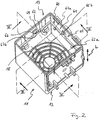
- FIG. 2 is an interior perspective view of the heater housing 11 according to the heater 10 of the first embodiment with the inventive holder 60, but shown without the upper guard. Only a lower contact protection grid 18 closes off the housing 11 on a lower side 12, relative to the longitudinal direction L of the housing 11, wherein the lower contact protection grid 18 is preferably formed integrally with the housing 11.
- the perspective view shows the holder 60 for holding the heating element (not shown), which comprises a receiving element 61 with a frame 64 and claws 65, wherein the claws 65 are formed such that the heating element can be latched into this and thus with the frame 64 and thus firmly connected to the receiving element 61.
- the claws 65 are preferably elastically bendable and enclose the heating element by resuming their original shape after insertion of the heating element.
- the heating element is securely fixed in the holder 60.
- the claws 65 are integrally connected by the frame 64.
- the frame 64 extends along housing walls of the housing 11, so that the heating element can be designed as large as possible within the housing 11.
- the frame 64 accordingly consists of four frame sides.
- the claws are formed as separate elements, so that they can be attached to the frame, for example.
- different claw sizes for different load cases and embodiments of the heating elements can be used.
- the receiving element 61 has lower claw elements 65a and upper claw elements 65b, relative to the longitudinal direction L of the housing.
- the lower claw elements 65a are formed directly on the frame 64, while the upper claw elements 65b are each formed by means of a arranged on the frame 64 spacer 66 from the frame 64 spaced.
- the heating element is securely clamped between the lower claw elements 65a and the upper claw elements 65b, wherein in particular a displacement of the heating element in the longitudinal direction, but also a displacement transversely to the longitudinal direction within the housing 11 can be avoided.
- claws or claw elements and / or the spacing elements in the alternative embodiment can be attached to the frame as separate elements, different heating element thicknesses can be accommodated in the receiving element with the aid of spacer elements of different lengths. Once mounted in the housing frame is thus suitable for various heating elements.
- the claw elements 65a, 65b are according to Fig. 2 alternately arranged on the frame 64.
- two lower claw elements 65a each face an upper claw element 65b on each side of the frame. This ensures a simple way a stable hold of the heating element.
- immediately opposite claw elements can be provided for each frame side, ie, a lower claw element lies opposite an upper claw element.
- a lower claw element lies opposite an upper claw element.
- at least two opposing claw pairs are to be provided for each frame side.
- the bearing surfaces 67a of the lower claw elements 65a are gem.
- Fig. 2 formed integrally with spring elements 62 for resilient attachment of the receiving element 61 to the housing 11, wherein in each case two spring elements 62 are formed on two opposite sides of the frame. For an optimally resilient mounting of the receiving element 61 is ensured at the same time secure attachment to the housing 11.
- the other two opposing, without spring elements formed frame sides have exclusively claw members 65a, 65b, wherein the lower claw members 65a are formed as bearing surfaces 67a for the heating element.
- the frame 64 is arranged at a distance from the housing 11 and is mounted resiliently relative thereto.
- the spring elements 62 thus provide in this embodiment the connection of the receiving element 61 with the housing 11. Accordingly, the receiving element 61 can be moved relative to the housing 11, so that the receiving element 61 external influences, for. B. shock forces can intercept.
- the mounted in the receiving element 61 heating element is protected from external influences.
- the spring members 62 are formed integrally with the frame 64, extend arcuately downward from the frame 64, and are finally connected to the housing 11.
- the housing 11 z. B. recesses into which the spring elements 62 can snap.
- the insertion of the heating element into the holder 60 can take place, for example, outside the housing 11, so that it can then be inserted into the housing 11 together with the heating element. Also, in this way, the holder 60 can be completely replaced.
- spring elements are designed as separate elements which can be attached to the frame, different types of spring can be used depending on the load case and can also be exchanged.
- heating elements can be arranged by means of several brackets in the fan heater.
- FIG. 3 shows the fan heater housing 11 according to the heater of the first embodiment with the holder 60 in a sectional view, corresponding to a sectional plane III-III Fig. 2
- FIG. 4 illustrates the spacing of the receiving element 61 of the housing walls.
- the particular arcuate design of the spring elements 62 is in particular Fig. 4 refer to. Due to the arch shape can be easily achieve a sufficiently resilient effect of the spring elements on the receiving element 61 and at the same time realize the spacing described above.
- FIGS. 5, 6 and 7 alone show the holder 60 in two different sectional front views and in a plan view.
- Fig. 5 shows the section along the section line VV Fig. 7
- Fig. 6 also makes the cut along section line VI-VI Fig. 7 in particular Fig. 7
- the spring elements 62 extend on both sides of the frame 64 in the extension planes of the frame 64.
- the spacing of the receiving element 61 can be achieved by the housing 11.
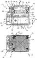
- Fig. 8 shows a sectional side view of a fan heater 10 in a second preferred embodiment, with a view of a holder 60 for supporting a heating element 30.
- a housing 11 substantially corresponds to the housing according to the first embodiment, therefore reference is made in this respect to the above description.
- the heating element 30 is provided here as a PTC element and formed as a filigree, latticed honeycomb body, which allows a sufficiently high air flow through the fan heater due to its lattice structure.
- FIG. 8 the layer structure of the fan heater 10 is shown.
- a fan 40, an air guide unit 50, the spring-mounted heating element 30 and an upper contact protection grid 19 are mounted one above the other in the housing 11.
- a lower contact protection grid (not visible) is preferably formed integrally with the housing 11.
- the blower 40 is in the Housing 11 stored.
- the air guide unit 50 is arranged. This is anchored by means of pin members 51 in the housing 11, so that a displacement of the air guide unit in the longitudinal direction L, but also the transverse displacement in the housing 11 can be avoided.
- the air guide unit 50 has on a lower side 53, with respect to the longitudinal direction L of the housing, a resilient means 55 which presses on the fan 40 and thus placed without play in the housing 11.
- a resilient means 55 which presses on the fan 40 and thus placed without play in the housing 11.
- protruding elements or receiving surfaces 52 are provided to receive the spring-mounted heating element 30 via this.
- the heating element 30 is mounted in this embodiment in a holder 60, which includes a plurality of separate receiving elements 61.
- the receiving elements 61 are attached directly to the heating element 30 and are supported by springs 63 on the housing 11 and / or other components of the fan heater.
- the heating element 30 thus equipped with the holder 60 rests on the protruding elements 52 of the air guiding unit 50 via the springs 63 extending on an underside 31 of the heating element 30.
- the heating element 30 is clamped between the air guide unit 50 and the contact protection grid 19, wherein the direct contact between the springs 63 and the air guide unit 50 and the contact protection grid 19 via the integrally formed with these protruding elements 20, 52 can be achieved.
- Upper and lower sides are defined with respect to the longitudinal direction L of the housing, respectively.
- the PTC element 30 is spaced apart from the housing 11 by virtue of the receiving elements 61 formed with the springs 63 and is mounted resiliently relative thereto. Since the heating element 30 is provided in this embodiment substantially as a square-shaped disc, each a receiving element 61 is mounted with a corresponding spring 63 at each corner of the heating element 30. This ensures a sufficiently secure hold of the heating element 30 at the same time resilient mounting.
- the resilient mounting also allows the compensation of transmitted from the housing 11 external effects, such. B. shocks, on the heating element 30, since the springs 63rd can absorb any transmitted via the housing 11 shocks.
- the protruding elements 52, 20 on the air guiding unit 50 and on the upper contact protection grid 19 are preferably formed integrally with these and / or as attachable to this, separate elements.
- the grid or the air guiding unit would then be formed with an attached or attachable frame as a protruding element, wherein the heating element would then be clamped over the frame.
- the frames can be provided both as separate elements or they are formed integrally with the grid or the air guiding unit.
- the springs 63 are formed as disk elements or as hemispherical elements which extend over both the bottom 31 and the top 32 of the heating element 30.
- the disk elements are accordingly attached via their respective center points to the receiving elements 61 and thus to the heating element 30. So they serve as a support on both sides.
- the heating element has both on its underside and on its upper side receiving elements and springs.
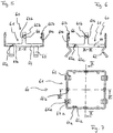
- Fig. 9 shows a top view in section of the heater 10 according to the second embodiment with the holder 60.
- the upper contact protection grid is removed so that the heating element 30 is visible.
- the heating element is designed here as a PTC element and has a lattice-shaped structure. Due to this configuration as a honeycomb body, a sufficient air flow through the heater is made possible, wherein the honeycomb body has a low flow resistance.
- the holder 60 at the four corners of the disk-shaped heating element 30 comprises the Receiving elements 61 and attached to these springs 63, wherein the springs are shown in section.
- Each receiving element 61 has at one end z.
- B. a kind of beak-shaped opening to store the heating element 30 therein. At another end is on the receiving element 61 z. B.
- the disc-shaped springs 63 which are shown in section, have a hole in their respective center, so that the springs can be attached to the respective receiving elements 61 via the pin-shaped pins in a straightforward manner.
- a head-shaped end of the pin prevents the respective springs 63 from sliding out of the corresponding receiving element 61.
- the blower 40 sucks z. B. on the bottom 12 of the fan heater 10 via an air inlet opening 14 air in the direction of arrow Pe.
- the air guide unit 50 serves for adequate air guidance or air turbulence in the heater fan 10. This ensures that the air sucked in by the fan 40 is expediently passed through the fan 10. Heating of the sucked-in air takes place via the heating element 30, so that in the heated state it is discharged via an air outlet opening 15 into the environment in the direction of the arrow Pa. In principle, the air flow direction could also provide opposite.
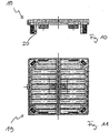
- the 10 and 11 show the upper contact protection grid 19 for the fan heater 10 according to the second embodiment.
- Fig. 10 represents a side view
- Fig. 11 shows the grid 19 in a plan view.
- Fig. 10 illustrates the protruding elements 20, which are integrally formed in this embodiment on the lower side of the grid integrally therewith.
- the grid 19 is located on the springs 63 of the holder 60 for the heating element 30. At the same time protects the grid 19 before the intervention in the interior of the fan heater 10th
- the embodiments just described can not be used alone.
- the embodiments can also be used cumulatively, ie that, for example, a fan heater housing formed with the resilient frame can be designed to accommodate a heating element provided with receiving elements and springs.
- the first shocks can already be imaged by the resilient mounting of the frame. Additional protection then forms the immediate arranged on the heating element springs.
- very heavily loaded fan heater offers such a solution.
- Fig. 9 the housing in this embodiment, on an outer side a fastening means 17 for receiving an adapter plate 70a, 70b, as in the FIGS. 12, 13, 14 and 15 are shown.
- the adapter plates 70a, 70b each have a fastening element 71, 72, so that the heating fan 10 can be fastened by means of this fastening element 71, 72 at a location provided for this purpose, for example in a control cabinet.
- the fastening device 17 on the housing 11 of the fan heater 10 is designed here as a latching hook, via which in each case an adapter plate 70a, 70b can be hooked to the housing wall, for example.
- the adapter plates 70a, 70b each have a corresponding counterpart, namely at least one projection and / or at least one recess.
- Fig. 12 Fig. 11 illustrates the adapter plate 70a formed with an elastic spring clip 71 for attachment to the fan heater housing 11 in a front view.
- Fig. 13 shows the adapter plate 70a in a side view.
- Another adapter plate 70b is Fig. 14 can be seen, in which case a second fastening element, namely in this case two slots 72, is shown.
- Fig. 15 also shows this adapter plate 70b in a side view. If different adapter plates are provided with different fastening elements, the suitable fastening element can be selected as required and fastened to the housing 11 of the fan heater 10 via the respective adapter plate.
- the spring clip 71 allows a clip attachment of the provided with the adapter plate 70 a fan heater 10 at the desired location, eg. B. on a designed rail in a cabinet.
- the heater fan 10 provided with the adapter plate 70b can be screwed in place.
- the fastening device 17 is formed on the housing 11 so that it also serves as a fastener.
- the fastening device 17 (not shown here completely) can be provided with the elastic and / or folding spring clip 71, to place the heater 10 directly at the desired location. An additional adapter plate is no longer necessary in this case.
- the receiving element or the receiving elements 61 of the holders 60 of the embodiments shown here are made of plastic.
- Plastics are extremely stable and break-resistant materials with low mass.
- receiving elements 61 made of plastic can ensure a secure hold of the heating element 30 and be stored without problems resilient.
- the spring elements 62 are formed according to the first embodiment of plastic.
- Plastic allows a stable design of resilient components with low mass.
- the springs 63 according to the second preferred embodiment are formed for example of plastic, for. B. of an elastomer, such as rubber or silicone.
- the integrally formed on the frame 64 spring elements 62 and the resilient means 55 of the air guide unit 50 are preferably integrally formed with each other, so that the spring elements 62 and the frame 64 and the resilient means 55 and the air guide unit 50 are made of the same material.
- a provided as a separate element resilient device may, for. B. also be formed as at least one metallic coil spring or the like resilient element. Also, a plate spring or a plate spring package for the play-free mounting of the fan by means of the resilient device is.
Landscapes
- Engineering & Computer Science (AREA)
- Thermal Sciences (AREA)
- Chemical & Material Sciences (AREA)
- Combustion & Propulsion (AREA)
- Mechanical Engineering (AREA)
- General Engineering & Computer Science (AREA)
- Physics & Mathematics (AREA)
- Resistance Heating (AREA)
- Direct Air Heating By Heater Or Combustion Gas (AREA)
- Housings, Intake/Discharge, And Installation Of Fluid Heaters (AREA)
- Cold Air Circulating Systems And Constructional Details In Refrigerators (AREA)
- Power Steering Mechanism (AREA)
- Structures Of Non-Positive Displacement Pumps (AREA)
- Electric Ovens (AREA)
- Devices For Blowing Cold Air, Devices For Blowing Warm Air, And Means For Preventing Water Condensation In Air Conditioning Units (AREA)
- Electric Stoves And Ranges (AREA)
Priority Applications (1)
| Application Number | Priority Date | Filing Date | Title |
|---|---|---|---|
| PL05808492T PL1825199T3 (pl) | 2004-11-29 | 2005-11-28 | Termowentylator |
Applications Claiming Priority (2)
| Application Number | Priority Date | Filing Date | Title |
|---|---|---|---|
| DE102004057530A DE102004057530A1 (de) | 2004-11-29 | 2004-11-29 | Heizlüfter |
| PCT/EP2005/012699 WO2006058687A1 (de) | 2004-11-29 | 2005-11-28 | Heizlüfter |
Publications (2)
| Publication Number | Publication Date |
|---|---|
| EP1825199A1 EP1825199A1 (de) | 2007-08-29 |
| EP1825199B1 true EP1825199B1 (de) | 2012-04-18 |
Family
ID=35842520
Family Applications (1)
| Application Number | Title | Priority Date | Filing Date |
|---|---|---|---|
| EP05808492A Expired - Lifetime EP1825199B1 (de) | 2004-11-29 | 2005-11-28 | Heizlüfter |
Country Status (10)
| Country | Link |
|---|---|
| US (1) | US7664379B2 (pl) |
| EP (1) | EP1825199B1 (pl) |
| JP (1) | JP4809360B2 (pl) |
| AT (1) | ATE554350T1 (pl) |
| BR (1) | BRPI0516651B1 (pl) |
| DE (1) | DE102004057530A1 (pl) |
| DK (1) | DK1825199T3 (pl) |
| ES (1) | ES2383133T3 (pl) |
| PL (1) | PL1825199T3 (pl) |
| WO (1) | WO2006058687A1 (pl) |
Cited By (1)
| Publication number | Priority date | Publication date | Assignee | Title |
|---|---|---|---|---|
| CN106500164A (zh) * | 2016-11-17 | 2017-03-15 | 刘开芹 | 电取暖炉 |
Families Citing this family (9)
| Publication number | Priority date | Publication date | Assignee | Title |
|---|---|---|---|---|
| CN2856836Y (zh) * | 2005-04-18 | 2007-01-10 | 壁基国际有限公司 | 一种电热风机 |
| EP2017546B1 (de) | 2007-07-18 | 2016-04-13 | Eberspächer catem GmbH & Co. KG | Verfahren zum Herstellen einer elektrischen Heizvorrichtung sowie elektrischer Heizvorrichtungen |
| DE102008030212A1 (de) | 2007-10-18 | 2009-04-23 | Stego-Holding Gmbh | Heizvorrichtung und Wärmetauscher |
| DE102010016177B4 (de) * | 2010-03-29 | 2013-10-24 | Rittal Gmbh & Co. Kg | Heizeinrichtung für den Einbau in einen Schaltschrank |
| US8526799B2 (en) * | 2011-01-18 | 2013-09-03 | Peet Shoe Dryer, Inc. | Air dehumidifier system for enclosures and safes |
| USD710487S1 (en) * | 2014-01-14 | 2014-08-05 | Hen-Yuan Lin | Static eliminator |
| JP1536463S (pl) * | 2014-12-16 | 2015-11-02 | ||
| CA162990S (en) * | 2015-06-18 | 2016-02-05 | Stelpro Design Inc | Heater housing |
| USD1028366S1 (en) * | 2023-08-28 | 2024-05-21 | Xu Wang | Nail vacuum cleaner |
Family Cites Families (27)
| Publication number | Priority date | Publication date | Assignee | Title |
|---|---|---|---|---|
| US2120795A (en) * | 1937-03-03 | 1938-06-14 | Air Devices Corp | Heater |
| US2260233A (en) * | 1940-02-23 | 1941-10-21 | Markel Electric Products Inc | Electric heater |
| US2429733A (en) * | 1945-04-10 | 1947-10-28 | Trent Inc | Electric heater of the fan type |
| US2606273A (en) * | 1950-09-09 | 1952-08-05 | Tropic Aire Inc | Combination space heater, fan, and air circulator |
| DE1727350U (de) * | 1956-02-24 | 1956-08-02 | Werner Diehl | Elektrischer heizluefter. |
| DE1741786U (de) * | 1956-08-31 | 1957-03-21 | Werner Diehl | Elektrischer heizluefter. |
| US2839657A (en) * | 1956-11-01 | 1958-06-17 | Commercial Controis Corp | Space heater |
| US2852657A (en) * | 1957-08-01 | 1958-09-16 | Markel Electric Products Inc | Heater |
| DE1811540U (de) * | 1959-11-30 | 1960-05-19 | Siemens Ag | Wand-fenster-luefter. |
| US3176117A (en) * | 1961-03-09 | 1965-03-30 | Berko Electric Mfg Corp | Electric space heater unit |
| DE7000378U (de) * | 1970-01-07 | 1970-09-10 | Siemens Elektrogeraete Gmbh | Einrichtung zur befestigung von heizelementen. |
| US3645512A (en) * | 1970-05-13 | 1972-02-29 | Scheu Mfg Co | Forced air heater |
| DE7628832U1 (de) * | 1976-09-15 | 1976-12-30 | Bosch-Siemens Hausgeraete Gmbh, 7000 Stuttgart | Elektrisches heizgeraet, insbesondere heizluefter |
| JPS5450229U (pl) * | 1977-09-14 | 1979-04-07 | ||
| JPS59161617A (ja) * | 1983-03-03 | 1984-09-12 | Matsushita Seiko Co Ltd | 電気スト−ブのヒ−タ割れ防止装置 |
| JPS60130330U (ja) * | 1984-02-10 | 1985-08-31 | 松下電器産業株式会社 | 一体型空気調和機のヒ−タ取付装置 |
| US4740670A (en) * | 1986-04-11 | 1988-04-26 | Taiwan Electric Heating Equipment Co. Ltd. | Electric fan heater for circulating and/or heating air |
| US4737616A (en) | 1986-05-12 | 1988-04-12 | Wen Ying Lee | Multi-function portable electric room heater having a removable heating cartridge |
| JPH035820Y2 (pl) * | 1986-05-20 | 1991-02-14 | ||
| US4739153A (en) * | 1986-06-02 | 1988-04-19 | Rendel Robert D | Wall mounted electric room heater |
| US4876436A (en) * | 1988-07-27 | 1989-10-24 | Gte Products Corporation | PTC air heater employing triangular PTC heating elements |
| US4928204A (en) * | 1989-02-28 | 1990-05-22 | Duracraft Corporation | Portable electrical appliance |
| JPH0727594Y2 (ja) * | 1989-10-31 | 1995-06-21 | シャープ株式会社 | セラミックヒータ |
| JPH0552426A (ja) * | 1991-08-20 | 1993-03-02 | Mitsubishi Electric Corp | 電気暖房器 |
| JPH0554909U (ja) * | 1991-12-26 | 1993-07-23 | シャープ株式会社 | 電気暖房器 |
| US5513296A (en) * | 1994-06-08 | 1996-04-30 | Holmes Products Corp. | Air heater with angled PTC heaters producing diverging heated airflow |
| EP1432287B1 (de) * | 2002-12-19 | 2006-06-21 | Catem GmbH & Co.KG | Elektrische Heizvorrichtung mit Gehäuse |
-
2004
- 2004-11-29 DE DE102004057530A patent/DE102004057530A1/de not_active Withdrawn
-
2005
- 2005-11-28 WO PCT/EP2005/012699 patent/WO2006058687A1/de not_active Ceased
- 2005-11-28 PL PL05808492T patent/PL1825199T3/pl unknown
- 2005-11-28 US US11/720,245 patent/US7664379B2/en not_active Expired - Fee Related
- 2005-11-28 BR BRPI0516651A patent/BRPI0516651B1/pt not_active IP Right Cessation
- 2005-11-28 ES ES05808492T patent/ES2383133T3/es not_active Expired - Lifetime
- 2005-11-28 DK DK05808492.2T patent/DK1825199T3/da active
- 2005-11-28 EP EP05808492A patent/EP1825199B1/de not_active Expired - Lifetime
- 2005-11-28 JP JP2007541867A patent/JP4809360B2/ja not_active Expired - Fee Related
- 2005-11-28 AT AT05808492T patent/ATE554350T1/de active
Cited By (2)
| Publication number | Priority date | Publication date | Assignee | Title |
|---|---|---|---|---|
| CN106500164A (zh) * | 2016-11-17 | 2017-03-15 | 刘开芹 | 电取暖炉 |
| CN106500164B (zh) * | 2016-11-17 | 2019-04-26 | 遵义强大博信知识产权服务有限公司 | 电取暖炉 |
Also Published As
| Publication number | Publication date |
|---|---|
| DE102004057530A1 (de) | 2006-06-01 |
| WO2006058687A1 (de) | 2006-06-08 |
| JP2008522120A (ja) | 2008-06-26 |
| BRPI0516651B1 (pt) | 2018-12-04 |
| DK1825199T3 (da) | 2012-07-23 |
| BRPI0516651A (pt) | 2008-09-16 |
| ATE554350T1 (de) | 2012-05-15 |
| US7664379B2 (en) | 2010-02-16 |
| JP4809360B2 (ja) | 2011-11-09 |
| US20080131102A1 (en) | 2008-06-05 |
| ES2383133T3 (es) | 2012-06-18 |
| EP1825199A1 (de) | 2007-08-29 |
| PL1825199T3 (pl) | 2012-09-28 |
Similar Documents
| Publication | Publication Date | Title |
|---|---|---|
| EP2111904B1 (de) | Filterlüfter mit einer Schnellbefestigungseinrichtung | |
| EP1825199B1 (de) | Heizlüfter | |
| DE3014110C2 (pl) | ||
| DE4243044A1 (en) | Compact inverter integral type motor combination - has inverter cooled with heat sink mounted on top of hexagonal motor case, and cooling fan driven by motor drive shaft | |
| DE4028000A1 (de) | Gehaeuse | |
| EP2182528B1 (de) | Vorrichtung zum Befestigen eines Lastwiderstandes | |
| DE3440166C2 (de) | Selbstregelndes elektrisches Heizgerät | |
| DE102009028808A1 (de) | Innenrahmen für Dunstabzugshaube und Dunstabzugshaube | |
| EP1335787B1 (de) | Vorrichtung zum filtern von luft | |
| EP1687571B1 (de) | Haushaltsgerät mit einer bedienleiste | |
| DE3210164C2 (de) | Vorrichtung zum Befestigen eines Lüfters in einer Gehäusewand eines elektrischen Gerätes | |
| DE19738504C5 (de) | Tür für ein Haushaltsgerät, insbesondere einen Haushaltsgarofen | |
| EP2735804B1 (de) | Hausgerätetür | |
| DE202006019690U1 (de) | Luftdurchtrittsvorrichtung | |
| DE102010002159B4 (de) | Vorrichtung zum Verbinden einer Antriebseinheit für eine Verstelleinrichtung eines Kraftfahrzeugsitzes mit der Festigkeitsstruktur des Kraftfahrzeugsitzes | |
| DE102010046315B4 (de) | Klimaanlage für Kraftfahrzeuge | |
| EP0077928A2 (de) | Halterungsanordnung für Steuerelemente von Kochherden | |
| EP2594851A2 (de) | Kochmuldenwanne mit Schutzeinheit | |
| EP1253032A2 (de) | Elektrische Heizeinrichtung mit in einem Rahmen gehaltenen Heizblock | |
| DE2129587B2 (de) | Vorrichtung zum halten und kontaktieren von thermisch belasteten keramikwiderstaenden | |
| EP2369240A1 (de) | Gargerätetüreinheit | |
| WO2007009511A1 (de) | Kontaktfeder in einem trägerrahmen eines antennenverstärkers eines fahrzeuges | |
| DE19603978A1 (de) | Lochkachel mit Lüftungs- oder Putzeinsatz für Kachelöfen | |
| DE9401864U1 (de) | Heizregister | |
| DE102010017840A1 (de) | Konsole zur Halterung eines Heizkörpers |
Legal Events
| Date | Code | Title | Description |
|---|---|---|---|
| PUAI | Public reference made under article 153(3) epc to a published international application that has entered the european phase |
Free format text: ORIGINAL CODE: 0009012 |
|
| 17P | Request for examination filed |
Effective date: 20070621 |
|
| AK | Designated contracting states |
Kind code of ref document: A1 Designated state(s): AT BE BG CH CY CZ DE DK EE ES FI FR GB GR HU IE IS IT LI LT LU LV MC NL PL PT RO SE SI SK TR |
|
| DAX | Request for extension of the european patent (deleted) | ||
| 17Q | First examination report despatched |
Effective date: 20101124 |
|
| GRAP | Despatch of communication of intention to grant a patent |
Free format text: ORIGINAL CODE: EPIDOSNIGR1 |
|
| GRAS | Grant fee paid |
Free format text: ORIGINAL CODE: EPIDOSNIGR3 |
|
| GRAA | (expected) grant |
Free format text: ORIGINAL CODE: 0009210 |
|
| AK | Designated contracting states |
Kind code of ref document: B1 Designated state(s): AT BE BG CH CY CZ DE DK EE ES FI FR GB GR HU IE IS IT LI LT LU LV MC NL PL PT RO SE SI SK TR |
|
| REG | Reference to a national code |
Ref country code: GB Ref legal event code: FG4D Free format text: NOT ENGLISH |
|
| REG | Reference to a national code |
Ref country code: CH Ref legal event code: EP |
|
| REG | Reference to a national code |
Ref country code: IE Ref legal event code: FG4D Free format text: LANGUAGE OF EP DOCUMENT: GERMAN |
|
| REG | Reference to a national code |
Ref country code: AT Ref legal event code: REF Ref document number: 554350 Country of ref document: AT Kind code of ref document: T Effective date: 20120515 |
|
| REG | Reference to a national code |
Ref country code: ES Ref legal event code: FG2A Ref document number: 2383133 Country of ref document: ES Kind code of ref document: T3 Effective date: 20120618 |
|
| REG | Reference to a national code |
Ref country code: DE Ref legal event code: R096 Ref document number: 502005012650 Country of ref document: DE Effective date: 20120621 |
|
| REG | Reference to a national code |
Ref country code: SE Ref legal event code: TRGR |
|
| REG | Reference to a national code |
Ref country code: DK Ref legal event code: T3 |
|
| REG | Reference to a national code |
Ref country code: NL Ref legal event code: T3 |
|
| LTIE | Lt: invalidation of european patent or patent extension |
Effective date: 20120418 |
|
| REG | Reference to a national code |
Ref country code: PL Ref legal event code: T3 |
|
| PG25 | Lapsed in a contracting state [announced via postgrant information from national office to epo] |
Ref country code: FI Free format text: LAPSE BECAUSE OF FAILURE TO SUBMIT A TRANSLATION OF THE DESCRIPTION OR TO PAY THE FEE WITHIN THE PRESCRIBED TIME-LIMIT Effective date: 20120418 Ref country code: IS Free format text: LAPSE BECAUSE OF FAILURE TO SUBMIT A TRANSLATION OF THE DESCRIPTION OR TO PAY THE FEE WITHIN THE PRESCRIBED TIME-LIMIT Effective date: 20120818 Ref country code: LT Free format text: LAPSE BECAUSE OF FAILURE TO SUBMIT A TRANSLATION OF THE DESCRIPTION OR TO PAY THE FEE WITHIN THE PRESCRIBED TIME-LIMIT Effective date: 20120418 Ref country code: CY Free format text: LAPSE BECAUSE OF FAILURE TO SUBMIT A TRANSLATION OF THE DESCRIPTION OR TO PAY THE FEE WITHIN THE PRESCRIBED TIME-LIMIT Effective date: 20120418 |
|
| PG25 | Lapsed in a contracting state [announced via postgrant information from national office to epo] |
Ref country code: SI Free format text: LAPSE BECAUSE OF FAILURE TO SUBMIT A TRANSLATION OF THE DESCRIPTION OR TO PAY THE FEE WITHIN THE PRESCRIBED TIME-LIMIT Effective date: 20120418 Ref country code: GR Free format text: LAPSE BECAUSE OF FAILURE TO SUBMIT A TRANSLATION OF THE DESCRIPTION OR TO PAY THE FEE WITHIN THE PRESCRIBED TIME-LIMIT Effective date: 20120719 Ref country code: LV Free format text: LAPSE BECAUSE OF FAILURE TO SUBMIT A TRANSLATION OF THE DESCRIPTION OR TO PAY THE FEE WITHIN THE PRESCRIBED TIME-LIMIT Effective date: 20120418 Ref country code: PT Free format text: LAPSE BECAUSE OF FAILURE TO SUBMIT A TRANSLATION OF THE DESCRIPTION OR TO PAY THE FEE WITHIN THE PRESCRIBED TIME-LIMIT Effective date: 20120820 |
|
| PG25 | Lapsed in a contracting state [announced via postgrant information from national office to epo] |
Ref country code: EE Free format text: LAPSE BECAUSE OF FAILURE TO SUBMIT A TRANSLATION OF THE DESCRIPTION OR TO PAY THE FEE WITHIN THE PRESCRIBED TIME-LIMIT Effective date: 20120418 Ref country code: SK Free format text: LAPSE BECAUSE OF FAILURE TO SUBMIT A TRANSLATION OF THE DESCRIPTION OR TO PAY THE FEE WITHIN THE PRESCRIBED TIME-LIMIT Effective date: 20120418 Ref country code: RO Free format text: LAPSE BECAUSE OF FAILURE TO SUBMIT A TRANSLATION OF THE DESCRIPTION OR TO PAY THE FEE WITHIN THE PRESCRIBED TIME-LIMIT Effective date: 20120418 |
|
| PLBE | No opposition filed within time limit |
Free format text: ORIGINAL CODE: 0009261 |
|
| STAA | Information on the status of an ep patent application or granted ep patent |
Free format text: STATUS: NO OPPOSITION FILED WITHIN TIME LIMIT |
|
| 26N | No opposition filed |
Effective date: 20130121 |
|
| REG | Reference to a national code |
Ref country code: DE Ref legal event code: R097 Ref document number: 502005012650 Country of ref document: DE Effective date: 20130121 |
|
| BERE | Be: lapsed |
Owner name: STEGO-HOLDING G.M.B.H. Effective date: 20121130 |
|
| REG | Reference to a national code |
Ref country code: CH Ref legal event code: PL |
|
| PG25 | Lapsed in a contracting state [announced via postgrant information from national office to epo] |
Ref country code: LI Free format text: LAPSE BECAUSE OF NON-PAYMENT OF DUE FEES Effective date: 20121130 Ref country code: BG Free format text: LAPSE BECAUSE OF FAILURE TO SUBMIT A TRANSLATION OF THE DESCRIPTION OR TO PAY THE FEE WITHIN THE PRESCRIBED TIME-LIMIT Effective date: 20120718 Ref country code: CH Free format text: LAPSE BECAUSE OF NON-PAYMENT OF DUE FEES Effective date: 20121130 |
|
| REG | Reference to a national code |
Ref country code: IE Ref legal event code: MM4A |
|
| PG25 | Lapsed in a contracting state [announced via postgrant information from national office to epo] |
Ref country code: BE Free format text: LAPSE BECAUSE OF NON-PAYMENT OF DUE FEES Effective date: 20121130 |
|
| PG25 | Lapsed in a contracting state [announced via postgrant information from national office to epo] |
Ref country code: IE Free format text: LAPSE BECAUSE OF NON-PAYMENT OF DUE FEES Effective date: 20121128 |
|
| REG | Reference to a national code |
Ref country code: AT Ref legal event code: MM01 Ref document number: 554350 Country of ref document: AT Kind code of ref document: T Effective date: 20121130 |
|
| PG25 | Lapsed in a contracting state [announced via postgrant information from national office to epo] |
Ref country code: AT Free format text: LAPSE BECAUSE OF NON-PAYMENT OF DUE FEES Effective date: 20121130 |
|
| PG25 | Lapsed in a contracting state [announced via postgrant information from national office to epo] |
Ref country code: MC Free format text: LAPSE BECAUSE OF NON-PAYMENT OF DUE FEES Effective date: 20121130 |
|
| PG25 | Lapsed in a contracting state [announced via postgrant information from national office to epo] |
Ref country code: LU Free format text: LAPSE BECAUSE OF NON-PAYMENT OF DUE FEES Effective date: 20121128 |
|
| PG25 | Lapsed in a contracting state [announced via postgrant information from national office to epo] |
Ref country code: HU Free format text: LAPSE BECAUSE OF FAILURE TO SUBMIT A TRANSLATION OF THE DESCRIPTION OR TO PAY THE FEE WITHIN THE PRESCRIBED TIME-LIMIT Effective date: 20051128 |
|
| REG | Reference to a national code |
Ref country code: FR Ref legal event code: PLFP Year of fee payment: 11 |
|
| REG | Reference to a national code |
Ref country code: FR Ref legal event code: PLFP Year of fee payment: 12 |
|
| REG | Reference to a national code |
Ref country code: FR Ref legal event code: PLFP Year of fee payment: 13 |
|
| PGFP | Annual fee paid to national office [announced via postgrant information from national office to epo] |
Ref country code: NL Payment date: 20181126 Year of fee payment: 14 |
|
| PGFP | Annual fee paid to national office [announced via postgrant information from national office to epo] |
Ref country code: PT Payment date: 20181210 Year of fee payment: 6 |
|
| PGFP | Annual fee paid to national office [announced via postgrant information from national office to epo] |
Ref country code: TR Payment date: 20181119 Year of fee payment: 14 |
|
| PGFP | Annual fee paid to national office [announced via postgrant information from national office to epo] |
Ref country code: CZ Payment date: 20191126 Year of fee payment: 15 |
|
| REG | Reference to a national code |
Ref country code: DK Ref legal event code: EBP Effective date: 20191130 |
|
| REG | Reference to a national code |
Ref country code: NL Ref legal event code: MM Effective date: 20191201 |
|
| PG25 | Lapsed in a contracting state [announced via postgrant information from national office to epo] |
Ref country code: NL Free format text: LAPSE BECAUSE OF NON-PAYMENT OF DUE FEES Effective date: 20191201 |
|
| PG25 | Lapsed in a contracting state [announced via postgrant information from national office to epo] |
Ref country code: DK Free format text: LAPSE BECAUSE OF NON-PAYMENT OF DUE FEES Effective date: 20191130 |
|
| PGFP | Annual fee paid to national office [announced via postgrant information from national office to epo] |
Ref country code: FR Payment date: 20201126 Year of fee payment: 16 Ref country code: SE Payment date: 20201123 Year of fee payment: 16 Ref country code: GB Payment date: 20201126 Year of fee payment: 16 Ref country code: IT Payment date: 20201120 Year of fee payment: 16 Ref country code: ES Payment date: 20201222 Year of fee payment: 16 Ref country code: DE Payment date: 20201127 Year of fee payment: 16 |
|
| PGFP | Annual fee paid to national office [announced via postgrant information from national office to epo] |
Ref country code: PL Payment date: 20201106 Year of fee payment: 16 |
|
| PG25 | Lapsed in a contracting state [announced via postgrant information from national office to epo] |
Ref country code: CZ Free format text: LAPSE BECAUSE OF NON-PAYMENT OF DUE FEES Effective date: 20201128 |
|
| REG | Reference to a national code |
Ref country code: DE Ref legal event code: R119 Ref document number: 502005012650 Country of ref document: DE |
|
| PG25 | Lapsed in a contracting state [announced via postgrant information from national office to epo] |
Ref country code: TR Free format text: LAPSE BECAUSE OF NON-PAYMENT OF DUE FEES Effective date: 20191128 |
|
| GBPC | Gb: european patent ceased through non-payment of renewal fee |
Effective date: 20211128 |
|
| PG25 | Lapsed in a contracting state [announced via postgrant information from national office to epo] |
Ref country code: SE Free format text: LAPSE BECAUSE OF NON-PAYMENT OF DUE FEES Effective date: 20211129 |
|
| PG25 | Lapsed in a contracting state [announced via postgrant information from national office to epo] |
Ref country code: GB Free format text: LAPSE BECAUSE OF NON-PAYMENT OF DUE FEES Effective date: 20211128 Ref country code: DE Free format text: LAPSE BECAUSE OF NON-PAYMENT OF DUE FEES Effective date: 20220601 |
|
| PG25 | Lapsed in a contracting state [announced via postgrant information from national office to epo] |
Ref country code: FR Free format text: LAPSE BECAUSE OF NON-PAYMENT OF DUE FEES Effective date: 20211130 |
|
| PG25 | Lapsed in a contracting state [announced via postgrant information from national office to epo] |
Ref country code: IT Free format text: LAPSE BECAUSE OF NON-PAYMENT OF DUE FEES Effective date: 20211128 |
|
| REG | Reference to a national code |
Ref country code: ES Ref legal event code: FD2A Effective date: 20230214 |
|
| PG25 | Lapsed in a contracting state [announced via postgrant information from national office to epo] |
Ref country code: ES Free format text: LAPSE BECAUSE OF NON-PAYMENT OF DUE FEES Effective date: 20211129 |
|
| PG25 | Lapsed in a contracting state [announced via postgrant information from national office to epo] |
Ref country code: PL Free format text: LAPSE BECAUSE OF NON-PAYMENT OF DUE FEES Effective date: 20211128 |