EP1824655B1 - Method of molding a microneedle - Google Patents
Method of molding a microneedle Download PDFInfo
- Publication number
- EP1824655B1 EP1824655B1 EP05853130A EP05853130A EP1824655B1 EP 1824655 B1 EP1824655 B1 EP 1824655B1 EP 05853130 A EP05853130 A EP 05853130A EP 05853130 A EP05853130 A EP 05853130A EP 1824655 B1 EP1824655 B1 EP 1824655B1
- Authority
- EP
- European Patent Office
- Prior art keywords
- mold
- microneedle
- mold insert
- polymeric material
- microneedles
- Prior art date
- Legal status (The legal status is an assumption and is not a legal conclusion. Google has not performed a legal analysis and makes no representation as to the accuracy of the status listed.)
- Not-in-force
Links
Images


Classifications
-
- B—PERFORMING OPERATIONS; TRANSPORTING
- B29—WORKING OF PLASTICS; WORKING OF SUBSTANCES IN A PLASTIC STATE IN GENERAL
- B29C—SHAPING OR JOINING OF PLASTICS; SHAPING OF MATERIAL IN A PLASTIC STATE, NOT OTHERWISE PROVIDED FOR; AFTER-TREATMENT OF THE SHAPED PRODUCTS, e.g. REPAIRING
- B29C45/00—Injection moulding, i.e. forcing the required volume of moulding material through a nozzle into a closed mould; Apparatus therefor
- B29C45/17—Component parts, details or accessories; Auxiliary operations
- B29C45/46—Means for plasticising or homogenising the moulding material or forcing it into the mould
- B29C45/56—Means for plasticising or homogenising the moulding material or forcing it into the mould using mould parts movable during or after injection, e.g. injection-compression moulding
- B29C45/568—Applying vibrations to the mould parts
-
- A—HUMAN NECESSITIES
- A61—MEDICAL OR VETERINARY SCIENCE; HYGIENE
- A61M—DEVICES FOR INTRODUCING MEDIA INTO, OR ONTO, THE BODY; DEVICES FOR TRANSDUCING BODY MEDIA OR FOR TAKING MEDIA FROM THE BODY; DEVICES FOR PRODUCING OR ENDING SLEEP OR STUPOR
- A61M37/00—Other apparatus for introducing media into the body; Percutany, i.e. introducing medicines into the body by diffusion through the skin
- A61M37/0015—Other apparatus for introducing media into the body; Percutany, i.e. introducing medicines into the body by diffusion through the skin by using microneedles
-
- B—PERFORMING OPERATIONS; TRANSPORTING
- B29—WORKING OF PLASTICS; WORKING OF SUBSTANCES IN A PLASTIC STATE IN GENERAL
- B29C—SHAPING OR JOINING OF PLASTICS; SHAPING OF MATERIAL IN A PLASTIC STATE, NOT OTHERWISE PROVIDED FOR; AFTER-TREATMENT OF THE SHAPED PRODUCTS, e.g. REPAIRING
- B29C45/00—Injection moulding, i.e. forcing the required volume of moulding material through a nozzle into a closed mould; Apparatus therefor
- B29C45/17—Component parts, details or accessories; Auxiliary operations
- B29C45/46—Means for plasticising or homogenising the moulding material or forcing it into the mould
- B29C45/56—Means for plasticising or homogenising the moulding material or forcing it into the mould using mould parts movable during or after injection, e.g. injection-compression moulding
- B29C45/561—Injection-compression moulding
-
- A—HUMAN NECESSITIES
- A61—MEDICAL OR VETERINARY SCIENCE; HYGIENE
- A61M—DEVICES FOR INTRODUCING MEDIA INTO, OR ONTO, THE BODY; DEVICES FOR TRANSDUCING BODY MEDIA OR FOR TAKING MEDIA FROM THE BODY; DEVICES FOR PRODUCING OR ENDING SLEEP OR STUPOR
- A61M37/00—Other apparatus for introducing media into the body; Percutany, i.e. introducing medicines into the body by diffusion through the skin
- A61M37/0015—Other apparatus for introducing media into the body; Percutany, i.e. introducing medicines into the body by diffusion through the skin by using microneedles
- A61M2037/0053—Methods for producing microneedles
-
- B—PERFORMING OPERATIONS; TRANSPORTING
- B29—WORKING OF PLASTICS; WORKING OF SUBSTANCES IN A PLASTIC STATE IN GENERAL
- B29C—SHAPING OR JOINING OF PLASTICS; SHAPING OF MATERIAL IN A PLASTIC STATE, NOT OTHERWISE PROVIDED FOR; AFTER-TREATMENT OF THE SHAPED PRODUCTS, e.g. REPAIRING
- B29C45/00—Injection moulding, i.e. forcing the required volume of moulding material through a nozzle into a closed mould; Apparatus therefor
- B29C2045/0094—Injection moulding, i.e. forcing the required volume of moulding material through a nozzle into a closed mould; Apparatus therefor injection moulding of small-sized articles, e.g. microarticles, ultra thin articles
-
- B—PERFORMING OPERATIONS; TRANSPORTING
- B29—WORKING OF PLASTICS; WORKING OF SUBSTANCES IN A PLASTIC STATE IN GENERAL
- B29C—SHAPING OR JOINING OF PLASTICS; SHAPING OF MATERIAL IN A PLASTIC STATE, NOT OTHERWISE PROVIDED FOR; AFTER-TREATMENT OF THE SHAPED PRODUCTS, e.g. REPAIRING
- B29C2791/00—Shaping characteristics in general
- B29C2791/004—Shaping under special conditions
- B29C2791/008—Using vibrations during moulding
-
- B—PERFORMING OPERATIONS; TRANSPORTING
- B29—WORKING OF PLASTICS; WORKING OF SUBSTANCES IN A PLASTIC STATE IN GENERAL
- B29C—SHAPING OR JOINING OF PLASTICS; SHAPING OF MATERIAL IN A PLASTIC STATE, NOT OTHERWISE PROVIDED FOR; AFTER-TREATMENT OF THE SHAPED PRODUCTS, e.g. REPAIRING
- B29C45/00—Injection moulding, i.e. forcing the required volume of moulding material through a nozzle into a closed mould; Apparatus therefor
- B29C45/17—Component parts, details or accessories; Auxiliary operations
- B29C45/26—Moulds
- B29C45/2669—Moulds with means for removing excess material, e.g. with overflow cavities
-
- B—PERFORMING OPERATIONS; TRANSPORTING
- B29—WORKING OF PLASTICS; WORKING OF SUBSTANCES IN A PLASTIC STATE IN GENERAL
- B29C—SHAPING OR JOINING OF PLASTICS; SHAPING OF MATERIAL IN A PLASTIC STATE, NOT OTHERWISE PROVIDED FOR; AFTER-TREATMENT OF THE SHAPED PRODUCTS, e.g. REPAIRING
- B29C45/00—Injection moulding, i.e. forcing the required volume of moulding material through a nozzle into a closed mould; Apparatus therefor
- B29C45/17—Component parts, details or accessories; Auxiliary operations
- B29C45/26—Moulds
- B29C45/34—Moulds having venting means
-
- B—PERFORMING OPERATIONS; TRANSPORTING
- B29—WORKING OF PLASTICS; WORKING OF SUBSTANCES IN A PLASTIC STATE IN GENERAL
- B29L—INDEXING SCHEME ASSOCIATED WITH SUBCLASS B29C, RELATING TO PARTICULAR ARTICLES
- B29L2031/00—Other particular articles
- B29L2031/753—Medical equipment; Accessories therefor
- B29L2031/7544—Injection needles, syringes
-
- B—PERFORMING OPERATIONS; TRANSPORTING
- B29—WORKING OF PLASTICS; WORKING OF SUBSTANCES IN A PLASTIC STATE IN GENERAL
- B29L—INDEXING SCHEME ASSOCIATED WITH SUBCLASS B29C, RELATING TO PARTICULAR ARTICLES
- B29L2031/00—Other particular articles
- B29L2031/756—Microarticles, nanoarticles
Definitions
- the present invention relates to methods of molding microneedles. In one aspect, the present invention relates to methods of molding microneedle arrays.
- stratum corneum the outermost layer of the skin.
- Devices including arrays of relatively small structures have been disclosed for use in connection with the delivery of therapeutic agents and other substances through the skin and other surfaces.
- the devices are typically pressed against the skin in order to pierce the stratum corneum such that the therapeutic agents and other substances can pass through that layer and into the tissues below.
- microneedles are very fine structures that can be difficult to prepare in a polymeric molding process and the known microneedle molding processes all have certain disadvantages.
- the present invention provides, among other things, an improved molding process for preparing microneedle arrays comprising a combination of injection and compression molding processes.
- the ability to reproduce the mold shape in the final molded part, reliably produce microneedles of a consistent height, and produce microneedle arrays in an economical fashion are among the desirable features of this invention.
- this invention is particularly suitable for molding microneedles made from tough engineering grade plastics.
- the present invention is a method of molding a microneedle using a mold apparatus that comprises a mold insert having the negative image of at least one microneedle, a compression core, sidewalls having an injection gate, and a mold housing configured to allow a reciprocal motion between the mold insert and the compression core.
- the mold apparatus has an open position and a closed position. The mold apparatus is placed in the closed position and polymeric material is injected through the injection gate into the closed mold apparatus. The injected polymeric material is compressed between the mold insert and the compression core by a reciprocal motion between the compression core and the mold insert. The mold is opened and a molded microneedle is removed from the mold.
- the present invention is a method of molding a microneedle using a mold apparatus that comprises a mold insert having the negative image of at least one microneedle, a compression core, and a mold housing configured to allow a reciprocal motion between the mold insert and the compression core.
- the mold apparatus has an open position and a closed position.
- the mold insert is heated to a temperature of greater than or equal to 200 °F (93.3 °C).
- the mold apparatus is placed in the closed position and polymeric material is injected into the closed mold apparatus.
- the injected polymeric material is compressed between the mold insert and the compression core by a reciprocal motion between the compression core and the mold insert.
- the mold is opened and a molded microneedle is removed from the mold.
- the present invention is a method of molding a microneedle using a mold apparatus that comprises a mold insert having the negative image of at least one microneedle, a compression core, and a mold housing configured to allow a reciprocal motion between the mold insert and the compression core.
- the mold apparatus has an open position and a closed position.
- the mold apparatus is placed in the closed position and polymeric material is injected into the closed mold apparatus.
- the polymeric material is characterized by a melt-flow index greater than about 5 g/10 minutes when measured by ASTM D1238 at conditions of 300 °C and 1.2 kg weight.
- the injected polymeric material is compressed between the mold insert and the compression core by a reciprocal motion between the compression core and the mold insert so that the negative image of the at least one microneedle is substantially completely filled with the injected polymeric material.
- the mold is opened and a molded microneedle is removed from the mold.
- the present invention is a method of molding a microneedle using a mold apparatus that comprises a mold insert having the negative image of at least one microneedle, a compression core, and a mold housing configured to allow a reciprocal motion between the mold insert and the compression core.
- the mold apparatus has an open position and a closed position. The mold apparatus is placed in the closed position and polymeric material is injected into the closed mold apparatus. The injected polymeric material is compressed between the mold insert and the compression core by a reciprocal motion between the compression core and the mold insert. The mold is opened and a molded microneedle is removed from the mold.
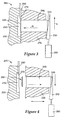
- Figure 1 shows a mold apparatus in the open position.
- the mold apparatus comprises a mold housing formed from a first mold member 220 and a second mold member 230.
- the first mold member 220 partially surrounds a mold insert 210 which has the negative image of at least one microneedle.
- the mold insert 210 has the negative image of a microneedle array.
- the second mold member 230 partially surrounds a compression core 240, which is conventionally in the form of a piston.
- the mold housing is configured to allow a reciprocal motion between the mold insert 210 and the compression core 240.
- a wedge 250 that is driven by a hydraulic cylinder 260 transmits force to the compression core 240 via a core-wedge connection 245.
- the connection 245 is shown as a separate piece, but may be integrally formed as part of the compression core 240 or it may be any conventional linkage that can transmit mechanical force based on the motion of the wedge 250.
- An input line 280 is used to input molten polymeric material through an injection gate 270 and into the mold cavity that is formed when the mold apparatus is in the closed position.
- the mold apparatus 200 is shown in the closed position in Figure 2 .
- the arrow, identified as "C" indicates the direction of motion of the right portion of the apparatus which comprises the second mold member 230, compression core 240, and wedge 250, although it should be noted the orientation of the mold apparatus as shown is arbitrary and may be rotated or inverted as desired.
- the left portion of the mold apparatus comprises the first mold member 220 and the mold insert 210. In the closed position, the left and right portions of the apparatus rest against each other by their joint face, allowing the polymeric material to be injected into the mold apparatus. The left portion and the right portion are spaced apart in the open position, making it possible to remove the molded microneedle from the mold.
- the mold apparatus 200 in the closed position defines a mold cavity 290.
- the shape of the mold cavity 290 is defined on one major surface by the mold insert 210 and on an opposing major surface by the near end 275 of the compression core 240.
- the second mold member 230 and the mold insert 210 also define sidewalls 285.
- the injection gate 270 is an opening on the sidewalls 285.
- the sidewalls 285 may be formed entirely by the mold insert 210, that is, the near end 275 of the compression core 240 would be flush with the ends of the second mold member 230.
- the sidewalls 285 may be formed entirely by the second mold member 230, that is, the right hand face of the mold insert would be flush with the surface of the first mold member 220.
- the sidewalls 285 may be formed by any combination of the above descriptions and need not be a separate piece, but are rather intended to define the sides of the mold cavity 290 formed by the interrelation of all of the parts of the mold apparatus. Other designs are equally suitable so long as the mold apparatus defines a mold cavity which may be filled with molten polymeric material under pressure.
- molten polymeric material is injected through the input line 280 and injection gate 270 to partially fill the mold cavity 290.
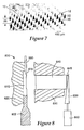
- the hydraulic cylinder 260 moves the wedge 250 in the direction of the arrow identified as 'A' in Figure 3 to place the mold apparatus 200 in a compressed position. Movement of the wedge 250 causes corresponding movement of the compression core 240 in the direction of the arrow identified as 'B', that is, there is a reciprocal motion between the compression core 240 and the mold insert 210.
- the molten polymeric material is thus compressed within the mold cavity 290 thereby aiding in filling the negative image of the microneedle array in the mold insert 210.
- the mold apparatus is subsequently opened, as shown in Figure 4 , and the arrows show the direction of motion of the various parts (compression core 240, wedge 250, second mold member 230) returning to their open positions.
- a molded microneedle array 295 is then ejected from the open mold apparatus by any conventional method, such as with the use of ejector pins (not shown).
- the cycle shown in Figures 1 to 4 may subsequently be repeated as desired to produce multiple parts.
- the mold apparatus may be configured so as to have multiple, individual mold cavities.
- Each mold cavity has a negative image of a microneedle array, such that the result of a single cycle of injection and compression produces multiple microneedle arrays.
- the number of individual mold cavities may be, for example, 4 or more, often 8 or more, and in some instances 32 or more.
- the injection pressure with which the molten polymeric material is injected into the mold cavities may be adjusted accordingly depending on the shape, size, and number of cavities being filled.
- the compressive force to the individual mold cavities may be provided by a single device, such as a hydraulic cylinder, which is configured so as to distribute the compressive force evenly across the different cavities. Alternatively, more than one device may be used to supply compressive force.
- a hydraulic cylinder may be provided to supply compressive force to each mold cavity, to every two mold cavities, or to every 4 mold cavities.
- the mold insert 210 is heated to a temperature of greater than or equal to about 200 °F (93.3 °C), and sometimes to a temperature greater than or equal to 250 °F (121 °C). Heating of the mold insert may be desirable to aid in flow of the injected polymeric material into the fine structures of the mold insert. In particular, heating of the mold insert may allow for use of reduced compressive forces and/or may decrease cycle times. In a preferred embodiment, the temperature of the mold insert 210 is held substantially constant. The mold insert is preferably maintained at or below the temperature at which the polymeric material will form a part with sufficient rigidity to allow the part to be detached from the mold and handled without significant distortion or warping occurring.
- Heating of the mold insert can be accomplished by any known conventional means, for example, by indirectly heating another part of the mold apparatus, such as the first mold member, and allowing the heat to transfer to the mold insert.
- the temperature of the mold insert 210 may be cycled so that it is at a higher temperature during the filling part of the cycle and at a lower temperature when the part is ejected. This so-called 'thermocycling' process may aid in filling and removal of the part. Additional details on thermocycling molding may be found in U.S. Patent No. 5,376,317 (Maus et al. ).
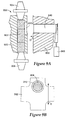
- the mold apparatus includes an overflow vent 400 connected to the mold cavity 290, as shown in Figure 5A .
- Molten polymeric material fed through the input line 280 passes through the injection gate 270 and into the mold cavity 290.
- the arrow shows the general direction of flow of polymeric material from the input line 280 into the mold cavity 290.
- the polymeric material fills the mold cavity it displaces air that was in the cavity. In one embodiment, little or no displaced air becomes trapped in pockets within the mold cavity or within the negative images of microneedles in the mold insert.
- the overflow vent 400 serves as an exit gate to allow displaced air to leave the cavity thus allowing for more uniform filling of the mold cavity with polymeric material.
- the overflow vent may be positioned anywhere on the outer surface of the mold cavity. In one embodiment the overflow vent is positioned along the sidewalls of the mold cavity. In the embodiment shown in Figure 5A , the overflow vent 400 is positioned along the sidewall and opposed to the injection gate 270.
- Figure 5B shows a detailed side view of polymeric material 282 within the input line 280, polymeric material 402 within the overflow vent 400, and polymeric material in the form of a microneedle array 295within the mold cavity 290.
- the material is selected so that it is capable of forming relatively rigid and tough microneedles that resist bending or breaking when applied to a skin surface.
- the polymeric material has a melt-flow index greater than about 5 g/10 minutes when measured by ASTM D1238 at conditions of 300 °C and 1.2 kg weight. The melt-flow index is often greater than or equal to about 10 g/10 minutes and sometimes greater than or equal to about 20 g/10 minutes. In another embodiment, the tensile elongation at break as measured by ASTM D638 (2.0 in/minute) is greater than about 100 percent.
- the impact strength as measured by ASTM D256, "Notched Izod", (73°F) is greater than about 5 ft-1b/inches.
- suitable materials include polycarbonate, polyetherimide, polyethylene terephthalate, and mixtures thereof. In one embodiment the material is polycarbonate.
- the compressive force is supplied by a wedge in the illustrated embodiment, any known conventional method of applying force may be used to provide compressive force to the mold cavity.
- the compression core may have any suitable shape that forms a major surface of the mold cavity and allows for application of compressive force to the material in the mold cavity.
- the compression core may be in the form of a piston or pin, and desirably the face of the piston or pin is the same diameter as the part to be formed.
- many conventional methods for applying force may be utilized, such as, for example, using a hydraulic pancake cylinder.
- microneedle arrays with molded microneedles integrally formed with a substrate may be prepared.
- Figure 6 shows such a microneedle array 10.
- a portion of the array 10 is illustrated with microneedles 12 protruding from a microneedle substrate surface 16.
- the microneedles 12 may be arranged in any desired pattern 14 or distributed over the substrate surface 16 randomly.
- the microneedles 12 are arranged in uniformly spaced rows placed in a rectangular arrangement.
- arrays of the present invention have a patient-facing surface area of more than about 0.1 cm 2 and less than about 20 cm 2 , in some instances, more than about 0.5 cm 2 and less than about 5 cm 2 .
- a portion of the substrate surface 16 is non-patterned.
- the non-patterned surface has an area of more than about 1 percent and less than about 75 percent of the total area of the device surface that faces a skin surface of a patient.
- the non-patterned surface has an area of more than about 0.10 square inch (0.65 cm 2 ) to less than about 1 square inch (6.5 cm 2 ).
- the microneedles are disposed over substantially the entire surface area of the array 10. The thickness of the substrate surface may vary depending on the desired end use of the microneedle array.
- the substrate surface may be less than 200 mil (0.51 cm) in thickness, often less than 100 mil (0.25 cm) in thickness, and sometimes less than 50 mil (0.13 cm) in thickness.
- the substrate surface is typically more than 1 mil (25.4 ⁇ m) in thickness, often more than 5 mil (127 ⁇ m) in thickness, and sometimes more than 10 mil (203 ⁇ m) in thickness.
- the microneedles are typically less than 1000 microns in height, often less than 500 microns in height, and sometimes less than 250 microns in height.
- the microneedles are typically more than 20 microns in height, often more than 50 microns in height, and sometimes more than 125 microns in height.
- the microneedles may be characterized by an aspect ratio.
- aspect ratio is the ratio of the height of the microneedle (above the surface surrounding the base of the microneedle) to the maximum base dimension, that is, the longest straight-line dimension that the base occupies (on the surface occupied by the base of the microneedle).
- the maximum base dimension would be the diagonal line connecting opposed corners across the base.
- Microneedles of the present invention typically have an aspect ratio of between about 2:1 to about 5:1 and sometimes between about 2.5:1 to about 4:1.
- microneedle arrays prepared by methods of the present invention may comprise any of a variety of configurations, such as those described in the following patents and patent applications, the disclosures of which are herein incorporated by reference.
- One embodiment for the microneedle devices comprises the structures disclosed in U. S. Patent Application Publication No. 2003/0045837 .
- the disclosed microstructures in the aforementioned patent application are in the form of microneedles having tapered structures that include at least one channel formed in the outside surface of each microneedle.
- the microneedles may have bases that are elongated in one direction.
- the channels in microneedle with elongated bases may extend from one of the ends of the elongated bases towards the tips of the microneedles.
- the channels formed along the sides of the microneedles may optionally be terminated short of the tips of the microneedles.
- the microneedle arrays may also include conduit structures formed on the surface of the substrate on which the microneedle array is located. The channels in the microneedles may be in fluid communication with the conduit structures.
- Still another embodiment for the microneedle arrays comprises the structures disclosed in U. S. Patent No. 6,312,612 (Sherman, et al. ) which describes tapered structures having a hollow central channel. Still another embodiment for the microneedle arrays comprises the structures disclosed in International Publication No. WO 00/74766 (Gartstein, et al. ) which describes hollow microneedles having at least one longitudinal blade at the top surface of tip of the microneedle.
- each of the microneedles 12 includes a base 20 on the substrate surface 16, with the microneedle terminating above the substrate surface in a tip 22.
- the microneedle base 20 shown in Figure 7 is rectangular in shape, it will be understood that the shape of the microneedles 12 and their associated bases 20 may vary with some bases, e.g., being elongated along one or more directions and others being symmetrical in all directions.
- the base 20 may be formed in any suitable shape, such as a square, rectangle, or oval. In one embodiment the base 20 may have an oval shape (i.e., that is elongated along an elongation axis on the substrate surface 16).
- the height 26 of the microneedles 12 may be measured from the substrate surface 16. It may be preferred, for example, that the base-to-tip height of the microneedles 12 be about 500 micrometers or less as measured from the substrate surface 16. Alternatively, it may be preferred that the height 26 of the microneedles 12 is about 250 micrometers or less as measured from the base 20 to the tip 22. It may also be preferred that the height of molded microneedles is greater than about 90%, and more preferably greater than about 95%, of the height of the microneedle topography in the mold insert. The microneedles may deform slightly or elongate upon ejection from the mold insert.
- the height of the molded microneedles is less than about 115%, and more preferably less than about 105%, of the height of the microneedle topography in the mold.
- the general shape of the microneedles of the present invention may be tapered.
- the microneedles 12 may have a larger base 20 at the substrate surface 16 and extend away from the substrate surface 16, tapering to a tip 22.
- the shape of the microneedles is pyramidal.
- the shape of the microneedles is generally conical.
- the microneedles have a defined tip bluntness, wherein the microneedles have a flat tip comprising a surface area measured in a plane aligned with the base of about 20 square micrometers or more and 100 square micrometers or less.
- the surface area of the flat tip will be measured as the cross-sectional area measured in a plane aligned with the base, the plane being located at a distance of 0.98h from the base, where h is the height of the microneedle above the substrate surface measured from base to tip.
- the motion of the compression core 240 in Figures 2 and 3 is shown in an exaggerated fashion for purposes of illustration.
- the bulk of the mold cavity 290 is substantially filled prior to compression and the compression step is performed largely to fill the negative images of microneedles 12 in the mold insert 210.
- the motion of the compression core is generally selected so as to displace a volume similar in size or larger than the volume of the mold cavity that remains unfilled by the initial injection step.
- Displacement of a larger volume may also be desirable in order to account for material that escapes the mold cavity as parting line flash or to account for mold plate deflections.
- the motion of the compression core and the resulting volume displaced may be adjusted depending on a number of parameters, including the size of the mold cavity, the shape and number of features in the mold cavity, the amount of the mold cavity filled by the initial injection step, and the type of material molded. Since the microneedle image(s) in the mold insert is relatively small both in height and volume, the motion of the compression core, that is the compression stroke, is typically between about 0.001 to 0.010 inches (25 ⁇ m to 250 ⁇ m), often between 0.002 to 0.008 inches (50 ⁇ m to 200 ⁇ m), and sometimes between 0.003 to 0.006 inches (75 ⁇ m to 150 ⁇ m).
- the applied compressive force is typically greater than 5000 psi (34500 kPa), sometimes greater than 30000 psi (207000 kPa), and often greater than 60000 psi (414000 kPa). Additional details regarding injection-compression molding may be found in U. S. Patent Nos. 4,489,033 (Uda et al. ), 4,515,543 (Hamner ), and 6,248,281 (Abe et al. ).
- the negative image(s) of the at least one microneedle is substantially completely filled with injected polymeric material prior to opening the mold and ejecting the part.
- the molded microneedle should have a height greater than about 90 percent of the corresponding height of the microneedle topography in the mold insert.
- the molded microneedle has a height greater than about 95 percent of the corresponding height of the microneedle topography in the mold insert. It is preferable that the molded microneedle has a height substantially the same (e.g., 95 percent to 105 percent) as the corresponding height of the microneedle topography in the mold insert.
- Mold inserts suitable for use in the present invention may be made by any known conventional method.
- a positive 'master' is used to form the mold insert.
- the positive master is made by forming a material into a shape in which the microneedle array will be molded.
- This master can be machined from materials that include, but are not limited to, copper, steel, aluminum, brass, and other heavy metals.
- the master can also be made from thermoplastic or thermoset polymers that are compression formed using silicone molds.
- the master is fabricated to directly replicate the microneedle array that is desired.
- the positive master may be prepared by a number of methods and may have microneedles of any of a variety of shapes, for example, pyramids, cones, or pins.
- the protrusions of the positive master are sized and spaced appropriately, such that the microneedle arrays formed during molding using the subsequently formed mold insert have substantially the same topography as the positive master.
- a positive master may be prepared by direct machining techniques such as diamond turning, disclosed in U. S. Patent No. 5,152,917 (Pieper, et al. ) and U. S. Patent No. 6,076,248 (Hoopman, et al. ).
- a microneedle array can be formed in a metal surface, for example, by use of a diamond turning machine, from which is produced a mold insert having an array of cavity shapes.
- the metal positive master can be manufactured by diamond turning to leave the desired shapes in a metal surface which is amenable to diamond turning, such as aluminum, copper or bronze, and then nickel plating the grooved surface to provide the metal master.
- a mold insert made of metal can be fabricated from the positive master by electroforming.
- the present disclosure provides a method of molding microneedles whereby high frequency acoustic energy, such as ultrasonic energy, is applied to the mold apparatus 200.
- High frequency acoustic energy such as ultrasonic energy
- ultrasonic energy is applied to the mold insert 210 or input line in conjunction with the combination of injection and compression molding, for example, as illustrated in Figures 1 to 4 .
- the use of ultrasonic energy prevents the polymeric material from substantially cooling before filling the narrow channels, since the polymeric material can be prone to "skin over" or solidify in the channel prior to complete filling and thus block further flow of molten material.
- the compressive force used in conjunction with ultrasonic energy is typically greater than 2000 psi (13800 kPa), often greater than 5000 psi (34500 kPa), and sometimes greater than 10000 psi (69000 kPa).
- an ultrasonic horn 802 may be placed up against one side of the mold insert 810.
- the first mold member 820 supports the horn 802, the mold insert 810 and the input line 880.
- the second mold member 830 is used as described above.
- Ultrasonic energy from the horn 802 may be applied at any time while the mold apparatus is in the closed position, such as during the step of injecting polymeric material or during the step of compressing the injected polymeric material.
- ultrasonic energy is initially applied after the start of the step of injecting polymeric material.
- ultrasonic energy is initially applied before the compressing step.
- the application of ultrasonic energy is preferably stopped before the mold apparatus is opened.
- the ultrasonic energy may be applied for a time period of about 0.5 to 5 seconds and sometimes for a time period of about 0.5 to 2 seconds.
- the ultrasonic horn 902 in Figures 9A , B is shown as a flat, cross-shaped member.
- Ultrasonic boosters 904, 906 are coupled to opposing sides of the ultrasonic horn 902.
- the mold insert 910 is shown positioned such that it is placed over one "lobe" of the cross-shaped horn.
- the application of power from the boosters 904, 906 causes application of energy in a direction of shear across the face of the mold insert 908 as shown by the two-sided arrow labelled E in Figure 9B .
- the face of the ultrasonic horn 902 makes a flush contact with the back surface of the mold insert 910.
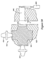
- the mold insert 910 may be partially or fully recessed into the surface of the ultrasonic horn 902 (as is shown in Figure 10 ). The remainder of the mold apparatus is operated as described above.
- the mold apparatus 900 would also have one or more input lines and injection gates (not shown) suitable for introducing polymeric material into the mold cavity that is formed when the apparatus 900 is placed into a closed position.
- Ultrasonic energy from the horn 902 may be applied during the step of injecting polymeric material or during the step of compressing the injected polymeric material. The application of ultrasonic energy may be stopped before the mold apparatus is opened.
- the ultrasonic horn 602 may be a flat, cross-shaped member aligned as shown in Figure 10 .
- the mold insert 670 is shown partially recessed into one surface of the ultrasonic horn 602.
- the ultrasonic boosters 604, 606 are shown aligned on adjacent sides of the ultrasonic horn 602.
- a converter (not shown) is coupled to booster 606 to drive ultrasonic vibration along an axis parallel to the length of the microneedle cavities.
- the remainder of the mold apparatus is operated as described above.
- Ultrasonic energy from the horn 602 may be applied during the step of injecting polymeric material or during the step of compressing the injected polymeric material. The application of ultrasonic energy may be stopped before the mold apparatus is opened.
- the arrangement of ultrasonic boosters may be varied, for example, by placing boosters against each lobe of the ultrasonic horn that does not contact the mold insert, or by placing boosters against other surfaces of the ultrasonic horn.
- the ultrasonic horn may have any of a number of other conventional shapes suitable for transmitting ultrasonic energy to the mold apparatus. For example, a stepped cylinder (as shown in Figure 8 ), a stepped bar, or a rectangular bar may be used.
- Ultrasonic energy may be applied in a direction parallel to the plane of the microneedle array, perpendicular to the plane of the microneedle array, or at some other angle with respect to the microneedle array.
- a solid second mold member 530 may be used to press up against the first mold member 520, thereby forming a mold cavity along with the mold insert 510.
- the ultrasonic horn 502 and boosters 504,506 are used as described above to facilitate filling of injected polymeric material into the mold insert.
- the mold insert 510 is shown positioned such that it is placed over one "lobe" of the cross-shaped horn.
- the first mold member 520 and second mold member 530 may be optionally configured so that multiple mold inserts may be held in place against the ultrasonic horn 502.
- Figure 11B shows where three optional mold inserts 512 may be placed against the horn 502.
- the mold apparatus 500 would also have one or more input lines and injection gates (not shown) suitable for introducing polymeric material into the mold cavity that is formed when the apparatus 500 is placed into a closed position. Placement of two or more mold inserts against the ultrasonic horn could be employed in any of the foregoing embodiments taking into account the size of the mold inserts and the size of the ultrasonic horn. In embodiments where a compression core is employed it may be advantageous to use an individual compression core in conjunction with each mold insert or alternatively a single compression core may be sized and gated appropriately to simultaneously provide compressive force to more than one mold insert.
- the ultrasonic energy used may vary in frequency, but is typically defined as having a frequency greater than or equal to about 20,000 Hz. Although any ultrasonic frequency may be used, it will typically be less than 60,000 Hz, often less than 40,000 Hz, and sometimes less than 30,000 Hz. In one illustrative example, the frequency is about 20,000 Hz. Although the specific examples of Figures 8 to 11 described above refer to ultrasonic energy, relatively high frequency acoustic energy with a frequency greater than about 5,000 Hz is also suitable to provide vibrational energy to aid in filling the narrow channels of the mold insert. In one illustrative example, the acoustic energy has a frequency of between about 10,000 Hz and 60,000 Hz, often between about 15,000 Hz and 40,000 Hz.
- Ultrasonic energy may be applied using an ultrasonic horn.
- the amplitude of motion of the ultrasonic horn is typically less than about 0.005 inch (127 ⁇ m) and is often less than about 0.002 inch (51 ⁇ m). In one illustrative example, the amplitude of motion of the ultrasonic horn may be between about 0.0005 inch (12.7 ⁇ m) and 0.001 inch (38.1 ⁇ m).
- the ultrasonic energy is generally supplied by using a power source that supplies electrical energy of the desired frequency. Power sources will typically provide from 500 to 3000 W power.
- the electrical energy is fed to a converter or transducer which transforms the electrical energy into mechanical energy with the same frequency. The mechanical vibrations are then amplified or boosted and transmitted by the ultrasonic horn.
- the ultrasonic horn is situated with respect to the mold apparatus so that vibrational energy is transmitted to the mold apparatus. It may be desirable, for example, for the ultrasonic horn to be in direct contact with a portion of the mold apparatus, such as the mold insert.
- the apparatus may be configured so that the ultrasonic horn is simply held against the mold insert or the ultrasonic horn may be physically connected to the mold insert by any conventional means.
- the ultrasonic horn may be welded or glued directly to the mold insert.
- the ultrasonic horn may have a recessed opening into which the mold insert can be press-fit.
- the mold insert can be chilled, thus causing a dimensional contraction, placed into a recessed opening in the horn, and then allowed to warm and expand, thus causing a firm attachment.
- the ultrasonic horn and mold insert may be connected to each other by an intermediate member. Such an intermediate member is desirably selected so as to efficiently transfer ultrasonic energy from the horn to the mold insert.
- the ultrasonic horn may comprise part or all of the face of the mold opposed to the mold insert, such that the ultrasonic horn directly contacts the the injected polymeric material.
- the present invention is a method of molding a microneedle using a mold apparatus that comprises a mold insert having the negative image of at least one microneedle, a compression core, and a mold housing configured to allow a reciprocal motion between the mold insert and the compression core.
- the mold apparatus has an open position and a closed position.
- the mold apparatus is placed in the closed position and polymeric material is injected into the closed mold apparatus.
- the injected polymeric material is compressed between the mold insert and the compression core by a reciprocal motion between the compression core and the mold insert.
- the mold is opened and a molded microneedle is removed from the mold.
- the polymeric material is injected into the mold apparatus through an injection gate.
- the injection gate may be along the sidewalls of the mold cavity (i.e., side gated) or it may be aligned along a major surface of the mold cavity (i.e., center gated).
- suitable injection gates include a hot tip gate, a valve gate, a tab gate, a tunnel gate, a cashew gate, and a cold 3-plate pin gate.
- Microneedle arrays prepared by methods of the present invention may be suitable for delivering drugs (including any pharmacological agent or agents) through the skin in a variation on transdermal delivery, or to the skin for intradermal or topical treatment, such as vaccination.
- drugs including any pharmacological agent or agents
- Microneedle arrays prepared by methods of the present invention may be suitable for delivering drugs (including any pharmacological agent or agents) through the skin in a variation on transdermal delivery, or to the skin for intradermal or topical treatment, such as vaccination.
- drugs that are of a large molecular weight may be delivered transdermally. Increasing molecular weight of a drug typically causes a decrease in unassisted transdermal delivery.
- Microneedle devices suitable for use in the present invention have utility for the delivery of large molecules that are ordinarily difficult to deliver by passive transdermal delivery. Examples of such large molecules include proteins, peptides, nucleotide sequences, monoclonal antibodies, DNA vaccines, polysaccharides, such as heparin, and antibiotics, such as ceftriaxone.
- microneedle arrays prepared by methods of the present invention may have utility for enhancing or allowing transdermal delivery of small molecules that are otherwise difficult or impossible to deliver by passive transdermal delivery.
- molecules include salt forms; ionic molecules, such as bisphosphonates, preferably sodium alendronate or pamedronate; and molecules with physicochemical properties that are not conducive to passive transdermal delivery.
- microneedle arrays prepared by methods of the present invention may have utility for enhancing delivery of molecules to the skin, such as in dermatological treatments, vaccine delivery, or in enhancing immune response of vaccine adjuvants.
- the drug may be applied to the skin (e.g., in the form of a solution that is swabbed on the skin surface or as a cream that is rubbed into the skin surface) prior to applying the microneedle device.
- Microneedle devices may be used for immediate delivery, that is where they are applied and immediately removed from the application site, or they may be left in place for an extended time, which may range from a few minutes to as long as 1 week.
- an extended time of delivery may be from 1 to 30 minutes to allow for more complete delivery of a drug than can be obtained upon application and immediate removal.
- an extended time of delivery may be from 4 hours to 1 week to provide for a sustained release of drug.
- Molded microneedle arrays were prepared using a 55-ton injection molding press (Milacon Cincinnati ACT D-Series Injection Molding Press) equipped with a thermocycling unit (Regoplas 301 DG Thermal Cycling Unit) in an apparatus as generally shown in Figures 1 to 4 .
- Polycarbonate pellets (Lexan® HPS1R-1125, GE Plastics, Pittsfield, MA) were loaded into a reciprocating screw and heated until molten.
- the negative mold insert was heated to a temperature (hereafter referred to as the "mold temperature at injection") of 340 °F (171.1 °C).
- the mold insert was shaped to provide a microneedle array having a substrate in the shape of a circular disk with an area of 2 cm 2 .
- the mold insert was partially patterned with cavities in the form of the negative image of an array of microneedles (37 x 37) in a square shape (1 cm 2 ) in the center of the circular disk.
- the microneedle cavities were regularly spaced with a distance of 275 microns between the tips of adjacent microneedle cavities in a square-shaped pattern.
- Individual microneedle cavities were pyramidal in shape with a depth of 250 microns and a square opening having a side-length of 83.3 ⁇ m.
- the tips were truncated with a flat, square-shaped top having a side-length of 5 ⁇ m.
- the molding cycle was initiated by closing the mold chamber, clamping the mold with 55 tons of force, and injecting a first portion (approx.
- the first portion of material was injected into the negative mold insert at a fixed velocity (hereafter referred to as the "injection velocity") of 0.50 in/sec (1.27 cm/sec).
- injection velocity a fixed velocity
- the process was switched from an injection-driven to a pressure- driven mode by applying a fixed pressure (hereafter referred to as the "pack pressure") of 12000 psi (81.6 MPa) to force the remainder of the molten material into the negative mold insert.
- the pack pressure was applied for a fixed time (hereafter referred to as the "hold time”) of 4 seconds.
- the piston was initially positioned so that the height of the mold chamber (measured from face of the piston to face of the mold insert) was 30 mil (762 ⁇ m). Compression was applied by moving the piston a distance of 5 mil (127 ⁇ m) towards the opposite side of the microneedle cavity in order to compress the molten material into the microneedle cavities. The pack pressure was subsequently released and the negative mold insert was cooled to an ejection temperature (hereafter referred to as the "mold temperature at ejection") of 250 °F (121.1 °C). Then the mold chamber was opened and a microneedle array was ejected. The average microneedle height thus formed was 250 ⁇ m as measured by viewing with a stereomicroscope.
- Microneedle arrays were prepared as in Example 1 with the following exceptions.
- the second mold member had a fixed face and thus no compression step was used (i.e., as shown in Figure 11A ).
- the mold temperature at injection and the mold temperature at ejection were both 200 °F (93.3 °C), that is, the mold temperature remained constant.
- Ultrasonic energy was applied to the mold insert as generally shown in Figure 10 .
- the ultrasonic energy was turned on before application of the pack pressure (approximately 0.5 second after the onset of injection of molten material) and was applied for approximately 1.0 second.
- the frequency was 20,000 Hz and the amplitude of motion of the ultrasonic horn was 1.5 mil (38.1 ⁇ m).
- the average microneedle height thus formed was 240 ⁇ m as measured by viewing with a stereomicroscope.
- Microneedle arrays were prepared as in Example 1 with the following exceptions.
- the mold temperature at injection and the mold temperature at ejection were both 200 °F (93.3 °C), that is, the mold temperature remained constant.
- Ultrasonic energy was applied to the mold insert as generally shown in Figure 10 .
- the ultrasonic energy was turned on before application of the pack pressure (approximately 0.5 second after the onset of injection of molten material) and was applied for approximately 1.0 second.
- the frequency was 20,000 Hz and the amplitude of motion of the ultrasonic horn was 1.5 mil (38.1 ⁇ m).
- the average microneedle height thus formed was 245 ⁇ m as measured by viewing with a stereomicroscope.
Priority Applications (1)
| Application Number | Priority Date | Filing Date | Title |
|---|---|---|---|
| EP09156792.5A EP2067599B1 (en) | 2004-12-07 | 2005-12-07 | Method of molding a microneedle |
Applications Claiming Priority (2)
| Application Number | Priority Date | Filing Date | Title |
|---|---|---|---|
| US63431904P | 2004-12-07 | 2004-12-07 | |
| PCT/US2005/044121 WO2006062974A2 (en) | 2004-12-07 | 2005-12-07 | Method of molding a microneedle |
Related Child Applications (2)
| Application Number | Title | Priority Date | Filing Date |
|---|---|---|---|
| EP09156792.5A Division EP2067599B1 (en) | 2004-12-07 | 2005-12-07 | Method of molding a microneedle |
| EP09156792.5 Division-Into | 2009-03-31 |
Publications (2)
| Publication Number | Publication Date |
|---|---|
| EP1824655A2 EP1824655A2 (en) | 2007-08-29 |
| EP1824655B1 true EP1824655B1 (en) | 2010-05-26 |
Family
ID=36168440
Family Applications (2)
| Application Number | Title | Priority Date | Filing Date |
|---|---|---|---|
| EP09156792.5A Not-in-force EP2067599B1 (en) | 2004-12-07 | 2005-12-07 | Method of molding a microneedle |
| EP05853130A Not-in-force EP1824655B1 (en) | 2004-12-07 | 2005-12-07 | Method of molding a microneedle |
Family Applications Before (1)
| Application Number | Title | Priority Date | Filing Date |
|---|---|---|---|
| EP09156792.5A Not-in-force EP2067599B1 (en) | 2004-12-07 | 2005-12-07 | Method of molding a microneedle |
Country Status (11)
| Country | Link |
|---|---|
| US (3) | US8088321B2 (ja) |
| EP (2) | EP2067599B1 (ja) |
| JP (1) | JP2008522875A (ja) |
| KR (1) | KR20070098851A (ja) |
| CN (2) | CN102358015A (ja) |
| AT (1) | ATE468961T1 (ja) |
| AU (1) | AU2005314151B2 (ja) |
| CA (1) | CA2589733C (ja) |
| DE (1) | DE602005021541D1 (ja) |
| IL (1) | IL183556A (ja) |
| WO (1) | WO2006062974A2 (ja) |
Families Citing this family (75)
| Publication number | Priority date | Publication date | Assignee | Title |
|---|---|---|---|---|
| BRPI0517749A (pt) * | 2004-11-18 | 2008-10-21 | 3M Innovative Properties Co | dispositivo de aplicação para aplicar um dispositivo de micro-agulha a uma superfìcie de pele, e, método para usar um dispositivo de aplicação |
| AU2005314151B2 (en) * | 2004-12-07 | 2011-09-08 | 3M Innovative Properties Company | Method of molding a microneedle |
| WO2007112309A2 (en) * | 2006-03-24 | 2007-10-04 | 3M Innovative Properties Company | Process for making microneedles, microneedle arrays, masters, and replication tools |
| WO2007124411A1 (en) * | 2006-04-20 | 2007-11-01 | 3M Innovative Properties Company | Device for applying a microneedle array |
| WO2007127976A2 (en) * | 2006-05-01 | 2007-11-08 | Georgia Tech Research Corporation | Particle based molding |
| JP2010530327A (ja) * | 2007-06-20 | 2010-09-09 | スリーエム イノベイティブ プロパティズ カンパニー | ウェブ上への超音波射出成形 |
| CN101340784A (zh) * | 2007-07-04 | 2009-01-07 | 深圳富泰宏精密工业有限公司 | 电子装置机壳及其制造方法 |
| CN102105108B (zh) * | 2008-05-21 | 2013-12-04 | 谢拉杰克特股份有限公司 | 制作固体溶液穿孔器贴剂的方法及其使用 |
| CN105999538A (zh) | 2008-11-18 | 2016-10-12 | 3M创新有限公司 | 空心微针阵列和方法 |
| CN102458559B (zh) | 2009-04-10 | 2014-06-04 | 3M创新有限公司 | 制造中空微针阵列的方法以及由其制得的制品和用途 |
| US8834423B2 (en) | 2009-10-23 | 2014-09-16 | University of Pittsburgh—of the Commonwealth System of Higher Education | Dissolvable microneedle arrays for transdermal delivery to human skin |
| US20110172638A1 (en) * | 2010-01-08 | 2011-07-14 | Ratio, Inc. | Drug delivery device including multi-functional cover |
| US20110172609A1 (en) * | 2010-01-08 | 2011-07-14 | Ratio, Inc. | Microneedle component assembly for drug delivery device |
| US20110172637A1 (en) * | 2010-01-08 | 2011-07-14 | Ratio, Inc. | Drug delivery device including tissue support structure |
| US20110172639A1 (en) * | 2010-01-08 | 2011-07-14 | Ratio, Inc. | Device and method for delivery of microneedle to desired depth within the skin |
| US20110172645A1 (en) * | 2010-01-08 | 2011-07-14 | Ratio, Inc. | Wearable drug delivery device including integrated pumping and activation elements |
| MX2012012317A (es) * | 2010-04-28 | 2012-11-21 | Kimberly Clark Co | Arreglo de microagujas moldeado por inyeccion y metodo para formar el arreglo de microagujas. |
| ES2636673T3 (es) | 2010-04-28 | 2017-10-06 | Kimberly-Clark Worldwide, Inc. | Dispositivo para la administración de medicamentos contra la artritis reumatoide |
| WO2011135531A2 (en) | 2010-04-28 | 2011-11-03 | Kimberly-Clark Worldwide, Inc. | MEDICAL DEVICES FOR DELIVERY OF siRNA |
| MX2012012567A (es) | 2010-04-28 | 2012-11-21 | Kimberly Clark Co | Metodo para aumentar la permeabilidad de una barrera epitelial. |
| EP2563454A4 (en) * | 2010-04-28 | 2014-01-22 | Kimberly Clark Co | INJECTION MICRONADEL ARRAY AND METHOD FOR FORMING THE MICRONADEL ARRAY |
| US8668675B2 (en) | 2010-11-03 | 2014-03-11 | Flugen, Inc. | Wearable drug delivery device having spring drive and sliding actuation mechanism |
| EP2646218B1 (en) * | 2010-12-02 | 2016-04-06 | 3M Innovative Properties Company | Liquid crystalline polymer microneedles |
| US8696637B2 (en) | 2011-02-28 | 2014-04-15 | Kimberly-Clark Worldwide | Transdermal patch containing microneedles |
| US9289931B2 (en) | 2011-03-15 | 2016-03-22 | 3M Innovative Properties Company | Ultrasonic-assisted molding of precisely-shaped articles and methods |
| US8636696B2 (en) | 2011-06-10 | 2014-01-28 | Kimberly-Clark Worldwide, Inc. | Transdermal device containing microneedles |
| US20170246439A9 (en) | 2011-10-27 | 2017-08-31 | Kimberly-Clark Worldwide, Inc. | Increased Bioavailability of Transdermally Delivered Agents |
| KR20140079429A (ko) | 2011-10-27 | 2014-06-26 | 킴벌리-클라크 월드와이드, 인크. | 생체활성 제제를 전달하기 위한 이식형 기구 |
| AU2012328037B2 (en) | 2011-10-27 | 2017-11-02 | Sorrento Therapeutics, Inc. | Transdermal delivery of high viscosity bioactive agents |
| US10155332B2 (en) * | 2011-12-09 | 2018-12-18 | National Taiwan University Of Science And Technology | In-mold vibratile injection compression molding method and molding apparatus thereof |
| CN103301092B (zh) | 2012-03-06 | 2014-12-03 | 中国科学院理化技术研究所 | 聚合物微针阵列芯片及其制备方法和应用 |
| CN112933391A (zh) | 2012-05-01 | 2021-06-11 | 高等教育联邦系统-匹兹堡大学 | 用于经皮插入的尖端负载的微针阵列 |
| US8663537B2 (en) | 2012-05-18 | 2014-03-04 | 3M Innovative Properties Company | Injection molding apparatus and method |
| WO2014105458A1 (en) | 2012-12-27 | 2014-07-03 | 3M Innovative Properties Company | Article with hollow microneedles and method of making |
| SG11201509722PA (en) | 2013-05-31 | 2015-12-30 | 3M Innovative Properties Co | Microneedle injection apparatus comprising a dual cover |
| SG11201509810TA (en) | 2013-05-31 | 2015-12-30 | 3M Innovative Properties Co | Microneedle injection and infusion apparatus and method of using same |
| JP6251298B2 (ja) | 2013-05-31 | 2017-12-20 | スリーエム イノベイティブ プロパティズ カンパニー | 逆作動アクチュエータを備えるマイクロニードル注射装置 |
| US10099043B2 (en) | 2013-07-16 | 2018-10-16 | 3M Innovative Properties Company | Hollow microneedle array article |
| CN105407956B (zh) | 2013-07-16 | 2018-12-11 | 3M创新有限公司 | 具有斜面开口的空心微针 |
| EP3021930B1 (en) | 2013-07-16 | 2020-10-07 | 3M Innovative Properties Company | Hollow microneedle with beveled tip |
| EP3021932B1 (en) | 2013-07-16 | 2021-03-24 | Kindeva Drug Delivery L.P. | Article comprising a microneedle |
| US9933387B1 (en) | 2014-09-07 | 2018-04-03 | Biolinq, Inc. | Miniaturized sub-nanoampere sensitivity low-noise potentiostat system |
| CN107073249B (zh) * | 2014-10-17 | 2021-01-01 | 花王株式会社 | 微细中空突起物的制造方法 |
| EP3247449B1 (en) | 2015-01-21 | 2021-01-06 | Kindeva Drug Delivery L.P. | Microneedle array |
| WO2016149673A1 (en) | 2015-03-18 | 2016-09-22 | University Of Pittsburgh - Of The Commonwealth System Of Higher Education | Bioactive components conjugated to substrates of microneedle arrays |
| US11684763B2 (en) | 2015-10-16 | 2023-06-27 | University of Pittsburgh—of the Commonwealth System of Higher Education | Multi-component bio-active drug delivery and controlled release to the skin by microneedle array devices |
| US11744889B2 (en) | 2016-01-05 | 2023-09-05 | University of Pittsburgh—of the Commonwealth System of Higher Education | Skin microenvironment targeted delivery for promoting immune and other responses |
| JP2017131397A (ja) * | 2016-01-27 | 2017-08-03 | 花王株式会社 | 微細中空突起具の製造方法 |
| KR101747099B1 (ko) * | 2016-02-11 | 2017-06-14 | 권영덕 | 생체적합성 고분자를 이용한 마이크로니들의 제조방법 |
| JP6626403B2 (ja) * | 2016-05-10 | 2019-12-25 | 富士フイルム株式会社 | 凹状パターンを有するモールドの作製方法、及びパターンシートの製造方法 |
| US10092207B1 (en) | 2016-05-15 | 2018-10-09 | Biolinq, Inc. | Tissue-penetrating electrochemical sensor featuring a co-electrodeposited thin film comprised of polymer and bio-recognition element |
| US11045142B1 (en) | 2017-04-29 | 2021-06-29 | Biolinq, Inc. | Heterogeneous integration of silicon-fabricated solid microneedle sensors and CMOS circuitry |
| WO2018211421A1 (en) * | 2017-05-19 | 2018-11-22 | Sabic Global Technologies B.V. | Methods and systems of producing polymer microneedle arrays via ultrasonic embossing, and resulting microneedle arrays |
| WO2019171029A1 (en) * | 2018-03-05 | 2019-09-12 | Bae Systems Plc | Pre-defined recess |
| CN111770824B (zh) * | 2018-03-27 | 2021-11-23 | 富士胶片株式会社 | 具有凹状底座图案的模具的制作方法及图案片材的制造方法 |
| JP2021526431A (ja) | 2018-05-16 | 2021-10-07 | キンデーバ ドラッグ デリバリー リミティド パートナーシップ | マイクロニードルバイオセンサ |
| USD875254S1 (en) | 2018-06-08 | 2020-02-11 | Biolinq, Inc. | Intradermal biosensor |
| EP3698841A1 (en) * | 2019-02-19 | 2020-08-26 | L'oreal | Injection device |
| US11801625B2 (en) * | 2019-03-15 | 2023-10-31 | Celanese International Corporation | Process for reducing gate blush and mold design for same |
| JP6618647B1 (ja) | 2019-04-26 | 2019-12-11 | 三光化成株式会社 | 微細パターン転写用モールド及び微細パターン成形方法 |
| DE102019122648B4 (de) * | 2019-08-22 | 2021-04-29 | Lts Lohmann Therapie-Systeme Ag | Vorrichtung und Verfahren zur Herstellung von Mikrostrukturen |
| KR20230043779A (ko) | 2020-07-29 | 2023-03-31 | 바이오링크 인코포레이티드 | 미세 바늘 어레이를 갖는 지속 분석물 모니터링 시스템 |
| CN112454809A (zh) * | 2020-09-27 | 2021-03-09 | 鹰潭荣嘉集团医疗器械实业有限公司 | 一种输液器注塑成型装置及方法 |
| KR20220065661A (ko) * | 2020-11-13 | 2022-05-20 | 주식회사 대웅테라퓨틱스 | 마이크로니들 어레이 및 이의 제조방법 |
| US11389632B2 (en) | 2020-12-21 | 2022-07-19 | Mediccene Inc. | Intradermal drug delivery device |
| USD988160S1 (en) | 2021-03-16 | 2023-06-06 | Biolinq Incorporated | Wearable dermal sensor |
| CA3184224A1 (en) | 2021-05-08 | 2022-11-17 | Joshua Ray Windmiller | Fault detection for microneedle array based continuous analyte monitoring device |
| WO2023283385A1 (en) | 2021-07-07 | 2023-01-12 | The Regents Of The University Of California | Wearable, non-intrusive microneedle sensor |
| US11877848B2 (en) | 2021-11-08 | 2024-01-23 | Satio, Inc. | Dermal patch for collecting a physiological sample |
| US11964121B2 (en) | 2021-10-13 | 2024-04-23 | Satio, Inc. | Mono dose dermal patch for pharmaceutical delivery |
| USD996999S1 (en) | 2021-11-16 | 2023-08-29 | Biolinq Incorporated | Wearable sensor |
| USD1013544S1 (en) | 2022-04-29 | 2024-02-06 | Biolinq Incorporated | Wearable sensor |
| CN114260351B (zh) * | 2021-12-23 | 2024-01-26 | 哈尔滨工业大学 | 一种大面积阵列微结构跨尺度模压成形装置和方法 |
| USD1012744S1 (en) | 2022-05-16 | 2024-01-30 | Biolinq Incorporated | Wearable sensor with illuminated display |
| TWI817854B (zh) * | 2022-11-29 | 2023-10-01 | 淡江大學學校財團法人淡江大學 | 微針模具組及使用其製造微針貼片的方法 |
Family Cites Families (96)
| Publication number | Priority date | Publication date | Assignee | Title |
|---|---|---|---|---|
| US275400A (en) * | 1883-04-10 | Running-gear for vehicles | ||
| US3072122A (en) * | 1959-01-15 | 1963-01-08 | Rosenthal Sol Roy | Package for transcutaneous injection |
| US3964482A (en) * | 1971-05-17 | 1976-06-22 | Alza Corporation | Drug delivery device |
| US3678150A (en) * | 1971-07-27 | 1972-07-18 | American Cyanamid Co | Process for improving the stability of ppd, qt and histoplasmin on tine applicators |
| US4381963A (en) * | 1980-07-30 | 1983-05-03 | The University Of Rochester | Micro fabrication molding process |
| JPS6058010B2 (ja) * | 1981-04-14 | 1985-12-18 | 三井化学株式会社 | 射出圧縮成形方法 |
| US4515543A (en) * | 1983-09-02 | 1985-05-07 | The Budd Co. | In-mold coating part ejection system |
| US4793954A (en) * | 1987-08-17 | 1988-12-27 | The B. F. Goodrich Company | Shear processing thermoplastics in the presence of ultrasonic vibration |
| JPH01182016A (ja) | 1988-01-16 | 1989-07-19 | Etsuhisa Abe | プラスチック射出成形方法 |
| JPH01218813A (ja) | 1988-02-29 | 1989-09-01 | Komatsu Ltd | プラスチックの成形方法 |
| EP0429842B1 (en) * | 1989-10-27 | 1996-08-28 | Korea Research Institute Of Chemical Technology | Device for the transdermal administration of protein or peptide drug |
| JP3131620B2 (ja) | 1990-11-12 | 2001-02-05 | 株式会社不二越 | 射出圧縮成形法 |
| US5160823A (en) * | 1991-01-03 | 1992-11-03 | Hutchinson Technology, Inc. | Moving mask laser imaging |
| US5141677A (en) * | 1991-01-22 | 1992-08-25 | Minnesota Mining And Manufacturing Company | Method of hot stamping intraocular lens bodies |
| US5152917B1 (en) | 1991-02-06 | 1998-01-13 | Minnesota Mining & Mfg | Structured abrasive article |
| US5256360A (en) * | 1992-03-25 | 1993-10-26 | Panasonic Technologies, Inc. | Method of manufacturing a precision micro-filter |
| US5342737A (en) * | 1992-04-27 | 1994-08-30 | The United States Of America As Represented By The Secretary Of The Navy | High aspect ratio metal microstructures and method for preparing the same |
| DE4222856C1 (ja) * | 1992-07-11 | 1993-05-27 | Buerkert Gmbh | |
| US5376317A (en) | 1992-12-08 | 1994-12-27 | Galic Maus Ventures | Precision surface-replicating thermoplastic injection molding method and apparatus, using a heating phase and a cooling phase in each molding cycle |
| DE69419764T2 (de) * | 1993-09-13 | 1999-12-23 | Minnesota Mining & Mfg | Schleifartikel, verfahren zur herstellung desselben, verfahren zur verwendung desselben zum endbearbeiten, und herstellungswerkzeug |
| JP2551742B2 (ja) * | 1994-05-23 | 1996-11-06 | 三星電機株式会社 | 医薬品投与用皮膚傷形成装置 |
| US5591139A (en) * | 1994-06-06 | 1997-01-07 | The Regents Of The University Of California | IC-processed microneedles |
| EP0782614A1 (en) | 1994-09-30 | 1997-07-09 | Rutgers, The State University Of New Jersey | Direct introduction of foreign materials into cells |
| WO1996037256A1 (en) * | 1995-05-22 | 1996-11-28 | Silicon Microdevices, Inc. | Micromechanical patch for enhancing the delivery of compounds through the skin |
| AU5740496A (en) * | 1995-05-22 | 1996-12-11 | General Hospital Corporation, The | Micromechanical device and method for enhancing delivery of compounds through the skin |
| DE19525607A1 (de) * | 1995-07-14 | 1997-01-16 | Boehringer Ingelheim Kg | Transcorneales Arzneimittelfreigabesystem |
| US5645977A (en) * | 1995-09-22 | 1997-07-08 | Industrial Technology Research Institute | Method of making molds for manufacturing multiple-lead microstructures |
| US5658515A (en) * | 1995-09-25 | 1997-08-19 | Lee; Abraham P. | Polymer micromold and fabrication process |
| US5657516A (en) * | 1995-10-12 | 1997-08-19 | Minnesota Mining And Manufacturing Company | Dual structured fastener elements |
| US5983136A (en) * | 1996-09-17 | 1999-11-09 | Deka Products Limited Partnership | System for delivery of drugs by transport |
| US6021559A (en) * | 1996-11-01 | 2000-02-08 | 3M Innovative Properties Company | Methods of making a cube corner article master mold |
| US6248281B1 (en) | 1996-11-14 | 2001-06-19 | Idemitsu Petrochemical Co., Ltd. | Compression apparatus for molding, injection compression molding machine, and injection compression molding method using the compression device |
| US6797276B1 (en) * | 1996-11-14 | 2004-09-28 | The United States Of America As Represented By The Secretary Of The Army | Use of penetration enhancers and barrier disruption agents to enhance the transcutaneous immune response |
| US6605332B2 (en) * | 1997-07-29 | 2003-08-12 | 3M Innovative Properties Company | Unitary polymer substrate having napped surface of frayed end microfibers |
| JP2001525227A (ja) * | 1997-12-11 | 2001-12-11 | アルザ・コーポレーション | 経皮的薬剤流量を高めるための装置 |
| ATE221400T1 (de) * | 1997-12-11 | 2002-08-15 | Alza Corp | Vorrichtung zur erhöhung des transdermalen wirkstoffeflusses |
| US6503231B1 (en) * | 1998-06-10 | 2003-01-07 | Georgia Tech Research Corporation | Microneedle device for transport of molecules across tissue |
| WO1999064580A1 (en) * | 1998-06-10 | 1999-12-16 | Georgia Tech Research Corporation | Microneedle devices and methods of manufacture and use thereof |
| GB9815819D0 (en) * | 1998-07-22 | 1998-09-16 | Secr Defence | Transferring materials into cells and a microneedle array |
| EP1109594B1 (en) * | 1998-08-31 | 2004-10-27 | Johnson & Johnson Consumer Companies, Inc. | Electrotransport device comprising blades |
| US6713291B2 (en) * | 1999-01-28 | 2004-03-30 | Alan D. King | Electrodes coated with treating agent and uses thereof |
| EP1163024B1 (en) * | 1999-01-28 | 2003-12-17 | Cyto Pulse Sciences, Inc. | Delivery of macromolecules into cells |
| WO2000045798A1 (en) | 1999-02-02 | 2000-08-10 | Ortho-Mcneil Pharmaceutical, Inc. | Method of manufacture for transdermal matrices |
| US6306331B1 (en) * | 1999-03-24 | 2001-10-23 | International Business Machines Corporation | Ultra mold for encapsulating very thin packages |
| US6743211B1 (en) * | 1999-11-23 | 2004-06-01 | Georgia Tech Research Corporation | Devices and methods for enhanced microneedle penetration of biological barriers |
| US6379324B1 (en) * | 1999-06-09 | 2002-04-30 | The Procter & Gamble Company | Intracutaneous microneedle array apparatus |
| US6256533B1 (en) * | 1999-06-09 | 2001-07-03 | The Procter & Gamble Company | Apparatus and method for using an intracutaneous microneedle array |
| US6312612B1 (en) | 1999-06-09 | 2001-11-06 | The Procter & Gamble Company | Apparatus and method for manufacturing an intracutaneous microneedle array |
| US6361733B1 (en) * | 1999-09-22 | 2002-03-26 | Delphi Technologies, Inc. | Ultrasonic injection molding |
| US6835184B1 (en) * | 1999-09-24 | 2004-12-28 | Becton, Dickinson And Company | Method and device for abrading skin |
| US6331266B1 (en) | 1999-09-29 | 2001-12-18 | Becton Dickinson And Company | Process of making a molded device |
| US20020095134A1 (en) * | 1999-10-14 | 2002-07-18 | Pettis Ronald J. | Method for altering drug pharmacokinetics based on medical delivery platform |
| US6551849B1 (en) * | 1999-11-02 | 2003-04-22 | Christopher J. Kenney | Method for fabricating arrays of micro-needles |
| CN1390148A (zh) | 1999-11-15 | 2003-01-08 | 维尔克鲁工业公司 | 皮肤附着件 |
| US6511463B1 (en) * | 1999-11-18 | 2003-01-28 | Jds Uniphase Corporation | Methods of fabricating microneedle arrays using sacrificial molds |
| US6595947B1 (en) * | 2000-05-22 | 2003-07-22 | Becton, Dickinson And Company | Topical delivery of vaccines |
| US6565532B1 (en) * | 2000-07-12 | 2003-05-20 | The Procter & Gamble Company | Microneedle apparatus used for marking skin and for dispensing semi-permanent subcutaneous makeup |
| US7473244B2 (en) * | 2000-06-02 | 2009-01-06 | The University Of Utah Research Foundation | Active needle devices with integrated functionality |
| GB0017999D0 (en) * | 2000-07-21 | 2000-09-13 | Smithkline Beecham Biolog | Novel device |
| US6533949B1 (en) * | 2000-08-28 | 2003-03-18 | Nanopass Ltd. | Microneedle structure and production method therefor |
| US7108681B2 (en) * | 2000-10-16 | 2006-09-19 | Corium International, Inc. | Microstructures for delivering a composition cutaneously to skin |
| US7131987B2 (en) * | 2000-10-16 | 2006-11-07 | Corium International, Inc. | Microstructures and method for treating and conditioning skin which cause less irritation during exfoliation |
| EP1412017B1 (en) * | 2000-11-30 | 2016-04-13 | Valeritas, Inc. | Fluid delivery and measurement systems and methods |
| US9302903B2 (en) * | 2000-12-14 | 2016-04-05 | Georgia Tech Research Corporation | Microneedle devices and production thereof |
| WO2002050584A2 (en) * | 2000-12-21 | 2002-06-27 | Biovalve Technologies, Inc. | Microneedle array systems |
| US6663820B2 (en) * | 2001-03-14 | 2003-12-16 | The Procter & Gamble Company | Method of manufacturing microneedle structures using soft lithography and photolithography |
| US6591124B2 (en) * | 2001-05-11 | 2003-07-08 | The Procter & Gamble Company | Portable interstitial fluid monitoring system |
| WO2002100466A2 (en) * | 2001-06-08 | 2002-12-19 | The Regents Of The University Of California | Microfabricated surgical devices and methods of making the same |
| US6686299B2 (en) * | 2001-06-21 | 2004-02-03 | Carlo D. Montemagno | Nanosyringe array and method |
| CN1253220C (zh) * | 2001-06-29 | 2006-04-26 | 贝克顿迪肯森公司 | 通过微管在真皮内输入疫苗和基因治疗剂 |
| US6749792B2 (en) | 2001-07-09 | 2004-06-15 | Lifescan, Inc. | Micro-needles and methods of manufacture and use thereof |
| US6881203B2 (en) | 2001-09-05 | 2005-04-19 | 3M Innovative Properties Company | Microneedle arrays and methods of manufacturing the same |
| AU2002327675A1 (en) * | 2001-09-19 | 2003-04-01 | Biovalve Technologies, Inc. | Microneedles, microneedle arrays, and systems and methods relating to same |
| WO2003026732A2 (en) * | 2001-09-28 | 2003-04-03 | Biovalve Technologies, Inc. | Switchable microneedle arrays and systems and methods relating to same |
| WO2003026733A2 (en) * | 2001-09-28 | 2003-04-03 | Biovalve Technologies, Inc. | Microneedle with membrane |
| CN100387318C (zh) * | 2001-10-31 | 2008-05-14 | 中国科学院电工研究所 | 透过皮肤给药的微型针阵列片及其制造方法 |
| ATE509272T1 (de) * | 2001-11-09 | 2011-05-15 | 3Dbiosurfaces Technologies Llc | Substrate mit hochliegendem oberflächenbereich für mikroarrays sowie verfahren zur herstellung davon |
| EP1485317A2 (en) * | 2001-11-30 | 2004-12-15 | Alza Corporation | Methods and apparatuses for forming microprojection arrays |
| US6908453B2 (en) * | 2002-01-15 | 2005-06-21 | 3M Innovative Properties Company | Microneedle devices and methods of manufacture |
| US20040060902A1 (en) * | 2002-02-05 | 2004-04-01 | Evans John D. | Microprotrusion array and methods of making a microprotrusion |
| US20030215816A1 (en) | 2002-05-20 | 2003-11-20 | Narayan Sundararajan | Method for sequencing nucleic acids by observing the uptake of nucleotides modified with bulky groups |
| US6899838B2 (en) * | 2002-07-12 | 2005-05-31 | Becton, Dickinson And Company | Method of forming a mold and molding a micro-device |
| KR20120087197A (ko) * | 2002-07-19 | 2012-08-06 | 쓰리엠 이노베이티브 프로퍼티즈 컴파니 | 마이크로 니들 장치, 마이크로 니들 장치를 사용하는 방법 및 마이크로 니들 장치를 송출하는 방법 |
| NL1021421C2 (nl) | 2002-09-10 | 2004-03-11 | Fountain Patents B V | Inrichting en werkwijze voor het vervaardigen van producten uit een warm plastische massa. |
| JP2004114552A (ja) * | 2002-09-27 | 2004-04-15 | Mitsuboshi Belting Ltd | 針状体の製造方法および針状体 |
| DE10246942A1 (de) * | 2002-10-08 | 2004-04-22 | Battenfeld Gmbh | Vorrichtung zum Erzeugen von Mikrostrukturen |
| KR100563330B1 (ko) * | 2003-01-16 | 2006-03-22 | 포스트마이크로 주식회사 | Liga공정을 이용한 폴리머 재질의 미세 바늘 어레이제조방법 |
| DE10325260A1 (de) | 2003-06-03 | 2004-12-30 | Gauss, Ralph | Kunststoffeinspritzeinheit durch Doppelnadel |
| EP1633250A2 (en) * | 2003-06-04 | 2006-03-15 | Georgia Tech Research Corporation | Drilling microneedle device |
| AR044985A1 (es) * | 2003-07-02 | 2005-10-12 | Alza Corp | Metodo y parche de inmunizacion por disposicion de microproyeccion |
| US8353861B2 (en) * | 2003-09-18 | 2013-01-15 | Texmac, Inc. | Applicator for applying functional substances into human skin |
| JP2007510445A (ja) * | 2003-10-24 | 2007-04-26 | アルザ・コーポレーシヨン | 経皮薬剤送達促進用の前処置法及びシステム |
| MXPA06005677A (es) | 2003-11-21 | 2006-12-14 | Johnson & Johnson | Metodo y sistema de suministro transdermico de vacuna asistido por ultrasonido. |
| JP2007523771A (ja) * | 2004-02-23 | 2007-08-23 | スリーエム イノベイティブ プロパティズ カンパニー | マイクロニードルアレイの成形方法 |
| AU2005314151B2 (en) * | 2004-12-07 | 2011-09-08 | 3M Innovative Properties Company | Method of molding a microneedle |
| US20080275400A1 (en) * | 2005-12-23 | 2008-11-06 | Ferguson Dennis E | Manufacturing Microneedle Arrays |
-
2005
- 2005-12-07 AU AU2005314151A patent/AU2005314151B2/en not_active Ceased
- 2005-12-07 CA CA2589733A patent/CA2589733C/en not_active Expired - Fee Related
- 2005-12-07 DE DE602005021541T patent/DE602005021541D1/de active Active
- 2005-12-07 WO PCT/US2005/044121 patent/WO2006062974A2/en active Application Filing
- 2005-12-07 CN CN2011101939437A patent/CN102358015A/zh active Pending
- 2005-12-07 US US11/720,480 patent/US8088321B2/en not_active Expired - Fee Related
- 2005-12-07 AT AT05853130T patent/ATE468961T1/de not_active IP Right Cessation
- 2005-12-07 CN CN2005800420473A patent/CN101072668B/zh not_active Expired - Fee Related
- 2005-12-07 KR KR1020077015527A patent/KR20070098851A/ko not_active Application Discontinuation
- 2005-12-07 EP EP09156792.5A patent/EP2067599B1/en not_active Not-in-force
- 2005-12-07 JP JP2007545566A patent/JP2008522875A/ja not_active Withdrawn
- 2005-12-07 EP EP05853130A patent/EP1824655B1/en not_active Not-in-force
-
2007
- 2007-05-30 IL IL183556A patent/IL183556A/en not_active IP Right Cessation
-
2011
- 2011-03-16 US US13/049,448 patent/US8246893B2/en active Active
-
2012
- 2012-07-16 US US13/549,694 patent/US8821779B2/en active Active
Also Published As
| Publication number | Publication date |
|---|---|
| AU2005314151B2 (en) | 2011-09-08 |
| EP1824655A2 (en) | 2007-08-29 |
| CN101072668A (zh) | 2007-11-14 |
| EP2067599A3 (en) | 2010-01-27 |
| WO2006062974A2 (en) | 2006-06-15 |
| IL183556A0 (en) | 2007-09-20 |
| US20080088066A1 (en) | 2008-04-17 |
| AU2005314151A1 (en) | 2006-06-15 |
| CN102358015A (zh) | 2012-02-22 |
| DE602005021541D1 (de) | 2010-07-08 |
| WO2006062974A3 (en) | 2006-09-28 |
| KR20070098851A (ko) | 2007-10-05 |
| CN101072668B (zh) | 2011-08-31 |
| EP2067599A2 (en) | 2009-06-10 |
| JP2008522875A (ja) | 2008-07-03 |
| US20110163479A1 (en) | 2011-07-07 |
| CA2589733C (en) | 2014-02-11 |
| US8088321B2 (en) | 2012-01-03 |
| US20120280428A1 (en) | 2012-11-08 |
| US8821779B2 (en) | 2014-09-02 |
| US8246893B2 (en) | 2012-08-21 |
| IL183556A (en) | 2011-11-30 |
| ATE468961T1 (de) | 2010-06-15 |
| CA2589733A1 (en) | 2006-06-15 |
| EP2067599B1 (en) | 2016-10-26 |
Similar Documents
| Publication | Publication Date | Title |
|---|---|---|
| EP1824655B1 (en) | Method of molding a microneedle | |
| EP1968777B1 (en) | Manufacturing microneedle arrays | |
| US20070191761A1 (en) | Method of molding for microneedle arrays | |
| US6331266B1 (en) | Process of making a molded device | |
| CA2491839C (en) | A method of forming a mold and molding a micro-device | |
| US20090326415A1 (en) | Microneedles and methods for fabricating microneedles | |
| US20090171314A1 (en) | Molded articles comprising microneedle arrays |
Legal Events
| Date | Code | Title | Description |
|---|---|---|---|
| PUAI | Public reference made under article 153(3) epc to a published international application that has entered the european phase |
Free format text: ORIGINAL CODE: 0009012 |
|
| 17P | Request for examination filed |
Effective date: 20070601 |
|
| AK | Designated contracting states |
Kind code of ref document: A2 Designated state(s): AT BE BG CH CY CZ DE DK EE ES FI FR GB GR HU IE IS IT LI LT LU LV MC NL PL PT RO SE SI SK TR |
|
| 17Q | First examination report despatched |
Effective date: 20070814 |
|
| DAX | Request for extension of the european patent (deleted) | ||
| GRAP | Despatch of communication of intention to grant a patent |
Free format text: ORIGINAL CODE: EPIDOSNIGR1 |
|
| GRAS | Grant fee paid |
Free format text: ORIGINAL CODE: EPIDOSNIGR3 |
|
| GRAA | (expected) grant |
Free format text: ORIGINAL CODE: 0009210 |
|
| AK | Designated contracting states |
Kind code of ref document: B1 Designated state(s): AT BE BG CH CY CZ DE DK EE ES FI FR GB GR HU IE IS IT LI LT LU LV MC NL PL PT RO SE SI SK TR |
|
| REG | Reference to a national code |
Ref country code: GB Ref legal event code: FG4D |
|
| REG | Reference to a national code |
Ref country code: CH Ref legal event code: EP |
|
| REG | Reference to a national code |
Ref country code: IE Ref legal event code: FG4D |
|
| REF | Corresponds to: |
Ref document number: 602005021541 Country of ref document: DE Date of ref document: 20100708 Kind code of ref document: P |
|
| REG | Reference to a national code |
Ref country code: NL Ref legal event code: VDEP Effective date: 20100526 |
|
| LTIE | Lt: invalidation of european patent or patent extension |
Effective date: 20100526 |
|
| PG25 | Lapsed in a contracting state [announced via postgrant information from national office to epo] |
Ref country code: LT Free format text: LAPSE BECAUSE OF FAILURE TO SUBMIT A TRANSLATION OF THE DESCRIPTION OR TO PAY THE FEE WITHIN THE PRESCRIBED TIME-LIMIT Effective date: 20100526 Ref country code: SE Free format text: LAPSE BECAUSE OF FAILURE TO SUBMIT A TRANSLATION OF THE DESCRIPTION OR TO PAY THE FEE WITHIN THE PRESCRIBED TIME-LIMIT Effective date: 20100526 |
|
| PG25 | Lapsed in a contracting state [announced via postgrant information from national office to epo] |
Ref country code: AT Free format text: LAPSE BECAUSE OF FAILURE TO SUBMIT A TRANSLATION OF THE DESCRIPTION OR TO PAY THE FEE WITHIN THE PRESCRIBED TIME-LIMIT Effective date: 20100526 Ref country code: LV Free format text: LAPSE BECAUSE OF FAILURE TO SUBMIT A TRANSLATION OF THE DESCRIPTION OR TO PAY THE FEE WITHIN THE PRESCRIBED TIME-LIMIT Effective date: 20100526 Ref country code: SI Free format text: LAPSE BECAUSE OF FAILURE TO SUBMIT A TRANSLATION OF THE DESCRIPTION OR TO PAY THE FEE WITHIN THE PRESCRIBED TIME-LIMIT Effective date: 20100526 Ref country code: IS Free format text: LAPSE BECAUSE OF FAILURE TO SUBMIT A TRANSLATION OF THE DESCRIPTION OR TO PAY THE FEE WITHIN THE PRESCRIBED TIME-LIMIT Effective date: 20100926 Ref country code: FI Free format text: LAPSE BECAUSE OF FAILURE TO SUBMIT A TRANSLATION OF THE DESCRIPTION OR TO PAY THE FEE WITHIN THE PRESCRIBED TIME-LIMIT Effective date: 20100526 |
|
| PG25 | Lapsed in a contracting state [announced via postgrant information from national office to epo] |
Ref country code: PL Free format text: LAPSE BECAUSE OF FAILURE TO SUBMIT A TRANSLATION OF THE DESCRIPTION OR TO PAY THE FEE WITHIN THE PRESCRIBED TIME-LIMIT Effective date: 20100526 Ref country code: GR Free format text: LAPSE BECAUSE OF FAILURE TO SUBMIT A TRANSLATION OF THE DESCRIPTION OR TO PAY THE FEE WITHIN THE PRESCRIBED TIME-LIMIT Effective date: 20100827 Ref country code: CY Free format text: LAPSE BECAUSE OF FAILURE TO SUBMIT A TRANSLATION OF THE DESCRIPTION OR TO PAY THE FEE WITHIN THE PRESCRIBED TIME-LIMIT Effective date: 20100526 |
|
| PG25 | Lapsed in a contracting state [announced via postgrant information from national office to epo] |
Ref country code: DK Free format text: LAPSE BECAUSE OF FAILURE TO SUBMIT A TRANSLATION OF THE DESCRIPTION OR TO PAY THE FEE WITHIN THE PRESCRIBED TIME-LIMIT Effective date: 20100526 Ref country code: EE Free format text: LAPSE BECAUSE OF FAILURE TO SUBMIT A TRANSLATION OF THE DESCRIPTION OR TO PAY THE FEE WITHIN THE PRESCRIBED TIME-LIMIT Effective date: 20100526 Ref country code: NL Free format text: LAPSE BECAUSE OF FAILURE TO SUBMIT A TRANSLATION OF THE DESCRIPTION OR TO PAY THE FEE WITHIN THE PRESCRIBED TIME-LIMIT Effective date: 20100526 Ref country code: PT Free format text: LAPSE BECAUSE OF FAILURE TO SUBMIT A TRANSLATION OF THE DESCRIPTION OR TO PAY THE FEE WITHIN THE PRESCRIBED TIME-LIMIT Effective date: 20100927 |
|
| PG25 | Lapsed in a contracting state [announced via postgrant information from national office to epo] |
Ref country code: SK Free format text: LAPSE BECAUSE OF FAILURE TO SUBMIT A TRANSLATION OF THE DESCRIPTION OR TO PAY THE FEE WITHIN THE PRESCRIBED TIME-LIMIT Effective date: 20100526 Ref country code: CZ Free format text: LAPSE BECAUSE OF FAILURE TO SUBMIT A TRANSLATION OF THE DESCRIPTION OR TO PAY THE FEE WITHIN THE PRESCRIBED TIME-LIMIT Effective date: 20100526 Ref country code: RO Free format text: LAPSE BECAUSE OF FAILURE TO SUBMIT A TRANSLATION OF THE DESCRIPTION OR TO PAY THE FEE WITHIN THE PRESCRIBED TIME-LIMIT Effective date: 20100526 Ref country code: BE Free format text: LAPSE BECAUSE OF FAILURE TO SUBMIT A TRANSLATION OF THE DESCRIPTION OR TO PAY THE FEE WITHIN THE PRESCRIBED TIME-LIMIT Effective date: 20100526 |
|
| PLBE | No opposition filed within time limit |
Free format text: ORIGINAL CODE: 0009261 |
|
| STAA | Information on the status of an ep patent application or granted ep patent |
Free format text: STATUS: NO OPPOSITION FILED WITHIN TIME LIMIT |
|
| 26N | No opposition filed |
Effective date: 20110301 |
|
| REG | Reference to a national code |
Ref country code: DE Ref legal event code: R097 Ref document number: 602005021541 Country of ref document: DE Effective date: 20110228 |
|
| PG25 | Lapsed in a contracting state [announced via postgrant information from national office to epo] |
Ref country code: MC Free format text: LAPSE BECAUSE OF NON-PAYMENT OF DUE FEES Effective date: 20101231 |
|
| REG | Reference to a national code |
Ref country code: CH Ref legal event code: PL |
|
| PG25 | Lapsed in a contracting state [announced via postgrant information from national office to epo] |
Ref country code: CH Free format text: LAPSE BECAUSE OF NON-PAYMENT OF DUE FEES Effective date: 20101231 Ref country code: LI Free format text: LAPSE BECAUSE OF NON-PAYMENT OF DUE FEES Effective date: 20101231 |
|
| PG25 | Lapsed in a contracting state [announced via postgrant information from national office to epo] |
Ref country code: LU Free format text: LAPSE BECAUSE OF NON-PAYMENT OF DUE FEES Effective date: 20101207 Ref country code: HU Free format text: LAPSE BECAUSE OF FAILURE TO SUBMIT A TRANSLATION OF THE DESCRIPTION OR TO PAY THE FEE WITHIN THE PRESCRIBED TIME-LIMIT Effective date: 20101127 Ref country code: BG Free format text: LAPSE BECAUSE OF FAILURE TO SUBMIT A TRANSLATION OF THE DESCRIPTION OR TO PAY THE FEE WITHIN THE PRESCRIBED TIME-LIMIT Effective date: 20100526 |
|
| PG25 | Lapsed in a contracting state [announced via postgrant information from national office to epo] |
Ref country code: TR Free format text: LAPSE BECAUSE OF FAILURE TO SUBMIT A TRANSLATION OF THE DESCRIPTION OR TO PAY THE FEE WITHIN THE PRESCRIBED TIME-LIMIT Effective date: 20100526 |
|
| PG25 | Lapsed in a contracting state [announced via postgrant information from national office to epo] |
Ref country code: BG Free format text: LAPSE BECAUSE OF FAILURE TO SUBMIT A TRANSLATION OF THE DESCRIPTION OR TO PAY THE FEE WITHIN THE PRESCRIBED TIME-LIMIT Effective date: 20100826 |
|
| PG25 | Lapsed in a contracting state [announced via postgrant information from national office to epo] |
Ref country code: ES Free format text: LAPSE BECAUSE OF FAILURE TO SUBMIT A TRANSLATION OF THE DESCRIPTION OR TO PAY THE FEE WITHIN THE PRESCRIBED TIME-LIMIT Effective date: 20100906 |
|
| REG | Reference to a national code |
Ref country code: FR Ref legal event code: PLFP Year of fee payment: 11 |
|
| REG | Reference to a national code |
Ref country code: FR Ref legal event code: PLFP Year of fee payment: 12 |
|
| REG | Reference to a national code |
Ref country code: FR Ref legal event code: PLFP Year of fee payment: 13 |
|
| PGFP | Annual fee paid to national office [announced via postgrant information from national office to epo] |
Ref country code: GB Payment date: 20181205 Year of fee payment: 14 Ref country code: FR Payment date: 20181121 Year of fee payment: 14 |
|
| PGFP | Annual fee paid to national office [announced via postgrant information from national office to epo] |
Ref country code: IT Payment date: 20181220 Year of fee payment: 14 |
|
| GBPC | Gb: european patent ceased through non-payment of renewal fee |
Effective date: 20191207 |
|
| PG25 | Lapsed in a contracting state [announced via postgrant information from national office to epo] |
Ref country code: FR Free format text: LAPSE BECAUSE OF NON-PAYMENT OF DUE FEES Effective date: 20191231 Ref country code: IT Free format text: LAPSE BECAUSE OF NON-PAYMENT OF DUE FEES Effective date: 20191207 Ref country code: GB Free format text: LAPSE BECAUSE OF NON-PAYMENT OF DUE FEES Effective date: 20191207 Ref country code: IE Free format text: LAPSE BECAUSE OF NON-PAYMENT OF DUE FEES Effective date: 20191207 |
|
| PGFP | Annual fee paid to national office [announced via postgrant information from national office to epo] |
Ref country code: DE Payment date: 20211227 Year of fee payment: 17 |
|
| REG | Reference to a national code |
Ref country code: DE Ref legal event code: R119 Ref document number: 602005021541 Country of ref document: DE |
|
| PG25 | Lapsed in a contracting state [announced via postgrant information from national office to epo] |
Ref country code: DE Free format text: LAPSE BECAUSE OF NON-PAYMENT OF DUE FEES Effective date: 20230701 |