EP3021930B1 - Hollow microneedle with beveled tip - Google Patents
Hollow microneedle with beveled tip Download PDFInfo
- Publication number
- EP3021930B1 EP3021930B1 EP14744263.6A EP14744263A EP3021930B1 EP 3021930 B1 EP3021930 B1 EP 3021930B1 EP 14744263 A EP14744263 A EP 14744263A EP 3021930 B1 EP3021930 B1 EP 3021930B1
- Authority
- EP
- European Patent Office
- Prior art keywords
- microneedle
- bevel
- bevel face
- article
- projection
- Prior art date
- Legal status (The legal status is an assumption and is not a legal conclusion. Google has not performed a legal analysis and makes no representation as to the accuracy of the status listed.)
- Active
Links
- 239000000463 material Substances 0.000 claims description 44
- 238000000034 method Methods 0.000 claims description 42
- 239000012530 fluid Substances 0.000 claims description 16
- 238000004519 manufacturing process Methods 0.000 claims description 10
- 239000000758 substrate Substances 0.000 claims description 8
- 230000015572 biosynthetic process Effects 0.000 claims description 6
- 229910052751 metal Inorganic materials 0.000 claims description 5
- 239000002184 metal Substances 0.000 claims description 5
- 229910010293 ceramic material Inorganic materials 0.000 claims description 3
- 210000003491 skin Anatomy 0.000 description 49
- 239000007924 injection Substances 0.000 description 30
- 238000002347 injection Methods 0.000 description 30
- 239000000853 adhesive Substances 0.000 description 17
- 230000001070 adhesive effect Effects 0.000 description 17
- 210000000434 stratum corneum Anatomy 0.000 description 16
- 229920000106 Liquid crystal polymer Polymers 0.000 description 14
- 230000008569 process Effects 0.000 description 14
- 239000000243 solution Substances 0.000 description 13
- 210000001519 tissue Anatomy 0.000 description 13
- RBTBFTRPCNLSDE-UHFFFAOYSA-N 3,7-bis(dimethylamino)phenothiazin-5-ium Chemical compound C1=CC(N(C)C)=CC2=[S+]C3=CC(N(C)C)=CC=C3N=C21 RBTBFTRPCNLSDE-UHFFFAOYSA-N 0.000 description 10
- 229960000907 methylthioninium chloride Drugs 0.000 description 10
- 238000000465 moulding Methods 0.000 description 10
- 241000282898 Sus scrofa Species 0.000 description 9
- 238000012384 transportation and delivery Methods 0.000 description 9
- 239000003814 drug Substances 0.000 description 8
- 239000000203 mixture Substances 0.000 description 8
- 239000004480 active ingredient Substances 0.000 description 7
- 238000001746 injection moulding Methods 0.000 description 7
- 239000000126 substance Substances 0.000 description 7
- WQZGKKKJIJFFOK-GASJEMHNSA-N Glucose Natural products OC[C@H]1OC(O)[C@H](O)[C@@H](O)[C@@H]1O WQZGKKKJIJFFOK-GASJEMHNSA-N 0.000 description 6
- 241001465754 Metazoa Species 0.000 description 6
- 238000003491 array Methods 0.000 description 6
- XLYOFNOQVPJJNP-UHFFFAOYSA-N water Substances O XLYOFNOQVPJJNP-UHFFFAOYSA-N 0.000 description 6
- 238000003780 insertion Methods 0.000 description 5
- 230000037431 insertion Effects 0.000 description 5
- PYWVYCXTNDRMGF-UHFFFAOYSA-N rhodamine B Chemical compound [Cl-].C=12C=CC(=[N+](CC)CC)C=C2OC2=CC(N(CC)CC)=CC=C2C=1C1=CC=CC=C1C(O)=O PYWVYCXTNDRMGF-UHFFFAOYSA-N 0.000 description 5
- 229940043267 rhodamine b Drugs 0.000 description 5
- KFZMGEQAYNKOFK-UHFFFAOYSA-N Isopropanol Chemical compound CC(C)O KFZMGEQAYNKOFK-UHFFFAOYSA-N 0.000 description 4
- 238000010276 construction Methods 0.000 description 4
- 210000004207 dermis Anatomy 0.000 description 4
- 238000005553 drilling Methods 0.000 description 4
- 229940079593 drug Drugs 0.000 description 4
- 230000035515 penetration Effects 0.000 description 4
- 229920000515 polycarbonate Polymers 0.000 description 4
- 239000004417 polycarbonate Substances 0.000 description 4
- 229920000642 polymer Polymers 0.000 description 4
- 229940124597 therapeutic agent Drugs 0.000 description 4
- 239000004977 Liquid-crystal polymers (LCPs) Substances 0.000 description 3
- 229920000954 Polyglycolide Polymers 0.000 description 3
- XUIMIQQOPSSXEZ-UHFFFAOYSA-N Silicon Chemical compound [Si] XUIMIQQOPSSXEZ-UHFFFAOYSA-N 0.000 description 3
- 239000011248 coating agent Substances 0.000 description 3
- 238000000576 coating method Methods 0.000 description 3
- 230000000994 depressogenic effect Effects 0.000 description 3
- 239000008121 dextrose Substances 0.000 description 3
- 239000007788 liquid Substances 0.000 description 3
- 230000002093 peripheral effect Effects 0.000 description 3
- 239000004633 polyglycolic acid Substances 0.000 description 3
- 229910052710 silicon Inorganic materials 0.000 description 3
- 239000010703 silicon Substances 0.000 description 3
- 206010002091 Anaesthesia Diseases 0.000 description 2
- 208000019300 CLIPPERS Diseases 0.000 description 2
- 229920000089 Cyclic olefin copolymer Polymers 0.000 description 2
- 239000004713 Cyclic olefin copolymer Substances 0.000 description 2
- LFQSCWFLJHTTHZ-UHFFFAOYSA-N Ethanol Chemical compound CCO LFQSCWFLJHTTHZ-UHFFFAOYSA-N 0.000 description 2
- 239000004696 Poly ether ether ketone Substances 0.000 description 2
- 239000004372 Polyvinyl alcohol Substances 0.000 description 2
- 241000282887 Suidae Species 0.000 description 2
- 230000001154 acute effect Effects 0.000 description 2
- 230000037005 anaesthesia Effects 0.000 description 2
- 239000007864 aqueous solution Substances 0.000 description 2
- 230000004888 barrier function Effects 0.000 description 2
- 230000008901 benefit Effects 0.000 description 2
- 210000004027 cell Anatomy 0.000 description 2
- 208000021930 chronic lymphocytic inflammation with pontine perivascular enhancement responsive to steroids Diseases 0.000 description 2
- 238000005520 cutting process Methods 0.000 description 2
- 239000008367 deionised water Substances 0.000 description 2
- 229910021641 deionized water Inorganic materials 0.000 description 2
- 238000012377 drug delivery Methods 0.000 description 2
- 238000004299 exfoliation Methods 0.000 description 2
- 238000002474 experimental method Methods 0.000 description 2
- 238000001727 in vivo Methods 0.000 description 2
- 238000005259 measurement Methods 0.000 description 2
- 230000000149 penetrating effect Effects 0.000 description 2
- 229920001707 polybutylene terephthalate Polymers 0.000 description 2
- 229920002530 polyetherether ketone Polymers 0.000 description 2
- 239000004626 polylactic acid Substances 0.000 description 2
- 229920002451 polyvinyl alcohol Polymers 0.000 description 2
- 229920000036 polyvinylpyrrolidone Polymers 0.000 description 2
- 239000001267 polyvinylpyrrolidone Substances 0.000 description 2
- 235000013855 polyvinylpyrrolidone Nutrition 0.000 description 2
- 238000011160 research Methods 0.000 description 2
- 239000008257 shaving cream Substances 0.000 description 2
- 239000007787 solid Substances 0.000 description 2
- 230000001225 therapeutic effect Effects 0.000 description 2
- HDTRYLNUVZCQOY-UHFFFAOYSA-N α-D-glucopyranosyl-α-D-glucopyranoside Natural products OC1C(O)C(O)C(CO)OC1OC1C(O)C(O)C(O)C(CO)O1 HDTRYLNUVZCQOY-UHFFFAOYSA-N 0.000 description 1
- KIUKXJAPPMFGSW-DNGZLQJQSA-N (2S,3S,4S,5R,6R)-6-[(2S,3R,4R,5S,6R)-3-Acetamido-2-[(2S,3S,4R,5R,6R)-6-[(2R,3R,4R,5S,6R)-3-acetamido-2,5-dihydroxy-6-(hydroxymethyl)oxan-4-yl]oxy-2-carboxy-4,5-dihydroxyoxan-3-yl]oxy-5-hydroxy-6-(hydroxymethyl)oxan-4-yl]oxy-3,4,5-trihydroxyoxane-2-carboxylic acid Chemical compound CC(=O)N[C@H]1[C@H](O)O[C@H](CO)[C@@H](O)[C@@H]1O[C@H]1[C@H](O)[C@@H](O)[C@H](O[C@H]2[C@@H]([C@@H](O[C@H]3[C@@H]([C@@H](O)[C@H](O)[C@H](O3)C(O)=O)O)[C@H](O)[C@@H](CO)O2)NC(C)=O)[C@@H](C(O)=O)O1 KIUKXJAPPMFGSW-DNGZLQJQSA-N 0.000 description 1
- 229920002134 Carboxymethyl cellulose Polymers 0.000 description 1
- 229920002101 Chitin Polymers 0.000 description 1
- 229920001661 Chitosan Polymers 0.000 description 1
- 229920002307 Dextran Polymers 0.000 description 1
- 239000005913 Maltodextrin Substances 0.000 description 1
- 229920002774 Maltodextrin Polymers 0.000 description 1
- HSHXDCVZWHOWCS-UHFFFAOYSA-N N'-hexadecylthiophene-2-carbohydrazide Chemical compound CCCCCCCCCCCCCCCCNNC(=O)c1cccs1 HSHXDCVZWHOWCS-UHFFFAOYSA-N 0.000 description 1
- 201000004681 Psoriasis Diseases 0.000 description 1
- 229910000831 Steel Inorganic materials 0.000 description 1
- CZMRCDWAGMRECN-UGDNZRGBSA-N Sucrose Chemical compound O[C@H]1[C@H](O)[C@@H](CO)O[C@@]1(CO)O[C@@H]1[C@H](O)[C@@H](O)[C@H](O)[C@@H](CO)O1 CZMRCDWAGMRECN-UGDNZRGBSA-N 0.000 description 1
- 229930006000 Sucrose Natural products 0.000 description 1
- 229910001069 Ti alloy Inorganic materials 0.000 description 1
- RTAQQCXQSZGOHL-UHFFFAOYSA-N Titanium Chemical compound [Ti] RTAQQCXQSZGOHL-UHFFFAOYSA-N 0.000 description 1
- HDTRYLNUVZCQOY-WSWWMNSNSA-N Trehalose Natural products O[C@@H]1[C@@H](O)[C@@H](O)[C@@H](CO)O[C@@H]1O[C@@H]1[C@H](O)[C@@H](O)[C@@H](O)[C@@H](CO)O1 HDTRYLNUVZCQOY-WSWWMNSNSA-N 0.000 description 1
- 210000001015 abdomen Anatomy 0.000 description 1
- 238000002679 ablation Methods 0.000 description 1
- 230000002745 absorbent Effects 0.000 description 1
- 239000002250 absorbent Substances 0.000 description 1
- HDTRYLNUVZCQOY-LIZSDCNHSA-N alpha,alpha-trehalose Chemical compound O[C@@H]1[C@@H](O)[C@H](O)[C@@H](CO)O[C@@H]1O[C@@H]1[C@H](O)[C@@H](O)[C@H](O)[C@@H](CO)O1 HDTRYLNUVZCQOY-LIZSDCNHSA-N 0.000 description 1
- 229940103272 aluminum potassium sulfate Drugs 0.000 description 1
- WQZGKKKJIJFFOK-VFUOTHLCSA-N beta-D-glucose Chemical compound OC[C@H]1O[C@@H](O)[C@H](O)[C@@H](O)[C@@H]1O WQZGKKKJIJFFOK-VFUOTHLCSA-N 0.000 description 1
- 210000004369 blood Anatomy 0.000 description 1
- 239000008280 blood Substances 0.000 description 1
- 150000001720 carbohydrates Chemical class 0.000 description 1
- 239000001768 carboxy methyl cellulose Substances 0.000 description 1
- 235000010948 carboxy methyl cellulose Nutrition 0.000 description 1
- 239000008112 carboxymethyl-cellulose Substances 0.000 description 1
- 150000001875 compounds Chemical class 0.000 description 1
- 238000000748 compression moulding Methods 0.000 description 1
- 210000000736 corneocyte Anatomy 0.000 description 1
- 239000002537 cosmetic Substances 0.000 description 1
- 230000008878 coupling Effects 0.000 description 1
- 238000010168 coupling process Methods 0.000 description 1
- 238000005859 coupling reaction Methods 0.000 description 1
- 230000001419 dependent effect Effects 0.000 description 1
- 239000013583 drug formulation Substances 0.000 description 1
- 230000000694 effects Effects 0.000 description 1
- 230000002708 enhancing effect Effects 0.000 description 1
- 210000001339 epidermal cell Anatomy 0.000 description 1
- 210000003722 extracellular fluid Anatomy 0.000 description 1
- 238000001125 extrusion Methods 0.000 description 1
- 235000002864 food coloring agent Nutrition 0.000 description 1
- 239000008103 glucose Substances 0.000 description 1
- 229920002674 hyaluronan Polymers 0.000 description 1
- 229960003160 hyaluronic acid Drugs 0.000 description 1
- 239000001866 hydroxypropyl methyl cellulose Substances 0.000 description 1
- 229920003088 hydroxypropyl methyl cellulose Polymers 0.000 description 1
- 235000010979 hydroxypropyl methyl cellulose Nutrition 0.000 description 1
- 238000001802 infusion Methods 0.000 description 1
- 230000009545 invasion Effects 0.000 description 1
- FZWBNHMXJMCXLU-BLAUPYHCSA-N isomaltotriose Chemical compound O[C@@H]1[C@@H](O)[C@H](O)[C@@H](CO)O[C@@H]1OC[C@@H]1[C@@H](O)[C@H](O)[C@@H](O)[C@@H](OC[C@@H](O)[C@@H](O)[C@H](O)[C@@H](O)C=O)O1 FZWBNHMXJMCXLU-BLAUPYHCSA-N 0.000 description 1
- 210000002510 keratinocyte Anatomy 0.000 description 1
- 238000000608 laser ablation Methods 0.000 description 1
- 150000002632 lipids Chemical class 0.000 description 1
- 239000003589 local anesthetic agent Substances 0.000 description 1
- 229940035034 maltodextrin Drugs 0.000 description 1
- 229920000609 methyl cellulose Polymers 0.000 description 1
- 239000001923 methylcellulose Substances 0.000 description 1
- 235000010981 methylcellulose Nutrition 0.000 description 1
- 238000005459 micromachining Methods 0.000 description 1
- 238000013508 migration Methods 0.000 description 1
- 230000005012 migration Effects 0.000 description 1
- 238000012986 modification Methods 0.000 description 1
- 230000004048 modification Effects 0.000 description 1
- 239000012768 molten material Substances 0.000 description 1
- 210000003205 muscle Anatomy 0.000 description 1
- 229910001000 nickel titanium Inorganic materials 0.000 description 1
- 239000008188 pellet Substances 0.000 description 1
- 230000035699 permeability Effects 0.000 description 1
- 238000000206 photolithography Methods 0.000 description 1
- 229920000747 poly(lactic acid) Polymers 0.000 description 1
- -1 polybutylene terephthalate Polymers 0.000 description 1
- 229920006149 polyester-amide block copolymer Polymers 0.000 description 1
- 229920000136 polysorbate Polymers 0.000 description 1
- 235000019422 polyvinyl alcohol Nutrition 0.000 description 1
- GRLPQNLYRHEGIJ-UHFFFAOYSA-J potassium aluminium sulfate Chemical compound [Al+3].[K+].[O-]S([O-])(=O)=O.[O-]S([O-])(=O)=O GRLPQNLYRHEGIJ-UHFFFAOYSA-J 0.000 description 1
- 239000000843 powder Substances 0.000 description 1
- 239000002987 primer (paints) Substances 0.000 description 1
- 238000007674 radiofrequency ablation Methods 0.000 description 1
- 238000011084 recovery Methods 0.000 description 1
- 238000010955 robust manufacturing process Methods 0.000 description 1
- 238000005070 sampling Methods 0.000 description 1
- 239000011343 solid material Substances 0.000 description 1
- 239000010935 stainless steel Substances 0.000 description 1
- 229910001256 stainless steel alloy Inorganic materials 0.000 description 1
- 239000012899 standard injection Substances 0.000 description 1
- 239000010959 steel Substances 0.000 description 1
- 238000003860 storage Methods 0.000 description 1
- 239000005720 sucrose Substances 0.000 description 1
- 238000012385 systemic delivery Methods 0.000 description 1
- 238000012360 testing method Methods 0.000 description 1
- 229920001169 thermoplastic Polymers 0.000 description 1
- 239000004416 thermosoftening plastic Substances 0.000 description 1
- 239000010936 titanium Substances 0.000 description 1
- 230000000699 topical effect Effects 0.000 description 1
- 230000037317 transdermal delivery Effects 0.000 description 1
- 238000012546 transfer Methods 0.000 description 1
- 238000007514 turning Methods 0.000 description 1
- 210000000689 upper leg Anatomy 0.000 description 1
Images


Classifications
-
- A—HUMAN NECESSITIES
- A61—MEDICAL OR VETERINARY SCIENCE; HYGIENE
- A61M—DEVICES FOR INTRODUCING MEDIA INTO, OR ONTO, THE BODY; DEVICES FOR TRANSDUCING BODY MEDIA OR FOR TAKING MEDIA FROM THE BODY; DEVICES FOR PRODUCING OR ENDING SLEEP OR STUPOR
- A61M37/00—Other apparatus for introducing media into the body; Percutany, i.e. introducing medicines into the body by diffusion through the skin
- A61M37/0015—Other apparatus for introducing media into the body; Percutany, i.e. introducing medicines into the body by diffusion through the skin by using microneedles
-
- A—HUMAN NECESSITIES
- A61—MEDICAL OR VETERINARY SCIENCE; HYGIENE
- A61B—DIAGNOSIS; SURGERY; IDENTIFICATION
- A61B5/00—Measuring for diagnostic purposes; Identification of persons
- A61B5/15—Devices for taking samples of blood
- A61B5/150007—Details
- A61B5/150015—Source of blood
- A61B5/150022—Source of blood for capillary blood or interstitial fluid
-
- A—HUMAN NECESSITIES
- A61—MEDICAL OR VETERINARY SCIENCE; HYGIENE
- A61B—DIAGNOSIS; SURGERY; IDENTIFICATION
- A61B5/00—Measuring for diagnostic purposes; Identification of persons
- A61B5/15—Devices for taking samples of blood
- A61B5/150007—Details
- A61B5/150206—Construction or design features not otherwise provided for; manufacturing or production; packages; sterilisation of piercing element, piercing device or sampling device
- A61B5/150274—Manufacture or production processes or steps for blood sampling devices
- A61B5/150282—Manufacture or production processes or steps for blood sampling devices for piercing elements, e.g. blade, lancet, canula, needle
-
- A—HUMAN NECESSITIES
- A61—MEDICAL OR VETERINARY SCIENCE; HYGIENE
- A61B—DIAGNOSIS; SURGERY; IDENTIFICATION
- A61B5/00—Measuring for diagnostic purposes; Identification of persons
- A61B5/15—Devices for taking samples of blood
- A61B5/150007—Details
- A61B5/150374—Details of piercing elements or protective means for preventing accidental injuries by such piercing elements
- A61B5/150381—Design of piercing elements
- A61B5/150389—Hollow piercing elements, e.g. canulas, needles, for piercing the skin
- A61B5/150396—Specific tip design, e.g. for improved penetration characteristics
-
- A—HUMAN NECESSITIES
- A61—MEDICAL OR VETERINARY SCIENCE; HYGIENE
- A61B—DIAGNOSIS; SURGERY; IDENTIFICATION
- A61B5/00—Measuring for diagnostic purposes; Identification of persons
- A61B5/15—Devices for taking samples of blood
- A61B5/150977—Arrays of piercing elements for simultaneous piercing
- A61B5/150984—Microneedles or microblades
-
- B—PERFORMING OPERATIONS; TRANSPORTING
- B28—WORKING CEMENT, CLAY, OR STONE
- B28B—SHAPING CLAY OR OTHER CERAMIC COMPOSITIONS; SHAPING SLAG; SHAPING MIXTURES CONTAINING CEMENTITIOUS MATERIAL, e.g. PLASTER
- B28B1/00—Producing shaped prefabricated articles from the material
- B28B1/24—Producing shaped prefabricated articles from the material by injection moulding
-
- B—PERFORMING OPERATIONS; TRANSPORTING
- B29—WORKING OF PLASTICS; WORKING OF SUBSTANCES IN A PLASTIC STATE IN GENERAL
- B29C—SHAPING OR JOINING OF PLASTICS; SHAPING OF MATERIAL IN A PLASTIC STATE, NOT OTHERWISE PROVIDED FOR; AFTER-TREATMENT OF THE SHAPED PRODUCTS, e.g. REPAIRING
- B29C45/00—Injection moulding, i.e. forcing the required volume of moulding material through a nozzle into a closed mould; Apparatus therefor
- B29C45/17—Component parts, details or accessories; Auxiliary operations
- B29C45/26—Moulds
- B29C45/2626—Moulds provided with a multiplicity of narrow cavities connected to a common cavity, e.g. for brushes, combs
-
- B—PERFORMING OPERATIONS; TRANSPORTING
- B29—WORKING OF PLASTICS; WORKING OF SUBSTANCES IN A PLASTIC STATE IN GENERAL
- B29C—SHAPING OR JOINING OF PLASTICS; SHAPING OF MATERIAL IN A PLASTIC STATE, NOT OTHERWISE PROVIDED FOR; AFTER-TREATMENT OF THE SHAPED PRODUCTS, e.g. REPAIRING
- B29C45/00—Injection moulding, i.e. forcing the required volume of moulding material through a nozzle into a closed mould; Apparatus therefor
- B29C45/17—Component parts, details or accessories; Auxiliary operations
- B29C45/26—Moulds
- B29C45/2628—Moulds with mould parts forming holes in or through the moulded article, e.g. for bearing cages
-
- B—PERFORMING OPERATIONS; TRANSPORTING
- B29—WORKING OF PLASTICS; WORKING OF SUBSTANCES IN A PLASTIC STATE IN GENERAL
- B29C—SHAPING OR JOINING OF PLASTICS; SHAPING OF MATERIAL IN A PLASTIC STATE, NOT OTHERWISE PROVIDED FOR; AFTER-TREATMENT OF THE SHAPED PRODUCTS, e.g. REPAIRING
- B29C59/00—Surface shaping of articles, e.g. embossing; Apparatus therefor
- B29C59/02—Surface shaping of articles, e.g. embossing; Apparatus therefor by mechanical means, e.g. pressing
- B29C59/022—Surface shaping of articles, e.g. embossing; Apparatus therefor by mechanical means, e.g. pressing characterised by the disposition or the configuration, e.g. dimensions, of the embossments or the shaping tools therefor
- B29C59/025—Fibrous surfaces with piles or similar fibres substantially perpendicular to the surface
-
- A—HUMAN NECESSITIES
- A61—MEDICAL OR VETERINARY SCIENCE; HYGIENE
- A61M—DEVICES FOR INTRODUCING MEDIA INTO, OR ONTO, THE BODY; DEVICES FOR TRANSDUCING BODY MEDIA OR FOR TAKING MEDIA FROM THE BODY; DEVICES FOR PRODUCING OR ENDING SLEEP OR STUPOR
- A61M37/00—Other apparatus for introducing media into the body; Percutany, i.e. introducing medicines into the body by diffusion through the skin
- A61M37/0015—Other apparatus for introducing media into the body; Percutany, i.e. introducing medicines into the body by diffusion through the skin by using microneedles
- A61M2037/0023—Drug applicators using microneedles
-
- A—HUMAN NECESSITIES
- A61—MEDICAL OR VETERINARY SCIENCE; HYGIENE
- A61M—DEVICES FOR INTRODUCING MEDIA INTO, OR ONTO, THE BODY; DEVICES FOR TRANSDUCING BODY MEDIA OR FOR TAKING MEDIA FROM THE BODY; DEVICES FOR PRODUCING OR ENDING SLEEP OR STUPOR
- A61M37/00—Other apparatus for introducing media into the body; Percutany, i.e. introducing medicines into the body by diffusion through the skin
- A61M37/0015—Other apparatus for introducing media into the body; Percutany, i.e. introducing medicines into the body by diffusion through the skin by using microneedles
- A61M2037/003—Other apparatus for introducing media into the body; Percutany, i.e. introducing medicines into the body by diffusion through the skin by using microneedles having a lumen
-
- A—HUMAN NECESSITIES
- A61—MEDICAL OR VETERINARY SCIENCE; HYGIENE
- A61M—DEVICES FOR INTRODUCING MEDIA INTO, OR ONTO, THE BODY; DEVICES FOR TRANSDUCING BODY MEDIA OR FOR TAKING MEDIA FROM THE BODY; DEVICES FOR PRODUCING OR ENDING SLEEP OR STUPOR
- A61M37/00—Other apparatus for introducing media into the body; Percutany, i.e. introducing medicines into the body by diffusion through the skin
- A61M37/0015—Other apparatus for introducing media into the body; Percutany, i.e. introducing medicines into the body by diffusion through the skin by using microneedles
- A61M2037/0053—Methods for producing microneedles
-
- A—HUMAN NECESSITIES
- A61—MEDICAL OR VETERINARY SCIENCE; HYGIENE
- A61M—DEVICES FOR INTRODUCING MEDIA INTO, OR ONTO, THE BODY; DEVICES FOR TRANSDUCING BODY MEDIA OR FOR TAKING MEDIA FROM THE BODY; DEVICES FOR PRODUCING OR ENDING SLEEP OR STUPOR
- A61M37/00—Other apparatus for introducing media into the body; Percutany, i.e. introducing medicines into the body by diffusion through the skin
- A61M37/0015—Other apparatus for introducing media into the body; Percutany, i.e. introducing medicines into the body by diffusion through the skin by using microneedles
- A61M2037/0061—Methods for using microneedles
-
- B—PERFORMING OPERATIONS; TRANSPORTING
- B29—WORKING OF PLASTICS; WORKING OF SUBSTANCES IN A PLASTIC STATE IN GENERAL
- B29C—SHAPING OR JOINING OF PLASTICS; SHAPING OF MATERIAL IN A PLASTIC STATE, NOT OTHERWISE PROVIDED FOR; AFTER-TREATMENT OF THE SHAPED PRODUCTS, e.g. REPAIRING
- B29C45/00—Injection moulding, i.e. forcing the required volume of moulding material through a nozzle into a closed mould; Apparatus therefor
- B29C2045/0094—Injection moulding, i.e. forcing the required volume of moulding material through a nozzle into a closed mould; Apparatus therefor injection moulding of small-sized articles, e.g. microarticles, ultra thin articles
-
- B—PERFORMING OPERATIONS; TRANSPORTING
- B29—WORKING OF PLASTICS; WORKING OF SUBSTANCES IN A PLASTIC STATE IN GENERAL
- B29C—SHAPING OR JOINING OF PLASTICS; SHAPING OF MATERIAL IN A PLASTIC STATE, NOT OTHERWISE PROVIDED FOR; AFTER-TREATMENT OF THE SHAPED PRODUCTS, e.g. REPAIRING
- B29C59/00—Surface shaping of articles, e.g. embossing; Apparatus therefor
- B29C59/02—Surface shaping of articles, e.g. embossing; Apparatus therefor by mechanical means, e.g. pressing
- B29C59/022—Surface shaping of articles, e.g. embossing; Apparatus therefor by mechanical means, e.g. pressing characterised by the disposition or the configuration, e.g. dimensions, of the embossments or the shaping tools therefor
- B29C2059/023—Microembossing
-
- B—PERFORMING OPERATIONS; TRANSPORTING
- B29—WORKING OF PLASTICS; WORKING OF SUBSTANCES IN A PLASTIC STATE IN GENERAL
- B29C—SHAPING OR JOINING OF PLASTICS; SHAPING OF MATERIAL IN A PLASTIC STATE, NOT OTHERWISE PROVIDED FOR; AFTER-TREATMENT OF THE SHAPED PRODUCTS, e.g. REPAIRING
- B29C67/00—Shaping techniques not covered by groups B29C39/00 - B29C65/00, B29C70/00 or B29C73/00
- B29C67/24—Shaping techniques not covered by groups B29C39/00 - B29C65/00, B29C70/00 or B29C73/00 characterised by the choice of material
- B29C67/247—Moulding polymers or prepolymers containing ingredients in a frangible packaging, e.g. microcapsules
-
- B—PERFORMING OPERATIONS; TRANSPORTING
- B29—WORKING OF PLASTICS; WORKING OF SUBSTANCES IN A PLASTIC STATE IN GENERAL
- B29K—INDEXING SCHEME ASSOCIATED WITH SUBCLASSES B29B, B29C OR B29D, RELATING TO MOULDING MATERIALS OR TO MATERIALS FOR MOULDS, REINFORCEMENTS, FILLERS OR PREFORMED PARTS, e.g. INSERTS
- B29K2069/00—Use of PC, i.e. polycarbonates or derivatives thereof, as moulding material
-
- B—PERFORMING OPERATIONS; TRANSPORTING
- B29—WORKING OF PLASTICS; WORKING OF SUBSTANCES IN A PLASTIC STATE IN GENERAL
- B29L—INDEXING SCHEME ASSOCIATED WITH SUBCLASS B29C, RELATING TO PARTICULAR ARTICLES
- B29L2031/00—Other particular articles
- B29L2031/753—Medical equipment; Accessories therefor
- B29L2031/7544—Injection needles, syringes
-
- B—PERFORMING OPERATIONS; TRANSPORTING
- B29—WORKING OF PLASTICS; WORKING OF SUBSTANCES IN A PLASTIC STATE IN GENERAL
- B29L—INDEXING SCHEME ASSOCIATED WITH SUBCLASS B29C, RELATING TO PARTICULAR ARTICLES
- B29L2031/00—Other particular articles
- B29L2031/756—Microarticles, nanoarticles
Definitions
- Transdermal and topical drug delivery can be used for therapeutic treatment, but the number of molecules that can be effectively delivered using these routes can be limited by the barrier properties of skin.
- the main barrier to transport of molecules through the skin is the stratum corneum (the outermost layer of the skin).
- the stratum corneum is a complex structure of compact keratinized cell remnants separated by lipid domains.
- the stratum corneum is formed of keratinocytes, which comprise the majority of epidermal cells that lose their nuclei and become corneocytes. These dead cells comprise the stratum corneum, which has a thickness of only about 10-30 microns and protects the body from invasion by exogenous substances and the outward migration of endogenous fluids and dissolved molecules.
- Various skin treatment methods include the use of microneedles, laser ablation, RF ablation, heat ablation, sonophoresis, iontophoresis, or a combination thereof.
- microneedles or micro-pins Devices including arrays of relatively small structures, sometimes referred to as microneedles or micro-pins, have been disclosed for use in connection with the delivery of therapeutic agents and other substances through the skin and other surfaces.
- the devices are typically pressed against the skin in an effort to pierce the stratum corneum such that the therapeutic agents and other substances can sequentially or simultaneously pass through that layer and into the tissues below.
- Microneedles of these devices pierce the stratum corneum upon contact, making a plurality of microscopic slits which serve as passageways through which molecules of active components can be delivered into the body.
- the microneedle device can be provided with a reservoir for temporarily retaining an active component in liquid form prior to delivering the active component through the stratum corneum.
- the microneedles can be hollow to provide a liquid flow path directly from the reservoir and through the microneedles to enable delivery of the therapeutic substance through the skin.
- active component(s) may be coated on the microneedle array and delivered directly through the skin after the stratum corneum has been punctured.
- Microneedle arrays can be used in conjunction with an applicator device capable of being used several times or as a single-use device.
- the microneedle arrays are generally used once and then discarded.
- DE 10 2008 052749 A1 refers to a needle having a piercing end including the shape of an angular truncated cylinder or frustum with a cutting force reducing section.
- the section protrudes from the frustum at a front end, or protrudes outwardly from an outer circumferential line of the frustum.
- US 2006/202385 A1 describes a master mould which is made by wire cutting a plate in two or more directions to provide a base with an array of master mould needles protruding therefrom.
- the size and shape of the master mould needles can readily be varied by varying the angles of upward and downward cuts in the two or more directions.
- EP 2 062 611 A1 describes a micro-needle which includes first and second end sections arranged in a longitudinal direction and is made of a biocompatible and biodegradable material including chitin and/or chitosan.
- CN 101 244 303 B discloses a miniature solid or hollow silicon needle, a silicon needle array and the manufacture method, belonging to the medical service and hairdressing apparatus and micro machining technical field.
- US 2005/065463 A1 discloses an applicator for applying functional substances, such as cosmetic powder, food color marking, India ink effect marks, or drugs into human skin, having a base, a plurality of microneedles fixed to and projecting from the base a distance only sufficient to penetrate into the stratum corneum or dermis.
- the present invention is defined by the features of the independent claims. Further preferred embodiments of the present invention are defined in the dependent claims.
- a composition e.g., a pharmaceutically-active composition
- the configuration of the present disclosure also results in a more robust manufacturing process to make articles with hollow microneedles.
- the present disclosure generally relates to articles that comprise at least one hollow microneedle.
- the present disclosure relates to the tip portion of the hollow microneedle and the configuration of a bevel and an opening in the bevel proximate the tip of the microneedle
- the article can comprise at least one microneedle.
- the at least one microneedle can comprise a base, an elongated body having a central axis and a body diameter, a tip portion, and a hollow channel.
- the tip portion comprises a tip, a first bevel face oriented diagonally with respect to the central axis and extending through about 75% to about 95% of the body diameter, a second bevel face oriented substantially perpendicular to the central axis and intersecting the first bevel face, and a bevel opening defined by a first edge of the first bevel face and a second edge of the second bevel face.
- the hollow channel extends axially into the body from the bevel opening.
- the second bevel face extends through no more than about 25% of the body diameter.
- the hollow microneedle comprises a body having a central axis, a body diameter, a base, a tip portion, and a hollow channel.
- the method can comprise providing a first mold half comprising at least one cavity, wherein the at least one cavity includes a cavity opening and a cavity surface having a first projection extending therefrom toward the cavity opening, wherein the first projection defines a first segment of the hollow channel, the first segment extending into the body of the microneedle from the base, wherein the first projection comprises a first longitudinal axis.
- the method further can comprise providing a second mold half comprising at least one second projection extending therefrom; wherein the at least one second projection defines a tip portion of the at least one microneedle and a second segment of the hollow channel, the second segment extending into the body of the microneedle from a bevel opening proximate the tip of the at least one microneedle; wherein the at least one second projection comprises a second longitudinal axis; wherein the second projection is shaped and dimensioned to define the tip portion.
- the method further can comprise contacting at least the first mold half or the second mold half with moldable material, inserting the at least one second projection into the cavity opening so that the first projection is substantially aligned with the second projection, and forming the article.
- the second projection causes formation of the tip portion of the at least one microneedle to comprise a tip, a first bevel face oriented diagonally with respect to the central axis and extending through about 75% to about 95% of the body diameter, a second bevel face oriented substantially perpendicular to the central axis and intersecting the first bevel face, a bevel opening defined by a first edge of the first bevel face and a second edge of the second bevel face, and a hollow channel that extends axially into the body from the bevel opening.
- the second projection causes formation of the tip portion of the at least one microneedle such that the second bevel face extends through no more than about 25% of the body diameter.
- injection apparatus refers to an integrated device capable of delivering or extracting a fluid over a certain period and is not limited to devices intended solely for an infusion. Accordingly, an injection apparatus may be used, for example, for injecting fluid into the dermis or extracting fluid from tissue.
- transdermally and variations thereof, is generally used to refer to any type of delivery of an active ingredient that crosses any portion of skin. That is, transdermally can generally include systemic delivery (i.e., where the active ingredient is transported across, or substantially through, the dermis such that the active ingredient is delivered into the bloodstream), as well as intradermal delivery (i.e., where the active ingredient is transported partially through the dermis, e.g., across the outer layer (stratum corneum) of the skin, where the active ingredient is delivered into the skin, e.g., for treating psoriasis or for local anesthetic delivery). That is, transdermal delivery as used herein includes delivery of an active ingredient that is transported across at least a portion of skin (but not necessarily all of the layers of skin), rather than merely being topically applied to an outer layer of the skin.
- systemic delivery i.e., where the active ingredient is transported across, or substantially through, the dermis such that the active ingredient is delivered into the bloodstream
- microneedle refers to a specific microscopic structure that is designed for piercing the stratum corneum to facilitate the delivery of drugs through the skin.
- microneedles can include needle or needle-like structures, as well as other structures capable of piercing the stratum corneum and delivering liquid drug formulations to skin or tissue layers beneath the stratum corneum.
- microneedle can be interpreted to mean “one or more" microneedles.
- the present disclosure generally relates to articles comprising hollow microneedles having a tip portion that penetrates skin and provides an opening through which a composition (e.g., a pharmaceutically-active compound) can be delivered into the skin tissue and other tissue disposed in or underlying the skin tissue.
- a composition e.g., a pharmaceutically-active compound
- the present disclosure relates to certain aspects of the tip portion that can provide more-efficient delivery of compositions into the skin tissue.
- the aspects generally provide a more-robust method of manufacturing hollow microneedles and particularly provide a more-robust method of manufacturing high-aspect-ratio hollow microneedles.
- Articles comprising hollow microneedles and/or hollow microneedle arrays are used, for example, to deliver compositions (e.g., compositions comprising active ingredients).
- compositions e.g., compositions comprising active ingredients.
- Such articles are described, for example, in U.S. Patent Nos. 8,088,321 and 8,246,893 ; and U.S. Patent Application Publication Nos. US2011/0213335 , US2012/0123387 , US2012/0041337 ; and International Patent Publication No. WO2012/074576 .
- FIG. 1 shows one embodiment of an article 100 comprising at least one microneedle 160.
- the article 100 comprises a square-shaped array of a plurality of microneedles 160.
- the article 100 comprises a unitary substrate 110 having a first side 112 from which the microneedles 160 extend.
- an article according to the present disclosure can comprise a plurality of hollow microneedles.
- the hollow microneedles can be arranged in an array (e.g., a regular array).
- Non-limiting examples of articles comprising hollow microneedles are described in U.S. Provisional Patent Nos. 61/846,909 and 61/846,905 filed on July 16, 2013 .
- FIG. 2 shows one embodiment of a hollow microneedle 160.
- the microneedle 160 comprises an elongated body 161 having at least one major surface 163, central axis 130, a body diameter 168, a base 162 at one end of the body 161, and a tip portion 166 at the other end of the body 161.
- the body 161 can take the form of a variety of shapes including, but not limited to, cylindrical, conical, crateriform, pyramidal, and combinations thereof.
- the tip portion 166 comprises a bevel face 140 that extends diagonally, relative to the central axis, through the body 161 and thereby forming the tip 164.
- the "tip" of a microneedle is a point of the microneedle that is farthest (as measured along the central axis) from the base of the microneedle.
- the angle of the bevel face 140 with respect to the central axis 130 is sufficiently acute such that it forms a sharp edge (e.g., for penetrating skin) at the tip 164.
- the microneedle 160 further comprises a hollow channel 170 that extends from the tip portion 166 into the body 161 via a bevel opening 172 on the bevel face 140.
- the bevel face in which the bevel opening is disposed may be coplanar with the at least one major surface of the microneedle (not shown).
- FIG. 3 shows a perspective view of one embodiment of a mold part 150, referenced in the Examples as a "first mold section of the "first mold half', which is used to form the tip portion 166 of the hollow microneedle 160 of FIG. 2 .
- the mold part 150 comprises a base 151. In the illustrated embodiment of FIG. 3 , the base is cylindrical.
- the mold part further comprises a bevel-forming surface 153 and an extension 154.
- the bevel-forming surface 153 defines the shape and angle of the bevel face of the microneedle.
- the extension 154 defines the shape (e.g., circular) and size of the opening in the bevel face and also defines the shape (e.g., cylindrical) and diameter of the hollow channel in the microneedle.
- the microneedle may comprise a hollow channel that extends only partially through the body of the microneedle (i.e., the hollow channel is a dead-end channel).
- the extension 154 may also define the depth of the hollow channel that is made using the mold part 150.
- FIGS. 4-8 show various views of one embodiment of a microneedle 260 according to the present disclosure.
- the microneedle 260 comprises an elongated body 161 having at least one major surface 163, central axis 130, a body diameter 168, a base 162 at one end of the body 161, and a tip portion 166 at the other end of the body 161.
- the body 161 can take the form of a variety of shapes including, but not limited to, cylindrical, conical, crateriform, pyramidal, and combinations thereof.
- the tip portion 166 of the microneedle 260 comprises a first bevel face 140 and a second bevel face 146.
- the first bevel face 140 is oriented diagonally with respect to the central axis 130 and extends through at least about 75% of the body diameter, the body diameter being measured along a plane that is perpendicular to the central axis at the point where the first bevel face is closest the base 162 relative to the central axis 130 (i.e., the body diameter at the second bevel face 146).
- the first bevel face extends through about 75% to about 95% of the body diameter, the body diameter being measured along a plane that is perpendicular to the central axis at the point where the first bevel face is closest the base 162 relative to the central axis 130. In any embodiment, the first bevel face extends through at least about 80% of the body diameter, the body diameter being measured along a plane that is perpendicular to the central axis at the point where the first bevel face is closest the base 162 relative to the central axis 130.
- the first bevel face extends through at least about 85% of the body diameter, the body diameter being measured along a plane that is perpendicular to the central axis at the point where the first bevel face is closest the base 162 relative to the central axis 130. In any embodiment, the first bevel face extends through at least about 90% of the body diameter, the body diameter being measured along a plane that is perpendicular to the central axis at the point where the first bevel face is closest the base 162 relative to the central axis 130.
- the first bevel face extends through not more than about 95% of the body diameter, the body diameter being measured along a plane that is perpendicular to the central axis at the point where the first bevel face is closest the base 162 relative to the central axis 130. In any embodiment, the first bevel face extends through at least about 80% to about 95% of the body diameter, the body diameter being measured along a plane that is perpendicular to the central axis at the point where the first bevel face is closest the base 162 relative to the central axis 130.
- the second bevel face 146 extends through about 5% to about 25% of the body diameter of the microneedle.
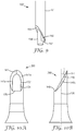
- the pitch (i.e., angle) angle of the primary bevel (e.g., bevel face 140 of FIGS. 5 and 11A and dihedral-shaped primary bevel face 141 of FIG. 10A ) with respect to the central axis 130 is sufficiently acute such that it forms a sharp edge (e.g., for penetrating skin) at the tip 164.
- the pitch of the primary bevel is about 15° to about 40°, relative to the central axis 130.
- the primary bevel has a pitch of about 20° to about 35°, relative to the central axis 130.
- the primary bevel has a pitch of about 25° to about 33°, relative to the central axis 130.
- the tip 164 of the microneedle 260 is located at a point where the first bevel face 140 is farthest from the base 162 relative to the central axis.
- the microneedle 360 of the illustrated embodiment of FIGS. 10A-10B forms the shape of a triple bevel hypodermic needle. That is, it has a primary bevel face 141 with a first pitch (shown in FIG. 10B ) relative to the central axis 130 and it has two secondary bevels 141a and 141b that have a second pitch relative to the primary bevel face 141.
- the second pitch can be about 15° to about 40°, relative to the primary bevel.
- the second pitch can be about 20° to about 30°, relative to the primary bevel.
- the second bevel face 146 is oriented substantially perpendicular to the central axis and intersects the first bevel face along boundary 147 (see FIGS. 6 and 7 ).
- the second bevel face 146 optionally may comprise a portion having a chamfer (i.e., a radius of curvature), as shown in FIG. 7 .
- the microneedle 260 further comprises a hollow channel 170 that extends axially into the body 161 from the tip portion 166 from a bevel opening 172.
- the bevel opening 172 is defined by a first edge 174 of the first bevel face 140 and a second edge 176 of the second bevel face 146.
- the first bevel face 140 forms a surface in the shape of a partial ellipse that substantially surrounds the opening 172.
- FIG. 9 shows a perspective view of one embodiment of a mold part 150', referenced in the Examples as a "first mold section" of the "first mold half', which is used to form the tip portion 166 of the hollow microneedle 260 of FIGS. 4-8 .
- the mold part 150' comprises a base 151.
- cross-sectional shape of the base will match the exterior shape of the tip portion to be formed.
- the base is cylindrical.
- the mold part 150' further comprises a bevel-forming surface 153 and an extension 154'.
- the bevel-forming surface 153 defines the shape and angle of the bevel face of the microneedle.
- the extension 154 defines the shape (e.g., circular) and size of the opening in the bevel face and also defines the shape (e.g., cylindrical) and diameter of the hollow channel in the microneedle.
- the microneedle may comprise a hollow channel that extends only partially through the body of the microneedle (i.e., the hollow channel is a dead-end channel).
- the extension 154' may also define the depth of the hollow channel that is made using the mold part 150.
- an article according to the present disclosure may comprise hollow microneedles having a hollow channel that extends from one side of the article to another (e.g., to a reservoir located on the side opposite the microneedles, not shown).
- the extension 154' of mold part 150' further comprises a protrusion 156 that increases the size of the opening that is created by the mold part 150'.
- the protrusion is truncated at rim 157, which defines the shape and location of the second bevel face formed in a process using the mold part 150'.
- the rim 157 may be oriented substantially perpendicular to the central axis of the microneedle to be formed using the mold part 150'.
- the rim 157 may comprise a radius of curvature.
- the first bevel face of a microneedle defines a plane.
- the plane is a flat plane.
- the plane may be curved or slightly curved.
- the first bevel face may comprise a plurality of nonparallel planes.
- FIGS. 10A and 10 B show one embodiment of a microneedle 360 comprising a primary bevel face 141 comprising a plurality of planes (e.g., planes formed by secondary bevels 141a and 141b, respectively).
- the planes intersect along third edge 142 defining the pitch of the primary bevel that extends from the opening 172 to the tip 164, forming a dihedral primary bevel face 141. Also shown in FIG.
- FIG. 10A are the first edge 174 and second edge 176 that form the opening 172 of the hollow microneedle 360. Also shown in FIG. 10 B is the second bevel face 146, which intersects the planes formed by secondary bevels 141a and 141b of the primary bevel face 141.
- a microneedle of the present disclosure optionally can comprise one or more auxiliary bevels that intersect the first bevel face.
- the auxiliary bevels are used to form a sharper tip for ease of penetration into and through skin tissue.
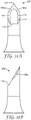
- FIGS. 11A and 11 B show one embodiment of a microneedle 460 comprising a first bevel face 140 and two auxiliary bevels (bevels 180a and 180b) that intersect the first bevel face 140 to form a microneedle tip 164' with a sharp end.
- the auxiliary bevel has a pitch (i.e., an angle in relation to the bevel face 140) of about 15° to about 40°.
- the bevel face 140 has a pitch of about 25° to about 35°. In a more preferred embodiment, the bevel face 140 has a pitch of about 30°3 to about 35°. Also shown in FIG. 11A are the first edge 174 and second edge 176 that form the opening 172 of the hollow microneedle 460. Also shown in FIG. 11 B is the second bevel face 146, which intersects the plane of secondary bevel 141b of the first bevel face 141.
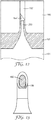
- FIG. 12 shows a schematic view of an apparatus for use in a molding process to make hollow microneedles of the present disclosure.
- a first mold half comprising a mold cavity part 190 and the mold part 150' of FIG. 9 is positioned proximate a second mold half 191, thereby creating a cavity 195 having the shape of the one or more microneedle and the article from which the microneedle projects (see FIG. 1 , for example).
- the mold part 150' comprises the extension 154' that defines the opening and hollow channel proximate the tip of the formed microneedle.
- the second mold half 191 comprises a projection 253 that defines the size and shape of a hollow channel that extends completely through the formed article.
- the microneedles may be formed in such a manner that a hollow channel extending completely through the body of the microneedle may be formed using processes (e.g., laser drilling) subsequent to the molding process.
- the present disclosure provides a method of making an article comprising at least one hollow microneedle that comprises a body having a central axis, a body diameter, a base, a tip portion, and a hollow channel.
- the method comprises providing a first mold half comprising at least one cavity.
- the at least one cavity includes a cavity opening and a cavity surface having a first projection extending therefrom toward the cavity opening.
- the first projection defines a first segment of the hollow channel, the first segment extending into the body of the microneedle from the base.
- the first projection comprises a first longitudinal axis.
- the method further comprises providing a second mold half comprising at least one second projection extending therefrom.
- the at least one second projection defines a tip portion of the at least one microneedle and a second segment of the hollow channel, the second segment extending into the body of the microneedle from a bevel opening proximate the tip of the at least one microneedle.
- the at least one second projection comprises a second longitudinal axis.
- the second projection is shaped and dimensioned to define the tip portion, as described herein.
- the method further comprises contacting at least the first mold half or the second mold half with moldable material (e.g., polymeric material, thermoplastic polymeric material), inserting the at least one second projection into the cavity opening so that the first projection is substantially aligned with the second projection, and forming the article.
- moldable material e.g., polymeric material, thermoplastic polymeric material
- the second projection causes the tip portion of the at least one microneedle to comprise a tip, a first bevel face oriented diagonally with respect to the central axis and extending through about least 75% to about 95% of the body diameter, a second bevel face oriented substantially perpendicular to the central axis and intersecting the first bevel face, a bevel opening defined by a first edge of the first bevel face and a second edge of the second bevel face, and a hollow channel that extends axially into the body from the bevel opening.
- the second projection is inserted into the at least one cavity before contacting at least the first mold half or the second mold half with the moldable material.
- at least the first mold half or the second mold half is contacted with the moldable material before inserting the second projection into the at least one cavity.
- the at least one cavity has a cavity aspect ratio (cavity length to cavity base width) of at least 1.5 to 1.
- the first mold half comprises a plurality of the at least one cavities
- the second mold half comprises a plurality of the at least one second projections, wherein the plurality of second projections is aligned to be inserted simultaneously into the plurality of cavities.
- Microneedle articles that are made according to the present disclosure can have a variety of configurations and features, such as those described in the following patents and patent applications.
- One embodiment for the microneedle articles includes the structures disclosed in U.S. Patent No. 6,312,612 (Sherman et al. ), which describes tapered structures having a hollow central channel.
- Yet still another embodiment for the microneedle array articles includes the structures disclosed in U.S. Patent No. 6,379,324 (Garstein et al. ), which describes hollow microneedles having at least one longitudinal blade at the top surface of the tip of the microneedle.
- a further embodiment for the microneedle array articles includes the structures disclosed in U.S. Patent Application Publication Nos.
- microneedle array articles includes the structures disclosed in U.S. Patent Nos. 6,558,361 (Yeshurun ) and 7,648,484 (Yeshurun et al. ), which both describe hollow microneedle arrays and methods of manufacturing thereof.
- the microneedle material can be (or include) a metal, a ceramic material, or a polymeric material, preferably a medical grade polymeric material.
- the microneedle material can be (or include) silicon or a metal such as stainless steel, titanium, or nickel titanium alloy.
- Exemplary types of medical grade polymeric materials include polycarbonate, liquid crystalline polymer (LCP), polyether ether ketone (PEEK), cyclic olefin copolymer (COC), polybutylene terephthalate (PBT).
- Preferred types of medical grade polymeric materials include polycarbonate and LCP.
- microneedle articles of the present disclosure can be manufactured in any suitable way such as by injection molding, compression molding, metal injection molding, photolithography, stamping, or extrusion.
- hollow microneedle arrays can be made by injection molding of a polymer such as medical grade polycarbonate or LCP, followed by laser drilling to form the channels of the hollow microneedles.
- Nonlimiting examples of molding processes for molding polymeric materials into solid microneedle articles can be found in U.S. Patent No. 8,088,321 (Ferguson et al. ) and U.S. Patent Application Publication Nos. 2012/0258284 (Rendon ) and 2012/0041337 (Ferguson et al. ).
- a non-limiting example of a publication that discloses the formation of hollow channels in articles comprising microneedles is U.S. Provisional Patent Application No. 61/746,198 .
- the microneedle material can be (or include) a biodegradable polymeric material, preferably a medical grade biodegradable polymeric material.
- a biodegradable polymeric material preferably a medical grade biodegradable polymeric material.
- exemplary types of medical grade biodegradable materials include polylactic acid (PLA), polyglycolic acid (PGA), PGA and PLA copolymer, polyester-amide polymer (PEA).
- the hollow microneedles can be a prepared from a dissolvable, degradable, or disintegradable material referred to herein as "dissolvable microneedles".
- a dissolvable, degradable, or disintegradable material is any solid material that dissolves, degrades, or disintegrates during use.
- a "dissolvable microneedle” dissolves, degrades, or disintegrates sufficiently in the tissue underlying the stratum corneum to allow a therapeutic agent to be released into the tissue.
- the therapeutic agent may be coated on or incorporated into a dissolvable microneedle.
- the dissolvable material is selected from a carbohydrate or a sugar.
- the dissolvable material is polyvinyl pyrrolidone (PVP).
- PVP polyvinyl pyrrolidone
- the dissolvable material is selected from the group consisting of hyaluronic acid, carboxymethylcellulose, hydroxypropylmethylcellulose, methylcellulose, polyvinyl alcohol, sucrose, glucose, dextran, trehalose, maltodextrin, and a combination thereof.
- the hollow microneedles can be made from (or include) a combination of two or more of any of the above mentioned materials.
- the tip of a microneedle may be a dissolvable material, while the remainder of the microneedle is a medical grade polymeric material.
- a microneedle or the plurality of hollow microneedles in a microneedle-containing article of the present disclosure can have a variety of shapes that are capable of piercing the stratum corneum.
- one or more of the plurality of microneedles can have a square pyramidal shape, triangular pyramidal shape, stepped pyramidal shape, conical shape, microblade shape, or the shape of a hypodermic needle.
- one or more of the plurality of microneedles can have a square pyramidal shape.
- one or more of the plurality of microneedles can have a triangular pyramidal shape.
- one or more of the plurality of microneedles can have a stepped pyramidal shape.
- one or more of the plurality of microneedles can have a conical shape. In any embodiment, one or more of the plurality of microneedles can have the shape of a hypodermic needle.
- a microneedle array article may comprise an array of microneedles having a combination of any two or more of the foregoing microneedle shapes. The shape of any microneedle in the microneedle array article can be symmetric or asymmetric. The shape of any microneedle in the microneedle array article can be truncated (for example, the plurality of microneedles can have a truncated pyramid shape or truncated cone shape). In a preferred embodiment, each microneedle of the plurality of microneedles in a microneedle array article has a square pyramidal shape.
- each microneedle of the plurality of microneedles in a microneedle array article is a hollow microneedle (that is, the microneedle contains a hollow bore through the microneedle).
- the hollow bore can be from the base of the microneedle to the tip of the microneedle or the bore can be from the base of the microneedle to a position offset from the tip of the microneedle.
- one or more of the plurality of hollow microneedles in a hollow microneedle array can have a conical shape, a cylindrical shape, a square pyramidal shape, a triangular pyramidal shape, or the shape of a hypodermic needle.
- one or more microneedle of the plurality of hollow microneedles in a hollow microneedle array article can have a conical shape; optionally, with a radius of curvature. In any embodiment, one or more microneedle of the plurality of hollow microneedles in a hollow microneedle array article can have a cylindrical shape. In any embodiment, one or more microneedle of the plurality of hollow microneedles in a hollow microneedle array article can have a segment having a square pyramidal shape. In any embodiment, one or more microneedle of the plurality of hollow microneedles in a hollow microneedle array article can have a segment having a triangular pyramidal shape.
- one or more microneedle of the plurality of hollow microneedles in a hollow microneedle array article can have a segment having the shape of a hypodermic needle.
- each microneedle of the plurality of hollow microneedles in a hollow microneedle array article has a segment with the shape of a conventional hypodermic needle.
- an article comprising a hollow microneedle according to the present disclosure may comprise a plurality of the microneedles.
- the plurality of the microneedles optionally may form an array.
- the article can comprise an array of about 3 to about 30, inclusive, of the hollow microneedles of the present disclosure.
- the article can comprise an array of about 8 to about 20, inclusive, of the hollow microneedles of the present disclosure.
- the article can comprise an array of 12, 16, or 18 of the hollow microneedles of the present disclosure.
- the overall height of each microneedle is about 400 ⁇ m to about 3000 ⁇ m. In any embodiment of an article comprising a plurality of hollow microneedles according to the present disclosure, the overall height of each microneedle is about 400 ⁇ m to about 2000 ⁇ m. In any embodiment of an article comprising a plurality of hollow microneedles according to the present disclosure, the overall height of each microneedle is about 750 ⁇ m to about 1600 ⁇ m.
- a hollow channel extending through each of the microneedles has a diameter, proximate the tip of the microneedle, of about 10 ⁇ m to about 200 ⁇ m. In any embodiment of an article comprising a plurality of hollow microneedles according to the present disclosure, a hollow channel extending through each of the microneedles has a diameter, proximate the tip of the microneedle, of about 10 ⁇ m to about 120 ⁇ m.
- a hollow channel extending through each of the microneedles has a diameter, proximate the tip of the microneedle, of about 25 ⁇ m to about 75 ⁇ m.
- a hollow channel extending through each of the microneedles has a cross-sectional area of about 75 ⁇ m 2 to about 32,000 ⁇ m 2 . In any embodiment of an article comprising a plurality of hollow microneedles according to the present disclosure, a hollow channel extending through each of the microneedles has a cross-sectional area of about 75 ⁇ m 2 to about 18,000 ⁇ m 2 . In any embodiment of an article comprising a plurality of hollow microneedles according to the present disclosure, a hollow channel extending through each of the microneedles has a cross-sectional area of about 700 ⁇ m 2 to about 3,000 ⁇ m 2 .
- the hollow microneedle array articles of the present disclosure can be manufactured by injection molding of a polymer such as medical grade polycarbonate or LCP. Typically, these processes use molds to form the substrate with the microneedles extending therefrom.
- a polymer such as medical grade polycarbonate or LCP.
- Microneedles of the present disclosure advantageously provide a larger opening, with respect to a predetermined microneedle wall thickness, than can be attained using conventional process known in the art.
- the larger opening facilitates the delivery of material (e.g., pharmaceutically-active compositions) from the hollow channel of the microneedle into the skin tissue and underlying layers of tissue.
- FIG. 13 shows the area 185 defined by a conventional opening in a hollow microneedle and the additional area 186 that is gained by making a microneedle according to the present disclosure.
- the microscopic mold parts that are used to form the tip portion of the needle are significantly less susceptible to damage during extended use because the extensions that form the tip-proximal hollow channel in the microneedle are made stronger by the presence of the protrusion that forms the second bevel face.
- any of the above embodiments of a microneedle according to the present disclosure can be used for injecting fluid into a body. Any of the above embodiments of a microneedle according to the present disclosure can be used for extracting fluid from a body.
- the microneedle array articles were prepared from polymeric material using standard injection molding procedures.
- the molded microneedle array articles were prepared using a mold assembly prepared from three mold sections with each section machined from steel.
- the first mold section contained projections that defined the beveled shape of the needle tip in the molded article.
- Each projection in the first mold section had a further cylindrical extension that defined features of the tip segment of the microneedles tip, including the opening on a bevel proximate the tip of the microneedle and a portion of the hollow channel extending through the body of each microneedle.
- the second mold section served as a template to define the pattern of the microneedles in the molded article, the external shape and size of the microneedles in the molded article, and the first major surface of the molded article (including the peripheral portion).
- the third mold section contained cylindrical projections emerging from a planar surface with each projection defining a portion of the microneedle hollow channel and the opening located at the base of each microneedle in the molded article.
- the planar surface from which the projections emerged served to define the second major surface of the base segment of the molded article.
- the first and second mold sections were assembled to form a tight fit by inserting the projections of the first mold section into the corresponding openings in the second mold section.
- the assembled first and second mold sections formed the first mold half.
- the third mold section was used as the second mold half.
- the first and second mold halves were installed in a mold base in a 60-ton injection molding press (Sodick Plustech LA 60, Sodick Plustech Co., Yokohama, Japan).
- the parting line of the mold assembly had both primary and secondary vents for general air evacuation during injection of the polymeric material.
- Vectra MT1300 liquid crystal polymer (LCP) pellets (Ticona Engineering Polymers, Florence, KY) were loaded into a reciprocating screw and heated until molten.
- the first mold half and second mold half were heated to a temperature (hereafter referred to as the "mold temperature at injection") of 200 °F (93.3 °C).
- the molding cycle was initiated by closing the first mold half with the second mold half.
- the molds were clamped together with approximately 20 to 60 tons of force. In the clamped position, the projections of the second mold half did not contact any surface of the first mold half.
- a first portion (approx. 50-95% of the part size volume) of the total amount of material from the reciprocating screw was injected into the mold chamber at a fixed velocity (hereafter referred to as the "injection velocity") of 7 inches/second (17.8 cm/second).
- the process was switched from an injection-driven to a pressure-driven mode by applying a fixed pressure (hereafter referred to as the "pack pressure") of 13,500 psi (93,079 kilopascal) to force the remainder of the molten material into the negative mold insert.
- the pack pressure was applied for a fixed time (hereafter referred to as the "hold time") of 5 seconds.
- the pack pressure was subsequently released and the mold chamber was cooled to an ejection temperature set below the softening temperature of LCP.
- the mold chamber was opened and the microneedle array article was ejected.
- Example 2 Injection apparatus used to test the microneedle articles
- the adhesive assembly used was a laminate composed of only two layers.
- the first layer was a 0.10 mm thick sheet of 3M 1510 double sided tape (available from the 3M Company).
- the second layer was a 0.07 mm sheet of 3M 1524 transfer adhesive.
- the two layer adhesive assembly was positioned to cover the first major surface of base member of the lower housing at the rounded end section of the device.
- the adhesive assembly laminate was laser cut so that the size and shape of the adhesive assembly was matched to that of the device.
- the two layers of the adhesive assembly each contained cut-out regions that were aligned to each other and exactly matched the opening in the device housing.
- the device and adhesive assembly were oriented so that the first layer of the adhesive assembly was adhered to the lower housing of the device.
- the adhesive assembly was aligned with the device so that the opening in the first layer of the adhesive assembly was coincident with the opening in the device.
- a release liner was used during storage of the device to protect the exposed adhesive of the fourth layer of the adhesive assembly.
- the hollow microneedle array article (as shown in FIG. 1 ) used in the injection apparatus was injection molded (as described in Example 1) from Vectra MT1300 liquid crystal polymer (LCP) in the shape of a square approximately 1.6 cm 2 in area.
- the article featured 12 hollow microneedles centered on the article and arranged along the perimeter of a square pattern.
- the microneedles extended from the first major surface of the article.
- the microneedles were evenly spaced with 4 microneedles defining each side of the square.
- the peripheral portion surrounding the square microneedle pattern canted away from the perimeter of the pattern with an 18 degree slope.
- the spacing between neighboring microneedles was about 2 mm (as measured from tip to tip).
- the microneedles were oriented so that the openings in the tip segments were all aligned and facing toward one side of the square pattern.
- the external diameter of each microneedle at the base was about 2 mm.
- the flared base segment of each microneedle had a radius of curvature of about 0.7 mm.
- Each microneedle was in the shape of a triple bevel hypodermic needle (33.6 degree bevel with a split bevel of 20 degrees).
- the tip segment of each microneedle was shaped as shown in FIG. 10A .
- Each microneedle had a total height of about 1500 microns as measured from the base to the tip.
- the distance from the tip of each microneedle to the center of the opening near the tip was about 400 microns.
- the average diameter of the hollow channel created by molding was about 100 microns.
- a section of material (about 50 microns) was removed using a laser drilling procedure (femtosecond) described in U.S. Provisional Patent Application No. 61/746,198 .
- the diameter of the hollow channel of each microneedle in the laser drilled region was about 70 microns.
- Example 2 The same microneedle injection apparatus as described in Example 2 was used with the exception that the wire diameter of the U-shaped leaf-like insertion spring (i.e. first stored energy device as described in U.S. Patent Application Publication No. US2012/0123387 ( FIGS. 1-13 ) and U.S. Provisional Patent Application No. 61/740,941 ( FIGS. 2, 14 and 15 ) was 1.40 mm instead of 1.50 mm.
- the wire diameter of the U-shaped leaf-like insertion spring i.e. first stored energy device as described in U.S. Patent Application Publication No. US2012/0123387 ( FIGS. 1-13 ) and U.S. Provisional Patent Application No. 61/740,941 ( FIGS. 2, 14 and 15 ) was 1.40 mm instead of 1.50 mm.
- Example 2 The same microneedle injection apparatus as described in Example 2 was constructed with the exception that a different hollow microneedle array article was used.
- the hollow microneedle article was injection molded (as described in Example 1) from Vectra MT1300 liquid crystal polymer (LCP) in the shape of a square approximately 1.6 cm 2 in area.
- the microneedles extended from the first major surface of the article.
- the article featured 16 hollow microneedles evenly spaced and defining a 4 by 4 square pattern centered on the article.
- the peripheral portion surrounding the square microneedle pattern was canted away from the perimeter of the central portion with an 18 degree slope relative to a plane formed by the central portion.
- the spacing between neighboring microneedles was about 2 mm (as measured from tip to tip).
- the microneedles were oriented so that the openings in the tip segments were all aligned and facing toward one side of the square pattern.
- the external diameter of each microneedle at the base was about 2 mm.
- the flared base segment of each microneedle had a radius of curvature of about 0.7 mm.
- Each microneedle was in the shape of a triple bevel hypodermic needle (33.6 degree bevel with a split bevel of 20 degrees).
- the tip segment of each microneedle was shaped as shown in FIG. 10A .
- Each microneedle had a total height of about 1500 microns as measured from the base to the tip.
- the distance from the tip of each microneedle to the center of the opening near the tip was about 400 microns.
- the average diameter of the hollow channel created by molding was about 100 microns.
- a section of material (about 50 microns) was removed using a laser drilling procedure (femtosecond) described in U.S. Provisional Patent Application No. 61/746,198 .
- the diameter of the hollow channel of each microneedle in the laser drilled region was about 70 microns.
- Example 5 Use of microneedle article to inject a substance
- the injection apparatus of Example 3 was used.
- the release liner was removed from the adhesive assembly and the apparatus was adhered to the skin of the pig.
- the skin at the application site was gently stretched to provide a slight tension to the skin.
- the skin was then allowed to relax and the push-button was depressed to cause release of the applicator element and insertion of the microneedle array article into the skin of the pig.
- Removal of the tapered pin from the housing released the coiled spring which initiated the injection of the methylene blue solution into the pig.
- the apparatus was maintained on the skin for one additional minute.
- the apparatus was removed from the skin and the skin surface was examined to determine if there was any methylene blue solution on the surface of the skin.
- the presence of methylene blue solution on the skin was an indication that not all of the methylene blue was injected into the animal.
- the injection site was wiped with a pre-tared absorbent wipe and the wipe was then weighed to determine the amount of methylene blue that was not successfully delivered.
- DOP depth of penetration
- the microneedles on the article were coated using a three step process.
- the first two steps involved applying primer coatings to the microneedles and the third step involved applying a thin coating of Rhodamine B to the microneedles.
- Step 1 the array articles were flood coated with a 35 microliter solution containing 0.5 mg/mL polyvinyl alcohol (80% hydrolyzed) (Sigma-Aldrich, Inc., St. Louis, MO) and 35 ⁇ g/ml of TWEEN® 80 (Sigma-Aldrich) in 90% (w/v) ethanol. The coated articles were then dried at 35 °C for 20 minutes.
- polyvinyl alcohol 80% hydrolyzed
- TWEEN® 80 Sigma-Aldrich
- Step 2 the articles from Step 1 were flood coated with 35 microliters of an aqueous solution of 33.3 mg/ml aluminum potassium sulfate (Penta Manufacturing, Livingston, NJ). The coated articles were then dried at 35 °C for 30 minutes.
- Step 3 the primed articles from Step 2 were flood coated with 40 microliters of an aqueous solution of 0.08% (w/v) Rhodamine B (Sigma-Aldrich). The coated articles were dried at 35 °C for 30 minutes.
- the three step process provided articles in which the microneedles were completely covered with a thin, opaque coating of Rhodamine B.
- the ham region was selected as the application site for microneedle insertion.
- the application site was first trimmed with an electric clipper and then shaved using a razor and shaving cream.
- the shaved area was scrubbed using soapy water and a BUF-PUF exfoliation sponge (3M Company) and then rinsed with deionized water.
- the animal was placed in a lateral recumbent position on a heated table (38 °C).
- the animal was anesthetized with isofluorene gas and maintained under anesthesia throughout the experiment.
- the application site was then wiped with a 70% isopropanol in water solution.
- Example 4 The injection apparatus described in Example 4 with a Rhodamine B coated article was applied to the pig skin.
- the push-button was depressed to cause release the applicator element and insertion of the microneedles of the microneedle array into the skin of the pig.
- the applicator was maintained on the skin for an additional 5 minutes.
- the applicator was removed from the animal.
- Example 8 Use of microneedle article to inject a substance
- the apparatus and hollow microneedle array article described in Example 2 was used with the exception that the drug cartridge was filled with the 5% dextrose USP injection solution instead of the methylene blue solution.
- the release liner was removed from the adhesive assembly and the apparatus was adhered to the thigh region of the subject.
- the push button was depressed to insert the microneedles into the skin of the subject.
- the tapered pin was removed from the housing to release the coiled spring and begin the injection of the dextrose solution into the subject.
- the timer was started at the time of pin removal and stopped when the plunger was observed to reach the end of travel in the cartridge.
- the apparatus was removed from the subject and the skin surface around the application site was swabbed with a dry swab.
- the mass of the swab was measured immediately before and immediately after swabbing.
- the amount of residual fluid on the skin surface was determined by calculating the difference in the swab measurements. No attempt was made to differentiate between the different types of fluid (such as blood, interstitial fluid, or dextrose solution) found on the skin surface.
- the results are presented in Tables 3 and 4.
- Table 3 Injection Time Male Subjects Female Subjects Minimum Injection Time (sec) 27 17 Maximum Injection Time (sec) 332 228 Mean Injection Time (sec) 110 67 Standard Deviation (sec) 86 57
- Table 4 Fluid Recovery Male Subjects Female Subjects Minimum Amount of Fluid at Site 0 mg 0 mg Maximum Amount of Fluid at Site 4 mg 20 mg Mean Amount of Fluid at Site 2 mg 2 mg Standard Deviation 3 mg 4 mg
Description
- This application claims priority to
U.S. Provisional Patent Application No. 61/846,934, filed July 16, 2013 - Transdermal and topical drug delivery can be used for therapeutic treatment, but the number of molecules that can be effectively delivered using these routes can be limited by the barrier properties of skin. The main barrier to transport of molecules through the skin is the stratum corneum (the outermost layer of the skin).
- A number of different skin treatment methods have been proposed in order to increase the permeability or porosity of the outermost skin layers, such as the stratum corneum, thus enhancing drug delivery through or into those layers. The stratum corneum is a complex structure of compact keratinized cell remnants separated by lipid domains. The stratum corneum is formed of keratinocytes, which comprise the majority of epidermal cells that lose their nuclei and become corneocytes. These dead cells comprise the stratum corneum, which has a thickness of only about 10-30 microns and protects the body from invasion by exogenous substances and the outward migration of endogenous fluids and dissolved molecules. Various skin treatment methods include the use of microneedles, laser ablation, RF ablation, heat ablation, sonophoresis, iontophoresis, or a combination thereof.
- Devices including arrays of relatively small structures, sometimes referred to as microneedles or micro-pins, have been disclosed for use in connection with the delivery of therapeutic agents and other substances through the skin and other surfaces. The devices are typically pressed against the skin in an effort to pierce the stratum corneum such that the therapeutic agents and other substances can sequentially or simultaneously pass through that layer and into the tissues below. Microneedles of these devices pierce the stratum corneum upon contact, making a plurality of microscopic slits which serve as passageways through which molecules of active components can be delivered into the body. In delivering an active component, the microneedle device can be provided with a reservoir for temporarily retaining an active component in liquid form prior to delivering the active component through the stratum corneum. In some constructions, the microneedles can be hollow to provide a liquid flow path directly from the reservoir and through the microneedles to enable delivery of the therapeutic substance through the skin. In alternate constructions, active component(s) may be coated on the microneedle array and delivered directly through the skin after the stratum corneum has been punctured.
- Microneedle arrays can be used in conjunction with an applicator device capable of being used several times or as a single-use device. The microneedle arrays are generally used once and then discarded.
-
DE 10 2008 052749 A1 refers to a needle having a piercing end including the shape of an angular truncated cylinder or frustum with a cutting force reducing section. The section protrudes from the frustum at a front end, or protrudes outwardly from an outer circumferential line of the frustum. -
US 2006/202385 A1 describes a master mould which is made by wire cutting a plate in two or more directions to provide a base with an array of master mould needles protruding therefrom. The size and shape of the master mould needles can readily be varied by varying the angles of upward and downward cuts in the two or more directions. -
EP 2 062 611 A1 describes a micro-needle which includes first and second end sections arranged in a longitudinal direction and is made of a biocompatible and biodegradable material including chitin and/or chitosan. -
CN 101 244 303 B discloses a miniature solid or hollow silicon needle, a silicon needle array and the manufacture method, belonging to the medical service and hairdressing apparatus and micro machining technical field. -
US 2005/065463 A1 discloses an applicator for applying functional substances, such as cosmetic powder, food color marking, India ink effect marks, or drugs into human skin, having a base, a plurality of microneedles fixed to and projecting from the base a distance only sufficient to penetrate into the stratum corneum or dermis. - The present invention is defined by the features of the independent claims. Further preferred embodiments of the present invention are defined in the dependent claims. In particular, it is now known that the configuration of the tip portion of a hollow microneedle can result in more consistent and effective administration of a composition (e.g., a pharmaceutically-active composition) into skin tissue. Now, it is also known that the configuration of the present disclosure also results in a more robust manufacturing process to make articles with hollow microneedles.
- The present disclosure generally relates to articles that comprise at least one hollow microneedle. In particular, the present disclosure relates to the tip portion of the hollow microneedle and the configuration of a bevel and an opening in the bevel proximate the tip of the microneedle
- Some aspects of the present disclosure provide an article. The article can comprise at least one microneedle. The at least one microneedle can comprise a base, an elongated body having a central axis and a body diameter, a tip portion, and a hollow channel. The tip portion comprises a tip, a first bevel face oriented diagonally with respect to the central axis and extending through about 75% to about 95% of the body diameter, a second bevel face oriented substantially perpendicular to the central axis and intersecting the first bevel face, and a bevel opening defined by a first edge of the first bevel face and a second edge of the second bevel face. The hollow channel extends axially into the body from the bevel opening. The second bevel face extends through no more than about 25% of the body diameter.
- Other aspects of the present disclosure provide a method of making an article comprising at least one hollow microneedle. The hollow microneedle comprises a body having a central axis, a body diameter, a base, a tip portion, and a hollow channel. The method can comprise providing a first mold half comprising at least one cavity, wherein the at least one cavity includes a cavity opening and a cavity surface having a first projection extending therefrom toward the cavity opening, wherein the first projection defines a first segment of the hollow channel, the first segment extending into the body of the microneedle from the base, wherein the first projection comprises a first longitudinal axis. The method further can comprise providing a second mold half comprising at least one second projection extending therefrom; wherein the at least one second projection defines a tip portion of the at least one microneedle and a second segment of the hollow channel, the second segment extending into the body of the microneedle from a bevel opening proximate the tip of the at least one microneedle; wherein the at least one second projection comprises a second longitudinal axis; wherein the second projection is shaped and dimensioned to define the tip portion. The method further can comprise contacting at least the first mold half or the second mold half with moldable material, inserting the at least one second projection into the cavity opening so that the first projection is substantially aligned with the second projection, and forming the article. The second projection causes formation of the tip portion of the at least one microneedle to comprise a tip, a first bevel face oriented diagonally with respect to the central axis and extending through about 75% to about 95% of the body diameter, a second bevel face oriented substantially perpendicular to the central axis and intersecting the first bevel face, a bevel opening defined by a first edge of the first bevel face and a second edge of the second bevel face, and a hollow channel that extends axially into the body from the bevel opening. The second projection causes formation of the tip portion of the at least one microneedle such that the second bevel face extends through no more than about 25% of the body diameter.
- The phrase "injection apparatus" refers to an integrated device capable of delivering or extracting a fluid over a certain period and is not limited to devices intended solely for an infusion. Accordingly, an injection apparatus may be used, for example, for injecting fluid into the dermis or extracting fluid from tissue.
- The term "transdermally" and variations thereof, is generally used to refer to any type of delivery of an active ingredient that crosses any portion of skin. That is, transdermally can generally include systemic delivery (i.e., where the active ingredient is transported across, or substantially through, the dermis such that the active ingredient is delivered into the bloodstream), as well as intradermal delivery (i.e., where the active ingredient is transported partially through the dermis, e.g., across the outer layer (stratum corneum) of the skin, where the active ingredient is delivered into the skin, e.g., for treating psoriasis or for local anesthetic delivery). That is, transdermal delivery as used herein includes delivery of an active ingredient that is transported across at least a portion of skin (but not necessarily all of the layers of skin), rather than merely being topically applied to an outer layer of the skin.
- The phrase "hollow microneedle" refers to a specific microscopic structure that is designed for piercing the stratum corneum to facilitate the delivery of drugs through the skin. By way of example, microneedles can include needle or needle-like structures, as well as other structures capable of piercing the stratum corneum and delivering liquid drug formulations to skin or tissue layers beneath the stratum corneum.
- The words "preferred" and "preferably" refer to embodiments of the invention that may afford certain benefits, under certain circumstances. However, other embodiments may also be preferred, under the same or other circumstances. Furthermore, the recitation of one or more preferred embodiments does not imply that other embodiments are not useful, and is not intended to exclude other embodiments from the scope of the invention.
- The terms "comprises" and variations thereof do not have a limiting meaning where these terms appear in the description and claims.
- As used herein, "a," "an," "the," "at least one," and "one or more" are used interchangeably. Thus, for example, a microneedle can be interpreted to mean "one or more" microneedles.
- The term "and/or" means one or all of the listed elements or a combination of any two or more of the listed elements.
- Also herein, the recitations of numerical ranges by endpoints include all numbers subsumed within that range (e.g., 1 to 5 includes 1, 1.5, 2, 2.75, 3, 3.80, 4, 5, etc.).
- The above summary of the present invention is not intended to describe each disclosed embodiment or every implementation of the present invention. The description that follows more particularly exemplifies illustrative embodiments. In several places throughout the application, guidance is provided through lists of examples, which examples can be used in various combinations. In each instance, the recited list serves only as a representative group and should not be interpreted as an exclusive list.
- Additional details of these and other embodiments are set forth in the accompanying drawings and the description below. Other features, objects and advantages will become apparent from the description and drawings, and from the claims.
- The present invention will be further explained with reference to the drawing figures listed below, where like structure is referenced by like numerals throughout the several views.
-
FIG. 1 is a perspective view of an embodiment of an article comprising a hollow microneedle. -
FIG. 2 is a perspective view of an embodiment of a hollow microneedle comprising a bevel face having an opening. -
FIG. 3 is a perspective view of a mold part used to form a tip portion of the hollow microneedle ofFIG. 2 . -
FIG. 4 is a perspective view of one embodiment of hollow microneedle having a bevel face with an opening according to the present disclosure. -
FIG. 5 is a side view of the hollow microneedle ofFIG. 4 , showing the bevel face and the opening. -
FIG. 6 is a side view of the hollow microneedle ofFIG. 4 . -
FIG. 7 is a cross-sectional view of the hollow microneedle ofFIG. 5 taken along line 7-7. -
FIG. 8 is a top view of the hollow microneedle ofFIG. 4 . -
FIG. 9 is a perspective view of a mold part used to form a tip portion of the hollow microneedle ofFIG. 4 . -
FIG. 10A is a side view, showing the bevel face and bevel opening, of another embodiment of a hollow microneedle according to the present disclosure. -
FIG. 10B is a side view of the hollow microneedle ofFIG. 10A , showing one plane of the bevel face. -
FIG. 11A is a side view, showing the bevel face and bevel opening, of yet another embodiment of a hollow microneedle according to the present disclosure. -
FIG. 11B is a side view of the hollow microneedle ofFIG. 11A , showing one of the secondary bevels that forms the tip of the microneedle. -
FIG. 12 is a schematic view of one embodiment of portions of mold parts that are used in a molding process to make an article with a hollow microneedle according to the present disclosure. -
FIG. 13 is a duplication ofFIG. 5 , contrasting the area of a bevel opening in a traditional needle tip and the area of the bevel opening in a microneedle according to the present disclosure. - Before any embodiments of the present disclosure are explained in detail, it is to be understood that the invention is not limited in its application to the details of construction and the arrangement of components set forth in the following description or illustrated in the following drawings. The invention is capable of other embodiments and of being practiced or of being carried out in various ways. Also, it is to be understood that the phraseology and terminology used herein is for the purpose of description and should not be regarded as limiting. The use of "including," "comprising," or "having" and variations thereof herein is meant to encompass the items listed thereafter and equivalents thereof as well as additional items. Unless specified or limited otherwise, the terms "mounted," "connected," "supported," and "coupled" and variations thereof are used broadly and encompass both direct and indirect mountings, connections, supports, and couplings. It is to be understood that other embodiments may be utilized, and structural or logical changes may be made without departing from the scope of the present disclosure. Furthermore, terms such as "front," "rear," "top," "bottom," and the like are only used to describe elements as they relate to one another, but are in no way meant to recite specific orientations of the apparatus, to indicate or imply necessary or required orientations of the apparatus, to indicate or imply necessary or required orientations of the apparatus, or to specify how the invention described herein will be used, mounted, displayed, or positioned in use.
- The present disclosure generally relates to articles comprising hollow microneedles having a tip portion that penetrates skin and provides an opening through which a composition (e.g., a pharmaceutically-active compound) can be delivered into the skin tissue and other tissue disposed in or underlying the skin tissue. In particular, the present disclosure relates to certain aspects of the tip portion that can provide more-efficient delivery of compositions into the skin tissue. In addition, the aspects generally provide a more-robust method of manufacturing hollow microneedles and particularly provide a more-robust method of manufacturing high-aspect-ratio hollow microneedles.
- Articles comprising hollow microneedles and/or hollow microneedle arrays are used, for example, to deliver compositions (e.g., compositions comprising active ingredients). Such articles are described, for example, in
U.S. Patent Nos. 8,088,321 and8,246,893 ; and U.S. Patent Application Publication Nos.US2011/0213335 ,US2012/0123387 ,US2012/0041337 ; and International Patent Publication No.WO2012/074576 . - Turning to the drawings,
FIG. 1 shows one embodiment of anarticle 100 comprising at least onemicroneedle 160. In the illustrated embodiment, thearticle 100 comprises a square-shaped array of a plurality ofmicroneedles 160. Thearticle 100 comprises aunitary substrate 110 having afirst side 112 from which themicroneedles 160 extend. In any embodiment, an article according to the present disclosure can comprise a plurality of hollow microneedles. In any embodiment, the hollow microneedles can be arranged in an array (e.g., a regular array). Non-limiting examples of articles comprising hollow microneedles are described inU.S. Provisional Patent Nos. 61/846,909 61/846,905 filed on July 16, 2013 -
FIG. 2 shows one embodiment of ahollow microneedle 160. Themicroneedle 160 comprises anelongated body 161 having at least onemajor surface 163,central axis 130, abody diameter 168, a base 162 at one end of thebody 161, and atip portion 166 at the other end of thebody 161. Thebody 161 can take the form of a variety of shapes including, but not limited to, cylindrical, conical, crateriform, pyramidal, and combinations thereof. Thetip portion 166 comprises abevel face 140 that extends diagonally, relative to the central axis, through thebody 161 and thereby forming thetip 164. As used herein, the "tip" of a microneedle is a point of the microneedle that is farthest (as measured along the central axis) from the base of the microneedle. Preferably, the angle of thebevel face 140 with respect to thecentral axis 130 is sufficiently acute such that it forms a sharp edge (e.g., for penetrating skin) at thetip 164. Themicroneedle 160 further comprises ahollow channel 170 that extends from thetip portion 166 into thebody 161 via abevel opening 172 on thebevel face 140. Although illustrated as a relatively flat plane that is not coplanar with the at least one major surface of the microneedle, it is contemplated that, in any embodiment, the bevel face in which the bevel opening is disposed may be coplanar with the at least one major surface of the microneedle (not shown). -
FIG. 3 shows a perspective view of one embodiment of amold part 150, referenced in the Examples as a "first mold section of the "first mold half', which is used to form thetip portion 166 of thehollow microneedle 160 ofFIG. 2 . Themold part 150 comprises abase 151. In the illustrated embodiment ofFIG. 3 , the base is cylindrical. The mold part further comprises a bevel-formingsurface 153 and anextension 154. The bevel-formingsurface 153 defines the shape and angle of the bevel face of the microneedle. Theextension 154 defines the shape (e.g., circular) and size of the opening in the bevel face and also defines the shape (e.g., cylindrical) and diameter of the hollow channel in the microneedle. In any embodiment, the microneedle may comprise a hollow channel that extends only partially through the body of the microneedle (i.e., the hollow channel is a dead-end channel). In these embodiments, theextension 154 may also define the depth of the hollow channel that is made using themold part 150. -
FIGS. 4-8 show various views of one embodiment of a microneedle 260 according to the present disclosure. Similar to themicroneedle 160 shown inFIG. 2 , themicroneedle 260 comprises anelongated body 161 having at least onemajor surface 163,central axis 130, abody diameter 168, a base 162 at one end of thebody 161, and atip portion 166 at the other end of thebody 161. Thebody 161 can take the form of a variety of shapes including, but not limited to, cylindrical, conical, crateriform, pyramidal, and combinations thereof. - In contrast to the
microneedle 160 ofFIG. 2 , thetip portion 166 of themicroneedle 260 comprises afirst bevel face 140 and asecond bevel face 146. Thefirst bevel face 140 is oriented diagonally with respect to thecentral axis 130 and extends through at least about 75% of the body diameter, the body diameter being measured along a plane that is perpendicular to the central axis at the point where the first bevel face is closest the base 162 relative to the central axis 130 (i.e., the body diameter at the second bevel face 146). In any embodiment, the first bevel face extends through about 75% to about 95% of the body diameter, the body diameter being measured along a plane that is perpendicular to the central axis at the point where the first bevel face is closest the base 162 relative to thecentral axis 130. In any embodiment, the first bevel face extends through at least about 80% of the body diameter, the body diameter being measured along a plane that is perpendicular to the central axis at the point where the first bevel face is closest the base 162 relative to thecentral axis 130. In any embodiment, the first bevel face extends through at least about 85% of the body diameter, the body diameter being measured along a plane that is perpendicular to the central axis at the point where the first bevel face is closest the base 162 relative to thecentral axis 130. In any embodiment, the first bevel face extends through at least about 90% of the body diameter, the body diameter being measured along a plane that is perpendicular to the central axis at the point where the first bevel face is closest the base 162 relative to thecentral axis 130. In any embodiment, the first bevel face extends through not more than about 95% of the body diameter, the body diameter being measured along a plane that is perpendicular to the central axis at the point where the first bevel face is closest the base 162 relative to thecentral axis 130. In any embodiment, the first bevel face extends through at least about 80% to about 95% of the body diameter, the body diameter being measured along a plane that is perpendicular to the central axis at the point where the first bevel face is closest the base 162 relative to thecentral axis 130. - Thus, in any embodiment, the
second bevel face 146 extends through about 5% to about 25% of the body diameter of the microneedle. - Preferably, the pitch (i.e., angle) angle of the primary bevel (e.g.,
bevel face 140 ofFIGS. 5 and11A and dihedral-shapedprimary bevel face 141 ofFIG. 10A ) with respect to thecentral axis 130 is sufficiently acute such that it forms a sharp edge (e.g., for penetrating skin) at thetip 164. In any embodiment, the pitch of the primary bevel is about 15° to about 40°, relative to thecentral axis 130. In a preferred embodiment, the primary bevel has a pitch of about 20° to about 35°, relative to thecentral axis 130. In a more preferred embodiment, the primary bevel has a pitch of about 25° to about 33°, relative to thecentral axis 130. In the illustrated embodiment ofFIGS. 4-8 , thetip 164 of themicroneedle 260 is located at a point where thefirst bevel face 140 is farthest from the base 162 relative to the central axis. - The
microneedle 360 of the illustrated embodiment ofFIGS. 10A-10B forms the shape of a triple bevel hypodermic needle. That is, it has aprimary bevel face 141 with a first pitch (shown inFIG. 10B ) relative to thecentral axis 130 and it has twosecondary bevels primary bevel face 141. In any embodiment, the second pitch can be about 15° to about 40°, relative to the primary bevel. In any embodiment, the second pitch can be about 20° to about 30°, relative to the primary bevel. - The
second bevel face 146 is oriented substantially perpendicular to the central axis and intersects the first bevel face along boundary 147 (seeFIGS. 6 and 7 ). In any embodiment, thesecond bevel face 146 optionally may comprise a portion having a chamfer (i.e., a radius of curvature), as shown inFIG. 7 . - The
microneedle 260 further comprises ahollow channel 170 that extends axially into thebody 161 from thetip portion 166 from abevel opening 172. Thebevel opening 172 is defined by afirst edge 174 of thefirst bevel face 140 and asecond edge 176 of thesecond bevel face 146. As shown inFIG. 5 , thefirst bevel face 140 forms a surface in the shape of a partial ellipse that substantially surrounds theopening 172. -
FIG. 9 shows a perspective view of one embodiment of a mold part 150', referenced in the Examples as a "first mold section" of the "first mold half', which is used to form thetip portion 166 of thehollow microneedle 260 ofFIGS. 4-8 . The mold part 150' comprises abase 151. Generally, cross-sectional shape of the base will match the exterior shape of the tip portion to be formed. In the illustrated embodiment ofFIG. 9 , the base is cylindrical. - The mold part 150'further comprises a bevel-forming
surface 153 and an extension 154'. The bevel-formingsurface 153 defines the shape and angle of the bevel face of the microneedle. Theextension 154 defines the shape (e.g., circular) and size of the opening in the bevel face and also defines the shape (e.g., cylindrical) and diameter of the hollow channel in the microneedle. In any embodiment, the microneedle may comprise a hollow channel that extends only partially through the body of the microneedle (i.e., the hollow channel is a dead-end channel). In these embodiments, the extension 154' may also define the depth of the hollow channel that is made using themold part 150. In any embodiment, an article according to the present disclosure may comprise hollow microneedles having a hollow channel that extends from one side of the article to another (e.g., to a reservoir located on the side opposite the microneedles, not shown). - In contrast to the
mold part 150 ofFIG. 3 , the extension 154' of mold part 150' further comprises aprotrusion 156 that increases the size of the opening that is created by themold part 150'.The protrusion is truncated atrim 157, which defines the shape and location of the second bevel face formed in a process using the mold part 150'. In any embodiment, therim 157 may be oriented substantially perpendicular to the central axis of the microneedle to be formed using the mold part 150'. In any embodiment, therim 157 may comprise a radius of curvature. - In any embodiment, the first bevel face of a microneedle according to the present disclosure defines a plane. In any embodiment, the plane is a flat plane. In any embodiment, the plane may be curved or slightly curved. In any embodiment, the first bevel face may comprise a plurality of nonparallel planes.
FIGS. 10A and 10 B show one embodiment of a microneedle 360 comprising aprimary bevel face 141 comprising a plurality of planes (e.g., planes formed bysecondary bevels third edge 142 defining the pitch of the primary bevel that extends from theopening 172 to thetip 164, forming a dihedralprimary bevel face 141. Also shown inFIG. 10A are thefirst edge 174 andsecond edge 176 that form theopening 172 of thehollow microneedle 360. Also shown inFIG. 10 B is thesecond bevel face 146, which intersects the planes formed bysecondary bevels primary bevel face 141. - In any embodiment, a microneedle of the present disclosure optionally can comprise one or more auxiliary bevels that intersect the first bevel face. Typically, the auxiliary bevels are used to form a sharper tip for ease of penetration into and through skin tissue.
FIGS. 11A and 11 B show one embodiment of a microneedle 460 comprising afirst bevel face 140 and two auxiliary bevels (bevels first bevel face 140 to form a microneedle tip 164' with a sharp end. In any embodiment, the auxiliary bevel has a pitch (i.e., an angle in relation to the bevel face 140) of about 15° to about 40°. In a preferred embodiment, thebevel face 140 has a pitch of about 25° to about 35°. In a more preferred embodiment, thebevel face 140 has a pitch of about 30°3 to about 35°. Also shown inFIG. 11A are thefirst edge 174 andsecond edge 176 that form theopening 172 of thehollow microneedle 460. Also shown inFIG. 11 B is thesecond bevel face 146, which intersects the plane ofsecondary bevel 141b of thefirst bevel face 141. - Hollow microneedles of the present disclosure can be made using molding processes that are known in the art.
U.S. Provisional Patent Application No. 61/740,941 FIG. 12 shows a schematic view of an apparatus for use in a molding process to make hollow microneedles of the present disclosure. As described in the Examples herein, a first mold half comprising amold cavity part 190 and the mold part 150' ofFIG. 9 is positioned proximate asecond mold half 191, thereby creating acavity 195 having the shape of the one or more microneedle and the article from which the microneedle projects (seeFIG. 1 , for example). The mold part 150' comprises the extension 154' that defines the opening and hollow channel proximate the tip of the formed microneedle. Optionally, thesecond mold half 191 comprises aprojection 253 that defines the size and shape of a hollow channel that extends completely through the formed article. As described inU.S. Provisional Patent Application No. 61/740,941 - In another aspect, the present disclosure provides a method of making an article comprising at least one hollow microneedle that comprises a body having a central axis, a body diameter, a base, a tip portion, and a hollow channel. The method comprises providing a first mold half comprising at least one cavity. The at least one cavity includes a cavity opening and a cavity surface having a first projection extending therefrom toward the cavity opening. The first projection defines a first segment of the hollow channel, the first segment extending into the body of the microneedle from the base. The first projection comprises a first longitudinal axis. The method further comprises providing a second mold half comprising at least one second projection extending therefrom. The at least one second projection defines a tip portion of the at least one microneedle and a second segment of the hollow channel, the second segment extending into the body of the microneedle from a bevel opening proximate the tip of the at least one microneedle. The at least one second projection comprises a second longitudinal axis. The second projection is shaped and dimensioned to define the tip portion, as described herein. The method further comprises contacting at least the first mold half or the second mold half with moldable material (e.g., polymeric material, thermoplastic polymeric material), inserting the at least one second projection into the cavity opening so that the first projection is substantially aligned with the second projection, and forming the article. In any embodiment, after forming the article, the second projection causes the tip portion of the at least one microneedle to comprise a tip, a first bevel face oriented diagonally with respect to the central axis and extending through about least 75% to about 95% of the body diameter, a second bevel face oriented substantially perpendicular to the central axis and intersecting the first bevel face, a bevel opening defined by a first edge of the first bevel face and a second edge of the second bevel face, and a hollow channel that extends axially into the body from the bevel opening. In any embodiment, the second projection is inserted into the at least one cavity before contacting at least the first mold half or the second mold half with the moldable material. Alternatively, in any embodiment, at least the first mold half or the second mold half is contacted with the moldable material before inserting the second projection into the at least one cavity.
- In any of the above embodiments of the method, the at least one cavity has a cavity aspect ratio (cavity length to cavity base width) of at least 1.5 to 1. In any of the above embodiments of the method, the first mold half comprises a plurality of the at least one cavities, wherein the second mold half comprises a plurality of the at least one second projections, wherein the plurality of second projections is aligned to be inserted simultaneously into the plurality of cavities.
- Microneedle articles that are made according to the present disclosure can have a variety of configurations and features, such as those described in the following patents and patent applications. One embodiment for the microneedle articles includes the structures disclosed in
U.S. Patent No. 6,312,612 (Sherman et al. ), which describes tapered structures having a hollow central channel. Yet still another embodiment for the microneedle array articles includes the structures disclosed inU.S. Patent No. 6,379,324 (Garstein et al. ), which describes hollow microneedles having at least one longitudinal blade at the top surface of the tip of the microneedle. A further embodiment for the microneedle array articles includes the structures disclosed in U.S. Patent Application Publication Nos.US2012/0123387(Gonzalez et al. ) andUS2011/0213335 (Burton et al. ), which both describe hollow microneedles. A still further embodiment for the microneedle array articles includes the structures disclosed inU.S. Patent Nos. 6,558,361 (Yeshurun ) and7,648,484 (Yeshurun et al. ), which both describe hollow microneedle arrays and methods of manufacturing thereof. - Various embodiments of features of microneedles that can be employed in the microneedle articles of the present disclosure are described in
PCT Publication No. WO 2012/074576 (Duan et al. ), which describes liquid crystalline polymer (LCP) microneedles; andPCT Publication No. WO 2012/122162 (Zhang et al. ), which describes a variety of different types and compositions of microneedles that can be employed in the microneedles of the present disclosure. - Articles comprising hollow microneedles having features according to the present disclosure can be made, for example, by injection molding processes that are known in the art. In some embodiments, the microneedle material can be (or include) a metal, a ceramic material, or a polymeric material, preferably a medical grade polymeric material. The microneedle material can be (or include) silicon or a metal such as stainless steel, titanium, or nickel titanium alloy. Exemplary types of medical grade polymeric materials include polycarbonate, liquid crystalline polymer (LCP), polyether ether ketone (PEEK), cyclic olefin copolymer (COC), polybutylene terephthalate (PBT). Preferred types of medical grade polymeric materials include polycarbonate and LCP.
- The microneedle articles of the present disclosure can be manufactured in any suitable way such as by injection molding, compression molding, metal injection molding, photolithography, stamping, or extrusion. In any embodiment, hollow microneedle arrays can be made by injection molding of a polymer such as medical grade polycarbonate or LCP, followed by laser drilling to form the channels of the hollow microneedles. Nonlimiting examples of molding processes for molding polymeric materials into solid microneedle articles can be found in
U.S. Patent No. 8,088,321 (Ferguson et al. ) andU.S. Patent Application Publication Nos. 2012/0258284 (Rendon ) and2012/0041337 (Ferguson et al. ). A non-limiting example of a publication that discloses the formation of hollow channels in articles comprising microneedles isU.S. Provisional Patent Application No. 61/746,198 - In some embodiments, the microneedle material can be (or include) a biodegradable polymeric material, preferably a medical grade biodegradable polymeric material. Exemplary types of medical grade biodegradable materials include polylactic acid (PLA), polyglycolic acid (PGA), PGA and PLA copolymer, polyester-amide polymer (PEA).
- In some embodiments, the hollow microneedles can be a prepared from a dissolvable, degradable, or disintegradable material referred to herein as "dissolvable microneedles". A dissolvable, degradable, or disintegradable material is any solid material that dissolves, degrades, or disintegrates during use. In particular, a "dissolvable microneedle" dissolves, degrades, or disintegrates sufficiently in the tissue underlying the stratum corneum to allow a therapeutic agent to be released into the tissue. The therapeutic agent may be coated on or incorporated into a dissolvable microneedle. In some embodiments, the dissolvable material is selected from a carbohydrate or a sugar. In some embodiments, the dissolvable material is polyvinyl pyrrolidone (PVP). In some embodiments, the dissolvable material is selected from the group consisting of hyaluronic acid, carboxymethylcellulose, hydroxypropylmethylcellulose, methylcellulose, polyvinyl alcohol, sucrose, glucose, dextran, trehalose, maltodextrin, and a combination thereof.
- In any embodiment, the hollow microneedles can be made from (or include) a combination of two or more of any of the above mentioned materials. For example, the tip of a microneedle may be a dissolvable material, while the remainder of the microneedle is a medical grade polymeric material.
- A microneedle or the plurality of hollow microneedles in a microneedle-containing article of the present disclosure can have a variety of shapes that are capable of piercing the stratum corneum. In some of the embodiments, one or more of the plurality of microneedles can have a square pyramidal shape, triangular pyramidal shape, stepped pyramidal shape, conical shape, microblade shape, or the shape of a hypodermic needle. In any embodiment, one or more of the plurality of microneedles can have a square pyramidal shape. In any embodiment, one or more of the plurality of microneedles can have a triangular pyramidal shape. In any embodiment, one or more of the plurality of microneedles can have a stepped pyramidal shape. In any embodiment, one or more of the plurality of microneedles can have a conical shape. In any embodiment, one or more of the plurality of microneedles can have the shape of a hypodermic needle. In any embodiment, a microneedle array article may comprise an array of microneedles having a combination of any two or more of the foregoing microneedle shapes. The shape of any microneedle in the microneedle array article can be symmetric or asymmetric. The shape of any microneedle in the microneedle array article can be truncated (for example, the plurality of microneedles can have a truncated pyramid shape or truncated cone shape). In a preferred embodiment, each microneedle of the plurality of microneedles in a microneedle array article has a square pyramidal shape.
- In any embodiment, each microneedle of the plurality of microneedles in a microneedle array article is a hollow microneedle (that is, the microneedle contains a hollow bore through the microneedle). The hollow bore can be from the base of the microneedle to the tip of the microneedle or the bore can be from the base of the microneedle to a position offset from the tip of the microneedle. In any embodiment, one or more of the plurality of hollow microneedles in a hollow microneedle array can have a conical shape, a cylindrical shape, a square pyramidal shape, a triangular pyramidal shape, or the shape of a hypodermic needle.
- In any embodiment, one or more microneedle of the plurality of hollow microneedles in a hollow microneedle array article can have a conical shape; optionally, with a radius of curvature. In any embodiment, one or more microneedle of the plurality of hollow microneedles in a hollow microneedle array article can have a cylindrical shape. In any embodiment, one or more microneedle of the plurality of hollow microneedles in a hollow microneedle array article can have a segment having a square pyramidal shape. In any embodiment, one or more microneedle of the plurality of hollow microneedles in a hollow microneedle array article can have a segment having a triangular pyramidal shape. In any embodiment, one or more microneedle of the plurality of hollow microneedles in a hollow microneedle array article can have a segment having the shape of a hypodermic needle. In a preferred embodiment, each microneedle of the plurality of hollow microneedles in a hollow microneedle array article has a segment with the shape of a conventional hypodermic needle.
- In any embodiment, an article comprising a hollow microneedle according to the present disclosure may comprise a plurality of the microneedles. The plurality of the microneedles optionally may form an array. In any embodiment, the article can comprise an array of about 3 to about 30, inclusive, of the hollow microneedles of the present disclosure. In a preferred embodiment, the article can comprise an array of about 8 to about 20, inclusive, of the hollow microneedles of the present disclosure. In a more-preferred embodiment, the article can comprise an array of 12, 16, or 18 of the hollow microneedles of the present disclosure.
- In any embodiment of an article comprising a plurality of hollow microneedles according to the present disclosure, the overall height of each microneedle is about 400 µm to about 3000 µm. In any embodiment of an article comprising a plurality of hollow microneedles according to the present disclosure, the overall height of each microneedle is about 400 µm to about 2000 µm. In any embodiment of an article comprising a plurality of hollow microneedles according to the present disclosure, the overall height of each microneedle is about 750 µm to about 1600 µm.
- In any embodiment of an article comprising a plurality of hollow microneedles according to the present disclosure, a hollow channel extending through each of the microneedles has a diameter, proximate the tip of the microneedle, of about 10 µm to about 200 µm. In any embodiment of an article comprising a plurality of hollow microneedles according to the present disclosure, a hollow channel extending through each of the microneedles has a diameter, proximate the tip of the microneedle, of about 10 µm to about 120 µm. In any embodiment of an article comprising a plurality of hollow microneedles according to the present disclosure, a hollow channel extending through each of the microneedles has a diameter, proximate the tip of the microneedle, of about 25 µm to about 75 µm.
- In any embodiment of an article comprising a plurality of hollow microneedles according to the present disclosure, a hollow channel extending through each of the microneedles has a cross-sectional area of about 75 µm2 to about 32,000 µm2. In any embodiment of an article comprising a plurality of hollow microneedles according to the present disclosure, a hollow channel extending through each of the microneedles has a cross-sectional area of about 75 µm2 to about 18,000 µm2. In any embodiment of an article comprising a plurality of hollow microneedles according to the present disclosure, a hollow channel extending through each of the microneedles has a cross-sectional area of about 700 µm2 to about 3,000 µm2.
- The hollow microneedle array articles of the present disclosure can be manufactured by injection molding of a polymer such as medical grade polycarbonate or LCP. Typically, these processes use molds to form the substrate with the microneedles extending therefrom.
- Microneedles of the present disclosure advantageously provide a larger opening, with respect to a predetermined microneedle wall thickness, than can be attained using conventional process known in the art. The larger opening facilitates the delivery of material (e.g., pharmaceutically-active compositions) from the hollow channel of the microneedle into the skin tissue and underlying layers of tissue.
FIG. 13 shows thearea 185 defined by a conventional opening in a hollow microneedle and theadditional area 186 that is gained by making a microneedle according to the present disclosure. - In addition, using a process according to the present disclosure, the microscopic mold parts that are used to form the tip portion of the needle are significantly less susceptible to damage during extended use because the extensions that form the tip-proximal hollow channel in the microneedle are made stronger by the presence of the protrusion that forms the second bevel face.
- Any of the above embodiments of a microneedle according to the present disclosure can be used for injecting fluid into a body. Any of the above embodiments of a microneedle according to the present disclosure can be used for extracting fluid from a body.
-
- Embodiment A is an article, comprising:
at least one microneedle, the at least one microneedle comprising:- a base;
- an elongated body having a central axis and a body diameter;
- a tip portion comprising a tip, a first bevel face oriented diagonally with respect to the central axis and extending through about 75% to about 95% of the body diameter, a second bevel face oriented substantially perpendicular to the central axis and intersecting the first bevel face, a bevel opening defined by a first edge of the first bevel face and a second edge of the second bevel face; and
- a hollow channel that extends axially into the body from the bevel opening;
- Embodiment B is the article of Embodiment A, wherein the at least one microneedle comprises a wall having a width at the second bevel face, wherein the second bevel face has a length, wherein the length of the second bevel face is equal to the width of the wall at the second bevel face.
- Embodiment C is the article of Embodiment A or Embodiment B, wherein the first bevel face defines a plane.
- Embodiment D is the article of Embodiment A or Embodiment B, wherein the first bevel face comprises a plurality of intersecting planes.
- Embodiment E is the article of Embodiment D, wherein two or more of the planes intersect at a third edge, wherein the third edge extends along the first bevel face to the tip.
- Embodiment F is the article of any one of the preceding Embodiments, wherein the first bevel face defines a partial ellipse that substantially surrounds the bevel opening.
- Embodiment G is the article of any one of the preceding Embodiments, wherein a first two-dimensional area defined by the bevel opening is larger than a second two-dimensional area defined by a theoretical opening created by extending the first bevel face from the tip through 100% of the body diameter.
- Embodiment H is the article of any one of Embodiments A through F, wherein the article further comprises a substrate having a first side and a second side, wherein the at least one microneedle extends from the first side of the substrate, wherein the channel extends from the opening through the elongated body to a second opening on the second side of the substrate.
- Embodiment I is the article of any one of Embodiments A through H, wherein the at least one microneedle comprises a plurality of microneedles.
- Embodiment J is a use of the article of any one of Embodiments A through I for injecting fluid into a body.
- Embodiment K is a use of the article of any one of Embodiments A through I for extracting fluid from a body.
- Embodiment L is a method of making an article comprising at least one hollow microneedle that comprises a body having a central axis, a body diameter, a base, a tip portion, and a hollow channel; the method comprising:
- providing a first mold half comprising at least one cavity;
wherein the at least one cavity includes a cavity opening and a cavity surface - having a first projection extending therefrom toward the cavity opening ;
wherein the first projection defines a first segment of the hollow channel, the - first segment extending into the body of the microneedle from the base;
wherein the first projection comprises a first longitudinal axis; - providing a second mold half comprising at least one second projection extending therefrom;
- wherein the at least one second projection defines a tip portion of the at least one microneedle and a second segment of the hollow channel, the second segment extending into the body of the microneedle from a bevel opening proximate the tip of the at least one microneedle;
- wherein the at least one second projection comprises a second longitudinal axis;
- wherein the second projection is shaped and dimensioned to define the tip portion;
- contacting at least the first mold half or the second mold half with moldable material;
- inserting the at least one second projection into the cavity opening so that the first projection is substantially aligned with the second projection; and
- forming the article;
- wherein, the second projection causes the tip portion of the at least one microneedle to comprise a tip, a first bevel face oriented diagonally with respect to the central axis and extending through about 75% of the body diameter, a second bevel face oriented substantially perpendicular to the central axis and intersecting the first bevel face, a bevel opening defined by a first edge of the first bevel face and a second edge of the second bevel face, and a hollow channel that extends axially into the body from the bevel opening;
- wherein, the second projection causes formation of the tip portion of the at least one microneedle such that the second bevel face extends through no more than about 25% of the body diameter.
- providing a first mold half comprising at least one cavity;
- Embodiment M is the method of Embodiment L, wherein the material comprises a metal, a ceramic material, or a polymeric material.
- Embodiment N is the method of Embodiment L or Embodiment M, wherein the second projection is inserted into the at least one cavity before contacting at least the first mold half or the second mold half with the moldable material.
- Embodiment O is the method of Embodiment L or Embodiment M, wherein at least the first mold half or the second mold half is contacted with the moldable material before inserting the second projection into the at least one cavity.
- Embodiment P is the method of any one of Embodiments M through O, wherein the at least one cavity has a cavity aspect ratio (cavity length to cavity base width) of at least 1.5 to 1.
- Embodiment Q is the method of any one of Embodiments M through O, wherein the first mold half comprises a plurality of the at least one cavities, wherein the second mold half comprises a plurality of the at least one second projections, wherein the plurality of second projections is aligned to be inserted simultaneously into the plurality of cavities.
- The microneedle array articles were prepared from polymeric material using standard injection molding procedures. The molded microneedle array articles were prepared using a mold assembly prepared from three mold sections with each section machined from steel. The first mold section contained projections that defined the beveled shape of the needle tip in the molded article. Each projection in the first mold section had a further cylindrical extension that defined features of the tip segment of the microneedles tip, including the opening on a bevel proximate the tip of the microneedle and a portion of the hollow channel extending through the body of each microneedle. The second mold section served as a template to define the pattern of the microneedles in the molded article, the external shape and size of the microneedles in the molded article, and the first major surface of the molded article (including the peripheral portion). The third mold section contained cylindrical projections emerging from a planar surface with each projection defining a portion of the microneedle hollow channel and the opening located at the base of each microneedle in the molded article. The planar surface from which the projections emerged served to define the second major surface of the base segment of the molded article. The first and second mold sections were assembled to form a tight fit by inserting the projections of the first mold section into the corresponding openings in the second mold section. The assembled first and second mold sections formed the first mold half. The third mold section was used as the second mold half.
- The first and second mold halves were installed in a mold base in a 60-ton injection molding press (Sodick Plustech LA 60, Sodick Plustech Co., Yokohama, Japan). As is common in the art, the parting line of the mold assembly had both primary and secondary vents for general air evacuation during injection of the polymeric material. Vectra MT1300 liquid crystal polymer (LCP) pellets (Ticona Engineering Polymers, Florence, KY) were loaded into a reciprocating screw and heated until molten. The first mold half and second mold half were heated to a temperature (hereafter referred to as the "mold temperature at injection") of 200 °F (93.3 °C). The molding cycle was initiated by closing the first mold half with the second mold half. The molds were clamped together with approximately 20 to 60 tons of force. In the clamped position, the projections of the second mold half did not contact any surface of the first mold half. A first portion (approx. 50-95% of the part size volume) of the total amount of material from the reciprocating screw was injected into the mold chamber at a fixed velocity (hereafter referred to as the "injection velocity") of 7 inches/second (17.8 cm/second). After injecting the first portion of material, the process was switched from an injection-driven to a pressure-driven mode by applying a fixed pressure (hereafter referred to as the "pack pressure") of 13,500 psi (93,079 kilopascal) to force the remainder of the molten material into the negative mold insert. The pack pressure was applied for a fixed time (hereafter referred to as the "hold time") of 5 seconds. The pack pressure was subsequently released and the mold chamber was cooled to an ejection temperature set below the softening temperature of LCP. The mold chamber was opened and the microneedle array article was ejected.
- Fully assembled microneedle article injection apparatuses similar to apparatuses described in U.S. Patent Application Publication No.
US2012/0123387 (FIGS. 1-13 ) andU.S. Provisional Patent Application No. 61/740,941 FIGS. 2, 14 and 15 ) were used. The drug cartridge in each apparatus contained a 1 mL solution of 0.005% methylene blue in five percent aqueous dextrose. The injection apparatus from Example 2 ofU.S. Provisional Patent Application No. 61/740,941 U.S. Provisional Patent Application No. 61/740,941 - The hollow microneedle array article (as shown in
FIG. 1 ) used in the injection apparatus was injection molded (as described in Example 1) from Vectra MT1300 liquid crystal polymer (LCP) in the shape of a square approximately 1.6 cm2 in area. The article featured 12 hollow microneedles centered on the article and arranged along the perimeter of a square pattern. The microneedles extended from the first major surface of the article. The microneedles were evenly spaced with 4 microneedles defining each side of the square. The peripheral portion surrounding the square microneedle pattern canted away from the perimeter of the pattern with an 18 degree slope. The spacing between neighboring microneedles was about 2 mm (as measured from tip to tip). The microneedles were oriented so that the openings in the tip segments were all aligned and facing toward one side of the square pattern. The external diameter of each microneedle at the base was about 2 mm. The flared base segment of each microneedle had a radius of curvature of about 0.7 mm. Each microneedle was in the shape of a triple bevel hypodermic needle (33.6 degree bevel with a split bevel of 20 degrees). The tip segment of each microneedle was shaped as shown inFIG. 10A . Each microneedle had a total height of about 1500 microns as measured from the base to the tip. The distance from the tip of each microneedle to the center of the opening near the tip was about 400 microns. The average diameter of the hollow channel created by molding was about 100 microns. In order to complete the hollow channel in each microneedle a section of material (about 50 microns) was removed using a laser drilling procedure (femtosecond) described inU.S. Provisional Patent Application No. 61/746,198 - The same microneedle injection apparatus as described in Example 2 was used with the exception that the wire diameter of the U-shaped leaf-like insertion spring (i.e. first stored energy device as described in U.S. Patent Application Publication No.
US2012/0123387 (FIGS. 1-13 ) andU.S. Provisional Patent Application No. 61/740,941 FIGS. 2, 14 and 15 ) was 1.40 mm instead of 1.50 mm. - The same microneedle injection apparatus as described in Example 2 was constructed with the exception that a different hollow microneedle array article was used. The hollow microneedle article was injection molded (as described in Example 1) from Vectra MT1300 liquid crystal polymer (LCP) in the shape of a square approximately 1.6 cm2 in area. The microneedles extended from the first major surface of the article. The article featured 16 hollow microneedles evenly spaced and defining a 4 by 4 square pattern centered on the article. The peripheral portion surrounding the square microneedle pattern was canted away from the perimeter of the central portion with an 18 degree slope relative to a plane formed by the central portion. The spacing between neighboring microneedles was about 2 mm (as measured from tip to tip). The microneedles were oriented so that the openings in the tip segments were all aligned and facing toward one side of the square pattern. The external diameter of each microneedle at the base was about 2 mm. The flared base segment of each microneedle had a radius of curvature of about 0.7 mm. Each microneedle was in the shape of a triple bevel hypodermic needle (33.6 degree bevel with a split bevel of 20 degrees). The tip segment of each microneedle was shaped as shown in
FIG. 10A . Each microneedle had a total height of about 1500 microns as measured from the base to the tip. The distance from the tip of each microneedle to the center of the opening near the tip was about 400 microns. The average diameter of the hollow channel created by molding was about 100 microns. In order to complete the hollow channel in each microneedle a section of material (about 50 microns) was removed using a laser drilling procedure (femtosecond) described inU.S. Provisional Patent Application No. 61/746,198 - The study was conducted using Yorkshire cross domestic pigs (Midwest Research Swine, Gibbon, MN) in vivo. A soft region of the belly having minimal muscle content was selected as the application site for microneedle insertion. The application site was first trimmed with an electric clipper and then shaved using a razor and shaving cream. The shaved area was scrubbed using soapy water and a BUF-PUF exfoliation sponge (3M Company, St. Paul, MN) and then rinsed with deionized water. The animal was placed in a lateral recumbent position on a heated table (38 °C). The animal was anesthetized with isofluorene gas and maintained under anesthesia throughout the experiment. The application site was then wiped with a 70% isopropanol in water solution.
- The injection apparatus of Example 3 was used. The release liner was removed from the adhesive assembly and the apparatus was adhered to the skin of the pig. During attachment of the device to the pig, the skin at the application site was gently stretched to provide a slight tension to the skin. The skin was then allowed to relax and the push-button was depressed to cause release of the applicator element and insertion of the microneedle array article into the skin of the pig. Removal of the tapered pin from the housing released the coiled spring which initiated the injection of the methylene blue solution into the pig. After completion of the injection, the apparatus was maintained on the skin for one additional minute. The apparatus was removed from the skin and the skin surface was examined to determine if there was any methylene blue solution on the surface of the skin. The presence of methylene blue solution on the skin was an indication that not all of the methylene blue was injected into the animal. The injection site was wiped with a pre-tared absorbent wipe and the wipe was then weighed to determine the amount of methylene blue that was not successfully delivered.
- A total of three replicates were conducted. The injection times ranged from 54 to 73 seconds with the average injection time being 62 seconds. One of the apparatuses successfully delivered the methylene blue solution without any "leakage" (i.e. no methylene blue solution was observed on the skin surface). The other two apparatuses successfully delivered 91% and 98% of the methylene blue solution, respectively.
- A study was conducted to determine the depth of penetration (DOP) of the microneedles of the array when applied to the skin surface of a Yorkshire cross domestic pigs (Midwest Research Swine), in vivo. The hollow microneedle array article described in Example 4 was used.
- The microneedles on the article were coated using a three step process. The first two steps involved applying primer coatings to the microneedles and the third step involved applying a thin coating of Rhodamine B to the microneedles. In Step 1, the array articles were flood coated with a 35 microliter solution containing 0.5 mg/mL polyvinyl alcohol (80% hydrolyzed) (Sigma-Aldrich, Inc., St. Louis, MO) and 35 µg/ml of TWEEN® 80 (Sigma-Aldrich) in 90% (w/v) ethanol. The coated articles were then dried at 35 °C for 20 minutes. In Step 2, the articles from Step 1 were flood coated with 35 microliters of an aqueous solution of 33.3 mg/ml aluminum potassium sulfate (Penta Manufacturing, Livingston, NJ). The coated articles were then dried at 35 °C for 30 minutes. In
Step 3, the primed articles from Step 2 were flood coated with 40 microliters of an aqueous solution of 0.08% (w/v) Rhodamine B (Sigma-Aldrich). The coated articles were dried at 35 °C for 30 minutes. The three step process provided articles in which the microneedles were completely covered with a thin, opaque coating of Rhodamine B. - The ham region was selected as the application site for microneedle insertion. The application site was first trimmed with an electric clipper and then shaved using a razor and shaving cream. The shaved area was scrubbed using soapy water and a BUF-PUF exfoliation sponge (3M Company) and then rinsed with deionized water. The animal was placed in a lateral recumbent position on a heated table (38 °C). The animal was anesthetized with isofluorene gas and maintained under anesthesia throughout the experiment. The application site was then wiped with a 70% isopropanol in water solution.
- The injection apparatus described in Example 4 with a Rhodamine B coated article was applied to the pig skin. The push-button was depressed to cause release the applicator element and insertion of the microneedles of the microneedle array into the skin of the pig. The applicator was maintained on the skin for an additional 5 minutes.
- The applicator was removed from the animal. The depth of penetration (DOP) of the microneedles into the pig skin was determined indirectly by measuring the distance from the tip of the microneedle to where the Rhodamine B coating was wiped or dissolved from the microneedle after application into the skin. The measurement was conducted using a Nikon LV-100 microscope at 100X magnification (Nikon Instruments, Melville, NY) with Image Pro® Plus digital image analysis software (Media Cybernetics, Bethesda, MD). A total of two replicates were conducted. The mean microneedle DOP was determined by sampling all of the microneedles from each article (n=32). The results are presented in Table 1.
Minimum DOP 386 microns Maximum DOP 835 microns Mean DOP (n=32) 595 microns Standard Deviation 119 microns % RSD 20% - The procedure as described in Example 6 was used with the exception that the apparatus of Example 2 was used instead of the apparatus of Example 4. The results are presented in Table 2.
Table 2: Depth of Penetration DOP of Microneedles when Microneedle Article was Applied to the Ham Area (Example 7). Minimum DOP 315 microns Maximum DOP 934 microns Mean DOP (n=24) 736 microns Standard Deviation 125 microns % RSD 17% - A study was conducted in human subjects (17 male, 23 female) to determine the time required to inject 1 mL of a 5% dextrose USP injection solution. The apparatus and hollow microneedle array article described in Example 2 was used with the exception that the drug cartridge was filled with the 5% dextrose USP injection solution instead of the methylene blue solution. The release liner was removed from the adhesive assembly and the apparatus was adhered to the thigh region of the subject. The push button was depressed to insert the microneedles into the skin of the subject. Next, the tapered pin was removed from the housing to release the coiled spring and begin the injection of the dextrose solution into the subject. The timer was started at the time of pin removal and stopped when the plunger was observed to reach the end of travel in the cartridge. The apparatus was removed from the subject and the skin surface around the application site was swabbed with a dry swab. The mass of the swab was measured immediately before and immediately after swabbing. The amount of residual fluid on the skin surface was determined by calculating the difference in the swab measurements. No attempt was made to differentiate between the different types of fluid (such as blood, interstitial fluid, or dextrose solution) found on the skin surface. The results are presented in Tables 3 and 4.
Table 3: Injection Time Male Subjects Female Subjects Minimum Injection Time (sec) 27 17 Maximum Injection Time (sec) 332 228 Mean Injection Time (sec) 110 67 Standard Deviation (sec) 86 57 Table 4: Fluid Recovery Male Subjects Female Subjects Minimum Amount of Fluid at Site 0 mg 0 mg Maximum Amount of Fluid at Site 4 mg 20 mg Mean Amount of Fluid at Site 2 mg 2 mg Standard Deviation 3 mg 4 mg - The foregoing detailed description and examples have been given for clarity of understanding only. No unnecessary limitations are to be understood therefrom. The invention is not limited to the exact details shown and described, for variations obvious to one skilled in the art will be included within the invention defined by the claims.
- All headings are for the convenience of the reader and should not be used to limit the meaning of the text that follows the heading, unless so specified.
- Various modifications may be made without departing from the scope of the invention. These and other embodiments are within the scope of the following claims.
Claims (15)
- An article, comprising:at least one microneedle (160), the at least one microneedle comprising:a base (162);an elongated body (161) having a central axis (130) and a body diameter (168);a tip portion (166) comprising a tip, a first bevel face (140) oriented diagonally with respect to the central axis (130) and extending through about 75% to about 95% of the body diameter (168), a second bevel face (146) oriented substantially perpendicular to the central axis (130) and intersecting the first bevel face (140), a bevel opening (172) defined by a first edge (174) of the first bevel face (140) and a second edge (176) of the second bevel face (146); anda hollow channel (170) that extends axially into the body (161) from the bevel opening (172);wherein the second bevel face (146) extends through no more than about 25% of the body diameter (168); andwherein the first bevel face (140) intersects the elongated body (161) at the tip (164) to form a sharp edge at the tip (164).
- The article of claim 1, wherein the at least one microneedle (160) comprises a wall having a width at the second bevel face (146), wherein the second bevel face (146) has a length, wherein the length of the second bevel face (146) is equal to the width of the wall at the second bevel face (146).
- The article of claim 1 or claim 2, wherein the first bevel face (140) defines a plane.
- The article of claim 1 or claim 2, wherein the first bevel face (140) comprises a plurality of intersecting planes.
- The article of any one of the preceding claims, wherein the first bevel face (140) defines a partial ellipse that substantially surrounds the bevel opening (172).
- The article of any one of the preceding claims, wherein a first two-dimensional area defined by the bevel opening (172) is larger than a second two-dimensional area defined by a theoretical opening created by extending the first bevel face (140) from the tip (164) through 100% of the body diameter.
- The article of any one of the preceding claims, wherein the article further comprises a substrate (110) having a first side (112) and a second side, wherein the at least one microneedle (160) extends from the first side (112) of the substrate (110), wherein the channel (170) extends from the opening (172) through the elongated body (161) to a second opening on the second side of the substrate.
- The article of any one of the preceding claims, wherein the at least one microneedle comprises a plurality of microneedles.
- A use of the article, as claimed in any one of the preceding claims, for injecting fluid into a body or for extracting fluid from a body.
- A method of making an article of claim 1, comprising at least one hollow microneedle (160) that comprises a body (161) having a central axis (130), a body diameter (168), a base (162), a tip portion (166), and a hollow channel (170); the method comprising:providing a first mold half comprising at least one cavity;wherein the at least one cavity includes a cavity opening and a cavity surface having a first projection extending therefrom toward the cavity opening;wherein the first projection defines a first segment of the hollow channel (170), the first segment extending into the body (161) of the microneedle (160) from the base (162);wherein the first projection comprises a first longitudinal axis;providing a second mold half comprising at least one second projection extending therefrom;wherein the at least one second projection defines a tip portion (166) of the at least one microneedle (160) and a second segment of the hollow channel, the second segment extending into the body (161) of the microneedle (160) from a bevel opening (172) proximate the tip (164) of the at least one microneedle (160);wherein the at least one second projection comprises a second longitudinal axis;wherein the second projection is shaped and dimensioned to define the tip portion;contacting at least the first mold half or the second mold half with moldable material;inserting the at least one second projection into the cavity opening so that the first projection is substantially aligned with the second projection; andforming the article;wherein, the second projection causes the tip (166) of the at least one microneedle (160) to comprise a tip (164), a first bevel face (140) oriented diagonally with respect to the central axis (130) and extending through about 75% to about 95% of the body diameter (168), a second bevel face (146) oriented substantially perpendicular to the central axis (130) and intersecting the first bevel face (140), a bevel opening (172) defined by a first edge (174) of the first bevel face (140) and a second edge (176) of the second bevel face (146), and a hollow channel (170) that extends axially into the body (161) from the bevel opening (172)wherein, the second projection causes formation of the tip portion (166) of the at least one microneedle (160) such that the second bevel face (146) extends through no more than about 25% of the body diameter (168).
- The method of claim 10, wherein the moldable material comprises a metal, a ceramic material, or a polymeric material.
- The method of claim 10 or claim 11, wherein the second projection is inserted into the at least one cavity before contacting at least the first mold half or the second mold half with the moldable material.
- The method of claim 10 or claim 11, wherein at least the first mold half or the second mold half is contacted with the moldable material before inserting the second projection into the at least one cavity.
- The method of any one of claims 10 through 13, wherein the at least one cavity has a cavity aspect ratio (cavity length to cavity base width) of at least 1.5 to 1.
- The method of any one of claims 10 through 14, wherein the first mold half comprises a plurality of the at least one cavities, wherein the second mold half comprises a plurality of the at least one second projections, wherein the plurality of second projections is aligned to be inserted simultaneously into the plurality of cavities.
Applications Claiming Priority (2)
| Application Number | Priority Date | Filing Date | Title |
|---|---|---|---|
| US201361846934P | 2013-07-16 | 2013-07-16 | |
| PCT/US2014/046099 WO2015009524A1 (en) | 2013-07-16 | 2014-07-10 | Hollow microneedle with beveled tip |
Publications (2)
| Publication Number | Publication Date |
|---|---|
| EP3021930A1 EP3021930A1 (en) | 2016-05-25 |
| EP3021930B1 true EP3021930B1 (en) | 2020-10-07 |
Family
ID=51225924
Family Applications (1)
| Application Number | Title | Priority Date | Filing Date |
|---|---|---|---|
| EP14744263.6A Active EP3021930B1 (en) | 2013-07-16 | 2014-07-10 | Hollow microneedle with beveled tip |
Country Status (3)
| Country | Link |
|---|---|
| US (1) | US10232157B2 (en) |
| EP (1) | EP3021930B1 (en) |
| WO (1) | WO2015009524A1 (en) |
Families Citing this family (24)
| Publication number | Priority date | Publication date | Assignee | Title |
|---|---|---|---|---|
| EP3892213B1 (en) | 2010-05-07 | 2023-10-11 | The General Hospital Corporation | Apparatus for tissue grafting and copying |
| WO2014028626A1 (en) | 2012-08-14 | 2014-02-20 | The General Hospital Corporation | Method and apparatus for tissue harvesting |
| US10543127B2 (en) | 2013-02-20 | 2020-01-28 | Cytrellis Biosystems, Inc. | Methods and devices for skin tightening |
| CN105407956B (en) | 2013-07-16 | 2018-12-11 | 3M创新有限公司 | Empty micropin with inclined-plane opening |
| US10099043B2 (en) | 2013-07-16 | 2018-10-16 | 3M Innovative Properties Company | Hollow microneedle array article |
| ES2871105T3 (en) | 2013-07-16 | 2021-10-28 | Kindeva Drug Delivery Lp | Item comprising a microneedle |
| EP3030175B1 (en) | 2013-08-09 | 2023-10-04 | Cytrellis Biosystems, Inc. | Apparatuses for skin treatment using non-thermal tissue ablation |
| EP3082897A4 (en) | 2013-12-19 | 2017-07-26 | Cytrellis Biosystems, Inc. | Methods and devices for manipulating subdermal fat |
| US20150223841A1 (en) * | 2014-02-10 | 2015-08-13 | Kate A. Prendergast | Amniotic Membrane Perforator with Integrated Safety Case |
| EP3169261B1 (en) | 2014-07-15 | 2021-11-10 | The General Hospital Corporation | Apparatus for tissue copying and grafting |
| CA2967636A1 (en) | 2014-11-14 | 2016-05-19 | Cytrellis Biosystems, Inc. | Devices and methods for ablation of the skin |
| US10398885B2 (en) | 2015-01-21 | 2019-09-03 | 3M Innovative Properties Company | Microneedle array and method of use |
| US9743949B2 (en) | 2015-04-22 | 2017-08-29 | Medline Industries, Inc. | Two-dimensional needle array device and method of use |
| CA3007291C (en) * | 2015-12-04 | 2019-10-22 | Ascilion Ab | A microneedle and a chip |
| CA3018976A1 (en) | 2016-03-29 | 2017-10-05 | Cytrellis Biosystems, Inc. | Devices and methods for cosmetic skin resurfacing |
| JP6732373B2 (en) * | 2016-03-31 | 2020-07-29 | 花王株式会社 | Method of manufacturing fine hollow protrusion tool, and fine hollow protrusion tool |
| JP6608336B2 (en) * | 2016-06-06 | 2019-11-20 | 三島光産株式会社 | Microneedle array |
| CA3037490A1 (en) | 2016-09-21 | 2018-03-29 | Cytrellis Biosystems, Inc. | Devices and methods for cosmetic skin resurfacing |
| JP1601442S (en) * | 2017-07-28 | 2018-04-09 | ||
| JP6965068B2 (en) * | 2017-09-13 | 2021-11-10 | 花王株式会社 | Hollow protrusion manufacturing method, hollow protrusion manufacturing equipment, and hollow protrusion |
| US11291818B2 (en) * | 2020-04-01 | 2022-04-05 | Nanopass Technologies Ltd. | Microneedle structure for intradermal injection |
| US11389376B2 (en) | 2020-12-21 | 2022-07-19 | Mediccene Inc. | Wearable intravenous fluid delivery system |
| KR102297883B1 (en) * | 2021-02-17 | 2021-09-03 | 주식회사 지엘캄퍼니 | Micro Needle Assembly |
| US11877848B2 (en) | 2021-11-08 | 2024-01-23 | Satio, Inc. | Dermal patch for collecting a physiological sample |
Family Cites Families (46)
| Publication number | Priority date | Publication date | Assignee | Title |
|---|---|---|---|---|
| US3308822A (en) | 1964-04-02 | 1967-03-14 | Loretta Fontano | Hypodermic needle |
| US4490139A (en) | 1983-01-28 | 1984-12-25 | Eli Lilly And Company | Implant needle and method |
| US5575780A (en) | 1995-04-28 | 1996-11-19 | Saito; Yoshikuni | Medical hollow needle and a method of producing thereof |
| US5752942A (en) | 1996-06-20 | 1998-05-19 | Becton Dickinson And Company | Five beveled point geometry for a hypodermic needle |
| US6091975A (en) | 1998-04-01 | 2000-07-18 | Alza Corporation | Minimally invasive detecting device |
| JP3492543B2 (en) | 1999-03-15 | 2004-02-03 | 金子工業有限会社 | Injection needle and its manufacturing method |
| US6379324B1 (en) | 1999-06-09 | 2002-04-30 | The Procter & Gamble Company | Intracutaneous microneedle array apparatus |
| US6312612B1 (en) | 1999-06-09 | 2001-11-06 | The Procter & Gamble Company | Apparatus and method for manufacturing an intracutaneous microneedle array |
| US6558361B1 (en) | 2000-03-09 | 2003-05-06 | Nanopass Ltd. | Systems and methods for the transport of fluids through a biological barrier and production techniques for such systems |
| US7070583B1 (en) | 2000-07-03 | 2006-07-04 | Dr. Japan Co., Ltd. | Medical bevel needle |
| US6533949B1 (en) | 2000-08-28 | 2003-03-18 | Nanopass Ltd. | Microneedle structure and production method therefor |
| US6749792B2 (en) * | 2001-07-09 | 2004-06-15 | Lifescan, Inc. | Micro-needles and methods of manufacture and use thereof |
| US6824378B2 (en) | 2002-05-31 | 2004-11-30 | 3M Innovative Properties Company | Microreplication tool with gas release features |
| KR101323980B1 (en) | 2002-07-19 | 2013-10-30 | 쓰리엠 이노베이티브 프로퍼티즈 컴파니 | Microneedle device, method of using microneedle device and method of delivering microneedle device |
| AR045205A1 (en) * | 2003-08-04 | 2005-10-19 | Alza Corp | DEVICE FOR IMPROVING THE FLOW OF TRANSDERMAL AGENTS |
| US8353861B2 (en) * | 2003-09-18 | 2013-01-15 | Texmac, Inc. | Applicator for applying functional substances into human skin |
| WO2005044364A1 (en) * | 2003-11-10 | 2005-05-19 | Agency For Science, Technology And Research | Microneedles and microneedle fabrication |
| WO2005049107A2 (en) | 2003-11-18 | 2005-06-02 | Nanapass Technologies Ltd. | Enhanced penetration system and method for sliding microneedles |
| WO2005087305A1 (en) | 2004-03-12 | 2005-09-22 | Agency For Science, Technology And Research | Methods and moulds for use in fabricating side-ported microneedles |
| SE0402100D0 (en) | 2004-08-30 | 2004-08-30 | Bonsens Ab | Molded micro-needles |
| JP2008522875A (en) | 2004-12-07 | 2008-07-03 | スリーエム イノベイティブ プロパティズ カンパニー | Microneedle molding method |
| US20100193997A1 (en) | 2005-06-10 | 2010-08-05 | Frederickson Franklyn L | Method of making a mold and molded article |
| WO2007040938A1 (en) * | 2005-09-30 | 2007-04-12 | Tti Ellebeau, Inc. | Functionalized microneedles transdermal drug delivery systems, devices, and methods |
| US8858807B2 (en) | 2006-03-24 | 2014-10-14 | 3M Innovative Properties Company | Process for making microneedles, microneedle arrays, masters, and replication tools |
| WO2008020633A1 (en) * | 2006-08-18 | 2008-02-21 | Toppan Printing Co., Ltd. | Microneedle and microneedle patch |
| JP2010502267A (en) | 2006-08-28 | 2010-01-28 | エージェンシー・フォー・サイエンス・テクノロジー・アンド・リサーチ | Microneedle and method for producing microneedle |
| CN101244303B (en) * | 2008-02-22 | 2010-09-01 | 清华大学 | Miniature solid or hollow silicon needle, silicon needle array and preparing method thereof |
| WO2009130926A1 (en) | 2008-04-22 | 2009-10-29 | 南部化成株式会社 | Endermic method, needle organizer and endermic injector device |
| NL2001718C2 (en) | 2008-06-24 | 2009-12-28 | Needle Holding B V U | Micro needle, micro needle array and manufacturing method therefor. |
| DE102008052749B4 (en) * | 2008-10-22 | 2012-01-12 | Hahn-Schickard-Gesellschaft für angewandte Forschung e.V. | Needle, needle assembly, injection mold and method of manufacture |
| KR20190064676A (en) | 2008-11-18 | 2019-06-10 | 쓰리엠 이노베이티브 프로퍼티즈 컴파니 | Hollow microneedle array |
| EP2416835B1 (en) | 2009-04-10 | 2019-05-15 | 3M Innovative Properties Company | Methods of making hollow microneedle arrays |
| WO2011014514A1 (en) | 2009-07-31 | 2011-02-03 | 3M Innovative Properties Company | Hollow microneedle arrays |
| US8088108B2 (en) | 2009-08-22 | 2012-01-03 | Joseph Wayne Kraft | Rapid local anesthesia injection cone |
| JP5558772B2 (en) | 2009-10-08 | 2014-07-23 | 東レエンジニアリング株式会社 | STAMPER FOR MICRO NEEDLE SHEET, PROCESS FOR PRODUCING THE SAME, AND METHOD FOR MANUFACTURING MICRO NEEDLE USING THE SAME |
| JP5856071B2 (en) | 2009-12-18 | 2016-02-09 | スリーエム イノベイティブ プロパティズ カンパニー | Molding of thermotropic liquid crystal polymer and articles made therefrom |
| US20110172609A1 (en) | 2010-01-08 | 2011-07-14 | Ratio, Inc. | Microneedle component assembly for drug delivery device |
| WO2012074576A1 (en) | 2010-12-02 | 2012-06-07 | 3M Innovative Properties Company | Liquid crystalline polymer microneedles |
| BR112013022949A2 (en) | 2011-03-07 | 2016-12-06 | 3M Innovative Properties Co | microneedle device and methods |
| US20140052067A1 (en) | 2011-03-18 | 2014-02-20 | Universite Libre De Bruxelles | Devices for puncturing for a human or animal body's membrane |
| WO2013061825A1 (en) | 2011-10-28 | 2013-05-02 | 凸版印刷株式会社 | Hollow needles manufacturing method and hollow needles |
| CN104870049B (en) | 2012-12-21 | 2018-06-08 | 3M创新有限公司 | Adhesive assembly and the micropin injection device including the adhesive assembly |
| US10105524B2 (en) | 2012-12-27 | 2018-10-23 | 3M Innovative Properties Company | Article with hollow microneedles and method of making |
| CN105407956B (en) | 2013-07-16 | 2018-12-11 | 3M创新有限公司 | Empty micropin with inclined-plane opening |
| ES2871105T3 (en) | 2013-07-16 | 2021-10-28 | Kindeva Drug Delivery Lp | Item comprising a microneedle |
| US10099043B2 (en) | 2013-07-16 | 2018-10-16 | 3M Innovative Properties Company | Hollow microneedle array article |
-
2014
- 2014-07-10 US US14/904,975 patent/US10232157B2/en active Active
- 2014-07-10 WO PCT/US2014/046099 patent/WO2015009524A1/en active Application Filing
- 2014-07-10 EP EP14744263.6A patent/EP3021930B1/en active Active
Non-Patent Citations (1)
| Title |
|---|
| None * |
Also Published As
| Publication number | Publication date |
|---|---|
| US10232157B2 (en) | 2019-03-19 |
| EP3021930A1 (en) | 2016-05-25 |
| WO2015009524A1 (en) | 2015-01-22 |
| US20160136406A1 (en) | 2016-05-19 |
Similar Documents
| Publication | Publication Date | Title |
|---|---|---|
| EP3021930B1 (en) | Hollow microneedle with beveled tip | |
| EP3021929B1 (en) | Hollow microneedle with bevel opening | |
| US10576257B2 (en) | Article comprising a microneedle and methods of use | |
| EP3021931B1 (en) | Hollow microneedle array article | |
| EP3247449B1 (en) | Microneedle array | |
| CN101553275A (en) | High-aspect-ratio microdevices and methods for transdermal delivery and sampling of active substances |
Legal Events
| Date | Code | Title | Description |
|---|---|---|---|
| PUAI | Public reference made under article 153(3) epc to a published international application that has entered the european phase |
Free format text: ORIGINAL CODE: 0009012 |
|
| 17P | Request for examination filed |
Effective date: 20160113 |
|
| AK | Designated contracting states |
Kind code of ref document: A1 Designated state(s): AL AT BE BG CH CY CZ DE DK EE ES FI FR GB GR HR HU IE IS IT LI LT LU LV MC MK MT NL NO PL PT RO RS SE SI SK SM TR |
|
| AX | Request for extension of the european patent |
Extension state: BA ME |
|
| DAX | Request for extension of the european patent (deleted) | ||
| STAA | Information on the status of an ep patent application or granted ep patent |
Free format text: STATUS: EXAMINATION IS IN PROGRESS |
|
| 17Q | First examination report despatched |
Effective date: 20190820 |
|
| REG | Reference to a national code |
Ref country code: DE Ref legal event code: R079 Ref document number: 602014070990 Country of ref document: DE Free format text: PREVIOUS MAIN CLASS: A61M0037000000 Ipc: A61B0005150000 |
|
| GRAP | Despatch of communication of intention to grant a patent |
Free format text: ORIGINAL CODE: EPIDOSNIGR1 |
|
| STAA | Information on the status of an ep patent application or granted ep patent |
Free format text: STATUS: GRANT OF PATENT IS INTENDED |
|
| RIC1 | Information provided on ipc code assigned before grant |
Ipc: B29L 31/00 20060101ALI20200323BHEP Ipc: B29C 45/26 20060101ALI20200323BHEP Ipc: B29C 67/24 20060101ALI20200323BHEP Ipc: B29C 45/00 20060101ALI20200323BHEP Ipc: A61B 5/15 20060101AFI20200323BHEP Ipc: A61M 37/00 20060101ALI20200323BHEP Ipc: B29C 59/02 20060101ALI20200323BHEP |
|
| INTG | Intention to grant announced |
Effective date: 20200420 |
|
| GRAS | Grant fee paid |
Free format text: ORIGINAL CODE: EPIDOSNIGR3 |
|
| GRAA | (expected) grant |
Free format text: ORIGINAL CODE: 0009210 |
|
| STAA | Information on the status of an ep patent application or granted ep patent |
Free format text: STATUS: THE PATENT HAS BEEN GRANTED |
|
| AK | Designated contracting states |
Kind code of ref document: B1 Designated state(s): AL AT BE BG CH CY CZ DE DK EE ES FI FR GB GR HR HU IE IS IT LI LT LU LV MC MK MT NL NO PL PT RO RS SE SI SK SM TR |
|
| REG | Reference to a national code |
Ref country code: GB Ref legal event code: FG4D |
|
| REG | Reference to a national code |
Ref country code: AT Ref legal event code: REF Ref document number: 1320300 Country of ref document: AT Kind code of ref document: T Effective date: 20201015 Ref country code: CH Ref legal event code: EP |
|
| REG | Reference to a national code |
Ref country code: IE Ref legal event code: FG4D |
|
| REG | Reference to a national code |
Ref country code: DE Ref legal event code: R096 Ref document number: 602014070990 Country of ref document: DE |
|
| RAP2 | Party data changed (patent owner data changed or rights of a patent transferred) |
Owner name: KINDEVA DRUG DELIVERY L.P. |
|
| REG | Reference to a national code |
Ref country code: DE Ref legal event code: R082 Ref document number: 602014070990 Country of ref document: DE Representative=s name: VOSSIUS & PARTNER PATENTANWAELTE RECHTSANWAELT, DE Ref country code: DE Ref legal event code: R081 Ref document number: 602014070990 Country of ref document: DE Owner name: KINDEVA DRUG DELIVERY L.P., ST. PAUL, US Free format text: FORMER OWNER: 3M INNOVATIVE PROPERTIES COMPANY, SAINT PAUL, MINN., US |
|
| REG | Reference to a national code |
Ref country code: NL Ref legal event code: MP Effective date: 20201007 |
|
| REG | Reference to a national code |
Ref country code: AT Ref legal event code: MK05 Ref document number: 1320300 Country of ref document: AT Kind code of ref document: T Effective date: 20201007 |
|
| PG25 | Lapsed in a contracting state [announced via postgrant information from national office to epo] |
Ref country code: RS Free format text: LAPSE BECAUSE OF FAILURE TO SUBMIT A TRANSLATION OF THE DESCRIPTION OR TO PAY THE FEE WITHIN THE PRESCRIBED TIME-LIMIT Effective date: 20201007 Ref country code: FI Free format text: LAPSE BECAUSE OF FAILURE TO SUBMIT A TRANSLATION OF THE DESCRIPTION OR TO PAY THE FEE WITHIN THE PRESCRIBED TIME-LIMIT Effective date: 20201007 Ref country code: NL Free format text: LAPSE BECAUSE OF FAILURE TO SUBMIT A TRANSLATION OF THE DESCRIPTION OR TO PAY THE FEE WITHIN THE PRESCRIBED TIME-LIMIT Effective date: 20201007 Ref country code: PT Free format text: LAPSE BECAUSE OF FAILURE TO SUBMIT A TRANSLATION OF THE DESCRIPTION OR TO PAY THE FEE WITHIN THE PRESCRIBED TIME-LIMIT Effective date: 20210208 Ref country code: NO Free format text: LAPSE BECAUSE OF FAILURE TO SUBMIT A TRANSLATION OF THE DESCRIPTION OR TO PAY THE FEE WITHIN THE PRESCRIBED TIME-LIMIT Effective date: 20210107 Ref country code: GR Free format text: LAPSE BECAUSE OF FAILURE TO SUBMIT A TRANSLATION OF THE DESCRIPTION OR TO PAY THE FEE WITHIN THE PRESCRIBED TIME-LIMIT Effective date: 20210108 |
|
| REG | Reference to a national code |
Ref country code: LT Ref legal event code: MG4D |
|
| PG25 | Lapsed in a contracting state [announced via postgrant information from national office to epo] |
Ref country code: IS Free format text: LAPSE BECAUSE OF FAILURE TO SUBMIT A TRANSLATION OF THE DESCRIPTION OR TO PAY THE FEE WITHIN THE PRESCRIBED TIME-LIMIT Effective date: 20210207 Ref country code: SE Free format text: LAPSE BECAUSE OF FAILURE TO SUBMIT A TRANSLATION OF THE DESCRIPTION OR TO PAY THE FEE WITHIN THE PRESCRIBED TIME-LIMIT Effective date: 20201007 Ref country code: LV Free format text: LAPSE BECAUSE OF FAILURE TO SUBMIT A TRANSLATION OF THE DESCRIPTION OR TO PAY THE FEE WITHIN THE PRESCRIBED TIME-LIMIT Effective date: 20201007 Ref country code: PL Free format text: LAPSE BECAUSE OF FAILURE TO SUBMIT A TRANSLATION OF THE DESCRIPTION OR TO PAY THE FEE WITHIN THE PRESCRIBED TIME-LIMIT Effective date: 20201007 Ref country code: BG Free format text: LAPSE BECAUSE OF FAILURE TO SUBMIT A TRANSLATION OF THE DESCRIPTION OR TO PAY THE FEE WITHIN THE PRESCRIBED TIME-LIMIT Effective date: 20210107 Ref country code: ES Free format text: LAPSE BECAUSE OF FAILURE TO SUBMIT A TRANSLATION OF THE DESCRIPTION OR TO PAY THE FEE WITHIN THE PRESCRIBED TIME-LIMIT Effective date: 20201007 Ref country code: AT Free format text: LAPSE BECAUSE OF FAILURE TO SUBMIT A TRANSLATION OF THE DESCRIPTION OR TO PAY THE FEE WITHIN THE PRESCRIBED TIME-LIMIT Effective date: 20201007 |
|
| PG25 | Lapsed in a contracting state [announced via postgrant information from national office to epo] |
Ref country code: HR Free format text: LAPSE BECAUSE OF FAILURE TO SUBMIT A TRANSLATION OF THE DESCRIPTION OR TO PAY THE FEE WITHIN THE PRESCRIBED TIME-LIMIT Effective date: 20201007 |
|
| REG | Reference to a national code |
Ref country code: DE Ref legal event code: R097 Ref document number: 602014070990 Country of ref document: DE |
|
| PG25 | Lapsed in a contracting state [announced via postgrant information from national office to epo] |
Ref country code: RO Free format text: LAPSE BECAUSE OF FAILURE TO SUBMIT A TRANSLATION OF THE DESCRIPTION OR TO PAY THE FEE WITHIN THE PRESCRIBED TIME-LIMIT Effective date: 20201007 Ref country code: SK Free format text: LAPSE BECAUSE OF FAILURE TO SUBMIT A TRANSLATION OF THE DESCRIPTION OR TO PAY THE FEE WITHIN THE PRESCRIBED TIME-LIMIT Effective date: 20201007 Ref country code: LT Free format text: LAPSE BECAUSE OF FAILURE TO SUBMIT A TRANSLATION OF THE DESCRIPTION OR TO PAY THE FEE WITHIN THE PRESCRIBED TIME-LIMIT Effective date: 20201007 Ref country code: EE Free format text: LAPSE BECAUSE OF FAILURE TO SUBMIT A TRANSLATION OF THE DESCRIPTION OR TO PAY THE FEE WITHIN THE PRESCRIBED TIME-LIMIT Effective date: 20201007 Ref country code: CZ Free format text: LAPSE BECAUSE OF FAILURE TO SUBMIT A TRANSLATION OF THE DESCRIPTION OR TO PAY THE FEE WITHIN THE PRESCRIBED TIME-LIMIT Effective date: 20201007 Ref country code: SM Free format text: LAPSE BECAUSE OF FAILURE TO SUBMIT A TRANSLATION OF THE DESCRIPTION OR TO PAY THE FEE WITHIN THE PRESCRIBED TIME-LIMIT Effective date: 20201007 |
|
| PLBE | No opposition filed within time limit |
Free format text: ORIGINAL CODE: 0009261 |
|
| STAA | Information on the status of an ep patent application or granted ep patent |
Free format text: STATUS: NO OPPOSITION FILED WITHIN TIME LIMIT |
|
| PG25 | Lapsed in a contracting state [announced via postgrant information from national office to epo] |
Ref country code: DK Free format text: LAPSE BECAUSE OF FAILURE TO SUBMIT A TRANSLATION OF THE DESCRIPTION OR TO PAY THE FEE WITHIN THE PRESCRIBED TIME-LIMIT Effective date: 20201007 |
|
| 26N | No opposition filed |
Effective date: 20210708 |
|
| PG25 | Lapsed in a contracting state [announced via postgrant information from national office to epo] |
Ref country code: IT Free format text: LAPSE BECAUSE OF FAILURE TO SUBMIT A TRANSLATION OF THE DESCRIPTION OR TO PAY THE FEE WITHIN THE PRESCRIBED TIME-LIMIT Effective date: 20201007 Ref country code: AL Free format text: LAPSE BECAUSE OF FAILURE TO SUBMIT A TRANSLATION OF THE DESCRIPTION OR TO PAY THE FEE WITHIN THE PRESCRIBED TIME-LIMIT Effective date: 20201007 |
|
| PG25 | Lapsed in a contracting state [announced via postgrant information from national office to epo] |
Ref country code: SI Free format text: LAPSE BECAUSE OF FAILURE TO SUBMIT A TRANSLATION OF THE DESCRIPTION OR TO PAY THE FEE WITHIN THE PRESCRIBED TIME-LIMIT Effective date: 20201007 |
|
| REG | Reference to a national code |
Ref country code: CH Ref legal event code: PL |
|
| GBPC | Gb: european patent ceased through non-payment of renewal fee |
Effective date: 20210710 |
|
| PG25 | Lapsed in a contracting state [announced via postgrant information from national office to epo] |
Ref country code: MC Free format text: LAPSE BECAUSE OF FAILURE TO SUBMIT A TRANSLATION OF THE DESCRIPTION OR TO PAY THE FEE WITHIN THE PRESCRIBED TIME-LIMIT Effective date: 20201007 |
|
| REG | Reference to a national code |
Ref country code: BE Ref legal event code: MM Effective date: 20210731 |
|
| PG25 | Lapsed in a contracting state [announced via postgrant information from national office to epo] |
Ref country code: LI Free format text: LAPSE BECAUSE OF NON-PAYMENT OF DUE FEES Effective date: 20210731 Ref country code: GB Free format text: LAPSE BECAUSE OF NON-PAYMENT OF DUE FEES Effective date: 20210710 Ref country code: CH Free format text: LAPSE BECAUSE OF NON-PAYMENT OF DUE FEES Effective date: 20210731 |
|
| PG25 | Lapsed in a contracting state [announced via postgrant information from national office to epo] |
Ref country code: IS Free format text: LAPSE BECAUSE OF FAILURE TO SUBMIT A TRANSLATION OF THE DESCRIPTION OR TO PAY THE FEE WITHIN THE PRESCRIBED TIME-LIMIT Effective date: 20210207 Ref country code: LU Free format text: LAPSE BECAUSE OF NON-PAYMENT OF DUE FEES Effective date: 20210710 Ref country code: FR Free format text: LAPSE BECAUSE OF NON-PAYMENT OF DUE FEES Effective date: 20210731 |
|
| PG25 | Lapsed in a contracting state [announced via postgrant information from national office to epo] |
Ref country code: IE Free format text: LAPSE BECAUSE OF NON-PAYMENT OF DUE FEES Effective date: 20210710 Ref country code: BE Free format text: LAPSE BECAUSE OF NON-PAYMENT OF DUE FEES Effective date: 20210731 |
|
| PG25 | Lapsed in a contracting state [announced via postgrant information from national office to epo] |
Ref country code: HU Free format text: LAPSE BECAUSE OF FAILURE TO SUBMIT A TRANSLATION OF THE DESCRIPTION OR TO PAY THE FEE WITHIN THE PRESCRIBED TIME-LIMIT; INVALID AB INITIO Effective date: 20140710 |
|
| P01 | Opt-out of the competence of the unified patent court (upc) registered |
Effective date: 20230523 |
|
| PG25 | Lapsed in a contracting state [announced via postgrant information from national office to epo] |
Ref country code: CY Free format text: LAPSE BECAUSE OF FAILURE TO SUBMIT A TRANSLATION OF THE DESCRIPTION OR TO PAY THE FEE WITHIN THE PRESCRIBED TIME-LIMIT Effective date: 20201007 |
|
| PGFP | Annual fee paid to national office [announced via postgrant information from national office to epo] |
Ref country code: DE Payment date: 20230727 Year of fee payment: 10 |