EP1817526B1 - Verfahren und vorrichtung zur verbrennung von wasserstoff in einem vormischbrenner - Google Patents
Verfahren und vorrichtung zur verbrennung von wasserstoff in einem vormischbrenner Download PDFInfo
- Publication number
- EP1817526B1 EP1817526B1 EP05821548.4A EP05821548A EP1817526B1 EP 1817526 B1 EP1817526 B1 EP 1817526B1 EP 05821548 A EP05821548 A EP 05821548A EP 1817526 B1 EP1817526 B1 EP 1817526B1
- Authority
- EP
- European Patent Office
- Prior art keywords
- flow
- fuel
- hydrogen
- burner
- swirl generator
- Prior art date
- Legal status (The legal status is an assumption and is not a legal conclusion. Google has not performed a legal analysis and makes no representation as to the accuracy of the status listed.)
- Expired - Lifetime
Links
Images


Classifications
-
- F—MECHANICAL ENGINEERING; LIGHTING; HEATING; WEAPONS; BLASTING
- F23—COMBUSTION APPARATUS; COMBUSTION PROCESSES
- F23D—BURNERS
- F23D14/00—Burners for combustion of a gas, e.g. of a gas stored under pressure as a liquid
- F23D14/02—Premix gas burners, i.e. in which gaseous fuel is mixed with combustion air upstream of the combustion zone
-
- F—MECHANICAL ENGINEERING; LIGHTING; HEATING; WEAPONS; BLASTING
- F23—COMBUSTION APPARATUS; COMBUSTION PROCESSES
- F23C—METHODS OR APPARATUS FOR COMBUSTION USING FLUID FUEL OR SOLID FUEL SUSPENDED IN A CARRIER GAS OR AIR
- F23C13/00—Apparatus in which combustion takes place in the presence of catalytic material
-
- F—MECHANICAL ENGINEERING; LIGHTING; HEATING; WEAPONS; BLASTING
- F23—COMBUSTION APPARATUS; COMBUSTION PROCESSES
- F23C—METHODS OR APPARATUS FOR COMBUSTION USING FLUID FUEL OR SOLID FUEL SUSPENDED IN A CARRIER GAS OR AIR
- F23C7/00—Combustion apparatus characterised by arrangements for air supply
- F23C7/002—Combustion apparatus characterised by arrangements for air supply the air being submitted to a rotary or spinning motion
-
- F—MECHANICAL ENGINEERING; LIGHTING; HEATING; WEAPONS; BLASTING
- F23—COMBUSTION APPARATUS; COMBUSTION PROCESSES
- F23D—BURNERS
- F23D17/00—Burners for combustion simultaneously or alternately of gaseous or liquid or pulverulent fuel
- F23D17/002—Burners for combustion simultaneously or alternately of gaseous or liquid or pulverulent fuel gaseous or liquid fuel
-
- F—MECHANICAL ENGINEERING; LIGHTING; HEATING; WEAPONS; BLASTING
- F23—COMBUSTION APPARATUS; COMBUSTION PROCESSES
- F23C—METHODS OR APPARATUS FOR COMBUSTION USING FLUID FUEL OR SOLID FUEL SUSPENDED IN A CARRIER GAS OR AIR
- F23C2900/00—Special features of, or arrangements for combustion apparatus using fluid fuels or solid fuels suspended in air; Combustion processes therefor
- F23C2900/07002—Premix burners with air inlet slots obtained between offset curved wall surfaces, e.g. double cone burners
-
- F—MECHANICAL ENGINEERING; LIGHTING; HEATING; WEAPONS; BLASTING
- F23—COMBUSTION APPARATUS; COMBUSTION PROCESSES
- F23C—METHODS OR APPARATUS FOR COMBUSTION USING FLUID FUEL OR SOLID FUEL SUSPENDED IN A CARRIER GAS OR AIR
- F23C2900/00—Special features of, or arrangements for combustion apparatus using fluid fuels or solid fuels suspended in air; Combustion processes therefor
- F23C2900/9901—Combustion process using hydrogen, hydrogen peroxide water or brown gas as fuel
Definitions
- the invention relates to a method and a device for combustion of hydrogen-containing or hydrogen-containing gaseous fuel with a burner, which provides a swirl generator, in the liquid fuel, eg. Oil, centrally fed along a burner axis to form a conically forming liquid fuel column is, which is enclosed by a tangentially flowing into the swirl generator rotating combustion air flow and mixed.
- a swirl generator in the liquid fuel, eg. Oil
- gaseous fuel for example. Natural gas
- a per se known and technically controllable way to reduce the CO 2 emission in combustion power plants consists in the removal of carbon from the fuels reaching combustion before the introduction of the fuel in the combustion chamber.
- This requires appropriate fuel pretreatments such as the partial oxidation of the fuel with oxygen and / or a pretreatment of the fuel with water vapor.
- Such pretreated fuels usually contain a large amount of H 2 and CO, and depending on the mixing ratios have calorific values, which are generally lower than those of natural gas.
- Mbtu or Lbtu gases which are not readily suitable for use in conventional, designed for the combustion of natural gases such as natural gas burners, such as the EP 0 321 809 B1 .
- liquid and / or gaseous fuel which is formed in the interior of the premix burner is fed with liquid and / or gaseous fuel to form a homogeneous air-fuel mixture.
- gaseous fuels are synthetically treated as an alternative to or in combination with combustion conventional fuel types, so there are special requirements for the design of conventional Vormischbrennersysteme.
- synthesis gases for feeding into burner systems require a multiple fuel volume flow compared to comparable burners operated with natural gas, so that significantly different flow pulse ratios result.
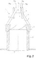
- FIGS Figures 2 and 3 A schematic construction of such a premix burner arrangement is shown in FIGS Figures 2 and 3 shown.
- FIG. 2 shows a longitudinal section
- FIG. 3 a cross section through the premix burner assembly, which provides a conically expanding swirler 1, which is bounded by swirl shells 2.
- liquid fuel B L passes through an injection nozzle 3 positioned along the burner axis A at the location of the smallest inner diameter of the swirl generator 1 into the swirl chamber.
- Longitudinal tangential air inlet slots 4 enters via the combustion air L with tangential flow direction in the swirl space, gaseous fuel B G , preferably mixed in the form of natural gas combustion air.
- injection devices 5 are provided, which are arranged coaxially around the burner axis A and serve the additional feed of medium calorific fuel B M.
- FIG. 3 shows a cross section through the swirl generator 1 in the region of the swirl shells 2 passing through Eindüsungsvorraumen 5.
- the air inlet slots 4 are better visible, penetrates through the air L into the interior of the swirl generator 1.
- gaseous fuel B G is added via appropriate supply lines at the location of the air inlet slots.
- the object of the present invention is to provide a premix burner, in which the above disadvantages do not occur and in particular when operating with a hydrogen-containing gaseous fuel having a hydrogen content of at least 50 percent, improved mixing with ensures the combustion air and at the same time ensures stable flow conditions.
- the solution according to the method for the combustion of hydrogen-containing or hydrogen-containing gaseous fuel with a burner which provides a swirl generator, in the liquid fuel centrally along a burner axis to form a conically forming liquid fuel column can be fed, which flows from a tangentially flowing into the swirl generator rotating combustion air flow enclosed and mixed, provides an axially and / or coaxially oriented to the burner axis feed of the hydrogen-containing or hydrogen gaseous fuel within the swirl generator to form a fuel flow with a largely spatially limited flow shape and with a flow pulse, which is maintained within the burner and only in the area of the burner outlet bursts into a turbulent flow form and gel in the context of a forming remindströmzone for ignition depends.
- the necessary arrangement and dimensioning of the means for supplying the hydrogen in the swirl generator of the burner are to be selected in a way and to integrate in the burner, so that the optimized for the combustion of liquid fuel and natural gas construction of the burner is not or only slightly affected ,
- the hydrogen feed takes place in such a way that, as soon as possible after the hydrogen has left the supply lines, an efficient mixing of the hydrogen with the combustion air takes place in order to avoid local hydrogen concentrations within the burner, which are the cause of the spontaneous ignition phenomena by way of self-ignition.
- care must be taken to minimize the average hydrogen residence time within the burner. This implies that the axial flow rate of the forming within the burner hydrogen-air mixture is very high.
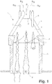
- FIG. 1 illustrated longitudinal section through a premix burner with swirl generator 1, a transition piece 6 and subsequent mixing tube 8, the forming within the burner ideal flow conditions are to be explained under which hydrogen or hydrogen-containing fuel to be fed into the interior of the burner.
- a plurality of supply lines 5 are provided, of which in FIG. 1 only two are shown, which are arranged coaxially about the burner axis A.
- FIG. 2 For the sake of completeness, reference will briefly be made to the other means of fuel injection which, moreover, has already been made with reference to FIG. 2 are described.
- liquid fuel preferably petroleum B L
- fuel lines provided along the air inlet slots 4 allow the introduction of gaseous fuel B G , such as natural gas.
- gaseous fuel B G such as natural gas.
- This flow case is in FIG. 1 shown in case example b.
- the hydrogen flow 9 provides a greater flow impulse, ie if the hydrogen flow is introduced from the supply lines 5 into the burner space with a greater flow velocity, then the flow shape will remain even after leaving the burner, ie within the combustion chamber, as in the case of example a is shown. In this case, combustion occurs by way of diffusion, which leads to increased nitrogen oxide emissions.
- the flow impulse is too low, the hydrogen flow 9 still bursts within the burner, as shown in the case of example c. In this case, preferential ignition occurs within the burner, especially since the residence time of hydrogen within the burner is very high.
- too low a flow pulse leads to a reduced mixing of the hydrogen flow with the combustion air due to only a small lateral flow penetration.
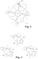
- supply lines 5 are provided for the supply of hydrogen in the swirl chamber of the swirl generator 1 limiting swirl shells 2, according to image representations in the FIGS. 4a to c. Basically, it is important to make the line diameter of the supply lines 5 smaller than in the case of the previously known feed of low or medium calorific fuels.
- FIGS. 4a to c in each case a partial cross-sectional view is represented by a swirl shell 2, in which different arrangements of supply lines 5, through which hydrogen is fed into the swirl space, are provided.
- FIG. 4a to c in each case a partial cross-sectional view is represented by a swirl shell 2, in which different arrangements of supply lines 5, through which hydrogen is fed into the swirl space, are provided.
- FIG. 4a four supply lines 5 are provided, which are positioned differently relative to the burner axis A both in the radial and in the circular arrangement.
- the embodiment according to FIG. 4b provides a plurality of smaller sized in the line cross-section supply lines 5, which are each about the burner axis A largely concentric are arranged.
- the embodiment according to Figure 4c provides for the choice of different sized feed lines 5, wherein the radially outer feed lines 5 have a larger line cross-section than the inner lying. This has the consequence that the hydrogen flow increases with increasing distance to the burner axis A.
- suitable nozzles which, in the simplest case, are designed as simple hole nozzles or in the form of suitable venturi nozzles or similar nozzle arrangements. It is thus possible to influence the flow shape of the hydrogen flow forming in the burner by suitable nozzle selection, for example to form a flow with an elliptical, rectangular or triangular flow cross-section. Depending on the selected flow form, the mixing efficiency of the hydrogen flow with the combustion air surrounding the hydrogen flow can be influenced and improved.
- FIG. 5 which also represents a partial cross-section through a swirl shell 2, in which a supply line 5 is representatively provided for a plurality of further supply lines.
- the feed line 5 has a radial component r c and / or a tangential component t c .
- the feed line 5 is inclined towards the burner axis A, so that the fuel jet emerging from the feed line 5 is inclined at a predeterminable radial angle relative to the burner axis A.
- the orientation of the tangential inclination is preferably to be carried out in such a way that the hydrogen flow emerging from the supply line 5 flows out in the same swirl direction about the burner axis A, with which the combustion air also flows through the air inlet slots 4 into the swirl generator 1.
- the setting of the tangential component t c or of the tangential angle are also to be selected such that the hydrogen flows emerging from the supply lines do not impinge directly on adjacent component walls.
- the average residence time of the hydrogen flow discharged into the burner should not be extended excessively.
- FIG. 6 is representative of other supply lines a supply line 5 is shown, from which a hydrogen flow emerges, which provides a clockwise oriented e-spin E (see arrow).
- e-spin E see arrow
- corresponding flow baffles impressing the self-spin into the flow can be provided.
- the internal swirl is to be set with a swirl number ⁇ of much smaller than 1, preferably smaller than 0.5, where ⁇ is the ratio of the axial flow of the tangential flow torque and the axial flow of the axial flow torque , In this case, vertebral collapses are largely avoided.
- FIG. 7a, b A further alternative measure for improving the mixing properties of a hydrogen flow with the surrounding combustion air is shown.
- the feed line 5 is designed as a ring line 11, or has at the line outlet an annular exit geometry, through which the hydrogen flow enters the swirl generator.
- the ring-shaped hydrogen flow increases its surface area compared to a standard flow such as that which can be generated from a simple single-hole opening and, as a result, is able to mix more efficiently with the surrounding combustion air.
- annular hydrogen flow can be combined as desired to further improve the mixing ratios with the measures already described above for improving the mixing between hydrogen flow and combustion air.
- FIG. 7b is a longitudinal section through the outlet region of a supply line 5 shown, in which a wedge-shaped displacement body 10 is introduced, through which exits the supply line 5 hydrogen flow exits with a predetermined divergence.
- the annular dark hatched region 11 of the supply line 5 is the region from which hydrogen exits.
- the bright, central circular area corresponds to an air supply line, is discharged from the air, which is surrounded by the annular hydrogen flow.
- FIG. 8b the opposite case is shown.
- hydrogen emerges from the inner bright flow region in the form of a hydrogen flow, which is surrounded by a circular, annular air flow 11.
- the flow rate at which each of the air flow exiting from the respective flow regions of the supply line 5 is greater than that speed at which the combustion air flows through the burner axially.
- a measure which further improves the degree of mixing provides, instead of a uniform annular flow, the arrangement of a multiplicity of small flow channels arranged along a ring shape, through which air flows out and forms a ring flow, which circularly surrounds a hydrogen flow forming centrally in the form of a ring.
- a preferred application of the measures described above for supplying a premix burner with hydrogen as fuel provides for the firing of combustion chambers for driving gas turbine plants.
- a quite common combination of gas turbine plants with a so-called integrated gas synthesis (IGCC, Integrated Gasification Combined Cycle) has conventional fuel decarbonizing units through which hydrogen-enriched fuels can be recovered which can be fed to the premix burner according to the invention.
- IGCC integrated gas synthesis
- As part of the decarbonization equally large quantities of nitrogen fall under high process pressures, typically by 30 bar, which also has temperatures of about 150 ° C and below.
- the recovered nitrogen can be mixed with the hydrogen fuel to thereby mitigate the hazards associated with the high reactivity of the hydrogen.
- the reactivity of the hydrogen is significantly reduced by the N 2 -Beiimischung.
- N 2 supply instead of the air supply in the in the FIGS. 8 a and b described embodiments N 2 supply.
- a further, alternative measure to reduce the high reactivity and flame velocity of hydrogen provides for the use of catalytic reactors, as described in detail in the embodiment in FIG. 10 evident.
- a catalytic reactor 13 as shown in FIG. 10b integrated.
- Hydrogen H 2 is fed together with air L along the feed line 5 to a mixer unit 14, which mixes the incoming air L with the hydrogen H 2 before the mixture flows into the catalytic reactor 13.
- water H 2 O is formed which, together with the nitrogen-containing nitrogen N 2 and the unoxidized hydrogen H 2, exits the catalytic reactor 13 and via a vortex generator 15 into the interior of the swirl generator 1 arrives.
- the above burner concept enables the combustion of hydrogen and can be readily adapted to existing premix burner systems without changing the burner design adapted to burner operation with conventional liquid and / or gaseous fuels.
- the choice of the length of the mixing section is an essential design parameter.
- mixing tubes have a length that is between one and two times the maximum burner diameter. Depending on the mode of operation of the premix burner, it is possible to select a length of the mixing tube which is optimized in accordance with the fuel type.
Landscapes
- Engineering & Computer Science (AREA)
- Chemical & Material Sciences (AREA)
- Combustion & Propulsion (AREA)
- Mechanical Engineering (AREA)
- General Engineering & Computer Science (AREA)
- Chemical Kinetics & Catalysis (AREA)
- Pre-Mixing And Non-Premixing Gas Burner (AREA)
Applications Claiming Priority (2)
| Application Number | Priority Date | Filing Date | Title |
|---|---|---|---|
| CH19712004 | 2004-11-30 | ||
| PCT/EP2005/055985 WO2006058843A1 (de) | 2004-11-30 | 2005-11-15 | Verfahren und vorrichtung zur verbrennung von wasserstoff in einem vormischbrenner |
Publications (2)
| Publication Number | Publication Date |
|---|---|
| EP1817526A1 EP1817526A1 (de) | 2007-08-15 |
| EP1817526B1 true EP1817526B1 (de) | 2019-03-20 |
Family
ID=34974223
Family Applications (1)
| Application Number | Title | Priority Date | Filing Date |
|---|---|---|---|
| EP05821548.4A Expired - Lifetime EP1817526B1 (de) | 2004-11-30 | 2005-11-15 | Verfahren und vorrichtung zur verbrennung von wasserstoff in einem vormischbrenner |
Country Status (5)
| Country | Link |
|---|---|
| US (1) | US7871262B2 (enExample) |
| EP (1) | EP1817526B1 (enExample) |
| JP (1) | JP4913746B2 (enExample) |
| CN (1) | CN101069039B (enExample) |
| WO (1) | WO2006058843A1 (enExample) |
Cited By (1)
| Publication number | Priority date | Publication date | Assignee | Title |
|---|---|---|---|---|
| DE102021103247A1 (de) | 2021-02-11 | 2022-08-11 | Vaillant Gmbh | Verfahren und Anordnung zur Reduzierung einer Verbrennungstemperatur bei der Verbrennung von Wasserstoff und Luft in einem Heizgerät |
Families Citing this family (34)
| Publication number | Priority date | Publication date | Assignee | Title |
|---|---|---|---|---|
| CN101069039B (zh) | 2004-11-30 | 2011-10-19 | 阿尔斯托姆科技有限公司 | 用于在预混合燃烧器中燃烧氢气的方法和设备 |
| EP2058590B1 (de) | 2007-11-09 | 2016-03-23 | Alstom Technology Ltd | Verfahren zum Betrieb eines Brenners |
| EP2225488B1 (de) | 2007-11-27 | 2013-07-17 | Alstom Technology Ltd | Vormischbrenner für eine gasturbine |
| CN101910723B (zh) | 2007-11-27 | 2013-07-24 | 阿尔斯通技术有限公司 | 用于在预混燃烧器中燃烧氢气的设备 |
| JP5473934B2 (ja) * | 2007-11-27 | 2014-04-16 | アルストム テクノロジー リミテッド | 水素を多く含む第二の燃料を用いてガスタービン設備を動作させる装置及び方法 |
| EP2072899B1 (en) * | 2007-12-19 | 2016-03-30 | Alstom Technology Ltd | Fuel injection method |
| WO2009109454A1 (de) * | 2008-03-07 | 2009-09-11 | Alstom Technology Ltd | Verfahren und brenneranordnung zum erzeugen von heissgas sowie anwendung des verfahrens |
| EP2252831B1 (de) | 2008-03-07 | 2013-05-08 | Alstom Technology Ltd | Brenneranordnung sowie anwendung einer solchen brenner-anordnung |
| JP5449205B2 (ja) * | 2008-03-07 | 2014-03-19 | アルストム テクノロジー リミテッド | バーナ装置およびこのようなバーナ装置の使用方法 |
| US8650881B2 (en) | 2009-06-30 | 2014-02-18 | General Electric Company | Methods and apparatus for combustor fuel circuit for ultra low calorific fuels |
| CH701905A1 (de) * | 2009-09-17 | 2011-03-31 | Alstom Technology Ltd | Verfahren zum Verbrennen wasserstoffreicher, gasförmiger Brennstoffe in einem Brenner sowie Brenner zur Durchführung des Verfahrens. |
| US20120129111A1 (en) * | 2010-05-21 | 2012-05-24 | Fives North America Combustion, Inc. | Premix for non-gaseous fuel delivery |
| WO2012056750A1 (ja) * | 2010-10-29 | 2012-05-03 | 有限会社T&K | 燃焼方法と燃焼装置 |
| US9134023B2 (en) * | 2012-01-06 | 2015-09-15 | General Electric Company | Combustor and method for distributing fuel in the combustor |
| JP5584260B2 (ja) * | 2012-08-08 | 2014-09-03 | 日野自動車株式会社 | 排気浄化装置用バーナー |
| CN107110506B (zh) | 2014-12-25 | 2019-09-06 | 川崎重工业株式会社 | 烧嘴、燃烧器以及燃气轮机 |
| US10890329B2 (en) | 2018-03-01 | 2021-01-12 | General Electric Company | Fuel injector assembly for gas turbine engine |
| CN108413444B (zh) * | 2018-03-29 | 2023-11-21 | 中国科学院工程热物理研究所 | 预混燃烧器 |
| CN109301291B (zh) * | 2018-08-28 | 2021-05-11 | 中国北方发动机研究所(天津) | 燃料电池用废氢排放结构、排放系统及排放控制方法 |
| US10935245B2 (en) | 2018-11-20 | 2021-03-02 | General Electric Company | Annular concentric fuel nozzle assembly with annular depression and radial inlet ports |
| US11286884B2 (en) | 2018-12-12 | 2022-03-29 | General Electric Company | Combustion section and fuel injector assembly for a heat engine |
| US11073114B2 (en) | 2018-12-12 | 2021-07-27 | General Electric Company | Fuel injector assembly for a heat engine |
| US11156360B2 (en) | 2019-02-18 | 2021-10-26 | General Electric Company | Fuel nozzle assembly |
| CN109973993B (zh) * | 2019-03-04 | 2024-11-22 | 深圳粤通新能源环保技术有限公司 | 一种氢气、天然气混合低碳燃烧机 |
| EP4226084A4 (en) * | 2020-10-06 | 2024-11-27 | Bloom Engineering Company, Inc. | BURNER AND METHOD FOR COMBUSTING HYDROGEN WITH ENHANCED BRIGHTNESS |
| US20220290862A1 (en) * | 2021-03-11 | 2022-09-15 | General Electric Company | Fuel mixer |
| CN113337321A (zh) * | 2021-05-17 | 2021-09-03 | 西安交通大学 | 天然气作为氢气阻燃剂的用途及适用于氢氧燃烧器的燃料 |
| CN113847597B (zh) * | 2021-09-14 | 2023-10-10 | 中国空气动力研究与发展中心空天技术研究所 | 一种气体燃料预混旋流粒子发生装置 |
| DE102021210662B4 (de) * | 2021-09-24 | 2025-07-10 | Benninghoven Zweigniederlassung Der Wirtgen Mineral Technologies Gmbh | Vorrichtung und Verfahren zum Trocknen von Material sowie Asphaltmischanlage mit einer derartigen Vorrichtung |
| CN114183772A (zh) * | 2021-11-30 | 2022-03-15 | 哈尔滨工程大学 | 一种氢气预混的高效低排放燃烧室头部 |
| US12454909B2 (en) | 2021-12-03 | 2025-10-28 | General Electric Company | Combustor size rating for a gas turbine engine using hydrogen fuel |
| US12331932B2 (en) | 2022-01-31 | 2025-06-17 | General Electric Company | Turbine engine fuel mixer |
| US12215866B2 (en) | 2022-02-18 | 2025-02-04 | General Electric Company | Combustor for a turbine engine having a fuel-air mixer including a set of mixing passages |
| CN115479272B (zh) * | 2022-08-16 | 2025-03-14 | 广东中鹏热能科技股份有限公司 | 一种氢气天然气混烧燃烧器 |
Family Cites Families (65)
| Publication number | Priority date | Publication date | Assignee | Title |
|---|---|---|---|---|
| JPS537843A (en) * | 1976-07-10 | 1978-01-24 | Kawasaki Steel Corp | Combustion method of gas fuel in industrial furnace and combustion burner |
| JPS5535885A (en) * | 1978-09-06 | 1980-03-13 | Kobe Steel Ltd | Combustion method capable of minimizing production of nitrogen oxide and smoke |
| JPS6044088B2 (ja) * | 1979-09-29 | 1985-10-01 | ブラザー工業株式会社 | 異常検出装置を備えたタツプ盤 |
| CH674561A5 (enExample) | 1987-12-21 | 1990-06-15 | Bbc Brown Boveri & Cie | |
| US6155212A (en) * | 1989-06-12 | 2000-12-05 | Mcalister; Roy E. | Method and apparatus for operation of combustion engines |
| US5044931A (en) * | 1990-10-04 | 1991-09-03 | Selas Corporation Of America | Low NOx burner |
| US5307634A (en) | 1992-02-26 | 1994-05-03 | United Technologies Corporation | Premix gas nozzle |
| DE4304213A1 (de) * | 1993-02-12 | 1994-08-18 | Abb Research Ltd | Brenner zum Betrieb einer Brennkraftmaschine, einer Brennkammer einer Gasturbogruppe oder Feuerungsanlage |
| CH687831A5 (de) * | 1993-04-08 | 1997-02-28 | Asea Brown Boveri | Vormischbrenner. |
| DE4330083A1 (de) * | 1993-09-06 | 1995-03-09 | Abb Research Ltd | Verfahren zum Betrieb eines Vormischbrenners |
| US5415114A (en) * | 1993-10-27 | 1995-05-16 | Rjc Corporation | Internal air and/or fuel staged controller |
| US5500030A (en) * | 1994-03-03 | 1996-03-19 | Combustion Tec, Inc. | Oxy-gas fired forehearth burner system |
| DE4409918A1 (de) * | 1994-03-23 | 1995-09-28 | Abb Management Ag | Brenner zum Betrieb einer Brennkammer |
| DE4417769A1 (de) * | 1994-05-20 | 1995-11-23 | Abb Research Ltd | Verfahren zum Betrieb eines Vormischbrenners |
| DE4426353A1 (de) * | 1994-07-25 | 1996-02-01 | Abb Research Ltd | Brenner |
| DE4435266A1 (de) * | 1994-10-01 | 1996-04-04 | Abb Management Ag | Brenner |
| DE4435473A1 (de) * | 1994-10-04 | 1996-04-11 | Abb Management Ag | Vormischbrenner für flüssigen Brennstoff |
| US5516281A (en) * | 1995-02-06 | 1996-05-14 | Molodow; Marvin A. | Multiple jet burner |
| DE19527453B4 (de) * | 1995-07-27 | 2009-05-07 | Alstom | Vormischbrenner |
| DE19547913A1 (de) | 1995-12-21 | 1997-06-26 | Abb Research Ltd | Brenner für einen Wärmeerzeuger |
| DE19547912A1 (de) * | 1995-12-21 | 1997-06-26 | Abb Research Ltd | Brenner für einen Wärmeerzeuger |
| DE19547914A1 (de) * | 1995-12-21 | 1997-06-26 | Abb Research Ltd | Vormischbrenner für einen Wärmeerzeuger |
| CN1162089A (zh) * | 1995-12-21 | 1997-10-15 | Abb研究有限公司 | 热发生器的燃烧器 |
| DE19548853A1 (de) * | 1995-12-27 | 1997-07-03 | Abb Research Ltd | Kegelbrenner |
| DE19610930A1 (de) * | 1996-03-20 | 1997-09-25 | Abb Research Ltd | Brenner für einen Wärmeerzeuger |
| DE19626240A1 (de) * | 1996-06-29 | 1998-01-02 | Abb Research Ltd | Vormischbrenner und Verfahren zum Betrieb des Brenners |
| US5954496A (en) * | 1996-09-25 | 1999-09-21 | Abb Research Ltd. | Burner for operating a combustion chamber |
| DE19639301A1 (de) * | 1996-09-25 | 1998-03-26 | Abb Research Ltd | Brenner zum Betrieb einer Brennkammer |
| DE19640198A1 (de) * | 1996-09-30 | 1998-04-02 | Abb Research Ltd | Vormischbrenner |
| DE19654116A1 (de) * | 1996-12-23 | 1998-06-25 | Abb Research Ltd | Brenner zum Betrieb einer Brennkammer mit einem flüssigen und/oder gasförmigen Brennstoff |
| ES2155663T3 (es) * | 1997-03-18 | 2001-05-16 | Alstom Power Schweiz Ag | Procedimiento para el funcionamiento de un quemador estabilizado por torbellinos, asi como quemador para la realizacion del procedimiento. |
| DE19721937B4 (de) * | 1997-05-26 | 2008-12-11 | Alstom | Vormischbrenner zum Betrieb eines Aggregates zur Erzeugung eines Heissgases |
| DE19736902A1 (de) * | 1997-08-25 | 1999-03-04 | Abb Research Ltd | Brenner für einen Wärmeerzeuger |
| EP0908671B1 (de) * | 1997-10-08 | 2003-05-14 | ALSTOM (Switzerland) Ltd | Verfahren zur Verbrennung von gasförmigen, flüssigen sowie mittel-oder niederkalorischen Brennstoffen in einem Brenner |
| ATE234444T1 (de) * | 1997-10-27 | 2003-03-15 | Alstom Switzerland Ltd | Verfahren zum betrieb eines vormischbrenners |
| EP0913630B1 (de) * | 1997-10-31 | 2003-03-05 | ALSTOM (Switzerland) Ltd | Brenner für den Betrieb eines Wärmeerzeugers |
| DE59710788D1 (de) * | 1997-11-13 | 2003-10-30 | Alstom Switzerland Ltd | Brenner für den Betrieb eines Wärmeerzeugers |
| EP0918190A1 (de) * | 1997-11-21 | 1999-05-26 | Abb Research Ltd. | Brenner für den Betrieb eines Wärmeerzeugers |
| EP0919768B1 (de) * | 1997-11-25 | 2003-02-05 | Alstom | Brenner zum Betrieb eines Wärmeerzeugers |
| DE19757189B4 (de) * | 1997-12-22 | 2008-05-08 | Alstom | Verfahren zum Betrieb eines Brenners eines Wärmeerzeugers |
| DE59807856D1 (de) * | 1998-01-23 | 2003-05-15 | Alstom Switzerland Ltd | Brenner für den Betrieb eines Wärmeerzeugers |
| EP0994300B1 (de) * | 1998-10-14 | 2003-11-26 | ALSTOM (Switzerland) Ltd | Brenner für den Betrieb eines Wärmeerzeugers |
| JP2000130757A (ja) * | 1998-10-23 | 2000-05-12 | Hitachi Ltd | ガス化発電プラントのガスタービン燃焼器 |
| EP1002992B1 (de) * | 1998-11-18 | 2004-09-29 | ALSTOM Technology Ltd | Brenner |
| DE19859829A1 (de) * | 1998-12-23 | 2000-06-29 | Abb Alstom Power Ch Ag | Brenner zum Betrieb eines Wärmeerzeugers |
| DE19914666B4 (de) * | 1999-03-31 | 2009-08-20 | Alstom | Brenner für einen Wärmeerzeuger |
| DE19917662C2 (de) * | 1999-04-19 | 2001-10-31 | Elco Kloeckner Heiztech Gmbh | Brenner für flüssigen und/oder gasförmigen Brennstoff |
| DE59907942D1 (de) * | 1999-07-22 | 2004-01-15 | Alstom Switzerland Ltd | Vormischbrenner |
| EP1070915B1 (de) | 1999-07-22 | 2004-05-19 | ALSTOM Technology Ltd | Vormischbrenner |
| AU2001272682A1 (en) * | 2000-06-15 | 2001-12-24 | Alstom Power N.V. | Method for operating a burner and burner with stepped premix gas injection |
| AU2002218784A1 (en) * | 2000-07-11 | 2002-01-21 | L'air Liquide, Societe Anonyme A Directoire Et Conseil De Surveillance Pour L'etude Et L'exploitation Des Procedes Georges Claude | Method and apparatus for furnace air supply enrichment |
| US6729874B2 (en) * | 2000-07-27 | 2004-05-04 | John Zink Company, Llc | Venturi cluster, and burners and methods employing such cluster |
| DE10042315A1 (de) * | 2000-08-29 | 2002-03-14 | Alstom Power Nv | Brenner für einen Wärmeerzeuger |
| DE10050248A1 (de) * | 2000-10-11 | 2002-04-18 | Alstom Switzerland Ltd | Brenner |
| DE10055408A1 (de) * | 2000-11-09 | 2002-05-23 | Alstom Switzerland Ltd | Verfahren zur Brenstoffeinspritzung in einen Brenner |
| DE10061526A1 (de) * | 2000-12-11 | 2002-06-20 | Alstom Switzerland Ltd | Vormischbrenneranordnung zum Betrieb einer Brennkammer |
| DE10061527A1 (de) * | 2000-12-11 | 2002-06-13 | Alstom Switzerland Ltd | Vormischbrenneranordnung mit katalytischer Verbrennung sowie Verfahren zum Betrieb hierzu |
| DE10064259B4 (de) * | 2000-12-22 | 2012-02-02 | Alstom Technology Ltd. | Brenner mit hoher Flammenstabilität |
| DE50212720D1 (de) * | 2001-04-30 | 2008-10-16 | Alstom Technology Ltd | Katalytischer Brenner |
| DE50212753D1 (de) * | 2001-07-26 | 2008-10-23 | Alstom Technology Ltd | Vormischbrenner mit hoher Flammenstabilität |
| US6790030B2 (en) * | 2001-11-20 | 2004-09-14 | The Regents Of The University Of California | Multi-stage combustion using nitrogen-enriched air |
| DE10164099A1 (de) * | 2001-12-24 | 2003-07-03 | Alstom Switzerland Ltd | Brenner mit gestufter Brennstoffeinspritzung |
| US6773256B2 (en) * | 2002-02-05 | 2004-08-10 | Air Products And Chemicals, Inc. | Ultra low NOx burner for process heating |
| DE10233161B4 (de) * | 2002-07-22 | 2012-01-05 | Alstom Technology Ltd. | Brenner und Pilotbrenner |
| CN101069039B (zh) | 2004-11-30 | 2011-10-19 | 阿尔斯托姆科技有限公司 | 用于在预混合燃烧器中燃烧氢气的方法和设备 |
-
2005
- 2005-11-15 CN CN2005800410039A patent/CN101069039B/zh not_active Expired - Fee Related
- 2005-11-15 EP EP05821548.4A patent/EP1817526B1/de not_active Expired - Lifetime
- 2005-11-15 JP JP2007541942A patent/JP4913746B2/ja not_active Expired - Fee Related
- 2005-11-15 WO PCT/EP2005/055985 patent/WO2006058843A1/de not_active Ceased
-
2007
- 2007-05-23 US US11/752,359 patent/US7871262B2/en not_active Expired - Lifetime
Non-Patent Citations (1)
| Title |
|---|
| None * |
Cited By (1)
| Publication number | Priority date | Publication date | Assignee | Title |
|---|---|---|---|---|
| DE102021103247A1 (de) | 2021-02-11 | 2022-08-11 | Vaillant Gmbh | Verfahren und Anordnung zur Reduzierung einer Verbrennungstemperatur bei der Verbrennung von Wasserstoff und Luft in einem Heizgerät |
Also Published As
| Publication number | Publication date |
|---|---|
| JP4913746B2 (ja) | 2012-04-11 |
| CN101069039B (zh) | 2011-10-19 |
| US20080280239A1 (en) | 2008-11-13 |
| CN101069039A (zh) | 2007-11-07 |
| US7871262B2 (en) | 2011-01-18 |
| JP2008522123A (ja) | 2008-06-26 |
| WO2006058843A1 (de) | 2006-06-08 |
| EP1817526A1 (de) | 2007-08-15 |
Similar Documents
| Publication | Publication Date | Title |
|---|---|---|
| EP1817526B1 (de) | Verfahren und vorrichtung zur verbrennung von wasserstoff in einem vormischbrenner | |
| EP2058590B1 (de) | Verfahren zum Betrieb eines Brenners | |
| EP0710797B1 (de) | Verfahren und Vorrichtung zum Betrieb eines Vormischbrenners | |
| EP0675322B1 (de) | Vormischbrenner | |
| DE19533055B4 (de) | Doppelbrennstoffmischer für eine Gasturbinenbrennkammer | |
| EP1504222B1 (de) | Vormischbrenner | |
| EP2116766B1 (de) | Brenner mit Brennstofflanze | |
| EP2220433B1 (de) | Verfahren und vorrichtung zur verbrennung von wasserstoff in einem vormischbrenner | |
| EP0687860B1 (de) | Brennkammer mit Selbstzündung | |
| DE4446945B4 (de) | Gasbetriebener Vormischbrenner | |
| WO2006069861A1 (de) | Vormischbrenner mit mischstrecke | |
| DE4411623A1 (de) | Vormischbrenner | |
| DE4304213A1 (de) | Brenner zum Betrieb einer Brennkraftmaschine, einer Brennkammer einer Gasturbogruppe oder Feuerungsanlage | |
| EP2257736B1 (de) | Verfahren zum erzeugen von heissgas | |
| DE4416650A1 (de) | Verbrennungsverfahren für atmosphärische Feuerungsanlagen | |
| EP1861657A1 (de) | Verfahren und vorrichtung zur verbrennung von wasserstoff in einem vormischbrenner | |
| EP2513562A1 (de) | Brenner für eine turbine | |
| EP0908671B1 (de) | Verfahren zur Verbrennung von gasförmigen, flüssigen sowie mittel-oder niederkalorischen Brennstoffen in einem Brenner | |
| EP0276397A1 (de) | Brennkammer für Gasturbine | |
| EP2410276B2 (de) | Verfahren zur chemischen umsetzung eines brennstoffs mit sauerstoffhaltigem gas mittels eines aussenmischenden brenners | |
| DE102005038662B4 (de) | Brennkopf und Verfahren zur Verbrennung von Brennstoff | |
| DE4330160A1 (de) | Verfahren zum Betreiben eines Brenners mit gasförmigen oder flüssigen Brennstoffen sowie Brenner zur Durchführung des Verfahrens | |
| DE19542644A1 (de) | Vormischverbrennung | |
| DE112010003677B4 (de) | Verfahren zum verbrennen wasserstoffreicher, gasförmiger brennstoffe in einem brenner sowie brenner zur durchführung des verfahrens | |
| DE2459001C3 (de) | Brennkammer, insbesondere für Staustrahltriebwerke |
Legal Events
| Date | Code | Title | Description |
|---|---|---|---|
| PUAI | Public reference made under article 153(3) epc to a published international application that has entered the european phase |
Free format text: ORIGINAL CODE: 0009012 |
|
| 17P | Request for examination filed |
Effective date: 20070514 |
|
| AK | Designated contracting states |
Kind code of ref document: A1 Designated state(s): AT BE BG CH CY CZ DE DK EE ES FI FR GB GR HU IE IS IT LI LT LU LV MC NL PL PT RO SE SI SK TR |
|
| DAX | Request for extension of the european patent (deleted) | ||
| 17Q | First examination report despatched |
Effective date: 20160523 |
|
| RAP1 | Party data changed (applicant data changed or rights of an application transferred) |
Owner name: GENERAL ELECTRIC TECHNOLOGY GMBH |
|
| STAA | Information on the status of an ep patent application or granted ep patent |
Free format text: STATUS: EXAMINATION IS IN PROGRESS |
|
| RAP1 | Party data changed (applicant data changed or rights of an application transferred) |
Owner name: ANSALDO ENERGIA SWITZERLAND AG |
|
| GRAP | Despatch of communication of intention to grant a patent |
Free format text: ORIGINAL CODE: EPIDOSNIGR1 |
|
| STAA | Information on the status of an ep patent application or granted ep patent |
Free format text: STATUS: GRANT OF PATENT IS INTENDED |
|
| RIC1 | Information provided on ipc code assigned before grant |
Ipc: F23C 13/00 20060101ALI20180912BHEP Ipc: F23R 3/28 20060101ALI20180912BHEP Ipc: F23C 99/00 20060101AFI20180912BHEP Ipc: F23D 17/00 20060101ALI20180912BHEP |
|
| INTG | Intention to grant announced |
Effective date: 20181009 |
|
| GRAJ | Information related to disapproval of communication of intention to grant by the applicant or resumption of examination proceedings by the epo deleted |
Free format text: ORIGINAL CODE: EPIDOSDIGR1 |
|
| GRAL | Information related to payment of fee for publishing/printing deleted |
Free format text: ORIGINAL CODE: EPIDOSDIGR3 |
|
| GRAS | Grant fee paid |
Free format text: ORIGINAL CODE: EPIDOSNIGR3 |
|
| STAA | Information on the status of an ep patent application or granted ep patent |
Free format text: STATUS: EXAMINATION IS IN PROGRESS |
|
| GRAR | Information related to intention to grant a patent recorded |
Free format text: ORIGINAL CODE: EPIDOSNIGR71 |
|
| STAA | Information on the status of an ep patent application or granted ep patent |
Free format text: STATUS: GRANT OF PATENT IS INTENDED |
|
| GRAA | (expected) grant |
Free format text: ORIGINAL CODE: 0009210 |
|
| STAA | Information on the status of an ep patent application or granted ep patent |
Free format text: STATUS: THE PATENT HAS BEEN GRANTED |
|
| AK | Designated contracting states |
Kind code of ref document: B1 Designated state(s): AT BE BG CH CY CZ DE DK EE ES FI FR GB GR HU IE IS IT LI LT LU LV MC NL PL PT RO SE SI SK TR |
|
| INTG | Intention to grant announced |
Effective date: 20190212 |
|
| REG | Reference to a national code |
Ref country code: GB Ref legal event code: FG4D Free format text: NOT ENGLISH |
|
| REG | Reference to a national code |
Ref country code: CH Ref legal event code: EP |
|
| REG | Reference to a national code |
Ref country code: DE Ref legal event code: R096 Ref document number: 502005016009 Country of ref document: DE |
|
| REG | Reference to a national code |
Ref country code: AT Ref legal event code: REF Ref document number: 1110927 Country of ref document: AT Kind code of ref document: T Effective date: 20190415 |
|
| REG | Reference to a national code |
Ref country code: IE Ref legal event code: FG4D Free format text: LANGUAGE OF EP DOCUMENT: GERMAN |
|
| REG | Reference to a national code |
Ref country code: NL Ref legal event code: MP Effective date: 20190320 |
|
| PG25 | Lapsed in a contracting state [announced via postgrant information from national office to epo] |
Ref country code: SE Free format text: LAPSE BECAUSE OF FAILURE TO SUBMIT A TRANSLATION OF THE DESCRIPTION OR TO PAY THE FEE WITHIN THE PRESCRIBED TIME-LIMIT Effective date: 20190320 Ref country code: FI Free format text: LAPSE BECAUSE OF FAILURE TO SUBMIT A TRANSLATION OF THE DESCRIPTION OR TO PAY THE FEE WITHIN THE PRESCRIBED TIME-LIMIT Effective date: 20190320 Ref country code: LT Free format text: LAPSE BECAUSE OF FAILURE TO SUBMIT A TRANSLATION OF THE DESCRIPTION OR TO PAY THE FEE WITHIN THE PRESCRIBED TIME-LIMIT Effective date: 20190320 |
|
| REG | Reference to a national code |
Ref country code: LT Ref legal event code: MG4D |
|
| PG25 | Lapsed in a contracting state [announced via postgrant information from national office to epo] |
Ref country code: BG Free format text: LAPSE BECAUSE OF FAILURE TO SUBMIT A TRANSLATION OF THE DESCRIPTION OR TO PAY THE FEE WITHIN THE PRESCRIBED TIME-LIMIT Effective date: 20190620 Ref country code: GR Free format text: LAPSE BECAUSE OF FAILURE TO SUBMIT A TRANSLATION OF THE DESCRIPTION OR TO PAY THE FEE WITHIN THE PRESCRIBED TIME-LIMIT Effective date: 20190621 Ref country code: NL Free format text: LAPSE BECAUSE OF FAILURE TO SUBMIT A TRANSLATION OF THE DESCRIPTION OR TO PAY THE FEE WITHIN THE PRESCRIBED TIME-LIMIT Effective date: 20190320 Ref country code: LV Free format text: LAPSE BECAUSE OF FAILURE TO SUBMIT A TRANSLATION OF THE DESCRIPTION OR TO PAY THE FEE WITHIN THE PRESCRIBED TIME-LIMIT Effective date: 20190320 |
|
| PG25 | Lapsed in a contracting state [announced via postgrant information from national office to epo] |
Ref country code: IT Free format text: LAPSE BECAUSE OF FAILURE TO SUBMIT A TRANSLATION OF THE DESCRIPTION OR TO PAY THE FEE WITHIN THE PRESCRIBED TIME-LIMIT Effective date: 20190320 Ref country code: ES Free format text: LAPSE BECAUSE OF FAILURE TO SUBMIT A TRANSLATION OF THE DESCRIPTION OR TO PAY THE FEE WITHIN THE PRESCRIBED TIME-LIMIT Effective date: 20190320 Ref country code: RO Free format text: LAPSE BECAUSE OF FAILURE TO SUBMIT A TRANSLATION OF THE DESCRIPTION OR TO PAY THE FEE WITHIN THE PRESCRIBED TIME-LIMIT Effective date: 20190320 Ref country code: CZ Free format text: LAPSE BECAUSE OF FAILURE TO SUBMIT A TRANSLATION OF THE DESCRIPTION OR TO PAY THE FEE WITHIN THE PRESCRIBED TIME-LIMIT Effective date: 20190320 Ref country code: EE Free format text: LAPSE BECAUSE OF FAILURE TO SUBMIT A TRANSLATION OF THE DESCRIPTION OR TO PAY THE FEE WITHIN THE PRESCRIBED TIME-LIMIT Effective date: 20190320 Ref country code: SK Free format text: LAPSE BECAUSE OF FAILURE TO SUBMIT A TRANSLATION OF THE DESCRIPTION OR TO PAY THE FEE WITHIN THE PRESCRIBED TIME-LIMIT Effective date: 20190320 Ref country code: PT Free format text: LAPSE BECAUSE OF FAILURE TO SUBMIT A TRANSLATION OF THE DESCRIPTION OR TO PAY THE FEE WITHIN THE PRESCRIBED TIME-LIMIT Effective date: 20190720 |
|
| PG25 | Lapsed in a contracting state [announced via postgrant information from national office to epo] |
Ref country code: PL Free format text: LAPSE BECAUSE OF FAILURE TO SUBMIT A TRANSLATION OF THE DESCRIPTION OR TO PAY THE FEE WITHIN THE PRESCRIBED TIME-LIMIT Effective date: 20190320 |
|
| PG25 | Lapsed in a contracting state [announced via postgrant information from national office to epo] |
Ref country code: IS Free format text: LAPSE BECAUSE OF FAILURE TO SUBMIT A TRANSLATION OF THE DESCRIPTION OR TO PAY THE FEE WITHIN THE PRESCRIBED TIME-LIMIT Effective date: 20190720 |
|
| REG | Reference to a national code |
Ref country code: DE Ref legal event code: R097 Ref document number: 502005016009 Country of ref document: DE |
|
| PLBE | No opposition filed within time limit |
Free format text: ORIGINAL CODE: 0009261 |
|
| STAA | Information on the status of an ep patent application or granted ep patent |
Free format text: STATUS: NO OPPOSITION FILED WITHIN TIME LIMIT |
|
| PG25 | Lapsed in a contracting state [announced via postgrant information from national office to epo] |
Ref country code: DK Free format text: LAPSE BECAUSE OF FAILURE TO SUBMIT A TRANSLATION OF THE DESCRIPTION OR TO PAY THE FEE WITHIN THE PRESCRIBED TIME-LIMIT Effective date: 20190320 |
|
| 26N | No opposition filed |
Effective date: 20200102 |
|
| PG25 | Lapsed in a contracting state [announced via postgrant information from national office to epo] |
Ref country code: SI Free format text: LAPSE BECAUSE OF FAILURE TO SUBMIT A TRANSLATION OF THE DESCRIPTION OR TO PAY THE FEE WITHIN THE PRESCRIBED TIME-LIMIT Effective date: 20190320 |
|
| PG25 | Lapsed in a contracting state [announced via postgrant information from national office to epo] |
Ref country code: TR Free format text: LAPSE BECAUSE OF FAILURE TO SUBMIT A TRANSLATION OF THE DESCRIPTION OR TO PAY THE FEE WITHIN THE PRESCRIBED TIME-LIMIT Effective date: 20190320 |
|
| REG | Reference to a national code |
Ref country code: CH Ref legal event code: PL |
|
| PG25 | Lapsed in a contracting state [announced via postgrant information from national office to epo] |
Ref country code: LI Free format text: LAPSE BECAUSE OF NON-PAYMENT OF DUE FEES Effective date: 20191130 Ref country code: MC Free format text: LAPSE BECAUSE OF FAILURE TO SUBMIT A TRANSLATION OF THE DESCRIPTION OR TO PAY THE FEE WITHIN THE PRESCRIBED TIME-LIMIT Effective date: 20190320 Ref country code: LU Free format text: LAPSE BECAUSE OF NON-PAYMENT OF DUE FEES Effective date: 20191115 Ref country code: CH Free format text: LAPSE BECAUSE OF NON-PAYMENT OF DUE FEES Effective date: 20191130 |
|
| REG | Reference to a national code |
Ref country code: BE Ref legal event code: MM Effective date: 20191130 |
|
| GBPC | Gb: european patent ceased through non-payment of renewal fee |
Effective date: 20191115 |
|
| PG25 | Lapsed in a contracting state [announced via postgrant information from national office to epo] |
Ref country code: IE Free format text: LAPSE BECAUSE OF NON-PAYMENT OF DUE FEES Effective date: 20191115 Ref country code: GB Free format text: LAPSE BECAUSE OF NON-PAYMENT OF DUE FEES Effective date: 20191115 Ref country code: FR Free format text: LAPSE BECAUSE OF NON-PAYMENT OF DUE FEES Effective date: 20191130 |
|
| PG25 | Lapsed in a contracting state [announced via postgrant information from national office to epo] |
Ref country code: BE Free format text: LAPSE BECAUSE OF NON-PAYMENT OF DUE FEES Effective date: 20191130 |
|
| REG | Reference to a national code |
Ref country code: AT Ref legal event code: MM01 Ref document number: 1110927 Country of ref document: AT Kind code of ref document: T Effective date: 20191115 |
|
| PG25 | Lapsed in a contracting state [announced via postgrant information from national office to epo] |
Ref country code: AT Free format text: LAPSE BECAUSE OF NON-PAYMENT OF DUE FEES Effective date: 20191115 |
|
| PG25 | Lapsed in a contracting state [announced via postgrant information from national office to epo] |
Ref country code: CY Free format text: LAPSE BECAUSE OF FAILURE TO SUBMIT A TRANSLATION OF THE DESCRIPTION OR TO PAY THE FEE WITHIN THE PRESCRIBED TIME-LIMIT Effective date: 20190320 |
|
| PG25 | Lapsed in a contracting state [announced via postgrant information from national office to epo] |
Ref country code: HU Free format text: LAPSE BECAUSE OF FAILURE TO SUBMIT A TRANSLATION OF THE DESCRIPTION OR TO PAY THE FEE WITHIN THE PRESCRIBED TIME-LIMIT; INVALID AB INITIO Effective date: 20051115 |
|
| PGFP | Annual fee paid to national office [announced via postgrant information from national office to epo] |
Ref country code: DE Payment date: 20211118 Year of fee payment: 17 |
|
| REG | Reference to a national code |
Ref country code: DE Ref legal event code: R119 Ref document number: 502005016009 Country of ref document: DE |
|
| PG25 | Lapsed in a contracting state [announced via postgrant information from national office to epo] |
Ref country code: DE Free format text: LAPSE BECAUSE OF NON-PAYMENT OF DUE FEES Effective date: 20230601 |