EP1810871A2 - Verrouillage de siège de véhicule - Google Patents
Verrouillage de siège de véhicule Download PDFInfo
- Publication number
- EP1810871A2 EP1810871A2 EP07100922A EP07100922A EP1810871A2 EP 1810871 A2 EP1810871 A2 EP 1810871A2 EP 07100922 A EP07100922 A EP 07100922A EP 07100922 A EP07100922 A EP 07100922A EP 1810871 A2 EP1810871 A2 EP 1810871A2
- Authority
- EP
- European Patent Office
- Prior art keywords
- hook member
- striker
- bell crank
- engagement
- seat back
- Prior art date
- Legal status (The legal status is an assumption and is not a legal conclusion. Google has not performed a legal analysis and makes no representation as to the accuracy of the status listed.)
- Granted
Links
Images


Classifications
-
- B—PERFORMING OPERATIONS; TRANSPORTING
- B60—VEHICLES IN GENERAL
- B60N—SEATS SPECIALLY ADAPTED FOR VEHICLES; VEHICLE PASSENGER ACCOMMODATION NOT OTHERWISE PROVIDED FOR
- B60N2/00—Seats specially adapted for vehicles; Arrangement or mounting of seats in vehicles
- B60N2/02—Seats specially adapted for vehicles; Arrangement or mounting of seats in vehicles the seat or part thereof being movable, e.g. adjustable
- B60N2/04—Seats specially adapted for vehicles; Arrangement or mounting of seats in vehicles the seat or part thereof being movable, e.g. adjustable the whole seat being movable
- B60N2/06—Seats specially adapted for vehicles; Arrangement or mounting of seats in vehicles the seat or part thereof being movable, e.g. adjustable the whole seat being movable slidable
- B60N2/08—Seats specially adapted for vehicles; Arrangement or mounting of seats in vehicles the seat or part thereof being movable, e.g. adjustable the whole seat being movable slidable characterised by the locking device
-
- B—PERFORMING OPERATIONS; TRANSPORTING
- B60—VEHICLES IN GENERAL
- B60N—SEATS SPECIALLY ADAPTED FOR VEHICLES; VEHICLE PASSENGER ACCOMMODATION NOT OTHERWISE PROVIDED FOR
- B60N2/00—Seats specially adapted for vehicles; Arrangement or mounting of seats in vehicles
- B60N2/24—Seats specially adapted for vehicles; Arrangement or mounting of seats in vehicles for particular purposes or particular vehicles
- B60N2/32—Seats specially adapted for vehicles; Arrangement or mounting of seats in vehicles for particular purposes or particular vehicles convertible for other use
- B60N2/36—Seats specially adapted for vehicles; Arrangement or mounting of seats in vehicles for particular purposes or particular vehicles convertible for other use into a loading platform
- B60N2/366—Seats specially adapted for vehicles; Arrangement or mounting of seats in vehicles for particular purposes or particular vehicles convertible for other use into a loading platform characterised by the locking device
-
- B—PERFORMING OPERATIONS; TRANSPORTING
- B60—VEHICLES IN GENERAL
- B60N—SEATS SPECIALLY ADAPTED FOR VEHICLES; VEHICLE PASSENGER ACCOMMODATION NOT OTHERWISE PROVIDED FOR
- B60N2/00—Seats specially adapted for vehicles; Arrangement or mounting of seats in vehicles
- B60N2/02—Seats specially adapted for vehicles; Arrangement or mounting of seats in vehicles the seat or part thereof being movable, e.g. adjustable
- B60N2/22—Seats specially adapted for vehicles; Arrangement or mounting of seats in vehicles the seat or part thereof being movable, e.g. adjustable the back-rest being adjustable
- B60N2/2245—Seats specially adapted for vehicles; Arrangement or mounting of seats in vehicles the seat or part thereof being movable, e.g. adjustable the back-rest being adjustable provided with a lock mechanism on the upper part of the back-rest
Definitions
- the present invention relates to a vehicle seat lock to hold the seat back of a chair in a standing position, the seat back being capable of standing up or falling down.
- JP8-119010A discloses a vehicle seat lock comprising a hook member mounted to the seat back and engagable with striker of a vehicle body, a locking mechanism comprising a latch member engagable with the hook member, an unlocking knob connected to the latch member and a warning indicator. By the unlocking knob, the latch member is disengaged from the hook member to allow the seat back to move from a standing position to a falling position.
- the warning indicator is retracted in the seat back when the hook member engages with the striker, while it projects from the seat back when the hook member disengages from the striker. Thus, a passenger visually confirms engagement of the hook member with the striker by the warning indicator.
- the warning indicator for showing the engagement of the hook member with the striker is separately provided from the unlocking knob thereby increasing the number of parts and making the structure more complicate.
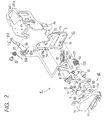
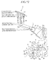
- a rear seat 1 comprises a seat cushion 2 mounted on a body floor, and a seat back 3 which is supported by a hinge shaft (not shown) at the rear end of the seat cushion 2 to enable the seat back 3 to fall down on the seat cushion 2
- a locking assembly 4 is provided below a shoulder part close to a body panel and engages with a metal striker 5 fixed to the body panel to enable the seat back 3 to be held at the first standing position by a solid line and at the second standing position reclined backwards of the first standing position by a dotted line and to enable the seat back 3 to fall down forwards with operation of an operating device 6 in the shoulder part of the seat back 3.
- the striker 5 comprises a base 53 fixed to the body panel facing the side of the seat back 3, and a U-shaped engaging member 54 comprising the first engagement portion 51 and the second engagement portion 52.
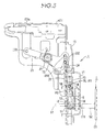
- the locking assembly 4 comprises the first metal base member 7 fixed to a seat frame 31 in Fig. 4 in the seat back 3 with a bolt (not shown), and the second metal base member 11 fixed to the side of the first metal member 7 facing an outside.
- the first and second base members 7,11 have striker-engaging grooves 71,111 in which the first and second engagement portions 51,52 of the striker 5 engage forwards when the seat back 3 stands up.
- a hook member 8 containing metal as matrix to engage with the first or second engagement portions 51,52 of the striker 5 to allow the seat back 3 to be held at the first or second standing position, a synthetic-resin opening lever 9 operated by the operating device 6, and a synthetic-resin sensing member 10 movable depending on engagement of the striker 5 and the hook member 8.
- the mounting bracket 43 may be molded together with the first base member 7.
- the operating device 6 may be mounted to the second base member 11.
- a burring 74 that cylindrically projects rearwards or downwards in Fig. 7, from the first fixing portion 73.
- a female thread is formed to engage with the bolt 18.
- the burring 74 of the first fixing portion 73 engages in the engagement hole 113 of the second fixing portion 112.
- the bolt 18 is screwed in the burring 74.
- the second fixing portion 112 is held between a head 181 of the bolt 18 and the first fixing portion 73.
- the first base member 7 is connected to the second base member 11 after the opening lever 9, the sensing member 10 and the bell crank 23 are mounted to the first base member 7 and after the hook member 8 is mounted to the second base member 11.
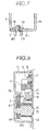
- Fig. 8 is a vertical sectional view taken along the line VIII-VIII in Fig. 6; Fig. 9 is a horizontal sectional view taken along the line IX-IX; Fig. 10 is an enlarged view of the hook member 8; and Figs. 11-15 are views for showing operation.
- the operating device 6, the bell crank 23, the hook member 8, the opening lever 9 and the sensing member 10 are on the same surface.
- the front of the figures is deemed as “rear side”
- the back is deemed as “front side”.
- the opening lever 9 and sensing member 10 the left side of the figures is deemed as “rear side” and the right side is deemed as "front side”.
- the hook member 8 is molded with synthetic resin on the outer circumferential surface of metal.
- a pivot portion 88 is pivotally secured on the first pivot 12 in the striker-engaging groove 111 of the second base member 11 to enable it to move up and down.
- the pivot portion 88 is forced by the first spring 13 to go down.
- the first pivot 12 is positioned on an extension of movement of the striker 5.
- the first spring 13 has one end 131 which engages with the hook member 8 and the other end 132 which engages with a projection 114 of the second base member 11.
- the first pivot 12 has a larger-diameter portion 121 between the first base member 7 and the second base member 11.
- the hook member 8 has the first engagement groove 81 opening downwards and capable of selectively engaging with the first and second engagement portions 51,52; and the second engagement groove 82 capable of engaging with the first engagement portion 51.
- the first arm 84 having an inclined edge 83 is provided in the hook member 8 and the second arm 85 is provided between the first engagement groove 81 and the second engagement groove 82. From the side of the hook member 8, a protrusion 86 projects towards the cabin.
- the hook member 8 When the hook member 8 disengages from the striker 5 or when the seat back 3 folds down, it is held horizontally in a standby position in Figs. 6 and 11.
- the hook member 8 When the first engagement portion 51 or the second engagement portion 52 of the striker 5 engages in the first engagement groove 81, the hook member 8 is held in an engagement position where it slightly rotates upwards from the standby position in Fig. 12 or 15.
- the hook member 8 rotates in an unlocking direction or a clockwise direction in Figs. 6 and 11-15 to shift to the first-step unlocking position in Fig. 13 in which the first engagement portion 51 is releasable from the first engagement groove 81 only rearwards.
- the hook member 8 rotates upwards from the first-step unlocking position and enables it to shift to the second-step unlocking position in Fig. 14 in which the first engagement portion 51 can engage in the second engagement groove 82 from the first engagement groove 81.
- the first engagement portion 51 of the striker 5 engages in the first engagement groove 81 of the hook member 8, and when it is held in the second standing position, the second engagement portion 52 engages in the first engagement groove 81 and the first engagement portion 51 puts in the second engagement groove 82 with play.
- the first and second arms 84,85 project downwards to put on the inner side surface of the second base member 11, and the lower end of the second arm 85 is allowed to contact the lower surface of the second base member 11 when the hook member 8 is in the standby position.
- the first engagement groove 81 is formed like a wedge to reduce a width upwards gradually.
- a width (W1) is set to put the striker 5 between the engagement portions 51 and 52 without loosening.
- the first engagement groove 81 tightly fits in the first engagement portions 51 and 52 thereby preventing the seat back 3 from moving back and forth.
- a receiving edge 8a of the first engagement groove 81 contacts the first and second engagement portions 51,52 of the striker 5 when the seat back 3 is leaned backwards.
- the second arm 85 which comprises the receiving edge 8a and a contact portion 8b continuous with the receiving edge 8a, metal matrix is exposed without synthetic resin molding.
- the front edge of the first arm 84 comprises the inclined edge 83 of the first arm 84 and a coming-out preventing edge 8c which faces the receiving edge 8a of the first engagement groove 81.
- the coming-out-preventing edge 8e contacts the first and second engagement portions 51,52 when the seat back 3 falls down and folds on the seat.
- the front edge is molded with synthetic resin.
- first or second engagement portion 51 or 52 of the striker 5 engages in the first engagement groove 81 of the hook member 8
- metal parts contacts each other. Even though the hook member 8 is molded with synthetic resin, deformation of synthetic resin over the parts does not prevent the hook member 8 from moving out. Thus, the first engagement portion 51 does not engage in the second engagement groove 82 beyond the first engagement groove 81.
- the metal-exposing receiving edge 8a can receive weight of the leaning seat back 3 when a passenger sits down the rear seat 1. Even though the hook member 8 is molded with synthetic resin, neither fast collapse nor deformation of the synthetic resin is prevented thereby assuring stable engagement of the hook member 8 with the striker 5 for a long time.
- the second engagement groove 82 is formed between the second arm 85 and the pivot portion 88 pivotally supported by the first pivot 12.
- a front edge 85a of the second arm 85 comprises an arc of a circle around the first pivot 12 as a center.
- a buffer portion 87 molded with synthetic resin.
- the front edge 85a of the second arm 85 is formed as an arc of a circle around the first pivot 12 as center.
- the buffer portion 87 is positioned out of the movement track L of the first and second engagement portions 51,52 of the striker 5 when the hook member 8 is in an engagement position in Figs. 12 and 15.
- the buffer portion 87 moves into the movement track L when the hook member 8 shifts to the second-step unlocking position in Fig. 14.
- the first engagement portion 51 comes into the second engagement groove 82 of the hook member 8
- the first engagement portion 51 contacts the buffer portion 87 to restrict invasion of the striker 5 and to reduce noise when the striker 5 comes in.
- the hook member 8 rotates from the second-step unlocking position in a direction of engagement or in an anticlockwise direction in Figs.
- the first engagement groove 81 can surely engage with the second engagement portion 52.
- the buffer portion 87 may preferably be molded with the hook member 8 in synthetic resin. Instead, it may be formed separately from the hook member 8.
- An opening lever 9 is pivoted with the second pivot 14 above the striker-engaging groove 71 of the first base member 7, forced in a standby direction or in a clockwise direction in Figs. 6 and 11-15 by the second spring 15 wound on the second pivot 14 and held in the standby position in which a lower acting portion 91 is positioned downwards in Figs. 6, 11, 12 and 15.
- the acting portion 91 is between the hook member 8 and sensing member 10 and allowed to contact a projection 86 of the hook member 8 when the opening lever 9 rotates anticlockwise from the standby position.
- a certain gap is formed not to contact the acting portion 91 with the projection 86 owing to variation of the mounted positions of the hook member 8, striker 5 and other parts.
- the opening lever 9 rotates anticlockwise from the standby position to the first operating position in Fig. 13 to allow the front edge of the acting portion 91 to contact the projection 86 of the hook member 8 to shift the hook member 8 from the engagement position to the first-step unlocking position.
- the opening lever 9 shifts to the second operating position in Fig. 14 in which it rotates further anticlockwise from the first operating position to allow the hook member 8 to shift to the second-step unlocking position.
- the sensing member 10 is pivotally secured on a third pivot 16 above the striker-engaging groove 71 of the first base member 7; forced by a third spring 17 wound around the third pivot 160; and usually held in the standby position in Figs. 6 and 11 in which the upper front portion contacts a stopper 75 of the first base member 7.
- the sensing member 10 has at the lower rear end a contact portion 101 which can go on the first and second engagement portions 51,52 of the striker 5.
- the first engagement portion 51 or second engagement portion 52 of the striker 5 engages in the first engagement groove 81 of the hook member 8 to allow the contact portion 101 to go on the first or second engagement portion 51 or 52 to enable the sensing member 10 to shift to a detecting position to which the standby position rotates upwards in Figs. 12-15.
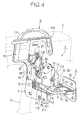
- the operating device 6 As described in Fig. 4, the operating device 6 is exposed from the shoulder of the seat back 3 and comprises a rectangular guide member 20 in a mounting hole 431a of the mounting bracket 43 and an operating knob 21 which is stored to enable it to slide in the guide member 20 up and down.
- the operating knob 21 is connected to a connecting shaft 233 fixed to one end of the bell crank 23 and moved with the bell crank 23 between the first rest position A in which the upper surface is substantially coplanar with the upper surface of the guide member 20 in Figs. 12 and 15 and the second rest position in which the upper surface is retracted in Fig. 11 .
- the upper surface of the operating knob 21 is shifted to the first operating position C in Fig. 13 which is retracted further from the second rest position B and the second operating position D in Fig. 14 which is retracted further from the second operating position C.
- the first or second engagement portion 51 or 52 of the striker 5 engages in the first engagement groove 81 of the hook member and the sensing member 10 is in the detecting position.
- the sensing member 10 is in the standby position and the first and second engagement portions 51,52 disengage from the first engagement groove 81 of the hook member 8.
- the opening lever 9 is moved to the first acting position to allow the hook member 8 to move to the first-step unlocking position.
- the opening lever 9 is moved to the second acting position to allow the hook member 8 to move to the second-step unlocking position.
- an indicator (not shown) comprising a different color from the guide member 20 or letters "UNLOCK".
- the indicator is hindered when the operating knob 21 is in the first rest position A, while it is exposed when the operating knob 21 is out of the first rest position A thereby allowing the passenger to warn that the locking assembly 4 disengages from the striker 5 to improve security.
- the bell crank 23 is pivotally secured on the fourth pivot 22 to the mounting bracket 43 to move up and down, and forced clockwise by a fourth spring 25 wound on the fourth pivot 22 in Figs. 6 and 11-15.
- the bell crank 23 is moved together with the operating knob 21 to the first rest position A1 in Figs. 12 and 15; the second rest position B1 in Fig. 11 to which it rotates anticlockwise from the first rest position AS1; the first operating position C1 in Fig. 13 to which it rotates anticlockwise from the second rest position B1; and the second operating position D1 in Fig. 14 to which it rotates anticlockwise from the first operating position C1.
- the force of the fourth spring 25 acting to the bell crank 23 is set to be smaller than the force of the third spring 17 acting to the sensing member 10.
- the other end of the bell crank 23 has the first elongate opening 231 and second elongate opening 232 extending vertically.
- the upper end 24a of the first connecting rod 24 connected at the lower end to the sensing member 10 engages with play to slide up and down.
- the upper end 26a of the second connecting rod 26 connected at the lower end to the opening lever 9 engages with play to slide up and down.
- the first elongate opening 231 is set to have a length having a play to the upper end 24a of the first connecting rod 24 corresponding to stroke of the bell crank 23 between the first rest position A1 and the second operating position D1 with respect to anticlockwise rotation of the bell crank 23 when the operating knob 21 and bell crank 23 are in the first rest position A, A1.
- motion of the operating knob 21 and bell crank 23 from the first rest position A,A1 to the second operating position D,D1 and vice versa is not transmitted to the sensing member 10.
- the second elongate opening 232 is set to have a length having a play to the upper end 26a of the second connecting rod 26 corresponding to stroke of the bell crank 23 between the first rest position A1 and the second rest position B1 with respect to anticlockwise rotation of the bell crank 23 when the bell crank 23 is in the first rest position A1.
- motion of the operating knob 21 and bell crank 23 from the first rest position A, A1 to the second rest position B,B1 and vice versa is not transmitted to the opening lever 9.
- the operating knob 21 and the bell crank 23 moves from the first rest position A,A1 to the second rest position B,B1 below.
- the sensing member 10 shifts from the detecting position to the standby position, so that the first connecting rod 24 goes down. Following the motion of the sensing member 10, the bell crank 23 shifts by the force of the fourth spring 25 from the second rest position B1 to the first rest position A1.
- the sensing member 10 shifts from the detecting position to the standby position, so that the first connecting rod 25 goes up to allow the upper end 24a to contact the upper edge of the first elongate opening 231 to press up the bell crank 23.
- the bell crank 23 shifts to the second rest position B1 against the force of the fourth spring 25.
- the ends of the pivots 14,16 are previously crimped.
- the opening lever 9 and the sensing member 10 are pivotally connected to the first base member 7 with the pivots 14,16 and the springs 15,17 are connected, so that the first subassembly 41 is formed.
- One end of the first pivot 12 or the end which projects from the second base member 11 is crimped and the hook member 8 is pivotally connected to the second base member 11 with the pivot 12. As shown in Figs. 8 and 9, the hook member 8 is put between the second base member 11 and the larger-diameter portion 121 of the first pivot 12 to enable the hook member 8 to rotate.
- first and second subassemblies 41,42 are formed, a positioning projection 76 of the first base member 7 is engaged in a positioning opening 115 of the second base member 11 and positioned. And the other end of the first pivot 12 is put into an axial hole 72 of the first base member 7 and crimped in Fig. 2.
- first fixing portion 73 is joined to the second fixing portion 112 with a bolt 18 in a direction perpendicular to the pivots 12,14,16.
- the first subassembly 41 and the second subassembly 42 are previously formed, which results in efficient assembling of the locking assembly 4.
- the first base member 7 is connected to the second base member 11 with the bolt 18 at an opening side of the striker-engaging grooves 71,111 with the first pivot 12 at the inner part of the striker-engaging grooves 71,111 thereby preventing deformation around the striker-engaging grooves 71,111 in which load is gathered and improving lock strength.
- the hook member 8 is pivotally connected to the second base member 11, and the opening lever 9 and the sensing member 10 are pivotally connected to the first base member 7.
- the hook member 8 and the sensing member 10 are arranged in parallel between the first base member 7 and the second base member 11, thereby shortening height of the locking assembly 4.
- the locking assembly 4 can be disposed in a narrow space close to the shoulder of the seat back 3.
- the locking assembly 4 can be disposed at a position spaced from a hinge shaft at maximum thereby reducing moment acting to the locking assembly 4 and improving support strength of the seat back 3.
- the hook member 8 can be disposed closer to the body panel to which the striker 5 is fixed thereby shortening the length of the engagement portions 51,52 and improving locking strength.
- the first engagement portion 51 of the striker 5 engages in the first engagement groove 81 of the hook member 8, In this condition, the first engagement portion 51 contacts the receiving edge 8a of the hook member 8.
- the contact portion 101 of the sensing member 10 rides on the first engagement portion 51 of the striker 5 to move the detecting position.
- the operating knob 21 is held in the first rest position.
- the passenger visually confirm the first rest position in which the upper surface of the operating knob 21 is coplanar with the upper surface of the guide member 20 thereby easily making sure that the first engagement portion 51 of the striker 5 engages in the first engagement groove 81 of the hook member 8 to allow the seat back 3 to be held surely in the first standing position.
- the second engagement portion 52 of the striker 5 engages in the first engagement groove 81 of the hook member 8 and the first engagement portion 51 engages in the second engagement portion 82 with play.
- the second engagement portion 52 contacts the receiving edge 8a of the first engagement groove 81.
- the first engagement portion 51 is spaced apart from the buffer portion 87 in the second engagement groove 82.
- the contact portion 101 of the sensing member 10 rides on the second engagement portion 52 to move to the detecting position, thereby holding the operating knob 21 in the first rest position A.
- it allows the passenger to visually confirm that the second engagement portion 52 engages in the first engagement groove 81 of the hook member 8 so that the seat back 3 may be held in the second standing position.
- the hook member 8 is held in the standby position by the force of the first spring 13; the sensing member 10 is held in the standby position by the force of the third spring 17; and the bell crank 23 is held in the second rest position B,B1 against the force of the fourth spring 25.
- the passenger visually confirms that the upper surface of the operating knob 21 is retracted in the guide member 20 to allow the indicator to be exposed thereby making sure that the striker 5 disengages from the hook member 8 of the locking assembly 4.
- the first engagement portion 51 of the striker 5 engages in each of the striker-engaging groove 71,111 to get in touch with the inclined edge 83 of the hook member 8 and the inclined edge 102 at the end of the sensing member 10 to move the hook member 8 upwards from the standby position against the force of the first spring 13, to jump up the sensing member 10 against the force of the third spring 17 and to allow the contact portion 101 on the first engagement portion 51 to move to the detecting position.
- the bell crank 23 When the operating knob 21 moves from the second rest position B to the first rest position A, the bell crank 23 is connected to the opening lever 9 with play corresponding to a moving distance between the second rest position B1 and the first rest position A1 of the bell crank 23. So movement of the operating knob 21 from the second rest positionB1 to the first rest position A1 is not transmitted to the opening lever 9. As a result, even though the operating knob 21 moves to the first rest position A, the hook member 8 can be held in the engagement position.
- the operating knob 21 is pushed from the first rest position A to the first operating position C.
- the bell crank 23 rotates from the first rest position A1 to the first operating position C1 against the force of the fourth spring 25 and the hook member 8 rotates from the standby position to the first-step unlocking position via the second connecting rod 26 and the opening lever 9 in Fig. 13.
- the first engagement portion 51 of the striker 5 becomes releasable from the first engagement groove 81.
- the seat back 3 is rotated forwards to move to the falling position.
- the operating knob 21 When the operating knob 21 is pressed in from the first rest position to the first operating position C, the operating knob 21 is joined to the sensing member 10 such that movement of the bell crank 23 between the first rest position A1 and the first operating position C1 is transmitted to the sensing member 10, so that action of the operating knob 21 is not transmitted to the sensing member 10.
- the operating knob 21 is moved to the second rest position and retracted thereby preventing the operating knob 21 from contacting a front sheet (not shown) to damage the surface of the front sheet.
- the operating knob 21 is pressed into the second operating position D to move the bell crank 23 to the second operating position D1.
- the hook member 8 is moved to the second-step unlocking position via the second connecting rod 26 and opening lever 9 to enable the first engagement portion 51 of the striker 5 to be released from the first engagement groove 81 of the hook member 8.
- the seat back 3 is pushed rearwards to allow the first engagement portion 51 to engage in the second engagement groove 82 to release the operation of the operating knob 21.
- the hook member 8 is moved to the engagement position by the force of the first spring 13 to allow the second engagement portion 52 to engage in the first engagement groove 81 and allow the first engagement portion 51 to put in the second engagement groove 82 with play.
- the first engagement portion 51 of the striker 5 comes into the second engagement groove 82, the first engagement portion 51 contacts the buffer portion 87 of the hook member 8 moved to second-step unlocking position thereby relieving contacting sound when the seat back 3 stops in the second standing position and determining a position for stopping the seat back 3.
- the first engagement groove 81 of the hook member 8 can surely engage with the second engagement portion 52.
- the buffer portion 87 goes away from the first engagement portion 51 and does not bind the first engagement portion 51 thereby allowing the first engagement groove 81 to engage the second engagement portion 52 surely without subjecting to irregularity in size between the first engagement portion 51 and the second engagement portion 52 of the striker 5 and errors in a mounting position of the striker 5 and locking assembly 4.
- the operating knob 21 is pressed into the second operating position D to allow the hook member 8 to move to the second-step unlocking position, so that the second engagement portion 52 of the striker 5 becomes releasable from the first engagement groove 81 of the hook member 8 and the first engagement portion 51 becomes releasable from the second engagement groove 82 to allow the seat back to fall forwards.
Landscapes
- Engineering & Computer Science (AREA)
- Aviation & Aerospace Engineering (AREA)
- Transportation (AREA)
- Mechanical Engineering (AREA)
- Seats For Vehicles (AREA)
Applications Claiming Priority (1)
| Application Number | Priority Date | Filing Date | Title |
|---|---|---|---|
| JP2006014328A JP4597058B2 (ja) | 2006-01-23 | 2006-01-23 | 車両用シートロック装置 |
Publications (3)
| Publication Number | Publication Date |
|---|---|
| EP1810871A2 true EP1810871A2 (fr) | 2007-07-25 |
| EP1810871A3 EP1810871A3 (fr) | 2008-08-06 |
| EP1810871B1 EP1810871B1 (fr) | 2010-01-13 |
Family
ID=38016477
Family Applications (1)
| Application Number | Title | Priority Date | Filing Date |
|---|---|---|---|
| EP07100922A Expired - Fee Related EP1810871B1 (fr) | 2006-01-23 | 2007-01-22 | Verrouillage de siège de véhicule |
Country Status (6)
| Country | Link |
|---|---|
| US (1) | US7410217B2 (fr) |
| EP (1) | EP1810871B1 (fr) |
| JP (1) | JP4597058B2 (fr) |
| KR (1) | KR100794897B1 (fr) |
| CN (1) | CN100491159C (fr) |
| DE (1) | DE602007004249D1 (fr) |
Cited By (4)
| Publication number | Priority date | Publication date | Assignee | Title |
|---|---|---|---|---|
| EP2135771A3 (fr) * | 2008-05-29 | 2010-10-13 | Aisin Seiki Kabushiki Kaisha | Appareil de verrouillage d'un siège de véhicule |
| WO2011043831A1 (fr) * | 2009-10-05 | 2011-04-14 | Johnson Controls Technology Company | Percuteur rétractable et siège pourvu d'un percuteur rétractable |
| CN101362447B (zh) * | 2007-08-10 | 2011-05-25 | 约翰逊控制技术公司 | 用于座椅靠背的锁止装置 |
| US11629532B2 (en) * | 2019-06-06 | 2023-04-18 | Toyota Boshoku Kabushiki Kaisha | Striker |
Families Citing this family (34)
| Publication number | Priority date | Publication date | Assignee | Title |
|---|---|---|---|---|
| FR2900376B1 (fr) * | 2006-04-27 | 2009-02-27 | Precilec Soc Par Actions Simpl | Procede de commande d'un siege |
| JP5250880B2 (ja) * | 2007-04-06 | 2013-07-31 | 日本発條株式会社 | シートロック装置 |
| US7740317B2 (en) * | 2007-08-03 | 2010-06-22 | Aisin Seiki Kabushiki Kaisha | Lock apparatus of seat for vehicle |
| US7819479B2 (en) * | 2007-10-10 | 2010-10-26 | Lear Corporation | Vehicle seat assembly having walk-in and fold-flat features |
| KR100917115B1 (ko) | 2007-11-29 | 2009-09-11 | 쌍용자동차 주식회사 | 자동차의 리어시트 리클라이닝 조절장치 |
| DE102008033305B4 (de) * | 2008-07-11 | 2019-06-27 | Adient Luxembourg Holding S.À R.L. | Verriegelungsvorrichtung für einen Fahrzeugsitz und Fahrzeugsitz |
| DE102008033304B4 (de) * | 2008-07-11 | 2018-01-04 | Adient Luxembourg Holding S.à.r.l. | Verriegelungsvorrichtung für einen Fahrzeugsitz und Fahrzeugsitz |
| JP4638936B2 (ja) * | 2008-12-17 | 2011-02-23 | 三井金属アクト株式会社 | 車両用シートロック装置 |
| DE102008064458C5 (de) * | 2008-12-19 | 2022-08-11 | Adient Luxembourg Holding S.À R.L. | Verriegelungsvorrichtung für einen Fahrzeugsitz, Verriegelungsvorrichtungssystem und Verfahren zur Herstellung einer Verriegelungsvorrichtung |
| US7762604B1 (en) * | 2009-02-20 | 2010-07-27 | Honda Motor Co., Ltd. | Vehicle seating arrangement |
| US7909405B2 (en) * | 2009-03-25 | 2011-03-22 | Tachi-S Co., Ltd. | Arrangement of operation unit in seat back |
| US9050911B2 (en) * | 2009-08-21 | 2015-06-09 | Lear Corporation | Latching system associated with a seat |
| DE102009056155B4 (de) * | 2009-11-25 | 2017-03-09 | Johnson Controls Components Gmbh & Co. Kg | Anzeigevorrichtung |
| JP5483339B2 (ja) * | 2010-02-15 | 2014-05-07 | 三菱自動車工業株式会社 | リヤシートのロック機構 |
| US8267458B2 (en) * | 2010-03-25 | 2012-09-18 | Honda Motor Co., Ltd. | Seat assembly for a vehicle having a vertically extended striker mechanism |
| JP5252664B2 (ja) * | 2010-11-18 | 2013-07-31 | 三井金属アクト株式会社 | 車両用シートロック装置 |
| US9114740B2 (en) * | 2011-01-27 | 2015-08-25 | Bae Industries, Inc. | Trunk located second row seatback dump latch assembly |
| US9290116B2 (en) * | 2011-02-03 | 2016-03-22 | Keiper Gmbh & Co. Kg | Actuator and hardware system for a vehicle seat |
| DE102011101876B4 (de) * | 2011-05-12 | 2012-11-22 | Keiper Gmbh & Co. Kg | Verriegelungssystem für einen Fahrzeugsitz, insbesondere Kraftfahrzeugsitz, zur Verriegelung an einer Fahrzeugstruktur eines Fahrzeugs |
| US8720997B2 (en) * | 2012-02-28 | 2014-05-13 | Nissan North America, Inc. | Seat latch indicator |
| JP6089537B2 (ja) * | 2012-09-26 | 2017-03-08 | トヨタ自動車株式会社 | 車体後部構造 |
| ITTO20130194A1 (it) * | 2013-03-12 | 2014-09-13 | Proma S P A | Serratura a scatto in particolare per uno schienale reclinabile di un sedile di un veicolo. |
| US8985692B2 (en) * | 2013-03-14 | 2015-03-24 | Bae Industries, Inc. | Fold up or drop down rear seat incorporating a seatback supported rear facing latch for slidably engaging an elongated striker |
| JP6126909B2 (ja) * | 2013-05-21 | 2017-05-10 | 株式会社ユーシン | ドアロック装置 |
| JP6364794B2 (ja) * | 2014-01-31 | 2018-08-01 | アイシン精機株式会社 | ロック装置 |
| US9446687B2 (en) * | 2015-01-29 | 2016-09-20 | Ford Global Technologies, Llc | Selectable fixed and rotational seat frame assembly for a vehicle frame |
| US9914369B2 (en) * | 2015-09-29 | 2018-03-13 | Faurecia Automotive Seating, Llc | Vehicle seat with hook and cam latching mechanism |
| JP6864214B2 (ja) * | 2016-09-30 | 2021-04-28 | テイ・エス テック株式会社 | シート用ラッチ装置 |
| US9994129B1 (en) * | 2017-03-06 | 2018-06-12 | Toyo Seat Usa Corp | Seatback latch |
| JP6691313B2 (ja) * | 2018-01-29 | 2020-04-28 | テイ・エス テック株式会社 | ラッチ装置および乗物用シート |
| US10703240B2 (en) | 2018-06-27 | 2020-07-07 | Tesla, Inc. | Reduced-component vehicle seatback |
| US10668836B2 (en) * | 2018-06-27 | 2020-06-02 | Tesla, Inc. | Vehicle seatback latch with remote handle having integrated flag |
| CN110203112A (zh) * | 2019-07-04 | 2019-09-06 | 苏州红荔汽车零部件有限公司 | 一种汽车座椅靠背锁的解锁手柄 |
| US11628755B2 (en) | 2020-10-05 | 2023-04-18 | Toyota Boshoku Kabushiki Kaisha | Screwless shoulder bezel attachment for a vehicle seat |
Citations (4)
| Publication number | Priority date | Publication date | Assignee | Title |
|---|---|---|---|---|
| WO1997031799A1 (fr) * | 1996-02-27 | 1997-09-04 | Toyota Jidosha Kabushiki Kaisha | Mecanisme de deverrouillage destine a un dossier de siege arriere pliable |
| EP0952288A1 (fr) * | 1996-09-30 | 1999-10-27 | Ohi Seisakusho Co., Ltd. | Dispositif de verrouillage |
| US6733078B1 (en) * | 2002-12-13 | 2004-05-11 | Fisher Dynamics Corporation | Two-position latch apparatus |
| US20060170270A1 (en) * | 2005-01-20 | 2006-08-03 | Mitsui Mining And Smelting Co., Ltd | Seat back lock |
Family Cites Families (38)
| Publication number | Priority date | Publication date | Assignee | Title |
|---|---|---|---|---|
| DE3425669A1 (de) * | 1984-07-12 | 1986-01-23 | Adam Opel AG, 6090 Rüsselsheim | Verriegelungsvorrichtung fuer eine hintersitz-rueckenlehne |
| JPS6157436A (ja) * | 1984-08-29 | 1986-03-24 | Nissan Motor Co Ltd | 自動車用リアシ−トバツク |
| JPS61229625A (ja) * | 1985-04-03 | 1986-10-13 | Nissan Motor Co Ltd | 自動車用トランクスル−付きリアシ−トバツク係止装置 |
| JPH0625511B2 (ja) * | 1986-07-31 | 1994-04-06 | 三井金属鉱業株式会社 | ロツク装置 |
| JPH0431147Y2 (fr) * | 1987-01-23 | 1992-07-27 | ||
| JPH0545544Y2 (fr) * | 1987-10-09 | 1993-11-22 | ||
| US4909571A (en) * | 1988-09-12 | 1990-03-20 | Hoover Universal, Inc. | Vehicle seat with inertial latch assembly |
| JP2604685Y2 (ja) * | 1993-09-16 | 2000-05-22 | 株式会社東洋シート | 車両用シートロック装置 |
| GB2286626B (en) * | 1994-02-11 | 1997-09-24 | Autoliv Dev | Improvements in or relating to a locking arrangement |
| FR2720985B1 (fr) * | 1994-06-14 | 1996-09-06 | Faure France Bertrand | Système de verrouillage d'un élément mobile d'un siège de véhicule automobile. |
| JPH08119010A (ja) * | 1994-10-20 | 1996-05-14 | Toyota Tekko Kk | 可倒式リヤシートバックのアンロック警告装置 |
| FR2742390B1 (fr) * | 1995-12-19 | 1998-02-20 | Faure Bertrand Equipements Sa | Dispositif de verrouillage condamnable d'un element mobile d'un siege de vehicule automobile |
| FR2742389B1 (fr) * | 1995-12-19 | 1998-02-20 | Faure Bertrand Equipements Sa | Dispositif de verrouillage d'un element mobile d'un siege de vehicule automobile, avec visualisation de verrouillage |
| FR2753419B1 (fr) * | 1996-09-19 | 1998-12-04 | Faure Bertrand Equipements Sa | Dispositif de verrouillage d'un element mobile d'un siege de vehicule automobile sur un element fixe, avec visualisation de deverouillage |
| JP3810944B2 (ja) * | 1999-05-21 | 2006-08-16 | 株式会社大井製作所 | シートバックのロック装置 |
| JP4296643B2 (ja) * | 1999-07-30 | 2009-07-15 | アイシン精機株式会社 | シートバックロック装置 |
| CA2347958A1 (fr) * | 1999-08-23 | 2001-03-01 | Grupo Antolin-Ingenieria, S.A. | Dispositif de verrouillage de siege de vehicule |
| JP3694728B2 (ja) * | 1999-09-29 | 2005-09-14 | 株式会社大井製作所 | 車両用シートロック装置 |
| JP4507029B2 (ja) * | 1999-11-04 | 2010-07-21 | テイ・エス テック株式会社 | 車両用シートロック装置 |
| US6378920B1 (en) * | 1999-12-30 | 2002-04-30 | Delphi Technologies, Inc. | Deck lid latch |
| GB0006931D0 (en) * | 2000-03-23 | 2000-05-10 | Meritor Light Vehicle Sys Ltd | Latch mechanism |
| JP4429480B2 (ja) * | 2000-05-31 | 2010-03-10 | テイ・エス テック株式会社 | 車両用シートロック装置 |
| WO2002006080A1 (fr) * | 2000-07-14 | 2002-01-24 | Paul Denning | Dispositif de siege |
| US20050023877A1 (en) * | 2001-07-26 | 2005-02-03 | Mauricio Vermeulen | Rear seat lock for vehicles |
| JP4834258B2 (ja) * | 2001-09-06 | 2011-12-14 | 日本発條株式会社 | リクライニング装置 |
| US6786551B2 (en) * | 2001-10-08 | 2004-09-07 | Lear Corporation | Seat latching assembly |
| JP3999494B2 (ja) * | 2001-11-08 | 2007-10-31 | 株式会社大井製作所 | 車両用シートロック装置 |
| US20040007909A1 (en) * | 2002-07-09 | 2004-01-15 | Bonk Jeffery T. | Remote-actuated release handle lockout |
| US6705679B1 (en) * | 2002-09-06 | 2004-03-16 | Fisher Dynamics Corporation | Multi-position latch apparatus and method |
| DE10304574B4 (de) * | 2003-02-05 | 2005-02-03 | Keiper Gmbh & Co. Kg | Verriegelungsvorrichtung für einen Fahrzeugsitz |
| DE10305177B4 (de) * | 2003-02-08 | 2008-01-31 | Keiper Gmbh & Co.Kg | Verriegelungsvorrichtung für einen Fahrzeugsitz |
| FR2856719B1 (fr) * | 2003-06-24 | 2007-12-28 | Faurecia Sieges Automobile | Systeme de verrouillage d'un premier element avec un deuxieme element et siege equipe d'un tel systeme de verrouilage |
| FR2856718B1 (fr) * | 2003-06-24 | 2005-09-09 | Faurecia Sieges Automobile | Systeme de verrouillage d'un premier element avec un deuxieme element et siege equipe d'un tel systeme de verrouillage |
| JP4407428B2 (ja) * | 2003-09-22 | 2010-02-03 | トヨタ紡織株式会社 | ロック装置 |
| JP4064331B2 (ja) * | 2003-10-14 | 2008-03-19 | 本田技研工業株式会社 | シートアジャスター装置 |
| DE10348451B4 (de) * | 2003-10-17 | 2008-11-06 | Keiper Gmbh & Co.Kg | Verriegelungsvorrichtung für einen Fahrzeugsitz und Fahrzeugsitz mit einer schwenkbaren Lehne und einer derartigen Verriegelungsvorrichtung |
| US20050194826A1 (en) * | 2004-03-02 | 2005-09-08 | O'callaghan Timothy S. | Seat latch and latching method |
| JP5068965B2 (ja) * | 2006-06-28 | 2012-11-07 | 株式会社ユニバーサルエンターテインメント | 遊技機 |
-
2006
- 2006-01-23 JP JP2006014328A patent/JP4597058B2/ja active Active
-
2007
- 2007-01-22 DE DE602007004249T patent/DE602007004249D1/de active Active
- 2007-01-22 EP EP07100922A patent/EP1810871B1/fr not_active Expired - Fee Related
- 2007-01-22 KR KR1020070006535A patent/KR100794897B1/ko active IP Right Grant
- 2007-01-23 US US11/625,875 patent/US7410217B2/en active Active
- 2007-01-23 CN CNB2007100027095A patent/CN100491159C/zh not_active Expired - Fee Related
Patent Citations (4)
| Publication number | Priority date | Publication date | Assignee | Title |
|---|---|---|---|---|
| WO1997031799A1 (fr) * | 1996-02-27 | 1997-09-04 | Toyota Jidosha Kabushiki Kaisha | Mecanisme de deverrouillage destine a un dossier de siege arriere pliable |
| EP0952288A1 (fr) * | 1996-09-30 | 1999-10-27 | Ohi Seisakusho Co., Ltd. | Dispositif de verrouillage |
| US6733078B1 (en) * | 2002-12-13 | 2004-05-11 | Fisher Dynamics Corporation | Two-position latch apparatus |
| US20060170270A1 (en) * | 2005-01-20 | 2006-08-03 | Mitsui Mining And Smelting Co., Ltd | Seat back lock |
Cited By (8)
| Publication number | Priority date | Publication date | Assignee | Title |
|---|---|---|---|---|
| CN101362447B (zh) * | 2007-08-10 | 2011-05-25 | 约翰逊控制技术公司 | 用于座椅靠背的锁止装置 |
| EP2135771A3 (fr) * | 2008-05-29 | 2010-10-13 | Aisin Seiki Kabushiki Kaisha | Appareil de verrouillage d'un siège de véhicule |
| US8118342B2 (en) | 2008-05-29 | 2012-02-21 | Aisin Seiki Kabushiki Kaisha | Lock apparatus of seat for vehicle |
| WO2011043831A1 (fr) * | 2009-10-05 | 2011-04-14 | Johnson Controls Technology Company | Percuteur rétractable et siège pourvu d'un percuteur rétractable |
| CN102612452A (zh) * | 2009-10-05 | 2012-07-25 | 江森自控科技公司 | 可收缩的撞针以及具有可收缩的撞针的座椅 |
| CN102612452B (zh) * | 2009-10-05 | 2015-09-16 | 江森自控科技公司 | 可收缩的撞针以及具有可收缩的撞针的座椅 |
| US9180802B2 (en) | 2009-10-05 | 2015-11-10 | Johnson Controls Technology Company | Retractable striker and seat with a retractable striker |
| US11629532B2 (en) * | 2019-06-06 | 2023-04-18 | Toyota Boshoku Kabushiki Kaisha | Striker |
Also Published As
| Publication number | Publication date |
|---|---|
| CN101007517A (zh) | 2007-08-01 |
| EP1810871B1 (fr) | 2010-01-13 |
| US7410217B2 (en) | 2008-08-12 |
| JP2007196722A (ja) | 2007-08-09 |
| DE602007004249D1 (de) | 2010-03-04 |
| CN100491159C (zh) | 2009-05-27 |
| US20070200411A1 (en) | 2007-08-30 |
| EP1810871A3 (fr) | 2008-08-06 |
| JP4597058B2 (ja) | 2010-12-15 |
| KR100794897B1 (ko) | 2008-01-14 |
| KR20070077457A (ko) | 2007-07-26 |
Similar Documents
| Publication | Publication Date | Title |
|---|---|---|
| EP1810871B1 (fr) | Verrouillage de siège de véhicule | |
| EP1810875B1 (fr) | Verrouillage de siège de véhicule | |
| EP1810870B1 (fr) | Verrouillage de siège de véhicule | |
| US8047606B2 (en) | Headrest operating devices | |
| US8434808B2 (en) | Vehicle seat | |
| US9752355B2 (en) | Vehicle door latch device | |
| US8197007B2 (en) | Combination pivotal and displaceable headrest assembly incorporated into a vehicle seat | |
| JP4883440B2 (ja) | スライド・跳上げ式自動車用シート | |
| JP4688685B2 (ja) | 車両用シートロック装置 | |
| JP6687221B2 (ja) | シートロック装置 | |
| US20080191522A1 (en) | Headrest | |
| US7517008B2 (en) | Remote release seat cushion lock with one hand operation | |
| US7017994B2 (en) | Motor vehicle seat | |
| US9914369B2 (en) | Vehicle seat with hook and cam latching mechanism | |
| JP4608441B2 (ja) | 車両用シートロック装置 | |
| JP4613363B2 (ja) | 車両用シートのアームレスト | |
| JP4608442B2 (ja) | 車両用シートロック装置 | |
| CN217496410U (zh) | 折叠组件和代步车 | |
| JP4597057B2 (ja) | 車両用シートロック装置 | |
| CN219007654U (zh) | 座椅组件及车辆 | |
| JP3252453B2 (ja) | トグル式ハンドブレーキレバー装置 | |
| JP3200390B2 (ja) | 横跳ね収納式スライドシート | |
| JP3287452B2 (ja) | 跳上げシートのロック装置 | |
| JPH09267670A (ja) | ウォークイン機構付シートアジャスタ | |
| CN115771438A (zh) | 带锁止警示装置的解锁扣手总成及其锁止系统 |
Legal Events
| Date | Code | Title | Description |
|---|---|---|---|
| PUAI | Public reference made under article 153(3) epc to a published international application that has entered the european phase |
Free format text: ORIGINAL CODE: 0009012 |
|
| 17P | Request for examination filed |
Effective date: 20070221 |
|
| AK | Designated contracting states |
Kind code of ref document: A2 Designated state(s): AT BE BG CH CY CZ DE DK EE ES FI FR GB GR HU IE IS IT LI LT LU LV MC NL PL PT RO SE SI SK TR |
|
| AX | Request for extension of the european patent |
Extension state: AL BA HR MK YU |
|
| PUAL | Search report despatched |
Free format text: ORIGINAL CODE: 0009013 |
|
| AK | Designated contracting states |
Kind code of ref document: A3 Designated state(s): AT BE BG CH CY CZ DE DK EE ES FI FR GB GR HU IE IS IT LI LT LU LV MC NL PL PT RO SE SI SK TR |
|
| AX | Request for extension of the european patent |
Extension state: AL BA HR MK RS |
|
| RIC1 | Information provided on ipc code assigned before grant |
Ipc: B60N 2/22 20060101ALI20080627BHEP Ipc: B60N 2/36 20060101ALI20080627BHEP Ipc: B60N 2/44 20060101ALI20080627BHEP Ipc: B60N 2/10 20060101AFI20070523BHEP |
|
| AKX | Designation fees paid |
Designated state(s): DE FR GB |
|
| GRAP | Despatch of communication of intention to grant a patent |
Free format text: ORIGINAL CODE: EPIDOSNIGR1 |
|
| GRAS | Grant fee paid |
Free format text: ORIGINAL CODE: EPIDOSNIGR3 |
|
| GRAA | (expected) grant |
Free format text: ORIGINAL CODE: 0009210 |
|
| AK | Designated contracting states |
Kind code of ref document: B1 Designated state(s): DE FR GB |
|
| REG | Reference to a national code |
Ref country code: GB Ref legal event code: FG4D |
|
| REF | Corresponds to: |
Ref document number: 602007004249 Country of ref document: DE Date of ref document: 20100304 Kind code of ref document: P |
|
| PLBE | No opposition filed within time limit |
Free format text: ORIGINAL CODE: 0009261 |
|
| STAA | Information on the status of an ep patent application or granted ep patent |
Free format text: STATUS: NO OPPOSITION FILED WITHIN TIME LIMIT |
|
| 26N | No opposition filed |
Effective date: 20101014 |
|
| REG | Reference to a national code |
Ref country code: GB Ref legal event code: 732E Free format text: REGISTERED BETWEEN 20110616 AND 20110622 |
|
| REG | Reference to a national code |
Ref country code: FR Ref legal event code: TP |
|
| REG | Reference to a national code |
Ref country code: DE Ref legal event code: R082 Ref document number: 602007004249 Country of ref document: DE Representative=s name: HOFFMANN & EITLE, DE |
|
| REG | Reference to a national code |
Ref country code: DE Ref legal event code: R082 Ref document number: 602007004249 Country of ref document: DE Representative=s name: INTELLECTUAL PROPERTY IP-GOETZ PATENT- UND REC, DE Effective date: 20110928 Ref country code: DE Ref legal event code: R081 Ref document number: 602007004249 Country of ref document: DE Owner name: MITSUI KINZOKU ACT CORP., YOKOHAMA-SHI, JP Free format text: FORMER OWNER: MITSUI MINING & SMELTING CO., LTD., TOKYO, JP Effective date: 20110928 Ref country code: DE Ref legal event code: R081 Ref document number: 602007004249 Country of ref document: DE Owner name: MITSUI KINZOKU ACT CORP., JP Free format text: FORMER OWNER: MITSUI MINING & SMELTING CO., LTD., TOKIO/TOKYO, JP Effective date: 20110928 Ref country code: DE Ref legal event code: R081 Ref document number: 602007004249 Country of ref document: DE Owner name: MITSUI KINZOKU ACT CORP., YOKOHAMA-SHI, JP Free format text: FORMER OWNER: MITSUI MINING & SMELTING CO., LTD., TOKIO/TOKYO, JP Effective date: 20110928 |
|
| REG | Reference to a national code |
Ref country code: DE Ref legal event code: R082 Ref document number: 602007004249 Country of ref document: DE Representative=s name: INTELLECTUAL PROPERTY IP-GOETZ PATENT- UND REC, DE |
|
| REG | Reference to a national code |
Ref country code: FR Ref legal event code: PLFP Year of fee payment: 10 |
|
| REG | Reference to a national code |
Ref country code: FR Ref legal event code: PLFP Year of fee payment: 11 |
|
| REG | Reference to a national code |
Ref country code: DE Ref legal event code: R084 Ref document number: 602007004249 Country of ref document: DE |
|
| REG | Reference to a national code |
Ref country code: GB Ref legal event code: 746 Effective date: 20170713 |
|
| REG | Reference to a national code |
Ref country code: FR Ref legal event code: PLFP Year of fee payment: 12 |
|
| PGFP | Annual fee paid to national office [announced via postgrant information from national office to epo] |
Ref country code: DE Payment date: 20200107 Year of fee payment: 14 |
|
| PGFP | Annual fee paid to national office [announced via postgrant information from national office to epo] |
Ref country code: FR Payment date: 20201210 Year of fee payment: 15 |
|
| PGFP | Annual fee paid to national office [announced via postgrant information from national office to epo] |
Ref country code: GB Payment date: 20210113 Year of fee payment: 15 |
|
| REG | Reference to a national code |
Ref country code: DE Ref legal event code: R119 Ref document number: 602007004249 Country of ref document: DE |
|
| PG25 | Lapsed in a contracting state [announced via postgrant information from national office to epo] |
Ref country code: DE Free format text: LAPSE BECAUSE OF NON-PAYMENT OF DUE FEES Effective date: 20210803 |
|
| GBPC | Gb: european patent ceased through non-payment of renewal fee |
Effective date: 20220122 |
|
| PG25 | Lapsed in a contracting state [announced via postgrant information from national office to epo] |
Ref country code: GB Free format text: LAPSE BECAUSE OF NON-PAYMENT OF DUE FEES Effective date: 20220122 |
|
| PG25 | Lapsed in a contracting state [announced via postgrant information from national office to epo] |
Ref country code: FR Free format text: LAPSE BECAUSE OF NON-PAYMENT OF DUE FEES Effective date: 20220131 |