EP1803504A2 - Verfahren zum Entfernen von Verunreinigungen von einem Substrat und Verfahren zur Herstellung einer Reinigungslösung - Google Patents
Verfahren zum Entfernen von Verunreinigungen von einem Substrat und Verfahren zur Herstellung einer Reinigungslösung Download PDFInfo
- Publication number
- EP1803504A2 EP1803504A2 EP06256120A EP06256120A EP1803504A2 EP 1803504 A2 EP1803504 A2 EP 1803504A2 EP 06256120 A EP06256120 A EP 06256120A EP 06256120 A EP06256120 A EP 06256120A EP 1803504 A2 EP1803504 A2 EP 1803504A2
- Authority
- EP
- European Patent Office
- Prior art keywords
- fatty acid
- cleaning solution
- solution
- dispersed
- substrate
- Prior art date
- Legal status (The legal status is an assumption and is not a legal conclusion. Google has not performed a legal analysis and makes no representation as to the accuracy of the status listed.)
- Withdrawn
Links
Images


Classifications
-
- H—ELECTRICITY
- H10—SEMICONDUCTOR DEVICES; ELECTRIC SOLID-STATE DEVICES NOT OTHERWISE PROVIDED FOR
- H10P—GENERIC PROCESSES OR APPARATUS FOR THE MANUFACTURE OR TREATMENT OF DEVICES COVERED BY CLASS H10
- H10P70/00—Cleaning of wafers, substrates or parts of devices
- H10P70/10—Cleaning before device manufacture, i.e. Begin-Of-Line process
- H10P70/15—Cleaning before device manufacture, i.e. Begin-Of-Line process by wet cleaning only
-
- H—ELECTRICITY
- H10—SEMICONDUCTOR DEVICES; ELECTRIC SOLID-STATE DEVICES NOT OTHERWISE PROVIDED FOR
- H10P—GENERIC PROCESSES OR APPARATUS FOR THE MANUFACTURE OR TREATMENT OF DEVICES COVERED BY CLASS H10
- H10P52/00—Grinding, lapping or polishing of wafers, substrates or parts of devices
-
- B—PERFORMING OPERATIONS; TRANSPORTING
- B08—CLEANING
- B08B—CLEANING IN GENERAL; PREVENTION OF FOULING IN GENERAL
- B08B7/00—Cleaning by methods not provided for in a single other subclass or a single group in this subclass
- B08B7/02—Cleaning by methods not provided for in a single other subclass or a single group in this subclass by distortion, beating, or vibration of the surface to be cleaned
-
- C—CHEMISTRY; METALLURGY
- C11—ANIMAL OR VEGETABLE OILS, FATS, FATTY SUBSTANCES OR WAXES; FATTY ACIDS THEREFROM; DETERGENTS; CANDLES
- C11D—DETERGENT COMPOSITIONS; USE OF SINGLE SUBSTANCES AS DETERGENTS; SOAP OR SOAP-MAKING; RESIN SOAPS; RECOVERY OF GLYCEROL
- C11D17/00—Detergent materials or soaps characterised by their shape or physical properties
- C11D17/0008—Detergent materials or soaps characterised by their shape or physical properties aqueous liquid non soap compositions
- C11D17/0013—Liquid compositions with insoluble particles in suspension
-
- C—CHEMISTRY; METALLURGY
- C11—ANIMAL OR VEGETABLE OILS, FATS, FATTY SUBSTANCES OR WAXES; FATTY ACIDS THEREFROM; DETERGENTS; CANDLES
- C11D—DETERGENT COMPOSITIONS; USE OF SINGLE SUBSTANCES AS DETERGENTS; SOAP OR SOAP-MAKING; RESIN SOAPS; RECOVERY OF GLYCEROL
- C11D17/00—Detergent materials or soaps characterised by their shape or physical properties
- C11D17/0008—Detergent materials or soaps characterised by their shape or physical properties aqueous liquid non soap compositions
- C11D17/0017—Multi-phase liquid compositions
-
- C—CHEMISTRY; METALLURGY
- C11—ANIMAL OR VEGETABLE OILS, FATS, FATTY SUBSTANCES OR WAXES; FATTY ACIDS THEREFROM; DETERGENTS; CANDLES
- C11D—DETERGENT COMPOSITIONS; USE OF SINGLE SUBSTANCES AS DETERGENTS; SOAP OR SOAP-MAKING; RESIN SOAPS; RECOVERY OF GLYCEROL
- C11D9/00—Compositions of detergents based essentially on soap
-
- C—CHEMISTRY; METALLURGY
- C11—ANIMAL OR VEGETABLE OILS, FATS, FATTY SUBSTANCES OR WAXES; FATTY ACIDS THEREFROM; DETERGENTS; CANDLES
- C11D—DETERGENT COMPOSITIONS; USE OF SINGLE SUBSTANCES AS DETERGENTS; SOAP OR SOAP-MAKING; RESIN SOAPS; RECOVERY OF GLYCEROL
- C11D9/00—Compositions of detergents based essentially on soap
- C11D9/02—Compositions of detergents based essentially on soap on alkali or ammonium soaps
-
- C—CHEMISTRY; METALLURGY
- C11—ANIMAL OR VEGETABLE OILS, FATS, FATTY SUBSTANCES OR WAXES; FATTY ACIDS THEREFROM; DETERGENTS; CANDLES
- C11D—DETERGENT COMPOSITIONS; USE OF SINGLE SUBSTANCES AS DETERGENTS; SOAP OR SOAP-MAKING; RESIN SOAPS; RECOVERY OF GLYCEROL
- C11D9/00—Compositions of detergents based essentially on soap
- C11D9/04—Compositions of detergents based essentially on soap containing compounding ingredients other than soaps
- C11D9/22—Organic compounds, e.g. vitamins
- C11D9/26—Organic compounds, e.g. vitamins containing oxygen
- C11D9/267—Organic compounds, e.g. vitamins containing oxygen containing free fatty acids
-
- C—CHEMISTRY; METALLURGY
- C23—COATING METALLIC MATERIAL; COATING MATERIAL WITH METALLIC MATERIAL; CHEMICAL SURFACE TREATMENT; DIFFUSION TREATMENT OF METALLIC MATERIAL; COATING BY VACUUM EVAPORATION, BY SPUTTERING, BY ION IMPLANTATION OR BY CHEMICAL VAPOUR DEPOSITION, IN GENERAL; INHIBITING CORROSION OF METALLIC MATERIAL OR INCRUSTATION IN GENERAL
- C23G—CLEANING OR DE-GREASING OF METALLIC MATERIAL BY CHEMICAL METHODS OTHER THAN ELECTROLYSIS
- C23G1/00—Cleaning or pickling metallic material with solutions or molten salts
- C23G1/14—Cleaning or pickling metallic material with solutions or molten salts with alkaline solutions
- C23G1/16—Cleaning or pickling metallic material with solutions or molten salts with alkaline solutions using inhibitors
- C23G1/18—Organic inhibitors
-
- H—ELECTRICITY
- H10—SEMICONDUCTOR DEVICES; ELECTRIC SOLID-STATE DEVICES NOT OTHERWISE PROVIDED FOR
- H10P—GENERIC PROCESSES OR APPARATUS FOR THE MANUFACTURE OR TREATMENT OF DEVICES COVERED BY CLASS H10
- H10P70/00—Cleaning of wafers, substrates or parts of devices
- H10P70/20—Cleaning during device manufacture
-
- H—ELECTRICITY
- H10—SEMICONDUCTOR DEVICES; ELECTRIC SOLID-STATE DEVICES NOT OTHERWISE PROVIDED FOR
- H10P—GENERIC PROCESSES OR APPARATUS FOR THE MANUFACTURE OR TREATMENT OF DEVICES COVERED BY CLASS H10
- H10P70/00—Cleaning of wafers, substrates or parts of devices
- H10P70/60—Cleaning only by mechanical processes
-
- C—CHEMISTRY; METALLURGY
- C11—ANIMAL OR VEGETABLE OILS, FATS, FATTY SUBSTANCES OR WAXES; FATTY ACIDS THEREFROM; DETERGENTS; CANDLES
- C11D—DETERGENT COMPOSITIONS; USE OF SINGLE SUBSTANCES AS DETERGENTS; SOAP OR SOAP-MAKING; RESIN SOAPS; RECOVERY OF GLYCEROL
- C11D2111/00—Cleaning compositions characterised by the objects to be cleaned; Cleaning compositions characterised by non-standard cleaning or washing processes
- C11D2111/10—Objects to be cleaned
- C11D2111/14—Hard surfaces
- C11D2111/22—Electronic devices, e.g. PCBs or semiconductors
-
- G—PHYSICS
- G03—PHOTOGRAPHY; CINEMATOGRAPHY; ANALOGOUS TECHNIQUES USING WAVES OTHER THAN OPTICAL WAVES; ELECTROGRAPHY; HOLOGRAPHY
- G03F—PHOTOMECHANICAL PRODUCTION OF TEXTURED OR PATTERNED SURFACES, e.g. FOR PRINTING, FOR PROCESSING OF SEMICONDUCTOR DEVICES; MATERIALS THEREFOR; ORIGINALS THEREFOR; APPARATUS SPECIALLY ADAPTED THEREFOR
- G03F7/00—Photomechanical, e.g. photolithographic, production of textured or patterned surfaces, e.g. printing surfaces; Materials therefor, e.g. comprising photoresists; Apparatus specially adapted therefor
- G03F7/26—Processing photosensitive materials; Apparatus therefor
- G03F7/42—Stripping or agents therefor
Definitions
- wafers In the fabrication of semiconductor devices such as integrated circuits, memory cells, and the like, a series of manufacturing operations are performed to define features on semiconductor wafers ("wafers").
- the wafers include integrated circuit devices in the form of multi-level structures defined on a silicon substrate. At a substrate level, transistor devices with diffusion regions are formed. In subsequent levels, interconnect metallization lines are patterned and electrically connected to the transistor devices to define a desired integrated circuit device. Also, patterned conductive layers are insulated from other conductive layers by dielectric materials.
- any material present in a manufacturing operation is a potential source of contamination.
- sources of contamination may include process gases, chemicals, deposition materials, and liquids, among others.
- the various contaminants may deposit on the wafer surface in particulate form. If the particulate contamination is not removed, the devices within the vicinity of the quite difficult. contamination will likely be inoperable. Thus, it is necessary to clean contamination from the wafer surface in a substantially complete manner without damaging the features defined on the wafer.
- the size of particulate contamination is often on the order of the critical dimension size of features fabricated on the wafer. Removal of such small particulate contamination without adversely affecting the features on the wafer can be
- the present invention fills these needs by providing an improved cleaning technique and cleaning solution. It should be appreciated that the present invention can be implemented in numerous ways, including as a system, an apparatus and a method. Several inventive embodiments of the present invention are described below.
- a method for removing contamination from a substrate.
- the method includes applying a cleaning solution having a dispersed phase, a continuous phase and particles dispersed within the continuous phase to a surface of the substrate.
- the method includes forcing one of the particles dispersed within the continuous phase proximate to one of the surface contaminants. The forcing is sufficient to overcome any repulsive forces between the particles and the surface contaminants so that the one of the particles and the one of the surface contaminants are engaged.
- the method also includes removing the engaged particle and surface contaminant from the surface of the substrate.
- a cleaning solution for cleaning a semiconductor substrate prepared by a process includes adding a fatty acid to water and heating the fatty acid/water solution to a temperature above a melting point temperature of the fatty acid to emulsify the fatty acid in aqueous solution. The fatty acid is then dissociated in the emulsified solution. The emulsified solution is cooled below the melting point temperature of the fatty acid.
- a cleaning solution for cleaning a substrate prepared by a process includes preparing a particle size distribution of a fatty acid to within a specified particle size distribution range and adding the fatty acid to water. The process also includes dissociation of the fatty acid in the solution.
- a process for preparing a solution for cleaning a substrate includes preparing a solution of a fatty acid in a solvent within a specified concentration range and adding water to the fatty acid solution.
- the process also includes stabilization of the solution by adding a surface-active substance or by ionizing the fatty acid in the solution.
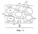
- Figure 1 is an illustration showing a physical diagram of a cleaning material for removing contamination from a semiconductor wafer, in accordance with one embodiment of the present invention.
- Figures 2A-2B are illustrations showing how the cleaning material functions to remove the contaminant from the wafer, in accordance with one embodiment of the present invention.
- Figure 3 is an illustration showing a flowchart of a method for removing contamination from a substrate, in accordance with one embodiment of the present invention.
- Figure 4 is a simplified schematic diagram illustrating a graph depicting the net interaction energy curve formed when subtracting the attraction curve from the repulsion curve in accordance with one embodiment of the invention.
- Figure 5 is a simplified schematic diagram illustrating an aggregate of surfactant molecules which may form the solid particles described herein, in accordance with one embodiment of the invention.
- Figure 6A is a simplified schematic diagram of a top view of a system for cleaning a substrate in accordance with one embodiment of the invention.
- Figure 6B is a simplified schematic diagram of a side view of the system depicted in Figure 6A for cleaning a substrate in accordance with one embodiment of the invention.
- a cleaning solution having a continuous phase and a dispersed phase is provided. Solid particles are disseminated throughout the continuous phase.
- the dispersed phase refers to either gas bubbles dispersed throughout the continuous phase, e.g., with reference to a foam, or liquid droplets dispersed throughout the continuous phase, e.g.
- the dispersed phase provides a vehicle to bring the solid particles proximate to the contaminant in order for the solid particles and the contaminant to interact to eventually remove the contaminant.
- FIG. 1 is an illustration showing a physical diagram of a cleaning material 101 for removing contamination 103 from a semiconductor wafer ("wafer") 105, in accordance with one embodiment of the present invention.
- the cleaning material 101 of the present invention includes a continuous liquid medium 107, solid components 109, and immiscible components 111.
- the solid components 109 and immiscible components 111 are dispersed within the continuous liquid medium 107.
- the continuous liquid medium 107 can be either aqueous or non-aqueous.
- the immiscible components 111 can be defined in either a gas phase, a liquid phase, a solid phase, or a combination of gas, liquid, and solid phases.
- the immiscible components 111 are defined as a mixture of immiscible components 111, wherein each immiscible component 111 within the mixture has either a common physical state or a different physical state.
- the physical states of immiscible components 111 within the mixture of immiscible components 111 can include a gas and a liquid, a gas and a solid, a liquid and a solid, or any combination of multiple gases, multiple liquids, and multiple solids.
- the immiscible components 111 are immiscible with respect to the continuous liquid medium 107.
- the immiscible components 111 are defined as gas bubbles within the continuous liquid medium 107.
- the immiscible components 111 are defined as liquid droplets within the continuous liquid medium 107.
- the solid components 109 are dispersed in suspension within the continuous liquid medium 107.
- the solid components 109 within the cleaning material 101 may possess physical properties representing essentially any sub-state within the solid phase, wherein the solid phase is defined as a phase other than liquid or gas.
- physical properties such as elasticity and plasticity can vary among different types of solid components 109 within the cleaning material 101.
- the solid components 109 can be defined as crystalline solids or non-crystalline solids. Regardless of their particular physical properties, the solid components 109 within the cleaning material 101 should be capable of avoiding adherence to the surface of wafer 105 when positioned in either close proximity to or contact with the surface of wafer 105.
- the mechanical properties of the solid components 109 should not cause damage to the wafer 105 surface during the cleaning process.
- the solid components 109 should be capable of establishing an interaction with the contaminant 103 material present on the wafer 105 surface when positioned in either close proximity or contact with the contaminant 103.
- the size and shape of the solid components 109 should be favorable for establishing the interaction between the solid components 109 and the contaminants 103.
- the solid components 109 within the cleaning material 101 should be capable of interacting with contaminants 103 on the wafer 105 while avoiding both adhesion and damage to the wafer 105.
- the solid components 109 should avoid dissolution in the liquid medium 107 and should have a surface functionality that enables dispersion throughout the liquid medium 107.
- chemical dispersants may be added to the liquid medium 107 to enable dispersion of the solid components 109.
- the solid components 109 may take one or more of several different forms.
- the solid components 109 may form aggregates, colloids, gels, coalesced spheres, or essentially any other type of agglutination, coagulation, flocculation, agglomeration, or coalescence.
- the exemplary list solid component 109 forms identified above is not intended to represent an inclusive list.
- the solid components 109 may take a form not specifically identified herein. Therefore, the point to understand is that the solid components 109 can be defined as essentially any solid material capable of functioning in the manner previously described with respect to their interaction with the wafer 105 and the contaminants 103.
- Some exemplary solid components 109 include aliphatic acids, carboxylic acids, paraffin, wax, polymers, polystyrene, polypeptides, and other visco-elastic materials.
- the solid component 109 material should be present at a concentration that exceeds its solubility limit within the liquid medium 107.
- the cleaning effectiveness associated with a particular solid component 109 material may vary as a function of temperature, pH, and other environmental conditions.
- the aliphatic acids represent essentially any acid defined by organic compounds in which carbon atoms form open chains.
- a fatty acid is an example of an aliphatic acid that can be used as the solid components 109 within the cleaning material 101.
- fatty acids that may be used as the solid components 109 include lauric, palmitic, stearic, oleic, linoleic, linolenic, arachidonic, gadoleic, eurcic, butyric, caproic, caprylic, myristic, margaric, behenic, lignoseric, myristoleic, palmitoleic, nervanic, parinaric, timnodonic, brassic, clupanodonic acid, lignoceric acid, cerotic acid, and mixtures thereof, among others.
- the solid components 109 can represent a mixture of fatty acids defined by various carbon chain lengths extending from C-1 to about C-26.
- Carboxylic acids are defined by essentially any organic acid that includes one or more carboxyl groups (COOH).
- the carboxylic acids can include mixtures of various carbon chain lengths extending from C-1 through about C-100.
- the carboxylic acids can include other functional groups such as but not limited to methyl, vinyl, alkyne, amide, primary amine, secondary amine, tertiary amine, azo, nitrile, nitro, nitroso, pyridyl, carboxyl, peroxy, aldehyde, ketone, primary imine, secondary imine, ether, ester, halogen, isocyanate, isothiocyanate, phenyl, benzyl, phosphodiester, sulfhydryl, but still maintaining insolubility in the liquid medium 107.
- functional groups such as but not limited to methyl, vinyl, alkyne, amide, primary amine, secondary amine, tertiary amine, azo, nitrile, nitro, nitroso, pyridyl, carboxyl, peroxy, aldehyde, ketone, primary imine, secondary imine, ether, ester, halogen, isocyanate
- a dispersant material to the liquid medium 107 may be required to enable a particular type of solid component 109, such as a fatty acid, to disperse throughout the liquid medium 107.
- a base can be added to the liquid medium 107 to enable suspension of solid components 109 formed from materials such as carboxylic acid or stearic acid that are present in less than stoichiometric quantities.
- the base is Ammonium Hydroxide, however, any commercially available base may be used with the embodiments described herein.
- the surface functionality of the solid component 109 materials can be influenced by the inclusion of moieties that are miscible with the liquid medium 107, such as carboxylate, phosphate, sulfate groups, polyol groups, ethylene oxide, etc.
- moieties that are miscible with the liquid medium 107 such as carboxylate, phosphate, sulfate groups, polyol groups, ethylene oxide, etc.
- the solid components 109 should be dispersible in a substantially uniform manner throughout the liquid medium 107 such that the solid components 109 avoid clumping together into a form that cannot be forced to interact with the contaminants 103 present on the wafer 105.
- the continuous liquid medium 107 can be either aqueous or non-aqueous.
- an aqueous liquid medium 107 can be defined by de-ionized water in one embodiment.
- a non-aqueous liquid medium 107 can be defined by a hydrocarbon, a fluorocarbon, a mineral oil, or an alcohol, among others. Irrespective of whether the liquid medium 107 is aqueous or non-aqueous, it should be understood that the liquid medium 107 can be modified to include ionic or non-ionic solvents and other chemical additives.
- the chemical additives to the liquid medium 107 can include any combination of co-solvents, pH modifiers, chelating agents, polar solvents, surfactants, ammonia hydroxide, hydrogen peroxide, hydrofluoric acid, tetramethylammonium hydroxide, and theology modifiers such as polymers, particulates, and polypeptides.
- the immiscible components 111 within the cleaning material 101 can be defined in either the gas phase, the liquid phase, the solid phase, or a combination thereof.
- the immiscible components 111 are defined as gas bubbles dispersed throughout the continuous liquid medium 107.
- the gas bubbles are defined to occupy 5% to 99.9% of the cleaning material 101 by volume.
- the gas bubbles are defined to occupy 50% to 95% of the cleaning material 101 by weight.
- the gas defining the immiscible components 111 can be either inert, e.g., N 2 , Ar, etc., or reactive, e.g., O 2 , O 3 , H 2 O 2 , air, H 2 , NH 3 , HF, etc.
- the immiscible components 111 are defined as liquid droplets dispersed throughout the continuous liquid medium 107, wherein the liquid droplets are immiscible within the liquid medium 107.
- the liquid defining the immiscible components 111 can be either inert or reactive.
- a low-molecular weight alkane e.g., pentane, hexane, heptane, octane, nonane, decane, or mineral oil
- oil soluble surface modifiers may be used as a reactive liquid for defining the immiscible components 111.
- a downward force is exerted on the solid components 109 within the liquid medium 107 such that the solid components 109 are brought within close proximity or contact with the contaminants 103 on the wafer 105.
- the immiscible components 111 within the cleaning material 101 provide the mechanism by which the downward force is exerted on the solid components 109.
- an interaction is established between the solid component 109 and the contaminant 103.
- the interaction between the solid component 109 and the contaminant 103 is sufficient to overcome an adhesive force between the contaminant 103 and the wafer 105, as well as any repulsive forces between the solid component 109 and the contaminant.
- the contaminant 103 that interacted with the solid component 109 is also moved away from the wafer 105, i.e., the contaminant 103 is cleaned from the wafer 105.
- Figures 2A-2B are illustrations showing how the cleaning material 101 functions to remove the contaminant 103 from the wafer 105, in accordance with one embodiment of the present invention. It should be understood that the cleaning material 101 depicted in Figures 2A-2B possesses the same characteristics as previously described with respect to Figure 1. As shown in Figure 2A, within the liquid medium 107 of the cleaning material 101, the solid component 109 is interposed between the contaminant 103 and the immiscible component 111. The immiscible component 111 within the liquid medium 107, whether gas bubbles or liquid droplets, has an associated surface tension.
- the immiscible component 111 when the immiscible component 111 is pressed downward against the solid component 109, the immiscible component 111 becomes deformed and exerts a downward force (F) on the solid component 109.
- This downward force (F), or a normal component of F, serves to move the solid component 109 toward the wafer 105 and contaminant 103 thereon.
- the interaction between the solid component 109 and contaminant 103 occurs when the solid component 109 is forced sufficiently close to the contaminant 103. In one embodiment, this distance may be within about 10 nanometers.
- the interaction between the solid component 109 and contaminant 103 occurs when the solid component 109 actually contacts the contaminant 103. This interaction may also be referred to as solid component 109 engaging contaminant 103.
- the interaction force between the solid component 109 and the contaminant 103 is stronger than the force connecting the contaminant 103 to the wafer 105. Additionally, in an embodiment where the solid component 109 binds with the contaminant 103, a force used to move the solid component 109 away from the wafer 105 is stronger than the force connecting the contaminant 103 to the wafer 105. Therefore, as depicted in Figure 2B, when the solid component 109 is moved away from the wafer 105, the contaminant 103 bound to the solid component 109 is also moved away from the wafer 105.
- the solid components 109 interact with the contamination 103 to affect the cleaning process, contamination 103 removal across the wafer 105 will be dependent on how well the solid components 109 are distributed across the wafer 105.
- the solid components 109 will be so well distributed that essentially every contaminant 103 on the wafer 105 will be in proximity to at least one solid component 109.
- one solid component 109 may come in contact with or interact with more than one contaminant 103, either in a simultaneous manner or in a sequential manner.
- solid component 109 may be a mixture of different components as opposed to all the same component.
- the cleaning solution is capable of being designed for a specific purpose, i.e., targeting a specific contaminant, or the cleaning solution can have a broad spectrum of contaminant targets where multiple solid components are provided.
- Interaction between the solid component 109 and the contaminant 103 can be established through one or more mechanisms including adhesion, collision, and attractive forces, among others.
- Adhesion between the solid component 109 and contaminant 103 can be established through chemical interaction and/or physical interaction.
- chemical interaction causes a glue-like effect to occur between the solid component 109 and the contaminant 103.
- physical interaction between the solid component 109 and the contaminant 103 is facilitated by the mechanical properties of the solid component 109.
- the solid component 109 can be malleable such that when pressed against the contaminant 103, the contaminant 103 becomes imprinted within the malleable solid component 109.
- the contaminant 103 can become entangled in a network of solid components 109.
- mechanical stresses can be transferred through the network of solid components 109 to the contaminant 103, thus providing the mechanical force necessary for removal of the contaminant 103 from the wafer 105.
- Deformation of the solid component 109 due to imprinting by the contaminant 103 creates a mechanical linkage between the solid component 109 and the contaminant 103.
- a surface topography of the contaminant 103 may be such that as the contaminant 103 is pressed into the solid component 109, portions of the solid component 109 material enters regions within the surface topography of the contaminant 103 from which the solid component 109 material cannot easily escape, thereby creating a locking mechanism.
- a vacuum force can be established to resist removal of the contaminant 103 from the solid component 109.
- energy transferred from the solid component 109 to the contaminant 103 through direct or indirect contact may cause the contaminant 103 to be dislodged from the wafer 105.
- the solid component 109 may be softer or harder than the contaminant 103. If the solid component 109 is softer than the contaminant 103, greater deformation of the solid component 109 is likely to occur during the collision, resulting in less transfer of kinetic energy for dislodging the contaminant 103 from the wafer 105. However, in the case where the solid component 109 is softer than the contaminant 103, the adhesive connection between the solid component 109 and the contaminant 103 may be stronger.
- the solid component 109 is at least as hard as the contaminant 103, a substantially complete transfer of energy can occur between the solid component 109 and the contaminant 103, thus increasing the force that serves to dislodge the contaminant 103 from the wafer 105.
- interaction forces that rely on deformation of the solid component 109 may be reduced. It should be appreciated that physical properties and relative velocities associated with the solid component 109 and the contaminant 103 will influence the collision interaction there between.
- interaction between the solid component 109 and contaminant 103 can result from electrostatic attraction.
- the solid component 109 and the contaminant 103 have opposite surface charges they will be electrically attracted to each other. It is possible that the electrostatic attraction between the solid component 109 and the contaminant 103 can be sufficient to overcome the force connecting the contaminant 103 to the wafer 105.
- an electrostatic repulsion may exist between the solid component 109 and the contaminant 103.
- both the solid component 109 and the contaminant 103 can have either a negative surface charge or a positive surface charge. If the solid component 109 and the contaminant 103 can be brought into close enough proximity, the electrostatic repulsion there between can be overcome through van der Waals attraction. The force applied by the immiscible component 111 to the solid component 109 may be sufficient to overcome the electrostatic repulsion such that van der Waals attractive forces are established between the solid component 109 and the contaminant 103. Further details of this embodiment, are provided with reference to Figure 4.
- the pH of the liquid medium 107 can be adjusted to compensate for surface charges present on one or both of the solid component 109 and contaminant 103, such that the electrostatic repulsion there between is reduced to facilitate interaction, or so that either the solid component or the contamination exhibit surface charge reversal relative to the other resulting in electrostatic attraction.
- Figure 3 is an illustration showing a flowchart of a method for removing contamination from a substrate, in accordance with one embodiment of the present invention.
- the substrate referenced in the method of Figure 3 can represent a semiconductor wafer or any other type of substrate from which contaminants associated with a semiconductor fabrication process need to be removed.
- the contaminants referenced in the method of Figure 3 can represent essentially any type of contaminant associated with the semiconductor wafer fabrication process, including but not limited to particulate contamination, trace metal contamination, organic contamination, photoresist debris, contamination from wafer handling equipment, and wafer backside particulate contamination.
- the method of Figure 3 includes an operation 301 for disposing a cleaning material over a substrate, wherein the cleaning material includes solid components dispersed within a liquid medium.
- the cleaning material referenced in the method of Figure 3 is the same as previously described with respect to Figures 1, 2A, and 2B. Therefore, the solid components within the cleaning material are dispersed in suspension within the liquid medium. Also, the solid components are defined to avoid damaging the substrate and to avoid adherence to the substrate. In one embodiment, the solid components are defined as crystalline solids. In another embodiment, the solid components are defined as non-crystalline solids. In yet another embodiment, the solid components are represented as a combination of crystalline and non-crystalline solids. Additionally, in various embodiments, the liquid medium can be either aqueous or non-aqueous.
- the method also includes an operation 303 for applying a force to a solid component to bring the solid component within proximity to a contaminant present on the substrate, such that an interaction is established between the solid component and the contaminant.
- immiscible components are provided within the cleaning material to apply the force to the solid component necessary to bring the solid component within proximity to the contaminant.
- the method can include an operation for controlling the immiscible components to apply a controlled amount of force to the solid component.
- the immiscible components can be defined as gas bubbles or immiscible liquid droplets within the liquid medium. Additionally, the immiscible components can be represented as a combination of gas bubbles and immiscible liquid droplets within the liquid medium.
- the immiscible components are defined within the liquid medium prior to disposing the cleaning material over the substrate.
- the method can include an operation to form the immiscible components in-situ following disposition of the cleaning material over the substrate.
- the immiscible components can be formed from a dissolved gas within the liquid medium upon a decrease in ambient pressure relative to the cleaning material. It should be appreciated that formation of the immiscible components in situ may enhance the contamination removal process.
- gravity serves to pull the solid components toward the substrate prior to formation of the immiscible components. Then, the ambient pressure is reduced such that gas previously dissolved within the liquid medium comes out of solution to form gas bubbles.
- the interaction between the solid component and the contaminant can be established by adhesive forces, collision forces, attractive forces, or a combination thereof.
- the method can include an operation for modifying a chemistry of the liquid medium to enhance interaction between the solid component and the contaminant.
- the pH of the liquid medium can be modified to cancel surface charges on one or both of the solid component and contaminant such that electrostatic repulsion is reduced.
- the method can include an operation for controlling a temperature of the cleaning material to enhance interaction between the solid component and the contaminant.
- the temperature of the cleaning material can be controlled to control the properties of the solid component. For example, at a higher temperature the solid component may be more malleable such that it conforms better when pressed against the contaminant. Then, once the solid component is pressed and conformed to the contaminant, the temperature is lowered to make the solid component less malleable to better hold its conformal shape relative to the contaminant, thus effectively locking the solid component and contaminant together.
- the temperature may also be used to control the solubility and therefore the concentration of the solid components. For example, at higher temperatures the solid component may be more likely to dissolve in the liquid medium.
- the temperature may also be used to control and/or enable formation of solid components in-situ on the wafer from liquid-liquid suspension.
- the method can include an operation for precipitating solids dissolved within the continuous liquid medium.
- This precipitation operation can be accomplished by dissolving the solids into a solvent and then adding a component that is miscible with the solvent but that does not dissolve the solid. Addition of the component that is miscible with the solvent but that does not dissolve the solid causes the precipitation of a solid component.
- the method further includes an operation 305 for moving the solid component away from the substrate such that the contaminant that interacted with the solid component is removed from the substrate.
- the method includes an operation for controlling a flow rate of the cleaning material over the substrate to control or enhance movement of the solid component and/or contaminant away from the substrate.
- Figure 4 is a simplified schematic diagram illustrating a graph depicting the net interaction energy curve formed when subtracting the attraction curve from the repulsion curve in accordance with one embodiment of the invention.
- electrical repulsion is depicted by line 401 while Van der Waals attraction is depicted by line 403.
- the Y-axis represents energy with repulsive energy being shown above the X-axis and attractive energy illustrated below the X-axis.
- the X-axis represents distance between particles.
- the net interaction energy is depicted by curve 405 and is simply the sum of lines 401 and 403. Region 407 may be referred to as an energy trap, while region 409 may be referred to as an energy barrier.
- electrostatic repulsion becomes significant when two particles/colloids approach each other and their double layers begin to interfere. Energy is required to overcome this repulsion. In one embodiment described herein, this energy may be provided by the cleaning solution, or more specifically, an immiscible component of the cleaning solution, as described above.
- the electrostatic repulsion curve 401 indicates the energy that must be overcome if the particles are to be forced together. It should be appreciated that the maximum energy is related to the surface potential and the zeta potential.
- Van der Waals attraction is actually the result of forces between individual molecules in each particle/colloid.
- the effect is additive; that is, one molecule of the first particle/colloid has a Van der Waals attraction to each molecule in the second colloid. This is repeated for each molecule in the first particle/colloid, and the total force is the sum of all of these.
- the attractive energy curve 403 is used to indicate the variation in Van der Walls force with distance between the particles. At each distance on the X axis the smaller value is subtracted from the larger value to get the net energy. The net value is then plotted, above if repulsive and below if attractive, and a curve is formed. If there is a repulsive section, then the point of maximum repulsive energy is called the energy barrier 409.
- the height of energy barrier 409 indicates how stable the system is. In order to agglomerate, two particles on a collision course must have sufficient kinetic energy due to their velocity mass to jump over this barrier. If the barrier is cleared, then the net interaction is all attractive and as a result, the particles agglomerate.
- This inner region 407 is referred to as an energy trap since the particles/colloids can be considered to be trapped together by Van der Waals forces.
- the environmental conditions for a colloidal solution may be altered to either increase or decrease the energy barrier, depending on the particular application. The conditions that can be altered include changing ionic strength, changing pH, or adding surface-active materials to directly affect the charge of the colloid. In each case, zeta potential measurements can indicate the impact of the alternation on overall stability.
- FIG. 5 is a simplified schematic diagram illustrating an aggregate/assembly of surfactant molecules, which may form the solid particles described herein, in accordance with one embodiment of the invention.
- the aggregate/assembly of surfactant molecules is usually of a globular shape, but other geometrical shapes are also possible, e.g., ellipsoid, cylinder, vesicles, lamellae, etc.
- the aggregate/assembly of surfactant molecules may also be referred to a micelle.
- Micelles form when a concentration of surfactant is greater than the critical micellar concentration (CMC), and the temperature of the system is greater than the critical micellar temperature.
- CMC critical micellar concentration
- surfactants are chemicals that contain both hydrophobic groups, e.g. long hydrocarbon chains, and hydrophilic groups, e.g., ionic or polar groups.
- hydrophobic groups e.g. long hydrocarbon chains
- hydrophilic groups e.g., ionic or polar groups.
- the core 501 of the micelle consists of the hydrophobic portion of the molecules, while the hydrophilic portions 503 remain on the surface of the molecule so that they can maintain favorable contact with water.
- the electric charge of the ionic heads is neutralized by the oppositely charged ions (counter ions) located in the layer around the micelle, to fulfill the condition of electroneutrality.
- the hydrophilic groups will form the core of the micelle, and the hydrophobic groups remain on the surface of the micelle, i.e. a reverse micelle.
- the micelle 109 represents an agglomeration/assembly of surface-active molecules that may function as the solid components 109.
- solid components may be formed through other techniques mentioned above.
- Example 1 provides a technique requiring melting of the fatty acid and Example 2 pre-mills the fatty acid to achieve a desirable particle distribution, thereby eliminating the need to melt the fatty acid.
- Example 3 provides a technique where dissolved fatty acids are precipitated from a solvent to achieve a desirable particle distribution.
- a non-polar solvent may be used in place of water and a non-polar or a polar compound may be mixed/dissolved in the non-polar solvent.
- Solid Stearic acid (about 0.1% by weight to about 10% by weight) is heated above 70 degrees Celsius and added to the heated water.
- the water-stearic acid mixture is stirred at a rate so that the immiscible stearic acid is dispersed or emulsified within the continuous water phase.
- Ionization of the stearic acid is initiated by adding a base to bring the pH up to a point where about 50% of the carboxylic acid is dissociated, i.e., the dissociation constant (pK a ) is about 50%. This occurs at a pH of about 10.2.
- An exemplary base added to the solution to bring the pH up is ammonium hydroxide (NH 4 OH).
- the concentration of the NH 4 OH can range between 0.25% and 10% by weight.
- the stearic acid/water/NH 4 OH mixture is stirred for an additional 20 minutes to form a homogeneous solution.
- the solution cools to ambient and sits for 10 hours and over time a precipitate forms, i.e., the solid components.
- air can be entrained into the mixture but it is not necessary.
- the size distribution of these precipitate particles (solid components) is between about 50 nanometers and 5000 micrometers.
- the granular stearic acid is milled to a particle size distribution between about 0.5 and about 5000 micrometers. Any commercially available powder mill may achieve this size distribution.
- the milled Stearic acid (about 0.1% by weight to about 10% by weight) in granular form is added to water while agitating the solution.
- the solution can be agitated by shaking, stirring, rotating, etc.
- Dissociation of the stearic acid is initiated by adding a base to bring the pH up to a point where about 50% of the carboxylic acid is dissociated, i.e., the pK a is about 50%. This occurs at a pH of above 10.2.
- An exemplary base added to the solution to bring the pH up is ammonium hydroxide (NH 4 OH).
- the concentration of the NH 4 OH can range between 0.5% and 10% by weight. Adding NH 4 OH to the aqueous solution while agitating the solution disperses the solid stearic acid component into the continuous water phase. The ionized solid stearic acid component remains suspended within the continuous aqueous phase without agitation. The size distribution of these particles is between about 0.5 and about 5,000 micrometers.
- a mixture of stearic and palmitic acids is dissolved in isopropanol (IPA) while agitating the solution.
- the concentration of dissolved fatty acids in the solvent can range from about 2% to 20% by weight. Heating of the solvent below the boiling point of the solvent or addition of another organic solvent or solvents, such as acetone or benzene, can improve solubility of the fatty acid.
- the solution can be agitated by shaking, stirring, rotating, etc. Once the dissolution is complete, the remaining solids can be removed by filtration or centrifugation.
- the solid-free solution is next mixed with water (a non-solvent for the fatty acid) to precipitate a fatty-acid solid.
- the precipitated fatty acid becomes suspended in solution with the size distribution in the range between 0.5 and 5,000 microns.
- Ionization of the stearic acid can be initiated by adding a base to bring the pH up to 10.2 or higher.
- An exemplary base added to the solution to bring the pH up is ammonium hydroxide (NH 4 OH).
- the concentration of the NH 4 OH can range between 0.25% and 10% by weight.
- FIG. 6A is a simplified schematic diagram of a top view of a system for cleaning a substrate in accordance with one embodiment of the invention.
- Substrate 601 moves in a linear direction toward the cleaning head.
- the cleaning head includes a portion 603 configured to provide the cleaning solution.
- the cleaning solution may be in the form of a foam or an emulsion.
- the cleaning solution is delivered from a reservoir, which may or may not be pressurized. If the reservoir is pressurized, the cleaning solution may be aerated and develop into a foam prior to being delivered to the cleaning head. Where the reservoir is not pressurized, the cleaning solution may be pumped or delivered through other commonly known means. In another embodiment, an emulsion may be delivered to the cleaning head from an off-line reservoir.
- Portion 605 includes a rinse chemistry, such as deionized water (DIW) or some other cleaning chemistry commonly used for the particular application.
- Portion 607 of the cleaning head provides the drying capability and may utilize an inert gas, such as Nitrogen and/or a low vapor pressure liquid such as isopropyl alcohol (IPA).
- an inert gas such as Nitrogen and/or a low vapor pressure liquid such as isopropyl alcohol (IPA).
- IPA isopropyl alcohol
- portions 605 and 607 which are located downstream from the cleaning portion 603 in one embodiment, may provide a cleaning meniscus and may be the proximity cleaning head owned by the assignee and further described in the cross referenced applications listed below.
- substrate 601 may rotate and/or rotate and move linearly.
- the cleaning head may move over substrate 601 while the substrate is stationary or also moving.
- the cleaning may be performed in a cleaning compartment where a single wafer is deposited and the cleaning solution is applied.
- a tool providing sequential compartments for each of portion 603, 605, and 607 may be provided.
- the cleaning head may include two portions 603 for cleaning solution with portion 605 sandwiched in between the two portions 603.
- Figure 6B is a side view of the cleaning head of Figure 6A.
- Cleaning fluid is supplied to portion 603 as mentioned above.
- DIW and/or some other suitable cleaning chemistry may be provided to portion 605.
- Vacuum may optionally be provided to portion 605 also to provide a meniscus as discussed in the cross-referenced application below in more detail.
- An inert gas and/or IPA are provided to portion 607.
- Figures 6A and 6B are illustrated with respect to a semiconductor substrate, the embodiments may be extended to flat panel displays, solar cells, memory devices, etc.
- the continuous phase or dispersant phase includes those compounds that are considered part of the hydrocarbon family.
- Hydrocarbon compounds are those compounds that comprise carbon and hydrogen. It should be understood that a majority of hydrocarbon compounds are non-polar, and therefore less polar than water; however, there are a few hydrocarbon compounds that could be considered to be as polar or more polar than water. Hydrocarbon compounds are generally broken down into three classes: aliphatic, cyclic and aromatic. Aliphatic hydrocarbon compounds may comprise both straight-chain compounds and compounds that are branched and possibly cross-linked, however, aliphatic hydrocarbon compounds are not considered cyclic.
- Cyclic hydrocarbon compounds are those compounds that comprise at least three carbon atoms oriented in a ring structure with properties similar to aliphatic hydrocarbon compounds.
- Aromatic hydrocarbon solvents are those compounds that comprise generally three or more unsaturated bonds with a single ring or multiple rings attached by a common bond and/or multiple rings fused together.
- Contemplated hydrocarbon compounds include toluene, xylene, p-xylene, m-xylene, mesitylene, solvent naphtha H, solvent naphtha A, alkanes, such as pentane, hexane, isohexane, heptane, nonane, octane, dodecane, 2-methylbutane, hexadecane, tridecane, pentadecane, cyclopentane, 2,2,4-trimethylpentane, petroleum ethers, halogenated hydrocarbons, such as chlorinated hydrocarbons, fluorinated hydrocarbons, nitrated hydrocarbons, benzene, 1,2-dimethylbenzene, 1,2,4-trimethylbenzene, mineral spirits, kerosine, isobutylbenzene, methylnaphthalene, ethyltoluene, ligroine.
- the continuous phase or dispersant phase may comprise those compounds that are not considered part of the hydrocarbon family of compounds, such as ketones, which include fluorinated ketones, e.g., acetone, diethyl ketone, methyl ethyl ketone and the like, alcohols, which include fluorinated alcohols, esters, which include fluorinated esters, fluorinated and non-fluorinated carbonate-based compounds, such as propylene carbonate and the like, ethers, which include fluorinated ethers, and amines, which include fluorinated amines.
- the continuous phase or dispersant phase may comprise a combination of any of the compounds mentioned herein.
- the continuous phase is a polar solvent such as water
- the above listed non-polar compounds may be used in the dispersed phase, as the non-polar compounds are typically immiscible with polar solvents.
- the non-polar compounds may be used in the continuous phase for certain applications and the polar compounds may be used for the dispersed phase.
- Exemplary polar solvents besides water include acetic acid, formic acid, methanol, ethanol, n-propanol, n-butanol, isopropanol, acetone, acetonitrile, dimethylformamide, dimethyl sulfoxide, and mixtures thereof. It should be appreciate that the lists of materials provided herein are meant to be exemplary and not limiting.
- the present invention has been described in the context of removing contaminants from a semiconductor wafer, it should be understood that the previously described principles and techniques of the present invention can be equally applied to cleaning surfaces other than semiconductor wafers.
- the present invention can be used to clean any equipment surface used in semiconductor manufacturing, wherein any equipment surface refers to any surface that is in environmental communication with the wafer, e.g., shares air space with the wafer.
- the present invention can also be used in other technology areas where contamination removal is important.
- the present invention can be used to remove contamination on parts used in the space program, or other high technology areas such as surface science, energy, optics, microelectronics, MEMS, flat-panel processing, solar cells, memory devices, etc.
- the aforementioned listing of exemplary areas where the present invention may be used is not intended to represent an inclusive listing.
- the wafer as used in the exemplary description herein can be generalized to represent essentially any other structure, such as a substrate, a part, a panel, etc.
Landscapes
- Chemical & Material Sciences (AREA)
- Organic Chemistry (AREA)
- Engineering & Computer Science (AREA)
- Chemical Kinetics & Catalysis (AREA)
- Oil, Petroleum & Natural Gas (AREA)
- Wood Science & Technology (AREA)
- Life Sciences & Earth Sciences (AREA)
- Health & Medical Sciences (AREA)
- Emergency Medicine (AREA)
- General Chemical & Material Sciences (AREA)
- Materials Engineering (AREA)
- Mechanical Engineering (AREA)
- Metallurgy (AREA)
- Cleaning Or Drying Semiconductors (AREA)
Priority Applications (1)
| Application Number | Priority Date | Filing Date | Title |
|---|---|---|---|
| EP11192481A EP2428557A1 (de) | 2005-12-30 | 2006-11-29 | Reinigungslösung |
Applications Claiming Priority (2)
| Application Number | Priority Date | Filing Date | Title |
|---|---|---|---|
| US75537705P | 2005-12-30 | 2005-12-30 | |
| US11/346,894 US7737097B2 (en) | 2003-06-27 | 2006-02-03 | Method for removing contamination from a substrate and for making a cleaning solution |
Publications (2)
| Publication Number | Publication Date |
|---|---|
| EP1803504A2 true EP1803504A2 (de) | 2007-07-04 |
| EP1803504A3 EP1803504A3 (de) | 2011-10-12 |
Family
ID=37963651
Family Applications (1)
| Application Number | Title | Priority Date | Filing Date |
|---|---|---|---|
| EP06256120A Withdrawn EP1803504A3 (de) | 2005-12-30 | 2006-11-29 | Verfahren zum Entfernen von Verunreinigungen von einem Substrat und Verfahren zur Herstellung einer Reinigungslösung |
Country Status (7)
| Country | Link |
|---|---|
| US (2) | US7737097B2 (de) |
| EP (1) | EP1803504A3 (de) |
| JP (1) | JP5219366B2 (de) |
| KR (2) | KR20070072374A (de) |
| MY (1) | MY150857A (de) |
| SG (1) | SG133491A1 (de) |
| TW (1) | TWI332421B (de) |
Cited By (2)
| Publication number | Priority date | Publication date | Assignee | Title |
|---|---|---|---|---|
| WO2010103416A3 (en) * | 2009-03-10 | 2010-12-09 | Lam Research Corporation | Method of particle contaminant removal |
| TWI871058B (zh) * | 2023-07-14 | 2025-01-21 | 帝科有限公司 | 顯影液中膠體監控方法、顯影設備及化垢組合物 |
Families Citing this family (24)
| Publication number | Priority date | Publication date | Assignee | Title |
|---|---|---|---|---|
| US7696141B2 (en) * | 2003-06-27 | 2010-04-13 | Lam Research Corporation | Cleaning compound and method and system for using the cleaning compound |
| US7799141B2 (en) * | 2003-06-27 | 2010-09-21 | Lam Research Corporation | Method and system for using a two-phases substrate cleaning compound |
| US7737097B2 (en) * | 2003-06-27 | 2010-06-15 | Lam Research Corporation | Method for removing contamination from a substrate and for making a cleaning solution |
| US9236279B2 (en) * | 2003-06-27 | 2016-01-12 | Lam Research Corporation | Method of dielectric film treatment |
| US7862662B2 (en) * | 2005-12-30 | 2011-01-04 | Lam Research Corporation | Method and material for cleaning a substrate |
| US8480810B2 (en) * | 2005-12-30 | 2013-07-09 | Lam Research Corporation | Method and apparatus for particle removal |
| US20080245390A1 (en) * | 2007-04-03 | 2008-10-09 | Lam Research Corporation | Method for cleaning semiconductor wafer surfaces by applying periodic shear stress to the cleaning solution |
| US8388762B2 (en) * | 2007-05-02 | 2013-03-05 | Lam Research Corporation | Substrate cleaning technique employing multi-phase solution |
| US8084406B2 (en) * | 2007-12-14 | 2011-12-27 | Lam Research Corporation | Apparatus for particle removal by single-phase and two-phase media |
| US8105997B2 (en) * | 2008-11-07 | 2012-01-31 | Lam Research Corporation | Composition and application of a two-phase contaminant removal medium |
| JP2010192673A (ja) * | 2009-02-18 | 2010-09-02 | Tokyo Electron Ltd | 基板洗浄方法、基板洗浄装置、制御プログラム及びコンピュータ読取可能な記憶媒体 |
| US8845812B2 (en) * | 2009-06-12 | 2014-09-30 | Micron Technology, Inc. | Method for contamination removal using magnetic particles |
| US8367594B2 (en) | 2009-06-24 | 2013-02-05 | Lam Research Corporation | Damage free, high-efficiency, particle removal cleaner comprising polyvinyl alcohol particles |
| US8765653B2 (en) * | 2009-07-07 | 2014-07-01 | Air Products And Chemicals, Inc. | Formulations and method for post-CMP cleaning |
| KR101172861B1 (ko) | 2010-02-26 | 2012-08-09 | 삼성전기주식회사 | 금속 나노입자의 세정방법 |
| US8609602B2 (en) | 2010-07-14 | 2013-12-17 | Anatrace Products, Llc | Cleaning solution |
| CA2856196C (en) | 2011-12-06 | 2020-09-01 | Masco Corporation Of Indiana | Ozone distribution in a faucet |
| JP2015028971A (ja) * | 2013-07-30 | 2015-02-12 | パナソニックIpマネジメント株式会社 | ウエハ洗浄装置およびウエハ洗浄方法 |
| JP2015207712A (ja) | 2014-04-22 | 2015-11-19 | 三菱電機株式会社 | 洗浄液、洗浄設備、および実装基板の洗浄方法 |
| JP6498573B2 (ja) * | 2015-09-15 | 2019-04-10 | 東京エレクトロン株式会社 | 基板処理方法、基板処理装置および記憶媒体 |
| WO2017112795A1 (en) | 2015-12-21 | 2017-06-29 | Delta Faucet Company | Fluid delivery system including a disinfectant device |
| KR102464636B1 (ko) * | 2018-02-07 | 2022-11-09 | 삼성전자주식회사 | 세정 조성물, 세정 장치, 및 그를 이용한 반도체 소자의 제조 방법 |
| US20240316598A1 (en) * | 2023-03-20 | 2024-09-26 | Applied Materials, Inc. | Compression gap control for pad-based chemical buff post cmp cleaning |
| CN119060797A (zh) * | 2024-08-26 | 2024-12-03 | 熠铎科技(苏州)有限公司 | 一种晶圆玻璃载片坯料酸洗液及其制备方法和设备 |
Family Cites Families (163)
| Publication number | Priority date | Publication date | Assignee | Title |
|---|---|---|---|---|
| GB553679A (en) | 1941-11-28 | 1943-06-01 | Ellis Clayton | A process for the preparation of a cleansing agent and the application thereof |
| US2537667A (en) | 1944-08-24 | 1951-01-09 | Monsanto Chemicals | Waterproofing of fibrous products |
| NL251243A (de) * | 1959-05-04 | |||
| US3212762A (en) | 1960-05-23 | 1965-10-19 | Dow Chemical Co | Foam generator |
| US3436262A (en) * | 1964-09-25 | 1969-04-01 | Dow Chemical Co | Cleaning by foam contact,and foam regeneration method |
| US3617095A (en) | 1967-10-18 | 1971-11-02 | Petrolite Corp | Method of transporting bulk solids |
| NL169612C (nl) | 1971-03-08 | 1982-08-02 | Minnesota Mining & Mfg | Werkwijze voor het bereiden van een preparaat voor het zowel reinigen als water- en olieafstotend maken van een substraat. |
| GB1427341A (en) | 1972-05-22 | 1976-03-10 | Unilever Ltd | Liquid soap product |
| US3978176A (en) * | 1972-09-05 | 1976-08-31 | Minnesota Mining And Manufacturing Company | Sparger |
| GB1507472A (en) * | 1974-05-02 | 1978-04-12 | Bunker Ramo | Foamable coating remover composition |
| GB1447435A (en) | 1974-06-03 | 1976-08-25 | Ferrara P J Barnes C A Gordon | Soap composition and process of producing such |
| US4156619A (en) * | 1975-06-11 | 1979-05-29 | Wacker-Chemitronic Gesellschaft Fur Elektronik-Grundstoffe Mbh | Process for cleaning semi-conductor discs |
| US4133773A (en) * | 1977-07-28 | 1979-01-09 | The Dow Chemical Company | Apparatus for making foamed cleaning solutions and method of operation |
| DE2823002B2 (de) * | 1978-05-26 | 1981-06-04 | Chemische Werke München Otto Bärlocher GmbH, 8000 München | Verfahren zur Herstellung von Metallseifengranulat |
| US4238244A (en) | 1978-10-10 | 1980-12-09 | Halliburton Company | Method of removing deposits from surfaces with a gas agitated cleaning liquid |
| US4387040A (en) * | 1981-09-30 | 1983-06-07 | Colgate-Palmolive Company | Liquid toilet soap |
| US4838289A (en) * | 1982-08-03 | 1989-06-13 | Texas Instruments Incorporated | Apparatus and method for edge cleaning |
| US4911761A (en) * | 1984-05-21 | 1990-03-27 | Cfm Technologies Research Associates | Process and apparatus for drying surfaces |
| HU200703B (en) * | 1986-07-08 | 1990-08-28 | Kohlensaeurewerk Deutschland | Method for drying vegetal or animal materials |
| NL8601939A (nl) | 1986-07-28 | 1988-02-16 | Philips Nv | Werkwijze voor het verwijderen van ongewenste deeltjes van een oppervlak van een substraat. |
| US4817652A (en) * | 1987-03-26 | 1989-04-04 | Regents Of The University Of Minnesota | System for surface and fluid cleaning |
| US4962776A (en) | 1987-03-26 | 1990-10-16 | Regents Of The University Of Minnesota | Process for surface and fluid cleaning |
| US4849027A (en) * | 1987-04-16 | 1989-07-18 | Simmons Bobby G | Method for recycling foamed solvents |
| US4753747A (en) * | 1987-05-12 | 1988-06-28 | Colgate-Palmolive Co. | Process of neutralizing mono-carboxylic acid |
| US5105556A (en) * | 1987-08-12 | 1992-04-21 | Hitachi, Ltd. | Vapor washing process and apparatus |
| US5000796A (en) * | 1988-02-23 | 1991-03-19 | Eastman Kodak Company | Anisotropic high energy magnets and a process of preparing the same |
| US5048549A (en) * | 1988-03-02 | 1991-09-17 | General Dynamics Corp., Air Defense Systems Div. | Apparatus for cleaning and/or fluxing circuit card assemblies |
| US5181985A (en) * | 1988-06-01 | 1993-01-26 | Wacker-Chemitronic Gesellschaft Fur Elektronik-Grundstoffe Mbh | Process for the wet-chemical surface treatment of semiconductor wafers |
| US5000795A (en) | 1989-06-16 | 1991-03-19 | At&T Bell Laboratories | Semiconductor wafer cleaning method and apparatus |
| US5102777A (en) * | 1990-02-01 | 1992-04-07 | Ardrox Inc. | Resist stripping |
| US5271774A (en) | 1990-03-01 | 1993-12-21 | U.S. Philips Corporation | Method for removing in a centrifuge a liquid from a surface of a substrate |
| DE69102311T2 (de) * | 1990-03-07 | 1994-09-29 | Hitachi Ltd | Vorrichtung und Verfahren zur Oberflächenreinigung. |
| WO1992003528A1 (en) * | 1990-08-22 | 1992-03-05 | R & C Products Pty. Ltd. | Hard surface cleaner |
| DE4038587A1 (de) | 1990-12-04 | 1992-06-11 | Hamatech Halbleiter Maschinenb | Transportvorrichtung fuer substrate |
| US5306350A (en) * | 1990-12-21 | 1994-04-26 | Union Carbide Chemicals & Plastics Technology Corporation | Methods for cleaning apparatus using compressed fluids |
| US5261966A (en) * | 1991-01-28 | 1993-11-16 | Kabushiki Kaisha Toshiba | Method of cleaning semiconductor wafers using mixer containing a bundle of gas permeable hollow yarns |
| US5147574A (en) * | 1991-03-05 | 1992-09-15 | The Procter & Gamble Company | Stable liquid soap personal cleanser |
| US5175124A (en) | 1991-03-25 | 1992-12-29 | Motorola, Inc. | Process for fabricating a semiconductor device using re-ionized rinse water |
| US5196183A (en) * | 1991-12-04 | 1993-03-23 | Sterling Winthrop Inc. | Contrast agents for ultrasound imaging |
| US5637317A (en) * | 1992-05-18 | 1997-06-10 | Dietl; Hans | Pharmaceutical preparation containing cyclosporin(s) for oral administration and process for producing same |
| US5242669A (en) * | 1992-07-09 | 1993-09-07 | The S. A. Day Mfg. Co., Inc. | High purity potassium tetrafluoroaluminate and method of making same |
| JPH0671233A (ja) * | 1992-08-28 | 1994-03-15 | Kubota Corp | 気体溶存水による洗浄方法 |
| US5288332A (en) * | 1993-02-05 | 1994-02-22 | Honeywell Inc. | A process for removing corrosive by-products from a circuit assembly |
| US5336371A (en) * | 1993-03-18 | 1994-08-09 | At&T Bell Laboratories | Semiconductor wafer cleaning and rinsing techniques using re-ionized water and tank overflow |
| US5911837A (en) * | 1993-07-16 | 1999-06-15 | Legacy Systems, Inc. | Process for treatment of semiconductor wafers in a fluid |
| US5464480A (en) | 1993-07-16 | 1995-11-07 | Legacy Systems, Inc. | Process and apparatus for the treatment of semiconductor wafers in a fluid |
| US5472502A (en) | 1993-08-30 | 1995-12-05 | Semiconductor Systems, Inc. | Apparatus and method for spin coating wafers and the like |
| US5656097A (en) * | 1993-10-20 | 1997-08-12 | Verteq, Inc. | Semiconductor wafer cleaning system |
| US5950645A (en) | 1993-10-20 | 1999-09-14 | Verteq, Inc. | Semiconductor wafer cleaning system |
| US5518542A (en) | 1993-11-05 | 1996-05-21 | Tokyo Electron Limited | Double-sided substrate cleaning apparatus |
| US5938504A (en) * | 1993-11-16 | 1999-08-17 | Applied Materials, Inc. | Substrate polishing apparatus |
| US5417768A (en) * | 1993-12-14 | 1995-05-23 | Autoclave Engineers, Inc. | Method of cleaning workpiece with solvent and then with liquid carbon dioxide |
| DE69523208T2 (de) * | 1994-04-08 | 2002-06-27 | Texas Instruments Inc., Dallas | Verfahren zur Reinigung von Halbleiterscheiben mittels verflüssigter Gase |
| US5498293A (en) * | 1994-06-23 | 1996-03-12 | Mallinckrodt Baker, Inc. | Cleaning wafer substrates of metal contamination while maintaining wafer smoothness |
| US6081650A (en) * | 1994-06-30 | 2000-06-27 | Thomson Licensing S.A. | Transport processor interface and video recorder/playback apparatus in a field structured datastream suitable for conveying television information |
| US5705223A (en) * | 1994-07-26 | 1998-01-06 | International Business Machine Corp. | Method and apparatus for coating a semiconductor wafer |
| US5772784A (en) * | 1994-11-14 | 1998-06-30 | Yieldup International | Ultra-low particle semiconductor cleaner |
| US5634979A (en) * | 1994-12-22 | 1997-06-03 | Henkel Corporation | Composition and method for degreasing metal surfaces |
| PL322531A1 (en) * | 1995-03-29 | 1998-02-02 | Unilever Nv | Liquid cleaning composition |
| JP3504023B2 (ja) * | 1995-05-26 | 2004-03-08 | 株式会社ルネサステクノロジ | 洗浄装置および洗浄方法 |
| US5660642A (en) * | 1995-05-26 | 1997-08-26 | The Regents Of The University Of California | Moving zone Marangoni drying of wet objects using naturally evaporated solvent vapor |
| US5968285A (en) | 1995-06-07 | 1999-10-19 | Gary W. Ferrell | Methods for drying and cleaning of objects using aerosols and inert gases |
| US5964958A (en) | 1995-06-07 | 1999-10-12 | Gary W. Ferrell | Methods for drying and cleaning objects using aerosols |
| US6532976B1 (en) * | 1995-07-10 | 2003-03-18 | Lg Semicon Co., Ltd. | Semiconductor wafer cleaning apparatus |
| DE19618899A1 (de) | 1996-05-10 | 1997-11-13 | Metallgesellschaft Ag | Verfahren zum Entfernen von mit Seifen behafteten Konversionsschichten von metallischen Werkstücken |
| DE19622015A1 (de) * | 1996-05-31 | 1997-12-04 | Siemens Ag | Verfahren zum Ätzen von Zerstörungszonen an einem Halbleitersubstratrand sowie Ätzanlage |
| TW416987B (en) | 1996-06-05 | 2001-01-01 | Wako Pure Chem Ind Ltd | A composition for cleaning the semiconductor substrate surface |
| US5763373A (en) * | 1996-06-20 | 1998-06-09 | High Point Chemical Corp. | Method of preparing an alkaline earth metal tallate |
| JPH1055993A (ja) | 1996-08-09 | 1998-02-24 | Hitachi Ltd | 半導体素子製造用洗浄液及びそれを用いた半導体素子の製造方法 |
| US5726138A (en) * | 1996-08-26 | 1998-03-10 | Lever Brothers Company, Division Of Conopco, Inc. | Aqueous solution compositions comprising polymer hydrogel compositions |
| US6092538A (en) * | 1996-09-25 | 2000-07-25 | Shuzurifuresher Kaihatsukyodokumiai | Method for using high density compressed liquefied gases in cleaning applications |
| TW357406B (en) | 1996-10-07 | 1999-05-01 | Tokyo Electron Ltd | Method and apparatus for cleaning and drying a substrate |
| US5858283A (en) * | 1996-11-18 | 1999-01-12 | Burris; William Alan | Sparger |
| US6896826B2 (en) * | 1997-01-09 | 2005-05-24 | Advanced Technology Materials, Inc. | Aqueous cleaning composition containing copper-specific corrosion inhibitor for cleaning inorganic residues on semiconductor substrate |
| US5900191A (en) * | 1997-01-14 | 1999-05-04 | Stable Air, Inc. | Foam producing apparatus and method |
| US5800626A (en) * | 1997-02-18 | 1998-09-01 | International Business Machines Corporation | Control of gas content in process liquids for improved megasonic cleaning of semiconductor wafers and microelectronics substrates |
| US6701941B1 (en) * | 1997-05-09 | 2004-03-09 | Semitool, Inc. | Method for treating the surface of a workpiece |
| JPH10321572A (ja) * | 1997-05-15 | 1998-12-04 | Toshiba Corp | 半導体ウェーハの両面洗浄装置及び半導体ウェーハのポリッシング方法 |
| JPH1126423A (ja) * | 1997-07-09 | 1999-01-29 | Sugai:Kk | 半導体ウエハ等の処理方法並びにその処理装置 |
| US6152805A (en) | 1997-07-17 | 2000-11-28 | Canon Kabushiki Kaisha | Polishing machine |
| US5932493A (en) * | 1997-09-15 | 1999-08-03 | International Business Machines Corporaiton | Method to minimize watermarks on silicon substrates |
| US6398975B1 (en) * | 1997-09-24 | 2002-06-04 | Interuniversitair Microelektronica Centrum (Imec) | Method and apparatus for localized liquid treatment of the surface of a substrate |
| US6491764B2 (en) | 1997-09-24 | 2002-12-10 | Interuniversitair Microelektronics Centrum (Imec) | Method and apparatus for removing a liquid from a surface of a rotating substrate |
| US5904156A (en) * | 1997-09-24 | 1999-05-18 | International Business Machines Corporation | Dry film resist removal in the presence of electroplated C4's |
| EP0905746A1 (de) | 1997-09-24 | 1999-03-31 | Interuniversitair Micro-Elektronica Centrum Vzw | Verfahren zum Entfernen einer Flüssigkeit von einer Oberfläche einer umlaufenden Substrat |
| JP3039493B2 (ja) | 1997-11-28 | 2000-05-08 | 日本電気株式会社 | 基板の洗浄方法及び洗浄溶液 |
| US6270584B1 (en) * | 1997-12-03 | 2001-08-07 | Gary W. Ferrell | Apparatus for drying and cleaning objects using controlled aerosols and gases |
| US6506259B1 (en) * | 1998-04-30 | 2003-01-14 | Micell Technologies, Inc. | Carbon dioxide cleaning and separation systems |
| US6049996A (en) * | 1998-07-10 | 2000-04-18 | Ball Semiconductor, Inc. | Device and fluid separator for processing spherical shaped devices |
| US5944581A (en) * | 1998-07-13 | 1999-08-31 | Ford Motor Company | CO2 cleaning system and method |
| JP2000040681A (ja) * | 1998-07-21 | 2000-02-08 | Tamotsu Mesaki | 半導体材料等の処理方法 |
| JP3003684B1 (ja) * | 1998-09-07 | 2000-01-31 | 日本電気株式会社 | 基板洗浄方法および基板洗浄液 |
| JP2000100801A (ja) | 1998-09-25 | 2000-04-07 | Sumitomo Electric Ind Ltd | エピタキシャルウェハおよびその製造方法ならびにそれに用いられる化合物半導体基板の表面清浄化方法 |
| JP2000141215A (ja) * | 1998-11-05 | 2000-05-23 | Sony Corp | 平坦化研磨装置及び平坦化研磨方法 |
| US6090217A (en) | 1998-12-09 | 2000-07-18 | Kittle; Paul A. | Surface treatment of semiconductor substrates |
| JP2000260739A (ja) * | 1999-03-11 | 2000-09-22 | Kokusai Electric Co Ltd | 基板処理装置および基板処理方法 |
| US6290780B1 (en) * | 1999-03-19 | 2001-09-18 | Lam Research Corporation | Method and apparatus for processing a wafer |
| US6272712B1 (en) * | 1999-04-02 | 2001-08-14 | Lam Research Corporation | Brush box containment apparatus |
| US6190738B1 (en) * | 1999-04-07 | 2001-02-20 | Ppg Industries Ohio, Inc. | Process for cleaning a metal container providing enhanced mobility |
| JP3624116B2 (ja) * | 1999-04-15 | 2005-03-02 | 東京エレクトロン株式会社 | 処理装置及び処理方法 |
| WO2000078904A1 (en) * | 1999-06-17 | 2000-12-28 | The Clorox Company | Suspoemulsion system for delivery of actives |
| JP4247587B2 (ja) | 1999-06-23 | 2009-04-02 | Jsr株式会社 | 半導体部品用洗浄剤、半導体部品の洗浄方法、研磨用組成物、および研磨方法 |
| US6562726B1 (en) * | 1999-06-29 | 2003-05-13 | Micron Technology, Inc. | Acid blend for removing etch residue |
| US20020121290A1 (en) * | 1999-08-25 | 2002-09-05 | Applied Materials, Inc. | Method and apparatus for cleaning/drying hydrophobic wafers |
| US6734121B2 (en) * | 1999-09-02 | 2004-05-11 | Micron Technology, Inc. | Methods of treating surfaces of substrates |
| US6228563B1 (en) * | 1999-09-17 | 2001-05-08 | Gasonics International Corporation | Method and apparatus for removing post-etch residues and other adherent matrices |
| US7122126B1 (en) | 2000-09-28 | 2006-10-17 | Materials And Technologies Corporation | Wet processing using a fluid meniscus, apparatus and method |
| US6858089B2 (en) * | 1999-10-29 | 2005-02-22 | Paul P. Castrucci | Apparatus and method for semiconductor wafer cleaning |
| US6576066B1 (en) * | 1999-12-06 | 2003-06-10 | Nippon Telegraph And Telephone Corporation | Supercritical drying method and supercritical drying apparatus |
| US6286231B1 (en) * | 2000-01-12 | 2001-09-11 | Semitool, Inc. | Method and apparatus for high-pressure wafer processing and drying |
| US6276459B1 (en) * | 2000-02-01 | 2001-08-21 | Bradford James Herrick | Compressed air foam generator |
| US6407051B1 (en) * | 2000-02-07 | 2002-06-18 | Ecolab Inc. | Microemulsion detergent composition and method for removing hydrophobic soil from an article |
| US6594847B1 (en) * | 2000-03-28 | 2003-07-22 | Lam Research Corporation | Single wafer residue, thin film removal and clean |
| US6457199B1 (en) | 2000-10-12 | 2002-10-01 | Lam Research Corporation | Substrate processing in an immersion, scrub and dry system |
| EP1287109B1 (de) * | 2000-05-17 | 2007-07-04 | Henkel Kommanditgesellschaft auf Aktien | Wasch- oder reinigungsmittelformkörper |
| US6984269B2 (en) * | 2000-05-24 | 2006-01-10 | Imperial Chemical Industries Plc | Cleaning surfaces |
| US6927176B2 (en) * | 2000-06-26 | 2005-08-09 | Applied Materials, Inc. | Cleaning method and solution for cleaning a wafer in a single wafer process |
| US6488040B1 (en) * | 2000-06-30 | 2002-12-03 | Lam Research Corporation | Capillary proximity heads for single wafer cleaning and drying |
| KR100366623B1 (ko) * | 2000-07-18 | 2003-01-09 | 삼성전자 주식회사 | 반도체 기판 또는 lcd 기판의 세정방법 |
| US6599872B1 (en) * | 2000-07-28 | 2003-07-29 | Ansul, Incorporated | Aqueous foamable concentrates and methods |
| WO2002015255A1 (en) * | 2000-08-11 | 2002-02-21 | Chem Trace Corporation | System and method for cleaning semiconductor fabrication equipment parts |
| US6328042B1 (en) * | 2000-10-05 | 2001-12-11 | Lam Research Corporation | Wafer cleaning module and method for cleaning the surface of a substrate |
| US20020094684A1 (en) * | 2000-11-27 | 2002-07-18 | Hirasaki George J. | Foam cleaning process in semiconductor manufacturing |
| US6525009B2 (en) | 2000-12-07 | 2003-02-25 | International Business Machines Corporation | Polycarboxylates-based aqueous compositions for cleaning of screening apparatus |
| US6641678B2 (en) * | 2001-02-15 | 2003-11-04 | Micell Technologies, Inc. | Methods for cleaning microelectronic structures with aqueous carbon dioxide systems |
| US6493902B2 (en) | 2001-02-22 | 2002-12-17 | Chung-Yi Lin | Automatic wall cleansing apparatus |
| JP2002280343A (ja) | 2001-03-15 | 2002-09-27 | Nec Corp | 洗浄処理装置、切削加工装置 |
| JP2002280330A (ja) | 2001-03-21 | 2002-09-27 | Lintec Corp | チップ状部品のピックアップ方法 |
| US6627550B2 (en) * | 2001-03-27 | 2003-09-30 | Micron Technology, Inc. | Post-planarization clean-up |
| JP2002309638A (ja) | 2001-04-17 | 2002-10-23 | Takiron Co Ltd | 建物の排水管路における通気性掃除口 |
| JP3511514B2 (ja) * | 2001-05-31 | 2004-03-29 | エム・エフエスアイ株式会社 | 基板浄化処理装置、ディスペンサー、基板保持機構、基板の浄化処理用チャンバー、及びこれらを用いた基板の浄化処理方法 |
| US6802911B2 (en) | 2001-09-19 | 2004-10-12 | Samsung Electronics Co., Ltd. | Method for cleaning damaged layers and polymer residue from semiconductor device |
| WO2003044147A1 (en) * | 2001-11-19 | 2003-05-30 | Unilever N.V. | Improved washing system |
| US20030171239A1 (en) * | 2002-01-28 | 2003-09-11 | Patel Bakul P. | Methods and compositions for chemically treating a substrate using foam technology |
| JP2003282513A (ja) | 2002-03-26 | 2003-10-03 | Seiko Epson Corp | 有機物剥離方法及び有機物剥離装置 |
| JP4570008B2 (ja) | 2002-04-16 | 2010-10-27 | 東京エレクトロン株式会社 | 液処理装置および液処理方法 |
| US20040159335A1 (en) * | 2002-05-17 | 2004-08-19 | P.C.T. Systems, Inc. | Method and apparatus for removing organic layers |
| US6846380B2 (en) * | 2002-06-13 | 2005-01-25 | The Boc Group, Inc. | Substrate processing apparatus and related systems and methods |
| US20040002430A1 (en) * | 2002-07-01 | 2004-01-01 | Applied Materials, Inc. | Using a time critical wafer cleaning solution by combining a chelating agent with an oxidizer at point-of-use |
| US6733596B1 (en) * | 2002-12-23 | 2004-05-11 | Lam Research Corporation | Substrate cleaning brush preparation sequence, method, and system |
| US20040163681A1 (en) * | 2003-02-25 | 2004-08-26 | Applied Materials, Inc. | Dilute sulfuric peroxide at point-of-use |
| US6951042B1 (en) | 2003-02-28 | 2005-10-04 | Lam Research Corporation | Brush scrubbing-high frequency resonating wafer processing system and methods for making and implementing the same |
| TW200426212A (en) * | 2003-03-03 | 2004-12-01 | Kao Corp | Emulsion composition |
| US20040261823A1 (en) | 2003-06-27 | 2004-12-30 | Lam Research Corporation | Method and apparatus for removing a target layer from a substrate using reactive gases |
| US7696141B2 (en) * | 2003-06-27 | 2010-04-13 | Lam Research Corporation | Cleaning compound and method and system for using the cleaning compound |
| US7913703B1 (en) * | 2003-06-27 | 2011-03-29 | Lam Research Corporation | Method and apparatus for uniformly applying a multi-phase cleaning solution to a substrate |
| US7737097B2 (en) * | 2003-06-27 | 2010-06-15 | Lam Research Corporation | Method for removing contamination from a substrate and for making a cleaning solution |
| JP2005075924A (ja) * | 2003-08-29 | 2005-03-24 | Neos Co Ltd | シリカスケール除去剤 |
| US6946396B2 (en) | 2003-10-30 | 2005-09-20 | Nissan Chemical Indusries, Ltd. | Maleic acid and ethylene urea containing formulation for removing residue from semiconductor substrate and method for cleaning wafer |
| US7696252B2 (en) * | 2003-11-05 | 2010-04-13 | Australian National University | Process for the production of emulsions and dispersions |
| KR20050044085A (ko) * | 2003-11-07 | 2005-05-12 | 삼성전자주식회사 | 집적회로 소자의 세정액 및 그 세정액을 이용한 세정방법 |
| US7353560B2 (en) * | 2003-12-18 | 2008-04-08 | Lam Research Corporation | Proximity brush unit apparatus and method |
| US7862662B2 (en) * | 2005-12-30 | 2011-01-04 | Lam Research Corporation | Method and material for cleaning a substrate |
| US7416370B2 (en) | 2005-06-15 | 2008-08-26 | Lam Research Corporation | Method and apparatus for transporting a substrate using non-Newtonian fluid |
| US8323420B2 (en) * | 2005-06-30 | 2012-12-04 | Lam Research Corporation | Method for removing material from semiconductor wafer and apparatus for performing the same |
| US8043441B2 (en) | 2005-06-15 | 2011-10-25 | Lam Research Corporation | Method and apparatus for cleaning a substrate using non-Newtonian fluids |
| US7568490B2 (en) * | 2003-12-23 | 2009-08-04 | Lam Research Corporation | Method and apparatus for cleaning semiconductor wafers using compressed and/or pressurized foams, bubbles, and/or liquids |
| JP2005194294A (ja) | 2003-12-26 | 2005-07-21 | Nec Electronics Corp | 洗浄液及び半導体装置の製造方法 |
| JP2005223030A (ja) * | 2004-02-04 | 2005-08-18 | Mitsubishi Gas Chem Co Inc | 半導体基体の洗浄剤とその洗浄方法 |
| JP4736445B2 (ja) * | 2004-02-09 | 2011-07-27 | 三菱化学株式会社 | 半導体デバイス用基板洗浄液及び洗浄方法 |
| CN1654617A (zh) * | 2004-02-10 | 2005-08-17 | 捷时雅株式会社 | 清洗用组合物和半导体基板的清洗方法及半导体装置的制造方法 |
| US20050183740A1 (en) * | 2004-02-19 | 2005-08-25 | Fulton John L. | Process and apparatus for removing residues from semiconductor substrates |
| US8136423B2 (en) | 2005-01-25 | 2012-03-20 | Schukra of North America Co. | Multiple turn mechanism for manual lumbar support adjustment |
-
2006
- 2006-02-03 US US11/346,894 patent/US7737097B2/en not_active Expired - Fee Related
- 2006-11-20 SG SG200608049-3A patent/SG133491A1/en unknown
- 2006-11-29 EP EP06256120A patent/EP1803504A3/de not_active Withdrawn
- 2006-11-30 MY MYPI20064607 patent/MY150857A/en unknown
- 2006-11-30 TW TW095144354A patent/TWI332421B/zh not_active IP Right Cessation
- 2006-12-21 KR KR1020060131706A patent/KR20070072374A/ko not_active Abandoned
- 2006-12-27 JP JP2006351409A patent/JP5219366B2/ja not_active Expired - Fee Related
-
2010
- 2010-04-27 US US12/768,349 patent/US8608859B2/en not_active Expired - Fee Related
-
2013
- 2013-04-08 KR KR1020130038260A patent/KR20130041053A/ko not_active Ceased
Cited By (4)
| Publication number | Priority date | Publication date | Assignee | Title |
|---|---|---|---|---|
| WO2010103416A3 (en) * | 2009-03-10 | 2010-12-09 | Lam Research Corporation | Method of particle contaminant removal |
| KR20110129894A (ko) * | 2009-03-10 | 2011-12-02 | 램 리써치 코포레이션 | 파티클 오염물질 제거 방법 |
| US8828145B2 (en) | 2009-03-10 | 2014-09-09 | Lam Research Corporation | Method of particle contaminant removal |
| TWI871058B (zh) * | 2023-07-14 | 2025-01-21 | 帝科有限公司 | 顯影液中膠體監控方法、顯影設備及化垢組合物 |
Also Published As
| Publication number | Publication date |
|---|---|
| KR20130041053A (ko) | 2013-04-24 |
| SG133491A1 (en) | 2007-07-30 |
| MY150857A (en) | 2014-03-14 |
| US20100206340A1 (en) | 2010-08-19 |
| US8608859B2 (en) | 2013-12-17 |
| US7737097B2 (en) | 2010-06-15 |
| TW200734075A (en) | 2007-09-16 |
| KR20070072374A (ko) | 2007-07-04 |
| EP1803504A3 (de) | 2011-10-12 |
| JP5219366B2 (ja) | 2013-06-26 |
| TWI332421B (en) | 2010-11-01 |
| JP2007184599A (ja) | 2007-07-19 |
| US20060128590A1 (en) | 2006-06-15 |
Similar Documents
| Publication | Publication Date | Title |
|---|---|---|
| US8608859B2 (en) | Method for removing contamination from a substrate and for making a cleaning solution | |
| US8137474B2 (en) | Cleaning compound and method and system for using the cleaning compound | |
| EP2428557A1 (de) | Reinigungslösung | |
| US8242067B2 (en) | Two-phase substrate cleaning material | |
| US8555903B2 (en) | Method and apparatus for removing contamination from substrate |
Legal Events
| Date | Code | Title | Description |
|---|---|---|---|
| PUAI | Public reference made under article 153(3) epc to a published international application that has entered the european phase |
Free format text: ORIGINAL CODE: 0009012 |
|
| AK | Designated contracting states |
Kind code of ref document: A2 Designated state(s): AT BE BG CH CY CZ DE DK EE ES FI FR GB GR HU IE IS IT LI LT LU LV MC NL PL PT RO SE SI SK TR |
|
| AX | Request for extension of the european patent |
Extension state: AL BA HR MK YU |
|
| REG | Reference to a national code |
Ref country code: DE Ref legal event code: R079 Free format text: PREVIOUS MAIN CLASS: B08B0003080000 Ipc: C11D0011000000 |
|
| RIC1 | Information provided on ipc code assigned before grant |
Ipc: C11D 9/00 20060101ALI20110519BHEP Ipc: H05K 3/26 20060101ALI20110519BHEP Ipc: H01L 21/306 20060101ALI20110519BHEP Ipc: G03F 7/42 20060101ALI20110519BHEP Ipc: C11D 9/26 20060101ALI20110519BHEP Ipc: H01L 21/00 20060101ALI20110519BHEP Ipc: B08B 3/08 20060101ALI20110519BHEP Ipc: C11D 3/20 20060101ALI20110519BHEP Ipc: C11D 17/00 20060101ALI20110519BHEP Ipc: C11D 11/00 20060101AFI20110519BHEP |
|
| PUAL | Search report despatched |
Free format text: ORIGINAL CODE: 0009013 |
|
| AK | Designated contracting states |
Kind code of ref document: A3 Designated state(s): AT BE BG CH CY CZ DE DK EE ES FI FR GB GR HU IE IS IT LI LT LU LV MC NL PL PT RO SE SI SK TR |
|
| AX | Request for extension of the european patent |
Extension state: AL BA HR MK RS |
|
| RIC1 | Information provided on ipc code assigned before grant |
Ipc: C11D 9/00 20060101ALI20110905BHEP Ipc: H05K 3/26 20060101ALI20110905BHEP Ipc: H01L 21/306 20060101ALI20110905BHEP Ipc: G03F 7/42 20060101ALI20110905BHEP Ipc: C11D 9/26 20060101ALI20110905BHEP Ipc: H01L 21/00 20060101ALI20110905BHEP Ipc: B08B 3/08 20060101ALI20110905BHEP Ipc: C11D 3/20 20060101ALI20110905BHEP Ipc: C11D 17/00 20060101ALI20110905BHEP Ipc: C11D 11/00 20060101AFI20110905BHEP |
|
| 17P | Request for examination filed |
Effective date: 20120410 |
|
| AKX | Designation fees paid |
Designated state(s): AT BE BG CH CY CZ DE DK EE ES FI FR GB GR HU IE IS IT LI LT LU LV MC NL PL PT RO SE SI SK TR |
|
| STAA | Information on the status of an ep patent application or granted ep patent |
Free format text: STATUS: THE APPLICATION IS DEEMED TO BE WITHDRAWN |
|
| 18D | Application deemed to be withdrawn |
Effective date: 20150602 |