EP1801470B1 - Double suction gasket - Google Patents
Double suction gasket Download PDFInfo
- Publication number
- EP1801470B1 EP1801470B1 EP05767023A EP05767023A EP1801470B1 EP 1801470 B1 EP1801470 B1 EP 1801470B1 EP 05767023 A EP05767023 A EP 05767023A EP 05767023 A EP05767023 A EP 05767023A EP 1801470 B1 EP1801470 B1 EP 1801470B1
- Authority
- EP
- European Patent Office
- Prior art keywords
- sealing member
- gasket
- members
- outer sealing
- membered
- Prior art date
- Legal status (The legal status is an assumption and is not a legal conclusion. Google has not performed a legal analysis and makes no representation as to the accuracy of the status listed.)
- Not-in-force
Links
Images
Classifications
-
- F—MECHANICAL ENGINEERING; LIGHTING; HEATING; WEAPONS; BLASTING
- F16—ENGINEERING ELEMENTS AND UNITS; GENERAL MEASURES FOR PRODUCING AND MAINTAINING EFFECTIVE FUNCTIONING OF MACHINES OR INSTALLATIONS; THERMAL INSULATION IN GENERAL
- F16J—PISTONS; CYLINDERS; SEALINGS
- F16J15/00—Sealings
- F16J15/02—Sealings between relatively-stationary surfaces
- F16J15/06—Sealings between relatively-stationary surfaces with solid packing compressed between sealing surfaces
- F16J15/10—Sealings between relatively-stationary surfaces with solid packing compressed between sealing surfaces with non-metallic packing
-
- F—MECHANICAL ENGINEERING; LIGHTING; HEATING; WEAPONS; BLASTING
- F16—ENGINEERING ELEMENTS AND UNITS; GENERAL MEASURES FOR PRODUCING AND MAINTAINING EFFECTIVE FUNCTIONING OF MACHINES OR INSTALLATIONS; THERMAL INSULATION IN GENERAL
- F16J—PISTONS; CYLINDERS; SEALINGS
- F16J15/00—Sealings
- F16J15/02—Sealings between relatively-stationary surfaces
- F16J15/021—Sealings between relatively-stationary surfaces with elastic packing
- F16J15/022—Sealings between relatively-stationary surfaces with elastic packing characterised by structure or material
- F16J15/024—Sealings between relatively-stationary surfaces with elastic packing characterised by structure or material the packing being locally weakened in order to increase elasticity
- F16J15/025—Sealings between relatively-stationary surfaces with elastic packing characterised by structure or material the packing being locally weakened in order to increase elasticity and with at least one flexible lip
-
- F—MECHANICAL ENGINEERING; LIGHTING; HEATING; WEAPONS; BLASTING
- F16—ENGINEERING ELEMENTS AND UNITS; GENERAL MEASURES FOR PRODUCING AND MAINTAINING EFFECTIVE FUNCTIONING OF MACHINES OR INSTALLATIONS; THERMAL INSULATION IN GENERAL
- F16J—PISTONS; CYLINDERS; SEALINGS
- F16J15/00—Sealings
- F16J15/02—Sealings between relatively-stationary surfaces
- F16J15/06—Sealings between relatively-stationary surfaces with solid packing compressed between sealing surfaces
- F16J15/061—Sealings between relatively-stationary surfaces with solid packing compressed between sealing surfaces with positioning means
-
- F—MECHANICAL ENGINEERING; LIGHTING; HEATING; WEAPONS; BLASTING
- F16—ENGINEERING ELEMENTS AND UNITS; GENERAL MEASURES FOR PRODUCING AND MAINTAINING EFFECTIVE FUNCTIONING OF MACHINES OR INSTALLATIONS; THERMAL INSULATION IN GENERAL
- F16J—PISTONS; CYLINDERS; SEALINGS
- F16J15/00—Sealings
- F16J15/16—Sealings between relatively-moving surfaces
- F16J15/32—Sealings between relatively-moving surfaces with elastic sealings, e.g. O-rings
- F16J15/3204—Sealings between relatively-moving surfaces with elastic sealings, e.g. O-rings with at least one lip
- F16J15/3232—Sealings between relatively-moving surfaces with elastic sealings, e.g. O-rings with at least one lip having two or more lips
- F16J15/3236—Sealings between relatively-moving surfaces with elastic sealings, e.g. O-rings with at least one lip having two or more lips with at least one lip for each surface, e.g. U-cup packings
-
- Y—GENERAL TAGGING OF NEW TECHNOLOGICAL DEVELOPMENTS; GENERAL TAGGING OF CROSS-SECTIONAL TECHNOLOGIES SPANNING OVER SEVERAL SECTIONS OF THE IPC; TECHNICAL SUBJECTS COVERED BY FORMER USPC CROSS-REFERENCE ART COLLECTIONS [XRACs] AND DIGESTS
- Y10—TECHNICAL SUBJECTS COVERED BY FORMER USPC
- Y10S—TECHNICAL SUBJECTS COVERED BY FORMER USPC CROSS-REFERENCE ART COLLECTIONS [XRACs] AND DIGESTS
- Y10S277/00—Seal for a joint or juncture
- Y10S277/928—Seal including pressure relief or vent feature
Definitions
- the present invention relates to a dual-membered suctional gasket with a reliable gastighness attained by a dual-structure having a sealing function comprising an inner member and an outer member, and the gasket is applicable to various purposes.
- gaskets having merely dual-membered sealing portions constituted by inner members and outer members have been known (see for example, Japanese laid open utility model No. 2-127859 and Japanese laid open patent No. 10-259875 ).
- the dual-membered gaskets in the above-cited references are basically constituted by inner, outer sealing members and solid connecting members for connecting the inner and outer sealing members together, and are attached to objects to be sealed by fitting the gaskets to recessed portions of the objects.
- inner and outer sealing members can prevent the gaskets from falling off or falling down and show suction effects.
- the gaskets disclosed in these cited references do not sufficiently attain fitting reliabilities of the gaskets to the objects to be sealed, performances of the suction effects and reliable air venting operations.
- the present invention is carried out in view of the above-mentioned problems in order to provide a novel dual-membered suctional gasket which has a reliable function to fit and fix the gasket to an object to be sealed, and also in order to provide an effective suction effect and air venting function.
- the gasket by the present invention comprises the inner sealing member and the outer sealing member arranged on the plane perpendicular to the compressing direction and the inner sealing member and the outer sealing member are connected and fixed together by a plurality of the connecting members. And air venting valves are formed in the gasket such that a proper amount of air closed in recessed portions between the inner sealing member and the outer sealing member is vented, so that a suction effect is attained and a sealing performance is enhanced, when the dual-membered gasket is compressed.
- a width of the connecting members can be set wider than that of corresponding fitting portions of the object to be sealed, the function to prevent the gasket from falling off can be added by utilizing elasticity of the gasket.
- the connecting members can suppress the inner and outer sealing members from falling down.
- fitting portions such as central walls can be formed on the object to be sealed.
- the central walls can be used as guides to determine positions and compressed extents of the sealing members and can function as a member having self-sealing effect when a high pressure is applied to the gasket.
- the inner sealing member, the outer sealing member and the connecting members are arranged not necessarily on the same plane, but can be arranged freely on different planes depending on fluids to be sealed, required sealing performances and the like.
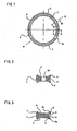
- a main body “a” of the dual-membered suctional gasket comprises an inner sealing member 1, an outer sealing member 2, connecting members 3 for connecting the two sealing members 1, 2 and recessed portions 4 formed on at least one of the upper side and the lower side of the gasket.
- the main body “a” of the suctional gasket is made of any elastic material as far as the material can prevent fluid from leaking when compressed, such as rubber, plastic or the like.
- the gasket can be formed in either a circular shape or in a non-circular shape.
- a reference numeral "5" is lip portions of the outer sealing member 2.
- the upper and lower lip portions 5 of the outer sealing member 2 form a ⁇ shaped cross section and form an annular recessed portion 6 on an outer circumference of the outer sealing member 2 (see FIGs.2 and 3 ).
- a convex portion 7 is formed on an outer circumference of the inner sealing member 1, but lip portions same as those of the outer sealing member 2 can be formed on the inner sealing member 1 instead of the convex portion.
- the gasket can arrange reversely such that the outer sealing member 2 has the convex portion and the inner sealing member has lip portions.
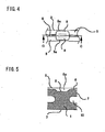
- a reference numeral “8" is air vent valve portions.
- the air vent valve portions 8 are formed at portions on the outer circumference of the outer sealing member 2 connecting to connecting members 3, such that small recessed portions 9 are formed at the recessed portion 6.
- Lip portions 5a at the small recessed portions 9 are formed thinner than the other lip portions 5.
- elastic deformation performance around the lip portions 5a are weakened so that portions around the lip portion 5a are constituted to vent air remaining in the recessed portions 4 of the main body "a" of the gasket, when the sealing members 1, 2 are elastically deformed as illustrated in FIG.8 .
- a width of the connecting member 3 is set larger than a width of the object to which the gasket is fitted, a function to prevent the gasket from falling off can be added by utilizing elasticity of the gasket. Further the connecting members 3 also can prevent the inner and outer sealing members 1, 2 from falling down irregularly. Since the function to prevent the gasket from falling off can be added to respective connecting members 3 apart from each other positioned between the inner and outer sealing members 1, 2, uniform stress is acted on respective sealing members 1, 2 so the uneven deformations on the gasket are minimized.
- a reference numeral "10" is fitting holes formed between the neighboring connecting members 3 (see FIGs.2 and 5 ).
- the fitting holes 10 are fitted to protruded central walls 11, namely, fitting members formed on the object to which the gasket to be fitted (see FIGs7 , 8, 9A-9B ).
- the central walls 11 function as guides to determine positioning and compressed degree of the gasket when fitted and function as a self sealing effect when higher pressure is acted on the gasket.
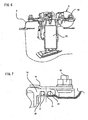
- a reference numeral “12” is a fuel pump arranged on a fuel tank T to which the dual-membered suctional gasket by the present invention is fitted (see FIGs.6 and 7 ).
- a reference numeral “13” is a fuel pump flange of which central walls 11 are fitted in the fitting holes 10 of the dual-membered suctional gasket for fitting to the fuel pump.
- a reference numeral “14” is a pressing plate for fixing the fuel pump flange 13 by screwing a flanged nut 15.
- a reference numeral “16” is an unpainted surface area of the fuel tank T.
- a reference numeral “17” is a painted surface area of the fuel tank T.
- the main body "a" of the suctional gasket is fitted to the central walls 11 of the object via fitting holes 10, so that the whole body of the gasket is fitted in the object (see FIGs.9A and 9C ).
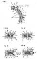
- Air sealed in the recessed portions 4 of the main body "a" of the suctional gasket is compressed by deformations of the inner and outer sealing members 1, 2 when the fuel pump flange 13 is pressed during the fitting step, and then the compressed air is vented outside via air vent valve portions 8 formed outsides of the connecting members 3 as shown in FIG.8 and FIG.9D . Since the lip portions 5 of the outer sealing member 2 have no air vent valve portions 8 as shown in FIG.9B , lip portions 5 are kept being sealed and are slightly bent such that the recessed portions 6 form a deeper ⁇ shaped cross section.
- the lip portions 5a have the same > shape cross section as the lip portions 5, but the lip portions 5a are thinner than the lip portions 5.
- the lip portions 5a form the deeper recessed portions 9 and the air vent valve portions 8 so that lip portions 5a can vent gas outside, but cannot intake gas inside.
- the air vent valve portions 8 have a sort of check valve structure so that gas does not flow into the recessed portions 4, even if the recessed portions 4 are under lowered pressure.
- the gasket by the present invention can enhance the sealing effect.
- a sealing surface area of the tank for preventing fuel from leaking is not painted in order to avoid poor sealing performance caused by thickness fluctuations of coated paint on the sealing surface area.
- unpainted surface areas of the tank might be rusted by penetrated water from outside, which might lead to poor sealing performance
- galvanized steel plate is used for the fuel tank or a waterproof structured fuel tank is employed.
- the gasket by the present invention is formed as the dual-membered gasket comprising the inner and outer sealing members, the inner sealing member 1 seals the unpainted surface area 16 so that it plays a main sealing member for preventing fuel from leaking, and the outer sealing member 2 plays a role of waterproof seal for sealing the painted surface area 17 so that it prevent the unpainted surface from rusting.
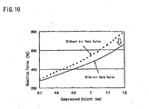
- FIG.10 is the chart showing the relation between compressed extent of gaskets and reaction force of the gaskets.
- FIG.10 indicates that generated reaction force by a gasket with air vent valves can be controlled lower than that of a gasket without air vent valves, since in the gasket with air vent valves, air pressure in the recessed portions between the inner sealing member and outer sealing member is not raised.
- an object to which the gasket by the present invention is fitted should have a sufficient space for accommodating and a height for deforming the dual-membered gasket.
- the inner sealing member 1 has a structure which is rather hard to deform when compressed and the structure is different from that of the outer sealing member 2. Taking a sealing effect against fuel into consideration, the inner sealing member 1 has the structure which can generate higher reaction force when compressed. On the other hand, since strong reaction force from the outer sealing member 2 is not required, it has the lip sealing structure for preventing water penetration from outside.
- connecting members 3 are formed between the inner and outer sealing members 1, 2.
- Small recessed portions 9 are formed on the outer circumferences of the outer sealing members 2 at portions connecting to the connecting members 3. In other words, since areas around the recessed portions 9 generate smaller reaction forces when compressed compared with other portions of the outer sealing members 2, the areas, namely, the air vent valve portions 8 function as a check valve and vent air sealed in the recessed portions 4 between the inner and outer sealing members 1, 2.
- a compressed extent of the gasket should be set preferably 5% to 30% of a height of the gasket.
- a width of the connecting members 3 in a circular direction should be set 1% to 10%, preferably 3% to 7% larger than that of portions of the object to which the gasket is fitted, so that gasket is elastically fitted to the object, which prevent gasket from falling off from the object.
- the main body "a" of the suctional gasket is formed by molding an elastic material.
- Materials for the gasket should be selected depending on the kind of fluid to be scaled. For example, NBR, hydrogenated NBR, fluorocarbon rubber or the like is preferably used for fuel oil. EPDM, fluorocarbon rubber or the like is preferably used for aqueous fluid. If vulcanized rubber is required for the gasket, ingredients are weighed and kneaded before vulcanized, thus an unvulcanized rubber material is obtained.
- a molding die for molding rubber gaskets is prepared. Shapes (hereinafter referred as "cavities") of the gasket by the present invention are formed beforehand in the molding die.
- the unvulcanized rubber material is placed in the preheated cavities of the opened molding die, and is vulcanized by keeping the molding die under a predetermined pressure, at a predetermined temperature for a predetermined period after the molding die is closed (a compression molding).
- the unvulcanized rubber material can be molded by other methods such as a transfer molding where the unvulcanized rubber material in a heated chamber is transferred into the cavities of the closed molding die; an injection molding where the unvulcanized rubber in a heated separate injecting mechanism is injected into the cavities of the molding die and the like.
- the pressure, the temperature and the period for the vulcanizations are generally set 1 to 30MPa, 100°C to 200°C and 2 to 30 minutes respectively.
- the molding die is opened and the molded dual-membered suctional gasket is taken out of the molding die and the gasket is cooled to room temperature.
Landscapes
- Engineering & Computer Science (AREA)
- General Engineering & Computer Science (AREA)
- Mechanical Engineering (AREA)
- Gasket Seals (AREA)
- Sealing Material Composition (AREA)
- Control Of Motors That Do Not Use Commutators (AREA)
- Transition And Organic Metals Composition Catalysts For Addition Polymerization (AREA)
- Cephalosporin Compounds (AREA)
Applications Claiming Priority (2)
| Application Number | Priority Date | Filing Date | Title |
|---|---|---|---|
| JP2004281378A JP4589686B2 (ja) | 2004-09-28 | 2004-09-28 | 二重吸着ガスケット |
| PCT/JP2005/013710 WO2006035544A1 (ja) | 2004-09-28 | 2005-07-27 | 二重吸着ガスケット |
Publications (3)
| Publication Number | Publication Date |
|---|---|
| EP1801470A1 EP1801470A1 (en) | 2007-06-27 |
| EP1801470A4 EP1801470A4 (en) | 2008-04-30 |
| EP1801470B1 true EP1801470B1 (en) | 2009-10-14 |
Family
ID=36118698
Family Applications (1)
| Application Number | Title | Priority Date | Filing Date |
|---|---|---|---|
| EP05767023A Not-in-force EP1801470B1 (en) | 2004-09-28 | 2005-07-27 | Double suction gasket |
Country Status (9)
| Country | Link |
|---|---|
| US (1) | US7624993B2 (ko) |
| EP (1) | EP1801470B1 (ko) |
| JP (1) | JP4589686B2 (ko) |
| KR (1) | KR20070083603A (ko) |
| CN (1) | CN101036009B (ko) |
| AT (1) | ATE445796T1 (ko) |
| BR (1) | BRPI0515834B1 (ko) |
| DE (1) | DE602005017168D1 (ko) |
| WO (1) | WO2006035544A1 (ko) |
Families Citing this family (23)
| Publication number | Priority date | Publication date | Assignee | Title |
|---|---|---|---|---|
| US7938406B2 (en) * | 2005-07-07 | 2011-05-10 | Nok Corporation | Gasket |
| WO2009152816A1 (de) * | 2008-06-21 | 2009-12-23 | Federal-Mogul Sealing Systems Gmbh | Dichtungselement zur abdichtung von flanschflächen bei brennkraftmaschinen |
| US8419021B2 (en) * | 2008-10-31 | 2013-04-16 | Ti Group Automotive Systems, L.L.C. | Ring seal with insert |
| DE102009005697B4 (de) * | 2009-01-22 | 2013-05-23 | Ivoclar Vivadent Ag | Ausbringvorrichtung und deren Verwendung |
| JP2011190698A (ja) * | 2010-03-12 | 2011-09-29 | Denso Corp | スロットル弁装置 |
| US8444152B2 (en) * | 2011-05-04 | 2013-05-21 | General Electric Company | Spring seal assembly and method of sealing a gap |
| BR112014005200B1 (pt) * | 2011-09-07 | 2021-05-11 | Honda Motor Co., Ltd | estrutura de vedação para bomba de combustível |
| KR101153729B1 (ko) * | 2011-09-29 | 2012-06-14 | 이프로링크텍(주) | 금속가스켓 |
| KR101354119B1 (ko) * | 2012-05-02 | 2014-01-27 | 동아공업 주식회사 | 피어싱이 형성된 스토퍼를 갖는 가스켓 |
| CN104154233B (zh) * | 2013-05-15 | 2016-08-31 | 北京北方微电子基地设备工艺研究中心有限责任公司 | 密封转接件及半导体工艺设备 |
| US9739378B2 (en) | 2014-04-17 | 2017-08-22 | Vistadeltek, Llc | Ultra-seal gasket for joining high purity fluid pathways |
| EP3137793B1 (en) * | 2014-04-29 | 2019-11-27 | Cummins, Inc. | Pressure controlled dynamic seal with captured fluid transfer tubes |
| CN104154102A (zh) * | 2014-07-22 | 2014-11-19 | 宁国天运橡塑制品有限公司 | 一种不易脱落的垫圈 |
| JP6300276B2 (ja) * | 2014-12-15 | 2018-03-28 | 本田技研工業株式会社 | 燃料ポンプユニットのシール構造 |
| CN105402402B (zh) * | 2015-10-30 | 2017-09-12 | 宁波凌珂新材料科技有限公司 | 气压式密封垫片 |
| CN105240529A (zh) * | 2015-11-06 | 2016-01-13 | 天津大学 | 一种密封圈密封装置 |
| EP3236114A1 (de) * | 2016-04-19 | 2017-10-25 | Siemens Aktiengesellschaft | Dichtung für geräte der nahrungs- und genussmittelindustrie |
| CN107339431A (zh) * | 2017-07-26 | 2017-11-10 | 盐城润浩密封件科技有限公司 | 一种径向密封件 |
| CN110822083B (zh) * | 2018-08-09 | 2022-03-08 | 翰昂汽车零部件有限公司 | 用以防止爆发性减压的损害的密封构型 |
| US11371639B2 (en) | 2018-08-09 | 2022-06-28 | Hanon Systems | Seal configuration to prevent damage from explosive decompression |
| JP6547237B1 (ja) * | 2019-02-26 | 2019-07-24 | 千住金属工業株式会社 | はんだ付け装置及びはんだ付け装置にパッキンを固定する方法 |
| DE102020208496A1 (de) * | 2020-07-07 | 2022-01-13 | Carl Zeiss Smt Gmbh | Wasserführendes system und lithographieanlage |
| JP7353577B2 (ja) | 2021-08-27 | 2023-10-02 | 日本発條株式会社 | カバー及び記録装置 |
Family Cites Families (52)
| Publication number | Priority date | Publication date | Assignee | Title |
|---|---|---|---|---|
| DE256905C (ko) | 1911-10-12 | 1913-02-24 | ||
| US2910209A (en) * | 1953-08-18 | 1959-10-27 | Walter K Nelson | Sealer strips |
| US2908480A (en) * | 1955-01-31 | 1959-10-13 | Chiksan Co | Pressure relieved valve seal |
| US2820569A (en) * | 1955-05-31 | 1958-01-21 | Gen Motors Corp | Cap for tank filler pipe |
| US2754136A (en) * | 1955-07-12 | 1956-07-10 | Gray Tool Co | Pressure actuated seal between concentric pipes |
| US2853330A (en) * | 1956-08-13 | 1958-09-23 | Henry A Harry | Multi-ribbed sealing strip |
| US2882081A (en) * | 1956-11-15 | 1959-04-14 | Garlock Packing Co | Seal |
| US2983533A (en) * | 1957-01-22 | 1961-05-09 | A P D Co | Sealing ring |
| US2981232A (en) * | 1957-04-10 | 1961-04-25 | Renault | Differential pressure pneumatic jacks adapted for automatic return to initial position |
| US3031200A (en) * | 1959-06-22 | 1962-04-24 | Chiksan Co | Fluid seal |
| US3290047A (en) * | 1963-02-11 | 1966-12-06 | North American Aviation Inc | Relief seal with dual sealing surfaces |
| JPS453221Y1 (ko) | 1965-07-31 | 1970-02-13 | ||
| US3831950A (en) * | 1971-11-10 | 1974-08-27 | Chicago Bridge & Iron Co | Gasket for closure seal |
| JPS645902Y2 (ko) * | 1980-02-05 | 1989-02-14 | ||
| JPS56114589A (en) | 1980-02-14 | 1981-09-09 | Agency Of Ind Science & Technol | Manufacture of metallic product with hole |
| US4337956A (en) * | 1980-12-30 | 1982-07-06 | American Sterilizer Company | Double lip seal with pressure compensation |
| US4434909A (en) * | 1981-02-12 | 1984-03-06 | National Presto Industries, Inc. | Pressure cooker interlock |
| US4441724A (en) * | 1981-03-16 | 1984-04-10 | American Sterilizer Company | Fluid-tight seal |
| US4372565A (en) * | 1981-03-17 | 1983-02-08 | Baker Manufacturing Company | Soft metal seal |
| US4469335A (en) | 1982-07-22 | 1984-09-04 | American Sterilizer Company | Sealing apparatus with sealing device operable under pressure differential established thereacross |
| GB2127910B (en) | 1982-09-27 | 1986-01-29 | American Sterilizer Co | Fluid tight seal |
| GB2139318B (en) * | 1983-05-04 | 1986-07-23 | Dowty Seals Ltd | Piston/cylinder seal construction |
| US4511152A (en) * | 1984-02-08 | 1985-04-16 | Aeroquip Corporation | Self-reinforced face seal |
| DD256905A1 (de) * | 1986-12-31 | 1988-05-25 | Karl Marx Stadt Tech Hochschul | Hochdruckdichtungsanordnung |
| US4884723A (en) * | 1987-04-23 | 1989-12-05 | Acf Industries, Incorporated | Hard gasket for retrofit installation on hopper outlet/hopper gasket outlet |
| JPH01261566A (ja) * | 1988-04-08 | 1989-10-18 | Smc Corp | 流体圧機器のシール装置 |
| JP2881781B2 (ja) | 1988-11-08 | 1999-04-12 | ローム 株式会社 | Ic化されたダイヤラ回路 |
| FR2644217A1 (fr) | 1989-03-07 | 1990-09-14 | Procal | Joint d'etancheite statique |
| US5169160A (en) * | 1991-11-27 | 1992-12-08 | Parker Hannifin Corporation | Lubricating seal for pneumatic cylinder |
| US5328178A (en) * | 1992-10-14 | 1994-07-12 | General Motors Corporation | Brake master cylinder seal |
| US5429374A (en) * | 1992-12-04 | 1995-07-04 | Ford Motor Company | Pressure sensitive resilient dynamic seal |
| US5280769A (en) * | 1993-05-04 | 1994-01-25 | General Motors Corporation | Pressure relief means for induction system |
| FR2720465B1 (fr) * | 1994-05-27 | 1996-07-26 | Seb Sa | Dispositif de sécurité pour récipient sous pression comportant un joint d'étanchéité à section affaiblie. |
| JPH0813594A (ja) | 1994-06-29 | 1996-01-16 | Inax Corp | 衛生器具の排水管への接続構造 |
| US5493954A (en) * | 1994-11-18 | 1996-02-27 | Flow International Corporation | Self-venting seal assembly |
| CN2217146Y (zh) * | 1995-04-20 | 1996-01-10 | 河南省冷柜厂 | 密封圈 |
| JPH0914448A (ja) * | 1995-06-23 | 1997-01-14 | Nok Corp | ガスケット |
| EP0781712B1 (en) * | 1995-08-10 | 2001-12-05 | Osaka Shipbuilding Co., Ltd. | Lid mounting structure for pressure vessel |
| JPH0982402A (ja) * | 1995-09-07 | 1997-03-28 | Yazaki Corp | シールパッキン及び機器直付けコネクタ |
| JPH10259875A (ja) | 1997-03-21 | 1998-09-29 | Hitachi Zosen Corp | 二重シールガスケット |
| JPH11108192A (ja) | 1997-10-02 | 1999-04-20 | Isuzu Motors Ltd | 弾性シール部材 |
| JP2000240800A (ja) * | 1999-02-18 | 2000-09-05 | Masuda Mitsuru | パッキング |
| JP3349132B2 (ja) * | 1999-04-12 | 2002-11-20 | 三菱電線工業株式会社 | 低荷重シール |
| US6340162B1 (en) * | 1999-08-13 | 2002-01-22 | Trw Inc. | Seal for integral power steering gear |
| US6357760B1 (en) * | 2000-05-19 | 2002-03-19 | Michael Doyle | Ring seal |
| JP2002282118A (ja) * | 2001-03-28 | 2002-10-02 | Aron Kasei Co Ltd | 吸 盤 |
| AU2002324725A1 (en) | 2001-08-16 | 2003-03-03 | Parker Hannifin Corporation | Composite fuel permeation barrier seal |
| JP4292321B2 (ja) | 2001-12-07 | 2009-07-08 | 内山工業株式会社 | ガスケット |
| JP2003207051A (ja) * | 2002-01-11 | 2003-07-25 | Nok Corp | 密封装置 |
| JP2003294145A (ja) | 2002-04-02 | 2003-10-15 | Sony Corp | シール具、シールリング用保持具、シール方法 |
| KR20030097433A (ko) * | 2002-06-21 | 2003-12-31 | 박종도 | 압력 조절용 패킹 |
| JP4556205B2 (ja) * | 2003-03-28 | 2010-10-06 | ニチアス株式会社 | 金属ガスケット |
-
2004
- 2004-09-28 JP JP2004281378A patent/JP4589686B2/ja active Active
-
2005
- 2005-07-27 WO PCT/JP2005/013710 patent/WO2006035544A1/ja active Application Filing
- 2005-07-27 AT AT05767023T patent/ATE445796T1/de not_active IP Right Cessation
- 2005-07-27 US US11/664,041 patent/US7624993B2/en not_active Expired - Fee Related
- 2005-07-27 KR KR1020077007001A patent/KR20070083603A/ko active Search and Examination
- 2005-07-27 DE DE602005017168T patent/DE602005017168D1/de not_active Expired - Fee Related
- 2005-07-27 BR BRPI0515834-6A patent/BRPI0515834B1/pt active IP Right Grant
- 2005-07-27 EP EP05767023A patent/EP1801470B1/en not_active Not-in-force
- 2005-07-27 CN CN2005800328072A patent/CN101036009B/zh active Active
Also Published As
| Publication number | Publication date |
|---|---|
| EP1801470A1 (en) | 2007-06-27 |
| JP2006097721A (ja) | 2006-04-13 |
| CN101036009A (zh) | 2007-09-12 |
| ATE445796T1 (de) | 2009-10-15 |
| EP1801470A4 (en) | 2008-04-30 |
| BRPI0515834B1 (pt) | 2019-11-12 |
| US7624993B2 (en) | 2009-12-01 |
| US20080067760A1 (en) | 2008-03-20 |
| JP4589686B2 (ja) | 2010-12-01 |
| WO2006035544A1 (ja) | 2006-04-06 |
| BRPI0515834A (pt) | 2008-08-12 |
| CN101036009B (zh) | 2010-07-21 |
| KR20070083603A (ko) | 2007-08-24 |
| DE602005017168D1 (de) | 2009-11-26 |
Similar Documents
| Publication | Publication Date | Title |
|---|---|---|
| EP1801470B1 (en) | Double suction gasket | |
| CN101091078A (zh) | 垫片 | |
| CN100378379C (zh) | 带有压力释放通道和膨胀空隙的阀密封件 | |
| EP1350994A3 (en) | Metallic gasket | |
| CN111936773B (zh) | 密封件和流体阀 | |
| US20180119835A1 (en) | Unit for the Regulation or Control of a Fluid Pressure | |
| CN207018533U (zh) | 密封圈 | |
| US20080226862A1 (en) | Barrier Gasket | |
| US20090261534A1 (en) | Sealing gasket and uses of such a gasket | |
| US5275420A (en) | End seals for V-type internal combustion engines and engine sealing method | |
| WO2005089389A2 (en) | Pump sealing apparatus | |
| JPH01245934A (ja) | 金属ガスケットの製造方法 | |
| JP4538238B2 (ja) | ガスケット | |
| US20060005372A1 (en) | Method for producing a gasket | |
| US20170097092A1 (en) | Variable Compression Height Integrated Seal | |
| JPH051727Y2 (ko) | ||
| JP3040299B2 (ja) | 波紋形ダイヤフラム式アキュムレータ | |
| CN220185891U (zh) | 一种通过气动执行器控制的高压球阀 | |
| CN210716004U (zh) | 一种蝶阀密封结构 | |
| CN215410143U (zh) | 真空比例阀密封复合件 | |
| CN214466287U (zh) | 内连接式气动隔膜阀 | |
| JPH0325460Y2 (ko) | ||
| CN214617962U (zh) | 外连接式气动隔膜阀 | |
| CN218455004U (zh) | 一种气动减压阀橡胶膜片 | |
| CN2132040Y (zh) | 无泄漏耐压截止阀 |
Legal Events
| Date | Code | Title | Description |
|---|---|---|---|
| PUAI | Public reference made under article 153(3) epc to a published international application that has entered the european phase |
Free format text: ORIGINAL CODE: 0009012 |
|
| 17P | Request for examination filed |
Effective date: 20070416 |
|
| AK | Designated contracting states |
Kind code of ref document: A1 Designated state(s): AT BE BG CH CY CZ DE DK EE ES FI FR GB GR HU IE IS IT LI LT LU LV MC NL PL PT RO SE SI SK TR |
|
| DAX | Request for extension of the european patent (deleted) | ||
| A4 | Supplementary search report drawn up and despatched |
Effective date: 20080331 |
|
| RIC1 | Information provided on ipc code assigned before grant |
Ipc: F16J 15/10 20060101AFI20060817BHEP Ipc: F16J 15/02 20060101ALI20080325BHEP |
|
| GRAP | Despatch of communication of intention to grant a patent |
Free format text: ORIGINAL CODE: EPIDOSNIGR1 |
|
| GRAS | Grant fee paid |
Free format text: ORIGINAL CODE: EPIDOSNIGR3 |
|
| GRAA | (expected) grant |
Free format text: ORIGINAL CODE: 0009210 |
|
| AK | Designated contracting states |
Kind code of ref document: B1 Designated state(s): AT BE BG CH CY CZ DE DK EE ES FI FR GB GR HU IE IS IT LI LT LU LV MC NL PL PT RO SE SI SK TR |
|
| REG | Reference to a national code |
Ref country code: GB Ref legal event code: FG4D |
|
| REG | Reference to a national code |
Ref country code: CH Ref legal event code: EP |
|
| REG | Reference to a national code |
Ref country code: IE Ref legal event code: FG4D |
|
| REF | Corresponds to: |
Ref document number: 602005017168 Country of ref document: DE Date of ref document: 20091126 Kind code of ref document: P |
|
| REG | Reference to a national code |
Ref country code: GR Ref legal event code: EP Ref document number: 20090403056 Country of ref document: GR |
|
| LTIE | Lt: invalidation of european patent or patent extension |
Effective date: 20091014 |
|
| NLV1 | Nl: lapsed or annulled due to failure to fulfill the requirements of art. 29p and 29m of the patents act | ||
| PG25 | Lapsed in a contracting state [announced via postgrant information from national office to epo] |
Ref country code: IS Free format text: LAPSE BECAUSE OF FAILURE TO SUBMIT A TRANSLATION OF THE DESCRIPTION OR TO PAY THE FEE WITHIN THE PRESCRIBED TIME-LIMIT Effective date: 20100214 Ref country code: LT Free format text: LAPSE BECAUSE OF FAILURE TO SUBMIT A TRANSLATION OF THE DESCRIPTION OR TO PAY THE FEE WITHIN THE PRESCRIBED TIME-LIMIT Effective date: 20091014 Ref country code: FI Free format text: LAPSE BECAUSE OF FAILURE TO SUBMIT A TRANSLATION OF THE DESCRIPTION OR TO PAY THE FEE WITHIN THE PRESCRIBED TIME-LIMIT Effective date: 20091014 Ref country code: PT Free format text: LAPSE BECAUSE OF FAILURE TO SUBMIT A TRANSLATION OF THE DESCRIPTION OR TO PAY THE FEE WITHIN THE PRESCRIBED TIME-LIMIT Effective date: 20100215 Ref country code: SE Free format text: LAPSE BECAUSE OF FAILURE TO SUBMIT A TRANSLATION OF THE DESCRIPTION OR TO PAY THE FEE WITHIN THE PRESCRIBED TIME-LIMIT Effective date: 20091014 Ref country code: ES Free format text: LAPSE BECAUSE OF FAILURE TO SUBMIT A TRANSLATION OF THE DESCRIPTION OR TO PAY THE FEE WITHIN THE PRESCRIBED TIME-LIMIT Effective date: 20100125 |
|
| PG25 | Lapsed in a contracting state [announced via postgrant information from national office to epo] |
Ref country code: PL Free format text: LAPSE BECAUSE OF FAILURE TO SUBMIT A TRANSLATION OF THE DESCRIPTION OR TO PAY THE FEE WITHIN THE PRESCRIBED TIME-LIMIT Effective date: 20091014 Ref country code: SI Free format text: LAPSE BECAUSE OF FAILURE TO SUBMIT A TRANSLATION OF THE DESCRIPTION OR TO PAY THE FEE WITHIN THE PRESCRIBED TIME-LIMIT Effective date: 20091014 Ref country code: LV Free format text: LAPSE BECAUSE OF FAILURE TO SUBMIT A TRANSLATION OF THE DESCRIPTION OR TO PAY THE FEE WITHIN THE PRESCRIBED TIME-LIMIT Effective date: 20091014 |
|
| PG25 | Lapsed in a contracting state [announced via postgrant information from national office to epo] |
Ref country code: AT Free format text: LAPSE BECAUSE OF FAILURE TO SUBMIT A TRANSLATION OF THE DESCRIPTION OR TO PAY THE FEE WITHIN THE PRESCRIBED TIME-LIMIT Effective date: 20091014 Ref country code: BE Free format text: LAPSE BECAUSE OF FAILURE TO SUBMIT A TRANSLATION OF THE DESCRIPTION OR TO PAY THE FEE WITHIN THE PRESCRIBED TIME-LIMIT Effective date: 20091014 |
|
| PG25 | Lapsed in a contracting state [announced via postgrant information from national office to epo] |
Ref country code: EE Free format text: LAPSE BECAUSE OF FAILURE TO SUBMIT A TRANSLATION OF THE DESCRIPTION OR TO PAY THE FEE WITHIN THE PRESCRIBED TIME-LIMIT Effective date: 20091014 Ref country code: BG Free format text: LAPSE BECAUSE OF FAILURE TO SUBMIT A TRANSLATION OF THE DESCRIPTION OR TO PAY THE FEE WITHIN THE PRESCRIBED TIME-LIMIT Effective date: 20100114 Ref country code: DK Free format text: LAPSE BECAUSE OF FAILURE TO SUBMIT A TRANSLATION OF THE DESCRIPTION OR TO PAY THE FEE WITHIN THE PRESCRIBED TIME-LIMIT Effective date: 20091014 Ref country code: RO Free format text: LAPSE BECAUSE OF FAILURE TO SUBMIT A TRANSLATION OF THE DESCRIPTION OR TO PAY THE FEE WITHIN THE PRESCRIBED TIME-LIMIT Effective date: 20091014 |
|
| PLBE | No opposition filed within time limit |
Free format text: ORIGINAL CODE: 0009261 |
|
| STAA | Information on the status of an ep patent application or granted ep patent |
Free format text: STATUS: NO OPPOSITION FILED WITHIN TIME LIMIT |
|
| PG25 | Lapsed in a contracting state [announced via postgrant information from national office to epo] |
Ref country code: CZ Free format text: LAPSE BECAUSE OF FAILURE TO SUBMIT A TRANSLATION OF THE DESCRIPTION OR TO PAY THE FEE WITHIN THE PRESCRIBED TIME-LIMIT Effective date: 20091014 Ref country code: SK Free format text: LAPSE BECAUSE OF FAILURE TO SUBMIT A TRANSLATION OF THE DESCRIPTION OR TO PAY THE FEE WITHIN THE PRESCRIBED TIME-LIMIT Effective date: 20091014 |
|
| 26N | No opposition filed |
Effective date: 20100715 |
|
| PG25 | Lapsed in a contracting state [announced via postgrant information from national office to epo] |
Ref country code: MC Free format text: LAPSE BECAUSE OF NON-PAYMENT OF DUE FEES Effective date: 20100731 |
|
| REG | Reference to a national code |
Ref country code: CH Ref legal event code: PL |
|
| PG25 | Lapsed in a contracting state [announced via postgrant information from national office to epo] |
Ref country code: LI Free format text: LAPSE BECAUSE OF NON-PAYMENT OF DUE FEES Effective date: 20100731 Ref country code: DE Free format text: LAPSE BECAUSE OF NON-PAYMENT OF DUE FEES Effective date: 20110201 Ref country code: CH Free format text: LAPSE BECAUSE OF NON-PAYMENT OF DUE FEES Effective date: 20100731 |
|
| REG | Reference to a national code |
Ref country code: DE Ref legal event code: R119 Ref document number: 602005017168 Country of ref document: DE Effective date: 20110201 |
|
| PG25 | Lapsed in a contracting state [announced via postgrant information from national office to epo] |
Ref country code: IE Free format text: LAPSE BECAUSE OF NON-PAYMENT OF DUE FEES Effective date: 20100727 |
|
| PG25 | Lapsed in a contracting state [announced via postgrant information from national office to epo] |
Ref country code: CY Free format text: LAPSE BECAUSE OF FAILURE TO SUBMIT A TRANSLATION OF THE DESCRIPTION OR TO PAY THE FEE WITHIN THE PRESCRIBED TIME-LIMIT Effective date: 20091014 |
|
| PG25 | Lapsed in a contracting state [announced via postgrant information from national office to epo] |
Ref country code: HU Free format text: LAPSE BECAUSE OF FAILURE TO SUBMIT A TRANSLATION OF THE DESCRIPTION OR TO PAY THE FEE WITHIN THE PRESCRIBED TIME-LIMIT Effective date: 20100415 Ref country code: NL Free format text: LAPSE BECAUSE OF FAILURE TO SUBMIT A TRANSLATION OF THE DESCRIPTION OR TO PAY THE FEE WITHIN THE PRESCRIBED TIME-LIMIT Effective date: 20091014 Ref country code: LU Free format text: LAPSE BECAUSE OF NON-PAYMENT OF DUE FEES Effective date: 20100727 |
|
| PG25 | Lapsed in a contracting state [announced via postgrant information from national office to epo] |
Ref country code: TR Free format text: LAPSE BECAUSE OF FAILURE TO SUBMIT A TRANSLATION OF THE DESCRIPTION OR TO PAY THE FEE WITHIN THE PRESCRIBED TIME-LIMIT Effective date: 20091014 |
|
| PGFP | Annual fee paid to national office [announced via postgrant information from national office to epo] |
Ref country code: GB Payment date: 20120719 Year of fee payment: 8 |
|
| PGFP | Annual fee paid to national office [announced via postgrant information from national office to epo] |
Ref country code: IT Payment date: 20120725 Year of fee payment: 8 |
|
| PGFP | Annual fee paid to national office [announced via postgrant information from national office to epo] |
Ref country code: GR Payment date: 20130729 Year of fee payment: 9 |
|
| PGFP | Annual fee paid to national office [announced via postgrant information from national office to epo] |
Ref country code: FR Payment date: 20130722 Year of fee payment: 9 |
|
| GBPC | Gb: european patent ceased through non-payment of renewal fee |
Effective date: 20130727 |
|
| PG25 | Lapsed in a contracting state [announced via postgrant information from national office to epo] |
Ref country code: GB Free format text: LAPSE BECAUSE OF NON-PAYMENT OF DUE FEES Effective date: 20130727 |
|
| PG25 | Lapsed in a contracting state [announced via postgrant information from national office to epo] |
Ref country code: IT Free format text: LAPSE BECAUSE OF NON-PAYMENT OF DUE FEES Effective date: 20130727 |
|
| REG | Reference to a national code |
Ref country code: GR Ref legal event code: ML Ref document number: 20090403056 Country of ref document: GR Effective date: 20150204 |
|
| REG | Reference to a national code |
Ref country code: FR Ref legal event code: ST Effective date: 20150331 |
|
| PG25 | Lapsed in a contracting state [announced via postgrant information from national office to epo] |
Ref country code: GR Free format text: LAPSE BECAUSE OF NON-PAYMENT OF DUE FEES Effective date: 20150204 Ref country code: FR Free format text: LAPSE BECAUSE OF NON-PAYMENT OF DUE FEES Effective date: 20140731 |