EP1777662A1 - Dispositif de manipulation de jeton - Google Patents
Dispositif de manipulation de jeton Download PDFInfo
- Publication number
- EP1777662A1 EP1777662A1 EP06122698A EP06122698A EP1777662A1 EP 1777662 A1 EP1777662 A1 EP 1777662A1 EP 06122698 A EP06122698 A EP 06122698A EP 06122698 A EP06122698 A EP 06122698A EP 1777662 A1 EP1777662 A1 EP 1777662A1
- Authority
- EP
- European Patent Office
- Prior art keywords
- token
- sensor
- rolling
- thickness
- cancel
- Prior art date
- Legal status (The legal status is an assumption and is not a legal conclusion. Google has not performed a legal analysis and makes no representation as to the accuracy of the status listed.)
- Granted
Links
Images


Classifications
-
- A—HUMAN NECESSITIES
- A63—SPORTS; GAMES; AMUSEMENTS
- A63F—CARD, BOARD, OR ROULETTE GAMES; INDOOR GAMES USING SMALL MOVING PLAYING BODIES; VIDEO GAMES; GAMES NOT OTHERWISE PROVIDED FOR
- A63F7/00—Indoor games using small moving playing bodies, e.g. balls, discs or blocks
- A63F7/22—Accessories; Details
- A63F7/24—Devices controlled by the player to project or roll-off the playing bodies
- A63F7/28—Devices controlled by the player to project or roll-off the playing bodies using gravity, i.e. apparatus for rolling off the ball, e.g. a slope, ramp or slant
-
- G—PHYSICS
- G07—CHECKING-DEVICES
- G07F—COIN-FREED OR LIKE APPARATUS
- G07F1/00—Coin inlet arrangements; Coins specially adapted to operate coin-freed mechanisms
- G07F1/02—Coin slots
-
- A—HUMAN NECESSITIES
- A63—SPORTS; GAMES; AMUSEMENTS
- A63F—CARD, BOARD, OR ROULETTE GAMES; INDOOR GAMES USING SMALL MOVING PLAYING BODIES; VIDEO GAMES; GAMES NOT OTHERWISE PROVIDED FOR
- A63F7/00—Indoor games using small moving playing bodies, e.g. balls, discs or blocks
- A63F7/02—Indoor games using small moving playing bodies, e.g. balls, discs or blocks using falling playing bodies or playing bodies running on an inclined surface, e.g. pinball games
-
- A—HUMAN NECESSITIES
- A63—SPORTS; GAMES; AMUSEMENTS
- A63F—CARD, BOARD, OR ROULETTE GAMES; INDOOR GAMES USING SMALL MOVING PLAYING BODIES; VIDEO GAMES; GAMES NOT OTHERWISE PROVIDED FOR
- A63F7/00—Indoor games using small moving playing bodies, e.g. balls, discs or blocks
- A63F7/22—Accessories; Details
- A63F7/24—Devices controlled by the player to project or roll-off the playing bodies
- A63F7/2409—Apparatus for projecting the balls
-
- G—PHYSICS
- G07—CHECKING-DEVICES
- G07D—HANDLING OF COINS OR VALUABLE PAPERS, e.g. TESTING, SORTING BY DENOMINATIONS, COUNTING, DISPENSING, CHANGING OR DEPOSITING
- G07D5/00—Testing specially adapted to determine the identity or genuineness of coins, e.g. for segregating coins which are unacceptable or alien to a currency
- G07D5/02—Testing the dimensions, e.g. thickness, diameter; Testing the deformation
-
- G—PHYSICS
- G07—CHECKING-DEVICES
- G07D—HANDLING OF COINS OR VALUABLE PAPERS, e.g. TESTING, SORTING BY DENOMINATIONS, COUNTING, DISPENSING, CHANGING OR DEPOSITING
- G07D5/00—Testing specially adapted to determine the identity or genuineness of coins, e.g. for segregating coins which are unacceptable or alien to a currency
- G07D5/08—Testing the magnetic or electric properties
Definitions
- the present invention relates to a token handling device for handling tokens input into a game machine.
- a conventional token handling device is used as an input device for a game machine.
- a token that is less than a predetermined thickness is permitted to pass through the bottom of a token guide passage along which the token rolls, while a token selecting hole that prevents passage of the token equal to or more than a predetermined thickness is provided.
- a small diameter token removing means is provided that removes the token of less than the predetermined diameter to the lateral side of the guide passage (for example, see Japanese Patent Application Laid-Open No. 11 76598 ( Figures 1 to 3, Pages 2 to 4)).
- the tokens that are inputted but below the standard of the diameter and thickness of the token are sometimes cancelled.
- the mixture of the tokens of another hall is conducive to using the tokens of another hall by the client, and this obliges removing operations of the tokens of another hall from all the tokens after the close of one day business, and causes a problem requiring a great deal of labor and time.
- a "token” is intended to refer to any disc shaped member, typically metal, and including coins and medals.
- a token handling device for a game machine comprises a rolling rail extending from an input port to an output port whereby a token input into the input port rolls along the rolling rail to drop into a predetermined position of a game machine, and a token selecting device positioned along the rolling rail, characterized in that the token selecting device at least includes a token material sensor, and a cancel device downstream of the material sensor that is selectively operable to remove a token from the rolling rail based on a signal from the material sensor.
- the present invention provides a token selecting device capable of cancelling the tokens at least different in material used in the token input device of the game machine.
- the present invention also provides a small-sized token selecting device installable on the token input device of the game machine.
- the present invention can also provide a token selecting device capable of easily changing the setting of the tokens to be selected in the token input device of the game machine.
- the token during the course of rolling on the rolling rail is detected at least by the material sensor, and based on the signal from the material sensor, its authenticity is discriminated.
- the cancel device positioned downstream of the material sensor is operated, and the token is removed from the rolling rail and rejected.
- the selecting device includes a token diameter coil type magnetic sensor disposed at a predetermined distance from the rolling rail that obtains data regarding the diameter of the token, a material coil type magnetic sensor that obtains data regarding the material and thickness of the token disposed adjacent to the token rolling passage closer to the rolling rail than the token diameter coil type magnetic sensor, and a thickness coil type magnetic sensor that obtains data regarding the thickness of the token.
- the selecting device includes a diameter sensor and material sensor and thickness sensor configured by the coil type magnetic sensor.
- the inputted token is discriminated whether it is true or not by material, diameter, and thickness, and therefore, there is the advantage that selecting accuracy of another hall token is high.
- the data regarding the material and thickness of the token is detected by one thickness coil type magnetic sensor.
- the selecting device can be made small-sized.
- the material magnetic sensor and the thickness magnetic sensor are disposed at the position closer to the rolling rail than the diameter sensor, and therefore, can be disposed to be overlapped in the extending direction of the rolling rail, and there is the advantage that the total length thereof can be made short.
- the device is characterized in that the material coil type magnetic sensor and thickness coil type magnetic sensor include central cylinders in the center, and include external walls at the outside of the central cylinders, and ring shaped thickness coils are disposed at the outside of the central cylinders of pot type cores by which bottom wall these central cylinders and the external walls are connected, and ring type material coils are disposed at the outside of the thickness coils.
- the material and thickness sensors are disposed in the common pot core, and therefore, there is the advantage that the selecting device can be made small-sized.
- the device may be characterized in that the cancel device includes a canceller pivotally attached to a pivot axis disposed in parallel with the token rolling passage at the lateral side of the token rolling passage, and the canceller has a free end positioned at the opposite side of the pivot axis reciprocated in the rolling passage.
- the canceller performs a pivot movement for the rolling passage of the token with the pivot axis of the upper stream side as a point of support, and the top end portion thereof protrudes from the cross sectional direction toward the rolling passage.
- the canceller is obliquely positioned relative to the rolling passage, and therefore, the token is gradually deviated from the rolling rail, and therefore, there is the advantage that the tokens continuously rolled can be surely cancelled.
- the cancel device may include a movable guide that guides an upper end side surface of the token rolling at the opposite side of the canceller for the rolling rail.
- the rolling rail when the rolling rail is slightly moved left and right, the top end portion of the token is held by a side surface guide, and therefore it is not dropped from the rolling rail.
- the movable guide may be elastically biased towards the token rolling passage.
- the false token is deviated from the rolling rail, and can drop.
- the movable guide is elastically moved, and the movement is reduced in force, and therefore, the token drops approximately downward.
- a timing sensor of the token may be disposed between the material sensor and the canceller device, and based on false and true signals based on the signal from the material sensor and the detection of the timing sensor, a control device that operates the canceller device is provided.
- a distance between the timing sensor and the canceller is constant, and since the token moves at a constant speed, the token is in opposition to the canceller or before being in an opposition to the canceller, the canceller can be protruded to the rolling passage.
- the device may further comprise a selection reference value obtaining mode setting means; a storing means that stores a token signal from the sensor device at the selection reference value obtaining mode time; a calculating means that calculates the reference value based on the data stored in the storing means; and an means that sets the reference value based on the calculation result of the calculating means.
- the selecting device is set to the selection reference value obtaining mode by the mode setting means, and moreover, when a true token is inputted, the signal at least from the material sensor is stored.
- the data that is obtained from the stored at least material sensor is processed for the preparation of the reference value by calculating means.
- This prepared reference value is set to the reference value by setting means.
- a token input device 100 of a game machine has the functions of allowing a game token 104 inputted to an input port 102 to roll along a rolling rail 106 and drop from a throw-out port 108, and at the same time, cancelling a false or counterfeit token rolling on a rolling rail 106.
- the token input device 100 includes a rolling rail 106, a pivot bearing 110 of the rolling rail 106, a token input port 102, a token selecting device 112, and a throw-out port 108.
- the rolling rail 106 has the functions of allowing the token 104 inputted from the input port 102 to roll along and be guided to the throw-out port 108.
- the rolling rail 106 has a slightly wider thickness than the thickness of the token 104 to be inputted, and moreover, includes a linear guide rail 116 ( Figure 4) which defines a rolling surface 114 with its upper surface elongated, and tabular left guide plate 118 and right guide plate 120 fixed to respective sides of this guide rail 116.
- the rolling rail 106 is fixed to the pivot bearing 110 at a predetermined angle with its front slanting downward.
- Front slanting downward means a state in which the throw-out port 108 is significantly lower than the input port 102.
- the token 104 rolls along a rolling passage 122, which is elongated and narrow in width and surrounded by the rolling surface 114 of the guide rail 116, the left guide plate 118, and the right guide plate 120.
- the pivot bearing 110 holds the rolling rail 106 at a predetermined angle, and at the same time, holds it pivotally around an axis line within a range of small angles.
- the pivot bearing 110 takes on a shaft shape approximately extending vertically, and support axes 130 and 132 protruding upward and downward from the bearing are pivotally supported by a frame body (not shown) of the game machine within a range of small angles.
- a through hole 134 is bored across the axle center of the pivot axis 110.
- the rolling rail 106 is inserted into the through hole 134, and its median is fixed to the pivot axis 110.
- the rolling rail 106 is pivotable within a range of the predetermined small angles left and right around the support axes 130 and 132.
- This pivotal movement of small angles is used for the client to control timing by which the token 104 drops from the input device 100.
- the rolling rail 106 is pivotable left and right little by little, and as a result, the token 104 rolling on the rolling surface 114 is brought into contact with the left guide plate 118 and the right guide plate 120 so as to be given a braking force, and by adjusting the rolling speed of the token 104, the dropping timing from the throw-out port 108 can be controlled.
- the input port 102 has the functions of guiding the token 104 inputted by the client onto the rolling rail 106.
- the input port 102 has a size slightly larger than the maximum diameter and maximum thickness of the usable token 104, with an upwardly facing rectangular opening which is formed in the end portion of a cover 140 molded by resin.
- the input port 102 has the functions of preventing a false token of the diameter larger and a false token thicker than the predetermined value from being inputted.
- the cover 140 is fixed to the end portion positioned outside of the game machine of the rolling rail 106,
- the throw-out port 108 is an end portion positioned inside the game machine of the rolling rail 106, and is an exit of the rolling passage 122 of the token 104.
- the selecting device 112 has the functions of discriminating the authenticity of the token 104 that is inputted into the input port 102, and after that, rolls on the rolling passage 122, and allowing it to be removed from rolling passage 122 and not to be dropped from the throw-out port 108 when it is a false token.
- the selecting device 112 includes a sensor device 142 and a cancel device 144.
- the sensor device 142 has the functions of obtaining the data to discriminate the authenticity of the token 104 rolling along the rolling passage 122.
- the sensor device 142 includes a diameter sensor 146, a thickness sensor 148, a material sensor 150, the first main body 152 and the second main body 154 ( Figure 2).
- the diameter sensor 146, thickness sensor 148 and material sensor 150 are preferably coil type magnetic sensors.
- these sensors can be configured by a ferrite core and a coil, and are moderate in price.
- the first main body 152 and the second main body 154 are fabricated by injection molding by non-magnetic material, for example, resin.
- the first main body 152 is approximately rectanglar and has its end portion fixed to the guide rail 116 downstream of the pivot bearing 110.
- the side surface 153 of the rolling passage 122 of the first main body 152 is a flat surface, and a rib-shaped spacer protrusion 160 protrudes upward slightly spaced from the rolling surface 114 by more than the diameter of the maximum diameter token.
- the spacer protrusion 160 is positioned in parallel with the guide rail 116 and its protruding amount is the same as the thickness of the guide rail 116.
- the second main body 154 is generally rectangular and the same size as the first main body 152, and its upper end portion is pivotally supported by the sensor support axis 158, and the side surface 155 of the rolling passage 122 is flat.
- the second main body 154 has its median wound around by the sensor support axis 158, and its one end fitted to the inner side upper end portion of the second main body 154, and moreover, the other end given a counter-clock wise moment in Figure 5(B) by a spring 162 fitted to the outer side upper end portion.
- the rolling passage 122 of the token 104 in the sensor device 142 is a flat space surrounded by the rolling surface 114, the side surface 153 of the first main body 152, the spacer protrusion 160, and the side surface 155 of the second main body 154.
- the second main body 154 is pivoted by a predetermined force, so that it is pivotable clockwise with the sensor support axis 158 as a point of support in Figure 5(B).
- the thickness sensor 148 has the functions of obtaining data regarding the thickness of the token 104.
- the material sensor 150 has the functions of obtaining data regarding the material of the token 104.
- the thickness sensor 148 and the material sensor 150 are a pair of magnetic sensors attached to the back surfaces of the first main body 152 and the second main body 154.
- the thickness sensor 148 includes a cylindrical central cylinder 170, a circular external wall 172 surrounding the outer periphery of the central cylinder 170 and a bottom portion 174 connecting the central cylinder 170 and the external wall 172, and is configured by disposing a sensor unit 180 configured by a pot shaped core 176 made from a ferrite and a coil 178 wound around the central cylinder 170 in opposition to the back surfaces of the first main body 152 and the second main body 154, respectively.
- the material sensor 150 is configured by the core 176 and a coil 182 wound around the outside of the coil 178.
- the end surface of the core 176 is disposed close to the rolling surface 114 so that the entire surface is in opposition to the surface of the token of the minimum diameter assumed to be used.
- the thickness sensor 148 and the material sensor 150 are configured by winding two coils 178 and 182 around one core 176 in this manner, there is the advantage that the sensor device 142 can be made small-sized as compared with the case where the core and coil are disposed individually.
- each sensor can be disposed independently.
- the diameter sensor 146 has the function of obtaining the data regarding the diameter of the token 104 rolling on the rolling surface 114.
- the diameter sensor 146 is a coil type magnetic sensor configured by winding the coil around the central cylinder, the external wall, and the pot shaped core having a bottom portion connecting the cylinder and wall.
- the diameter sensor 146 is disposed at the upstream side of the rolling passage 122 closer to the input port 102 than the thickness sensor 148 and the material sensor 150, and is attached at a position further away from the guide rail 116.
- the diameter sensor 146 and the thickness sensor 148 and the material sensor 150, as shown in Figure 2, are disposed slightly to be overlapped in the extending direction of the rolling passage 122.
- the length of the sensor device 142 can be made short.
- the second main body 154 is disposed so as to be pivotable clockwise in Figure 5(B) by the magnetic actuator (not shown) with the sensor support axis 158 as a point of support, so that any token 104 jammed in the sensor device 142 can be removed from the rolling passage 122.
- the cancel device 144 has the functions of cancelling the false token 104 when a control device to be described later discriminates a token as a false token based on the data regarding the diameter, thickness, and material of the token 104 obtained from the sensor device 142, and outputs a cancel signal.
- the cancel device 144 can remove the token 104 from the rolling passage 122.
- the cancel device 144 has the functions of dropping the token 104 from the guide rail 116.
- the cancel device 144 includes a timing sensor 190, a fixed main body 192, a movable guide 194, a canceller 196, a driving system 198, and a stopper 200.
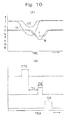
- the timing sensor 190 has the functions of outputting an operation start timing signal CTS ( Figure 10(B)) of the driving system 198 of the canceller 196.
- the timing sensor 190 is disposed immediately downstream of the sensor device 142, and is fixed to the guide rail 116 through a bracket 202.
- the timing sensor 190 is a transmission type photoelectric sensor 204, which is opposedly disposed by sandwiching the rolling passage 122.
- An optical axis of the transmission type photoelectric sensor 204 is disposed close to the guide rail 116, and when the token 104 continuously rolls along, it is set to be positioned in a triangular space 206 ( Figure 9(B)) formed within the peripheral surface of the token 104.
- the timing sensor 190 in place of the timing sensor 190, the falling signal of the thickness sensor 148 or the material sensor 150 may be used. However, since the length from the canceller 196 becomes long, the timing sensor 190 is preferably used.
- the fixed main body 192 has the functions of defining one side surface of the rolling passage 122 and supporting the movable guide 194.
- the fixed main body 192 is in the shape of a rectangular plate, and is disposed integrally with the first main body 152 on the downstream side of the guide rail 116, and its lower end portion is fixed to the guide rail 116.
- the side surface 210 is in the shape of a flat plate, and defines one side surface of the rolling passage 122.
- the fixed main body 192 can be provided separately from the first main body 152.
- the movable guide 194 has the function of guiding the upper end portion side surface of the token 104 rolling on the rolling passage 122, which is in opposition to the cancel device 144.
- a rectangular ring-shaped movable guide frame 210 is disposed.
- the movable guide frame 210 is integrally provided with the second main body 154 in the present embodiment.
- the movable guide 194 is disposed immediately downstream of the second main body 154, and is biased towards the fixed main body 192 by a spring 234.
- a lower edge 214 of the rectangular opening 212 of the frame 210 is positioned flush against or below the rolling surface 114, and an upper edge 216 is disposed in parallel with the rolling surface 114 slightly upper than the maximum token diameter.
- the upper portion of the frame 210 is provided with bearings 218 and 220 which protrude in the cross sectional direction at a predetermined space.
- the movable guide 194 is a flat plate in the shape of a slender rectangle which extends approximately in parallel with the guide rail 116, and when a movable side surface 222 facing its side surface 210 is at a guide position which is in a normal state, it positions in parallel with the side surface 210, and defines the rolling passage 122.
- Support levers 224 and 226 extend upward from the upper portion of the movable guide 194, and support axes 228 and 230 protruding in the cross-sectional direction from its upper end portion are provided.
- the support axes 228 and 230 are pivotally attached to the bearings 218 and 220, respectively.
- the support axes 228 and 230 are positioned on the extension of the movable side surface 222 of the movable guide 194, and moreover, are disposed at a position spaced from the rolling passage 122.
- the movable guide 194 receives a biasing force clockwise by a predetermined force in Figure 5(C) by biasing means 230.
- the biasing means 230 is a spring 234, which is wound around a columnar protrusion 232 protruding in the cross-sectional direction from the frame 210.
- This spring 23 when the token 104 drops from the rolling surface 114 by the canceller 196 and collides against a stopper 200 to be described later, preferably sets a spring force such that a sudden movement of the upper end portion of the contacted token 104 on the way to drop is damped.
- the token 104 dropped approximately directly below is piled up on the spot or returned to a return port through an opening formed at the dropping position.
- the biasing means 230 is replaceable by an actuator of a bob type, a pressure gas type, and the like in addition to the spring 234.
- the canceller 196 has the function of removing a token 104 rolling along the rolling passage 122 of the canceller device 144 from the rolling passage 122.
- the canceller 196 has the function of dropping the token 104 rolling along the rolling surface 114 from the rolling surface 114.
- the canceller 196 is an L-shaped cancel lever 242, which is pivotally supported by a pivot axle 240 ( Figure 6) extending vertically against the rolling surface 114 in the lateral side of the rolling surface 114.
- the pivot axle 240 is fixed to a bearing (not shown) provided at the back surface of the fixed main body 192.
- the cancel lever 242 is formed directly above the rolling surface 114 of the fixed main body 192, and is movably disposed in parallel with the rolling surface 114 in a rectangular passage hole 246 extending in parallel with the rolling surface 114.
- the guide surface 248 of the cancel lever 242 extends from the upstream side of the rolling passage 122 to the downstream side, and moreover, extends in parallel with the rolling surface 114.
- cancel lever 242 is reciprocatable in the direction orthogonal to the rolling passage 122.
- the guide surface 248, when positioned at a waiting position, is flush-mounted with the side surface 210 of the fixed main body 192 or slightly receded into the passage hole 246.
- the token 104 having rolled along the rolling passage 122 is guided in the direction to cross the rolling surface 114 by this guide surface 248, and therefore, it is deviated from the rolling passage 122, and drops from the guide rail 116.
- the canceller 196 has a driven lever 250 extending in the direction vertical to the cancel lever 242, and the driven lever 250 is formed with a long hole 252.
- the driving system 198 has the functions of moving the canceller 196 to a cancel position and moving the canceller 196 located at a cancel position to a standby position.
- the driving system 198 is fixed at the back surface of the fixed body 192.
- the driving system 198 includes an actuator 254 ( Figure 5A).
- a pin 258 at the top end of an output axle 256 of the actuator 254 is slidably inserted into the long hole 252.
- the actuator 254 is an electromagnetic solenoid 260 in the present embodiment, and the output axle 256 is an iron core 262.
- the iron core 262 When the solenoid 260 is demagnetized, the iron core 262 is moved to the right by a return spring 264 acting upon the iron core 262, and moves the cancel lever 242 to a stand by position.
- the stopper 200 has the function of making a position of the token 104 which is deviated from the rolling passage 122 and dropped and collided as a predetermined position.
- the stopper 200 is disposed downstream of the opening 212 and at the lateral side of the rolling passage 122, and is fixed to the frame 210.
- the stopper 200 is preferably formed of hard rubber or other resilient material having elasticity and abrasion resistance and the like in order to reduce a rebound of the token 104.
- the passing sensor 266 includes a light emitting and receiving device 267 fixed to the fixed main body 192 and a prism 268 fixed to the frame 210.
- the crossing position of the emitted light is a position in the vicinity of the rolling surface 114, and is disposed at a position interrupted by all the tokens 104 passing through the selecting portion.
- the passing sensor 266 When the light receiving portion of the light emitting and receiving device 267 is interrupted by the token 104 and does not receive the light, the passing sensor 266 outputs a token passing signal CS.
- the game machine performs a predetermined processing based on this token passing signal CS.
- control device 270 will be described with reference to Figure 7.
- the control device 270 has the functions of discriminating the authenticity of the inputted token 104 based on the detection signal from each sensor 146, 148, and 150, and operating the driving system 198 based on the timing signal from the timing sensor 190 when it is a false token, and removing the false token from the rolling passage 122 and dropping it from the guide rail 116.
- the diameter sensor 146 has coils 280 and 282, and these coils 280 and 282 are cumulatively connected, and are connected to an oscillation circuit 284.
- the oscillation circuit 284 is set to a low frequency, and is connected to a microprocessor 300 through a detection circuit 286 and an AD conversion circuit 288.
- the coil 178 of the thickness sensor 148 includes coils 302 and 304, and these coils 302 and 304 are differentially connected, and are connected to an oscillation circuit 306.
- the oscillation circuit 306 is connected to the microprocessor 300 through a detection circuit 308 and an AD conversion circuit 310,
- the oscillation frequency of the oscillation circuit 31 is set to a high frequency.
- the coil 182 of the material sensor 150 includes coils 312 and 314, and these coils 312 and 314 are cumulatively connected, and are connected to an oscillation circuit 316.
- the oscillation circuit 316 is connected to the microprocessor 300 through a detection circuit 318 and an AD conversion circuit 320.
- the oscillation circuit 316 is set to a low frequency.
- the microprocessor 300 includes a CPU 322, a ROM 324 and a RAM 326.
- the CPU 322 communicates with the RAM 326 based on a program stored in the ROM 324, and performs the discrimination of the authenticity of the token 104 compared with the data of a reference value setting device 328, and in the case of a false token, excites the solenoid 260 for a predetermined time.
- This excitation is performed for a short time so that it can be cancelled also when the token 104 continuously rolls on.
- the excitation can be continuously performed.
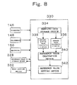
- the reference value setting device 330 is configured by software in the microprocessor 300, for the convenience of explanation, a description will be made by referring to the block diagram shown in Figure 8.
- the reference value setting device 330 includes a mode setting switch 332 which is the selection reference value obtaining mode setting means, a sampling data storing device 334 which is the storage means, an average value calculation device 336, a maximum-minimum value calculation device 338, a reference value calculation device 340 which is calculating means, and a reference value setting device 342.
- the mode setting switch 332 is a switch that switches a reference value setting mode to a selection mode.
- the authenticity of the token 104 is discriminated based on the detection data of each sensor 146, 148, and 150, and in the case of the false token 104, it is cancelled by the canceller 196.
- the detection data from each sensor 146, 148, 150 of the predetermined number of pieces of the tokens is sampled and stored, and when the predetermined number of pieces of the tokens 104 is inputted, based on the average value and the maximum-minimum value of these data, the predetermined reference value is calculated, and after that, it is stored in the reference value storage device 326 by the reference value setting device 342.
- the sampling data storage device 334 has the functions of storing the sampling data obtained by the diameter sensor 146, the thickness sensor 148 and the material sensor 150 for every input of the token 104 in the reference value setting mode.
- the average value calculation device 336 has the functions of calculating the average value regarding the diameter, thickness, and material based on the sampling data stored in the sampling data storage device 334 when the predetermined number of pieces of the token 140 is inputted.
- the maximum-minimum calculation device 338 has the functions of calculating the maximum value and the minimum value of the diameter, thickness, and material, respectively, based on the sampling data stored in the storage device 336 when the same predetermined number of pieces of the token as the average value calculation device 336 is inputted.
- the reference value calculation device 340 has the functions of performing a predetermined processing based on the calculation results of the average value calculation device 336 and the maximum and minimum calculation device 338 and calculating a reference value.
- the reference value calculated by the reference value calculation device 340 is newly stored in the reference value storage circuit 328 by the reference value setting device 342.
- the mode setting switch 332 is switched over to the selection mode and the game machine is put into a playable state.
- the reference value is set by the average value and the maximum-minimum value
- the true token deviated from the average value has a predetermined relationship with the maximum value and the minimum value, the token is not cancelled, but is accepted.
- the true or authentic token 104 deviated from the average value is cancelled, and no smooth game can be performed, but when the maximum value and the minimum value are added so as to set a reference value, even if the token is deviated from the average value, when it has a predetermined relationship with the maximum-minimum values, there is the advantage that the token is discriminated as a true token and the game machine can be operated without causing any sense of discomfort to the client.
- Figure 9 represents an example in which a large diameter false token 104L is inputted first, and then, two true tokens 104T are inputted continuously or sequentially.
- Each token 104 rolls along the rolling surface 114, and after having passed the sensor device 142, reaches the cancel device 144.
- the token 104 is in opposition to the diameter sensor 146 as shown in Figure 9, and then, in opposition to the thickness sensor 148 and the material sensor 150.
- This analogue signal is transmitted to the microprocessor 300 similarly as described above.
- the magnetic fields of the thickness sensor 148 and the material sensor 150 are affected by the token 104.
- This output is converted into a digital signal by the AD conversion circuit 310, and is transmitted to the microprocessor 300.
- This output is converted into a digital signal by the AD conversion circuit 320, and is transmitted to the microprocessor 300.
- the output (line D) of the diameter sensor 146 is compared with the reference value of the reference value storage device 326.
- the processing proceeds to a second step, and when the output is outside the reference value, a cancel signal is outputted.
- the output (line T) of the thickness sensor 148 is compared with the reference value, and when it is outside the reference value, the cancel signal is outputted, and when it is within the reference value, the processing proceeds to a third step.
- the output (line M) of the material sensor 150 is compared with the reference value, and when it is outside the reference value, the cancel signal is outputted, and when it is within the reference value, it is discriminated as the true token for the first time.
- the driving system 198 of the cancel device 196 is not operated.
- the solenoid 260 is not excited.
- the passing signal CS is outputted.
- the control device 270 excites the solenoid 260 for a predetermined time T2 after a predetermined time T1 from the fall of the token signal CTS from the timing sensor 190.
- the cancel lever 242 protrudes into the rolling passage 122 or pushes the side surface of the token 104 rolling on the rolling surface 114.
- the false token 104L is deviated from the rolling passage 122, and drops from the guide rail 116.
- the dropped false token 104L drops obliquely by inertia force, and collides against the stopper 200.
- the upper portion of the false token 104L is positioned at the rolling passage 122.
- the upper portion of the false token 104L is guided by the movable side surface 222 of the movable guide 194 and the side surface 210 of the fixed main body 192.
- the true token 104T rolls on by continuously following the false token 104L, and when its return movement to the stand-by position of the cancel lever 242 is delayed, the upper end portion of the true token 104T is guided by the movable guide 194, and therefore, it is hard to drop.
- the dropped false token 104L is either accumulated immediately below or returned to a return port by passing through a passage (not shown).
- the mode setting switch 332 is set to the reference value setting mode and a predetermined number of pieces of new token is inputted, so that a new reference value is automatically prepared and stored in the reference value storage device 326.
- the clocking of the predetermined time T1 in the control device 270 can be started from the rise signal of the token signal CTS.
- predetermined times T1 and T2 are automatically selected and set from a storage table according to the token size.
- Figure 11 is a cross-sectional view of a second embodiment which is equivalent to Figure 2 in the first embodiment.
- the second embodiment is an example of a selecting device that can obtain characteristics regarding the token at high accuracy.
- a guide rail 116 is configured by a first inclined surface 352 protruding downward to a second main body 154 formed at the lower end portion of the first main body 152, and a second inclined surface 354 protruding upward to the first main body 152 formed at the lower end portion of the second main body 154.
- a rolling surface 114 of the token 104 is configured by the first inclined surface 352 and the second inclined surface 354.
- the first inclined surface 352 is an inclined surface that connects the side surface 153 of the first main body 152 and a space protrusion 160, and is inclined approximately at an angle of 60 degrees for the horizontal line.
- the second inclined surface 354 is an upper surface of the protrusion 356 that slightly protrudes to the lateral direction from the side surface 155 of the second main body 154, and is inclined approximately at an angle of 60 degrees for the horizontal line.
- first inclined surface 352 and the second inclined surface 354 are symmetrically disposed by sandwiching a rowing passage 122.
- the width of the rolling passage 122 is defined by the side surface 153 of the first main body 152 and the side surface 155 of the second main body 154, and is set slightly larger than the thickness of the token 104 by striking the top end of the space protrusion 160 against the top end of the protrusion 356 of the second main body 154.
- a diameter sensor 146 is disposed on the same straight line vertical to the guide rail 116 away from guide rail 116 rather than a thickness sensor 148 and a material sensor 150.
- the thickness sensor 148, the material sensor 150 and the diameter sensor 146 are in opposition to the token 140 approximately at the same time, and therefore, the information on characteristics regarding the token can be obtained approximately at the same time.
- the length of the sensor device 142 can be made short, and as a result, there is the advantage that a token input device can be made small-sized.
- the token 104 has a left lower end peripheral surface rolled on a second inclined surface 354, and a right lower end peripheral surface rolled on a first inclined surface 352.
- the token 104 rolls on a position where reactive forces from the second inclined surface 354 and the first inclined surface 352 of the left and right are balanced.
- the token 104 passes the center of the rolling passage 122, specifically the center between the side surfaces 153 and 155.
- the lower end of the token 104 is positioned at the center of the sensor units 180.
- the token 104 is positioned at the center of the pair of the left and right sensor units 180, and therefore, the magnetic fluxes generated from the left and right sensors are approximately equally operated, and this leads to the acquisition of highly accurate characteristic information on the token 104, and as a result, highly accurate authenticity discrimination can be performed.
- the thickness sensor as described in the first embodiment, is differentially connected, it is easily affected by a distance between the token 104 and the sensor unit 180.
Applications Claiming Priority (2)
| Application Number | Priority Date | Filing Date | Title |
|---|---|---|---|
| JP2005308760 | 2005-10-24 | ||
| JP2006253406A JP5617096B2 (ja) | 2005-10-24 | 2006-09-19 | ゲーム機のメダル投入装置におけるメダル選別装置 |
Publications (2)
| Publication Number | Publication Date |
|---|---|
| EP1777662A1 true EP1777662A1 (fr) | 2007-04-25 |
| EP1777662B1 EP1777662B1 (fr) | 2008-11-26 |
Family
ID=37670655
Family Applications (1)
| Application Number | Title | Priority Date | Filing Date |
|---|---|---|---|
| EP06122698A Expired - Fee Related EP1777662B1 (fr) | 2005-10-24 | 2006-10-20 | Dispositif de manipulation de jeton |
Country Status (7)
| Country | Link |
|---|---|
| US (1) | US20070251799A1 (fr) |
| EP (1) | EP1777662B1 (fr) |
| JP (1) | JP5617096B2 (fr) |
| KR (1) | KR100849700B1 (fr) |
| CN (1) | CN1956014B (fr) |
| AU (1) | AU2006233183A1 (fr) |
| TW (1) | TW200727963A (fr) |
Cited By (1)
| Publication number | Priority date | Publication date | Assignee | Title |
|---|---|---|---|---|
| EP2048630A1 (fr) * | 2007-09-12 | 2009-04-15 | Asahi Seiko Co., Ltd. | Dispositif de traitement de support de valeur |
Families Citing this family (7)
| Publication number | Priority date | Publication date | Assignee | Title |
|---|---|---|---|---|
| JP5354431B2 (ja) * | 2005-10-24 | 2013-11-27 | 旭精工株式会社 | メダル選別装置を有するゲーム機のメダル投入装置 |
| GB2452143B (en) * | 2007-08-21 | 2011-02-16 | Namco Bandai Games Inc | Token game machine |
| JP5109071B2 (ja) * | 2007-09-12 | 2012-12-26 | 旭精工株式会社 | メダル選別手段を有するメダル処理装置 |
| JP6386714B2 (ja) * | 2013-10-18 | 2018-09-05 | 株式会社オーイズミ | 遊技媒体計数機 |
| JP6277350B2 (ja) * | 2014-12-16 | 2018-02-14 | 旭精工株式会社 | 硬貨識別装置 |
| CN106447890B (zh) * | 2016-12-07 | 2022-05-24 | 东北大学 | 一种轨道式硬币分离器 |
| CN111754673A (zh) * | 2020-06-23 | 2020-10-09 | 广州畅阳电子科技有限公司 | 一种硬币循环机 |
Citations (9)
| Publication number | Priority date | Publication date | Assignee | Title |
|---|---|---|---|---|
| US4582189A (en) * | 1984-03-14 | 1986-04-15 | Reed Industries, Inc. | Coin validation apparatus |
| WO1991003032A1 (fr) * | 1989-08-21 | 1991-03-07 | Mars Incorporated | Appareil pour verifier les pieces de monnaie |
| JPH0824434A (ja) * | 1994-07-19 | 1996-01-30 | Universal Hanbai Kk | 遊技機等のコイン選別装置 |
| EP0724237A2 (fr) * | 1995-01-27 | 1996-07-31 | Asahi Seiko Kabushiki Kaisha | Machine pour trier des pièces de monnaie |
| EP0775989A2 (fr) * | 1995-11-21 | 1997-05-28 | Coin Acceptors, Inc. | Dispositif de contrôle de pièces de monnaie et méthode associée |
| EP0974938A2 (fr) * | 1998-07-23 | 2000-01-26 | Microsystems Controls Pty Limited | Sélecteur de pièces de monnaie |
| DE10049390A1 (de) * | 1999-10-06 | 2001-04-12 | Nippon Conlux Co Ltd | Münzinspektionsverfahren und -vorrichtung |
| US20030150688A1 (en) * | 1996-06-28 | 2003-08-14 | Martin Douglas Alan | Coin discrimination apparatus and method |
| EP1345185A1 (fr) * | 2002-03-11 | 2003-09-17 | Asahi Seiko Kabushiki Kaisha | Sélecteur de pièces de monnaie |
Family Cites Families (28)
| Publication number | Priority date | Publication date | Assignee | Title |
|---|---|---|---|---|
| JP3006125B2 (ja) * | 1991-04-10 | 2000-02-07 | 松下電器産業株式会社 | 硬貨識別装置 |
| GB2266400B (en) * | 1991-09-28 | 1995-11-22 | Anritsu Corp | Coin discriminating apparatus |
| JP2766572B2 (ja) * | 1991-12-17 | 1998-06-18 | アルゼ株式会社 | コインセレクタの不正検出装置 |
| US5971128A (en) * | 1994-09-09 | 1999-10-26 | Mars, Incorporated | Apparatus for validating items of value, and method of calibrating such apparatus |
| JPH09128583A (ja) * | 1995-11-06 | 1997-05-16 | Tamura Electric Works Ltd | 硬貨選別装置 |
| JP3867111B2 (ja) * | 1997-05-26 | 2007-01-10 | 旭精工株式会社 | 円板体の判別装置 |
| GB2331614A (en) * | 1997-11-19 | 1999-05-26 | Tetrel Ltd | Inductive coin validation system |
| JP3386355B2 (ja) * | 1997-12-22 | 2003-03-17 | ローレルバンクマシン株式会社 | 硬貨処理機 |
| JP2000187746A (ja) * | 1998-12-22 | 2000-07-04 | Canon Electronics Inc | 硬貨選別装置 |
| JP4423704B2 (ja) * | 1999-07-02 | 2010-03-03 | 株式会社セガ | メダルプッシャゲーム装置 |
| JP2001175913A (ja) * | 1999-12-20 | 2001-06-29 | Tamura Electric Works Ltd | 硬貨処理装置 |
| US7635059B1 (en) * | 2000-02-02 | 2009-12-22 | Imonex Services, Inc. | Apparatus and method for rejecting jammed coins |
| US6667615B2 (en) * | 2000-02-10 | 2003-12-23 | Sankyo Seiki Mfg. Co., Ltd. | Coin identifying device using magnetic sensors |
| DE10042167C1 (de) * | 2000-08-17 | 2002-04-04 | Trenner D Wh Muenzpruefer | Mechanischer Münzprüfer mit Sperrklinke |
| JP4143711B2 (ja) * | 2000-08-30 | 2008-09-03 | 旭精工株式会社 | コインセンサのコア |
| JP3547125B2 (ja) * | 2001-02-21 | 2004-07-28 | 株式会社オリンピア | メダルセレクタ |
| JP3481211B2 (ja) * | 2001-02-27 | 2003-12-22 | コナミ株式会社 | メダル遊技機 |
| JP4085585B2 (ja) * | 2001-03-06 | 2008-05-14 | オムロン株式会社 | 投入メダル選別装置 |
| SE522752C2 (sv) * | 2001-11-05 | 2004-03-02 | Scan Coin Ind Ab | Metod att driva en myntdiskriminator och en myntdiskriminator där påverkan på spolorgan mäts när mynt utsätts för magnetfält alstrade av spolorgan utanför myntet |
| JP2004008503A (ja) * | 2002-06-07 | 2004-01-15 | Kato Seisakusho:Kk | プッシャーゲーム機 |
| JP4334192B2 (ja) * | 2002-08-22 | 2009-09-30 | ローレル精機株式会社 | 硬貨処理機 |
| JP3759923B2 (ja) * | 2002-11-18 | 2006-03-29 | 株式会社オリンピア | 遊技機及び遊技機における不正行為防止方法並びにプログラム |
| CN1795470A (zh) * | 2003-05-22 | 2006-06-28 | 日本功勒克斯股份有限公司 | 货币金属处理装置及其控制方法 |
| JP4324414B2 (ja) * | 2003-07-11 | 2009-09-02 | オムロン株式会社 | 投入メダル選別装置の接合構造 |
| JP2005177449A (ja) * | 2003-11-28 | 2005-07-07 | Olympia:Kk | スロットマシン及び遊技機 |
| JP4257265B2 (ja) * | 2004-01-29 | 2009-04-22 | 株式会社オリンピア | 遊技機 |
| JP4026769B2 (ja) * | 2004-02-05 | 2007-12-26 | 株式会社タイトー | メダルプッシャーゲーム機のメダルシューター装置 |
| JP5354431B2 (ja) * | 2005-10-24 | 2013-11-27 | 旭精工株式会社 | メダル選別装置を有するゲーム機のメダル投入装置 |
-
2006
- 2006-09-19 JP JP2006253406A patent/JP5617096B2/ja active Active
- 2006-10-13 TW TW095137698A patent/TW200727963A/zh not_active IP Right Cessation
- 2006-10-20 EP EP06122698A patent/EP1777662B1/fr not_active Expired - Fee Related
- 2006-10-20 KR KR1020060102222A patent/KR100849700B1/ko not_active IP Right Cessation
- 2006-10-23 CN CN2006101356964A patent/CN1956014B/zh not_active Expired - Fee Related
- 2006-10-23 US US11/551,837 patent/US20070251799A1/en not_active Abandoned
- 2006-10-24 AU AU2006233183A patent/AU2006233183A1/en not_active Abandoned
Patent Citations (9)
| Publication number | Priority date | Publication date | Assignee | Title |
|---|---|---|---|---|
| US4582189A (en) * | 1984-03-14 | 1986-04-15 | Reed Industries, Inc. | Coin validation apparatus |
| WO1991003032A1 (fr) * | 1989-08-21 | 1991-03-07 | Mars Incorporated | Appareil pour verifier les pieces de monnaie |
| JPH0824434A (ja) * | 1994-07-19 | 1996-01-30 | Universal Hanbai Kk | 遊技機等のコイン選別装置 |
| EP0724237A2 (fr) * | 1995-01-27 | 1996-07-31 | Asahi Seiko Kabushiki Kaisha | Machine pour trier des pièces de monnaie |
| EP0775989A2 (fr) * | 1995-11-21 | 1997-05-28 | Coin Acceptors, Inc. | Dispositif de contrôle de pièces de monnaie et méthode associée |
| US20030150688A1 (en) * | 1996-06-28 | 2003-08-14 | Martin Douglas Alan | Coin discrimination apparatus and method |
| EP0974938A2 (fr) * | 1998-07-23 | 2000-01-26 | Microsystems Controls Pty Limited | Sélecteur de pièces de monnaie |
| DE10049390A1 (de) * | 1999-10-06 | 2001-04-12 | Nippon Conlux Co Ltd | Münzinspektionsverfahren und -vorrichtung |
| EP1345185A1 (fr) * | 2002-03-11 | 2003-09-17 | Asahi Seiko Kabushiki Kaisha | Sélecteur de pièces de monnaie |
Non-Patent Citations (1)
| Title |
|---|
| DATABASE WPI Week 199614, Derwent World Patents Index; AN 1996-133833, XP002419366 * |
Cited By (1)
| Publication number | Priority date | Publication date | Assignee | Title |
|---|---|---|---|---|
| EP2048630A1 (fr) * | 2007-09-12 | 2009-04-15 | Asahi Seiko Co., Ltd. | Dispositif de traitement de support de valeur |
Also Published As
| Publication number | Publication date |
|---|---|
| KR100849700B1 (ko) | 2008-07-31 |
| JP5617096B2 (ja) | 2014-11-05 |
| KR20070044360A (ko) | 2007-04-27 |
| US20070251799A1 (en) | 2007-11-01 |
| AU2006233183A1 (en) | 2007-05-10 |
| TWI321061B (fr) | 2010-03-01 |
| TW200727963A (en) | 2007-08-01 |
| CN1956014B (zh) | 2011-12-21 |
| CN1956014A (zh) | 2007-05-02 |
| EP1777662B1 (fr) | 2008-11-26 |
| JP2007144126A (ja) | 2007-06-14 |
Similar Documents
| Publication | Publication Date | Title |
|---|---|---|
| EP1777662B1 (fr) | Dispositif de manipulation de jeton | |
| AU604478B2 (en) | Tokens and apparatus for handling tokens | |
| US5379875A (en) | Coin discriminator and acceptor arrangement | |
| EP1901240B1 (fr) | Dispositif de traitement de support de valeur | |
| US7946407B2 (en) | Value medium processing apparatus | |
| JP5066674B2 (ja) | コインセレクタ | |
| JP2009193375A5 (fr) | ||
| JP2008117072A5 (fr) | ||
| JP5354431B2 (ja) | メダル選別装置を有するゲーム機のメダル投入装置 | |
| JP2013003673A5 (fr) | ||
| JP2013003673A (ja) | コインセレクタ | |
| JP5299761B2 (ja) | Icコインゲーム機 | |
| GB2055498A (en) | Coin selection device | |
| JP5309965B2 (ja) | 価値媒体処理装置 | |
| JP5109072B2 (ja) | 価値媒体処理装置 | |
| JP2010119757A5 (fr) | ||
| US8827776B1 (en) | Coin sensor arrangement for coin processing machine | |
| JP6707744B2 (ja) | 円盤体検知装置 | |
| JP4608369B2 (ja) | 硬貨識別装置 | |
| KR200324817Y1 (ko) | 완충기를 포함하는 주화 선별기 | |
| KR101028446B1 (ko) | 가치 매체 처리 장치 | |
| JP5568802B2 (ja) | コイン選別装置 | |
| JP5608898B2 (ja) | コイン識別装置 | |
| JP5163979B2 (ja) | 価値媒体処理装置及びそれに用いるicコイン | |
| JP5636030B2 (ja) | 棒金収納庫 |
Legal Events
| Date | Code | Title | Description |
|---|---|---|---|
| PUAI | Public reference made under article 153(3) epc to a published international application that has entered the european phase |
Free format text: ORIGINAL CODE: 0009012 |
|
| AK | Designated contracting states |
Kind code of ref document: A1 Designated state(s): AT BE BG CH CY CZ DE DK EE ES FI FR GB GR HU IE IS IT LI LT LU LV MC NL PL PT RO SE SI SK TR |
|
| AX | Request for extension of the european patent |
Extension state: AL BA HR MK YU |
|
| 17P | Request for examination filed |
Effective date: 20071017 |
|
| 17Q | First examination report despatched |
Effective date: 20071115 |
|
| AKX | Designation fees paid |
Designated state(s): GB IT |
|
| REG | Reference to a national code |
Ref country code: DE Ref legal event code: 8566 |
|
| GRAP | Despatch of communication of intention to grant a patent |
Free format text: ORIGINAL CODE: EPIDOSNIGR1 |
|
| GRAS | Grant fee paid |
Free format text: ORIGINAL CODE: EPIDOSNIGR3 |
|
| GRAA | (expected) grant |
Free format text: ORIGINAL CODE: 0009210 |
|
| AK | Designated contracting states |
Kind code of ref document: B1 Designated state(s): GB IT |
|
| REG | Reference to a national code |
Ref country code: GB Ref legal event code: FG4D |
|
| PLBE | No opposition filed within time limit |
Free format text: ORIGINAL CODE: 0009261 |
|
| STAA | Information on the status of an ep patent application or granted ep patent |
Free format text: STATUS: NO OPPOSITION FILED WITHIN TIME LIMIT |
|
| 26N | No opposition filed |
Effective date: 20090827 |
|
| PGFP | Annual fee paid to national office [announced via postgrant information from national office to epo] |
Ref country code: GB Payment date: 20151021 Year of fee payment: 10 Ref country code: IT Payment date: 20151028 Year of fee payment: 10 |
|
| GBPC | Gb: european patent ceased through non-payment of renewal fee |
Effective date: 20161020 |
|
| PG25 | Lapsed in a contracting state [announced via postgrant information from national office to epo] |
Ref country code: GB Free format text: LAPSE BECAUSE OF NON-PAYMENT OF DUE FEES Effective date: 20161020 |
|
| PG25 | Lapsed in a contracting state [announced via postgrant information from national office to epo] |
Ref country code: IT Free format text: LAPSE BECAUSE OF NON-PAYMENT OF DUE FEES Effective date: 20161020 |