EP1772414A1 - Chasse-pieds pliable auto-bloquant pour cabine d'ascenseur - Google Patents
Chasse-pieds pliable auto-bloquant pour cabine d'ascenseur Download PDFInfo
- Publication number
- EP1772414A1 EP1772414A1 EP06020283A EP06020283A EP1772414A1 EP 1772414 A1 EP1772414 A1 EP 1772414A1 EP 06020283 A EP06020283 A EP 06020283A EP 06020283 A EP06020283 A EP 06020283A EP 1772414 A1 EP1772414 A1 EP 1772414A1
- Authority
- EP
- European Patent Office
- Prior art keywords
- car
- skirt
- apron
- elements
- safety system
- Prior art date
- Legal status (The legal status is an assumption and is not a legal conclusion. Google has not performed a legal analysis and makes no representation as to the accuracy of the status listed.)
- Granted
Links
- 230000001681 protective effect Effects 0.000 claims description 33
- 238000012806 monitoring device Methods 0.000 claims description 2
- 230000000284 resting effect Effects 0.000 claims 1
- 238000010276 construction Methods 0.000 description 13
- 230000006378 damage Effects 0.000 description 3
- 239000004744 fabric Substances 0.000 description 3
- 238000013459 approach Methods 0.000 description 2
- 230000035515 penetration Effects 0.000 description 2
- 229920000271 Kevlar® Polymers 0.000 description 1
- 239000004677 Nylon Substances 0.000 description 1
- 208000027418 Wounds and injury Diseases 0.000 description 1
- 238000005452 bending Methods 0.000 description 1
- 239000000872 buffer Substances 0.000 description 1
- 108010066057 cabin-1 Proteins 0.000 description 1
- 239000004568 cement Substances 0.000 description 1
- 230000000694 effects Effects 0.000 description 1
- 239000012530 fluid Substances 0.000 description 1
- 239000003365 glass fiber Substances 0.000 description 1
- 230000005484 gravity Effects 0.000 description 1
- 208000014674 injury Diseases 0.000 description 1
- 238000009434 installation Methods 0.000 description 1
- 239000004761 kevlar Substances 0.000 description 1
- 239000000463 material Substances 0.000 description 1
- 239000002184 metal Substances 0.000 description 1
- 229920001778 nylon Polymers 0.000 description 1
- 239000004033 plastic Substances 0.000 description 1
- 230000002028 premature Effects 0.000 description 1
- 238000009418 renovation Methods 0.000 description 1
- 238000009420 retrofitting Methods 0.000 description 1
Images


Classifications
-
- B—PERFORMING OPERATIONS; TRANSPORTING
- B66—HOISTING; LIFTING; HAULING
- B66B—ELEVATORS; ESCALATORS OR MOVING WALKWAYS
- B66B13/00—Doors, gates, or other apparatus controlling access to, or exit from, cages or lift well landings
- B66B13/24—Safety devices in passenger lifts, not otherwise provided for, for preventing trapping of passengers
- B66B13/28—Safety devices in passenger lifts, not otherwise provided for, for preventing trapping of passengers between car or cage and wells
- B66B13/285—Toe guards or apron devices
Definitions
- the invention relates to a safety system for a lift with a car apron according to the preamble of claim 1.
- Such safety systems with a car apron provide protection in case passengers have to be released from a car stuck in the area of a floor opening, at a distance from the inherent stopping position. In such a case, a more or less large gap between the lower edge of the car floor and the top of the floor ceiling opens up.
- the people to be evacuated will usually sit on the car floor and then let their legs out of the car until they come to a stop on the floor. There is now the danger that these people come in reserve and crash through the gap between the bottom of the car and the top of the floor ceiling in the shaft.
- the car apron of such a safety system must have a considerable length in the vertical direction.
- the relevant standards usually require a length of not less than 750 mm.
- the DE 203 13 911 designed in the manner of a scissor lattice, telescoping in the vertical direction grid as a car apron.
- a grid is not only expensive, but also problematic from a stability point of view, since numerous pivot points are to be realized.
- the grid which can not be supported backwards (seen from the shaft door opening) in the shaft-facing direction, must be very rigid in itself. Sufficiently rigid, so as not to give way, even if at its lowest end there is a large, approximately horizontally - inward direction To attack forces, as they occur in the worst case, when a person falls in the bay towards the bottom of the grid.
- relatively heavy and stable structures are required, which not only unnecessarily limit the payload of the car, but also expensive to wear and only with considerable effort to use, in particular to catch up again.
- This construction has two disadvantages. Firstly, the apron is not blocked in its protective position. That is, it can not be ruled out that the skirt is pushed aside by the action of stronger forces acting approximately horizontally in the shaft-wise direction. For example, in situations where a passenger tries to descend from a car stuck high above the floor ceiling onto the floor, thereby losing his balance and falling backwards against the apron in the direction of the shaft.
- a foldable car apron known ( Figure 3b).
- This car apron is formed so that it consists of two sheet-like elements which are hinged together at the extreme ends of their opposite horizontal edges by means of hinges.
- the first lowermost plate is provided with a lower transverse strut, which in turn is connected by means of longitudinal struts with a four-bar linkage.
- the second, the car floor near sheet metal is pivotally hinged to the car in an area below the car door sill.
- the construction is designed so that the two plates forming the actual car apron do not come to rest either completely or approximately in one plane or parallel to one another in adjacent planes, even in the protective position.
- the four-bar linkage used here ensures that the two plates forming the actual car apron can not "make long", but always have a certain angular position relative to each other and thus ensure that the plates can be folded together when the apron touches the shaft bottom.
- This construction has several disadvantages. On the one hand leads to a penetration permitting opening of this construction to the dangers.
- this construction is not completely harmless because it is not locked and in particular is not self-locking. That's crucial. Because it is again so that a person who has emerged from the car with the feet on the floor during the emergency exit and at this moment loses its balance and falls unhappy back against the car apron, the car apron can push aside a considerable amount aside ,
- this construction although the actual car apron plates forming folds claimed considerable space under the car floor. This is because the inboard tie bar between the four-bar link and the bottom plate of the car apron is approximately as long as the two panels of the car apron are in their unfolded position Position. Therefore, the construction requires significantly more space under the car floor, as required by the two folded plates per se.
- the invention is based on the object to provide a safety system with a movable car apron, which offers improved protection in protection position and opens the possibility to have to keep free for the rest position only less area under the car.
- the safety system has means by means of which the foldable skirt elements can be locked in their protective position in such a way that they are not moved relative to one another by forces acting on one or more skirt elements from the outside and in the bay-like, substantially horizontal direction. can still be pivoted together in the bay direction. Smaller, z. B. certain elasticity relative movements to each other or in total shaft inward, are uncritical and therefore allow.
- the locking means are self-locking, d. H. a force acting in the opening direction locks the locking means against opening, so that the force acting in the opening direction can be arbitrarily large without it being feared that the locking will yield (as long as no component destruction occurs).
- an advantageous development provides that the axis around which the guide or locking means are pivotally mounted on one of the skirt elements, seen in the vertical direction, between the axis is about which the car next apron element pivotally hinged to the car, and the axis that connects the skirt elements relative to each other.
- Such an axial position allows in a particularly simple manner an effective, because preferably self-locking locking the skirt elements.
- the skirt elements are hinged to each other so that on a skirt element, the common pivot axis is disposed away from its nearest horizontal edge, so that the portion of this apron element which extends between the common pivot axis and the horizontal edge, forms a lever arm with respect to the common pivot axis on which the guiding or locking means engage.
- This lever arm allows a self-locking blockage of the two skirt elements.
- the guiding and / or locking means comprise at least one pull or push rod, which is foldable in itself. This reduces the space requirement under the car in rest position, since then occupy not only the apron, but also the draft or push rods used for the construction of little space.
- the guiding and / or locking means comprise at least one telescopic actuating member.
- the skirt elements extend in their protective position in a plane or substantially parallel to one another along two directly adjacent planes, so that they form a substantially flat overall surface.
- Such a design makes it possible to control the gap between the car apron and the upper edge of the respective one Floor ceiling to keep largely constant small.
- the risk of pinching is even lower than when using a skirt with a "kink", ie an apron, the skirt elements are arranged more than slightly angularly to each other.
- a further preferred embodiment provides that the skirt elements are held in its rest position by another locking means under the car floor so that they automatically pivot in the protective position and lock there when the lock of said further locking means is deactivated. Such an embodiment ensures that even with sudden power outages, which have the consequence of a subsequent emergency exit of the passengers result, the apron elements are reliably placed in their protective position.
- a monitoring device is provided, by means of which it can be detected whether the apron elements properly assume their rest position after their use and release the ride only when that is the case, so putting on is prevented.
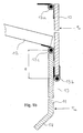
- Fig. 1a shows a 2: 1 suspended in a traction drive pulley elevator with its main components
- the elevator is shown as such only schematically and is used in the representation chosen here only as an example - the invention can equally be used in quite different types of elevators including hydraulic lifts.
- the elevator consists of an elevator car 1, which runs along the guide rails, not shown, the shaft 2 along.
- a traction sheave drive 3 is provided between the area traveled by the cabin or its extensions upward and the shaft wall, which is here, purely by way of example, designed as a drive with so-called double wrap.
- the support cable 4 runs on one side to the cabin, is by means of pulleys 5 passed under the cabin 1 and runs on the other side back up into the shaft head where the support cable is fixed (not shown here).
- the support cable 4 runs from the drive to the counterweight 6, which may possibly also be suspended in a bottle (not shown here).
- FIG. 1a The illustration selected from Fig. 1a shows the situation that the car has kept unscheduled in the shaft, for example due to a power failure or damage to the traction sheave drive.
- the car 1 is therefore only partially in front of the shaft door opening 6.
- the passengers are released from the car by the car doors are opened manually.
- the passengers sat in such a situation, at least if a greater height difference to the floor floor is overcome, i. d. R. on the threshold of the car door and can then slide down along the arrow P with his feet to the floor floor 7.
- the safety system which will be explained in more detail below, consists of a car apron 9 with two largely rigid apron elements 10 and 11 and the movement of these apron elements guiding elements in the form of a linkage comprising two articulated levers 12.
- the two skirt elements 10 and 11 are here in their so-called protective position, d. H. they depend vertically oriented, so largely vertically extending from the bottom of the car compartment down (with minor deviations from the vertical are harmless, a fully vertical orientation is desired).
- the two skirt elements 10, 11 are locked in their protection position - the skirt elements can not be moved relative to each other or jointly in the shaft direction by forces acting from the shaft door opening in the baywise and substantially horizontal directions on one or both of the skirt elements 10, 11 be panned. Being remarkable is that there is a self-locking lock - the attack of said forces causes the skirt elements are held even more firmly in their protective position. In order to bring the skirt elements out of their protective position, the larger the said forces acting in the horizontal-bayward direction, the greater are the greater the forces required.
- FIG. 1b shows a detail of the safety system shown in FIG. 1a, namely the area in which the two skirt elements 10 and 11 are hinged to one another and the second skirt element 11 is articulated to the articulated lever 12.
- first apron element 10 Shown here is a first apron element 10, which is articulated by means of the hinge 13a in the region near the threshold of the elevator car pivotally mounted on the elevator car.
- the first skirt element 10 is largely rigid in itself.
- this apron element is formed from a full-surface sheet, although admittedly allows certain twists, but does not yield significantly, so in itself is largely rigid.
- this apron element can also be formed, for example, by a circumferential, substantially rigid apron element frame, which is planked or tightly covered with a suitable material, for example a plastic plate, a Kevlar fabric or thick nylon fabric or a glass fiber fabric.
- skirt element has no larger openings which are accessible from the shaft door opening, when the skirt element is in the protective position. Any larger openings, ie openings that allow penetration of whole body parts, represent a source of potential injury.
- first skirt element 10 the same design options are open as for the first skirt element 10.
- both skirt elements are of similar construction.
- the skirt member 11 is hinged to the first skirt member via a hinge 13b.
- the hinge 13b is there (relative to the protective position) mounted in the vicinity of the lower horizontally oriented end edge of the first skirt member 10.
- the hinge is attached to the further skirt element 11. This, however, at some distance from its (seen in protective position) horizontally aligned upper end edge.
- the articulated lever 12 is articulated via a further hinge 13c, which not only functions as a guide means that controls the folding and unfolding, but also as in its length (between its articulation points under the car and the skirt element 11) variable locking means.
- lever arm H As a result of the just described type of articulation of the articulated lever, the articulation point of the articulated lever 12, based on the axis of the hinge 13b, a lever arm H.
- the length of this lever arm H is to be dimensioned depending on the circumstances of the case.
- the two skirt elements 10 and 11 when in protective position as in this case, essentially form a flat surface - in which the two skirt elements lie parallel to each other in two directly adjacent planes (apart from the deflector slope 14 at the lower end of the lower protective element 11), so that they form substantially a total area, at which even when the elevator is still moving, nothing can get caught, and the an approximately equal gap distance between the apron surface and the top of each floor floor 7 ensures.
- Fig. 1c shows (schematically) the safety system just discussed in its rest position. Preferably, this rest position is always taken when scheduled operation expires.
- the safety device comprises an electric holding magnet 16 mounted on an unspecified carrier. This acts (with respect to the protective position) on the lower portion 12b of the articulated lever 12 and holds it in an approximately horizontal, folded position. It is not necessary (and preferably even waived) that the security system is folded completely flat under the car floor. Rather, the security system can and should not be folded completely flat even when folded, but by a certain amount "Apply" in the vertical direction.
- FIG. 1i shows a section of the articulated lever 12 in the region of the articulation 12c between the upper articulated lever part 12a and the lower articulated lever part 12b.
- the lower articulated lever part 12b is in this case with a stop lug Equipped 12d, which limits the Verschwenkweg the two articulated levers 12a and 12b to each other. It is the case that the articulated lever can only continue to buckle from the position shown here in such a way that the articulation point 12c moves upwards in the direction of the arrow. From this position, it is not possible to bend the articulated lever so that the articulated axle 12c moves downwards, in the opposite direction of the arrow.
- the articulated lever 12 is designed so that the longitudinal axis 12f of the articulated lever part 12b deviates by a few degrees from the longitudinal axis 12e of the upper articulated lever part 12a. In this way, the articulated lever is self-locking in the sense that even when high forces occur in the axial direction of the axle 12c can not be made to emigrate upward in the direction of the arrow.
- the safety device can be unlocked, for example, by a small, possibly closable hole (closable by plugs or the like) is provided in the upper skirt member 10 at a suitable location by the means of a hook rod or other suitable tool from the floor side in the direction of the arrow the buckling lever 12 can be pulled to cause it to buckling. Then both apron elements together with the associated guide means can be brought back into the rest position - manually or with a corresponding device.
- a suitable actuator pneumatic cylinder, motorized threaded rod, linear motor or the like
- a suitable actuator pneumatic cylinder, motorized threaded rod, linear motor or the like
- Figs. 1g and 1h again show the construction of the first embodiment just discussed in three-dimensional view.
- Figs. 2a to 2d show a second embodiment of the invention.
- the two skirt elements 10 and 11 can be hinged to each other in the same way as that shown in FIG. 1b for the previous embodiment.
- Changed here are only the guiding and locking means, which are designed in the form of a pivot lever 120, which consists of two sections, namely its upper portion 120 b and its lower portion 120 a.
- This pivot lever 120 is articulated with its lower portion 120a in the same way as before, hinged to the lower skirt member 11.
- the upper portion 120 b of the pivot lever 120 is guided horizontally displaceable in linear guides 16.
- an actuating member in the form of a linear drive 121 is articulated at the lower portion 120a of the pivoting lever 120 in the second exemplary embodiment shown concretely here.
- This linear drive 121 makes it possible to bring the skirt elements 10, 11 at any desired time from its rest position to its protective position, and vice versa.
- This variant is therefore particularly suitable for elevator systems in which a premature opening of the shaft doors should be made, and therefore the apron must remain in protective position even during regular operation until the car anograph the lowest stop where the apron must be retracted for reasons of space .
- the construction is, as is preferred, designed so that the linear drive, for example because its piston rod is retracted against the force of a spring, even in a power failure, ie when no supply voltage is available, the skirt elements 10, 11 automatically in its protective position bring where they lock. A locking takes place because the lower portion 120a of the pivot lever 120 articulated on both sides is. Due to this, it can not transmit compressive forces in the horizontal direction.
- this portion 120a of the pivot lever 120 tries to go even further in a vertical orientation, if it is loaded from the outside with forces acting in the horizontal direction.
- the linear guides 16 so to speak, the lower and the upper section of the pivot lever "wedge" and thus lock automatically or ideally self-locking.
- the linear guides are designed so that no automatic or self-locking locking takes place, means should be used to ensure locking externally. For example, it makes sense to use the linear drive for locking and / or provide further means (such as spring-biased locking pins which engage corresponding recesses of the pivot lever 120), which prevent the upper portion 120b of the pivot lever continue to move in the linear guides 16 and can dodge.
- Fig. 2d is shown how the blockade can be canceled again if you want to go to the regular operating state.
- a small, possibly closed by a stopper opening provided, can be inserted through the means of a suitable push rod, the upper part 120a of the pivot lever 120 back into its horizontal linear guides ,
- this embodiment can also be modified to the effect that the linear drive 121 is dispensed with.
- locking means are provided which hold the running in the linear guides end 120 b of the pivot lever 120, as long as the skirt elements are to assume their rest position.
- the blockade is released.
- the two skirt elements 10 and 11 fall under their own weight down, unfold and pull the portion 120b of the pivot lever out of its linear guides, so that the skirt elements under the influence of their own weight over the self in Fig. 2b (for the variant with linear drive) shown intermediate position 2c and can lock there, preferably automatically or self-locking, as described above.
- FIGS. 3a to 3d show a third exemplary embodiment. This corresponds, at least as far as the kinematics of the two skirt elements 10 and 11, largely the first embodiment, unless otherwise described below. Only the guiding and locking means are designed differently here. Instead of a buckling lever 12, an actuating member 1200 is used here, which is articulated at the appropriate place as the articulated lever 12 at the lower apron element articulated. At the same time, the two skirt elements 10 and 11 are elastically biased against each other at this point by means of a suitable torsion spring 1200a such that the two skirt elements automatically fold when the piston rod of the linear drive retracts (FIGS. 3c, 3d).
- This actuating element 1200 is preferably a linear drive, ie a cylinder driven by an electric motor or by fluid pressure with a retractable and extendable piston or threaded rod (in the broadest sense), which ensures a corresponding actuation of the skirt elements.
- a mechanism is provided which can extend the linear drive even in case of power failure such that it brings the skirt elements in the protective position and keeps locked there.
- the linear drive for example, works against a spring accumulator, which can extend the linear drive on collapse of the supply voltage to the protection position.
- a device is additionally provided which locks the linear drive, if no supply voltage is available, in that extended position corresponding to the protective position. This can be z. B.
- FIGS. 4a to 4c show a further example which largely corresponds to the above-described second exemplary embodiment.
- the lower end of the lower skirt element 11 (relative to the protective position) is provided with a roller which guides the lower end of this skirt element during unfolding, and especially when the protective position is reached, with respect to the shaft wall.
- the lower end of the apron element 11 wedged against the shaft wall during deployment, so not pivoted into its final protective position and no Self-locking occurs.
- such a role is especially advantageous if the car apron, z. B. due to "leading shaft door opening", should remain permanently unfolded.
Applications Claiming Priority (1)
| Application Number | Priority Date | Filing Date | Title |
|---|---|---|---|
| DE102005047498A DE102005047498B3 (de) | 2005-10-04 | 2005-10-04 | Faltbare selbsthemmende Fahrkorbschürze |
Publications (2)
| Publication Number | Publication Date |
|---|---|
| EP1772414A1 true EP1772414A1 (fr) | 2007-04-11 |
| EP1772414B1 EP1772414B1 (fr) | 2009-05-13 |
Family
ID=37622516
Family Applications (1)
| Application Number | Title | Priority Date | Filing Date |
|---|---|---|---|
| EP06020283A Active EP1772414B1 (fr) | 2005-10-04 | 2006-09-27 | Chasse-pieds pliable auto-bloquant pour cabine d'ascenseur |
Country Status (6)
| Country | Link |
|---|---|
| EP (1) | EP1772414B1 (fr) |
| CN (1) | CN1982195B (fr) |
| AT (1) | ATE431314T1 (fr) |
| DE (3) | DE102005047498B3 (fr) |
| ES (1) | ES2332466T3 (fr) |
| RU (1) | RU2380311C2 (fr) |
Cited By (8)
| Publication number | Priority date | Publication date | Assignee | Title |
|---|---|---|---|---|
| CN102367139A (zh) * | 2011-06-28 | 2012-03-07 | 苏州新达电扶梯部件有限公司 | 一种轿厢的轿底组件 |
| CN102701057A (zh) * | 2012-03-13 | 2012-10-03 | 西子奥的斯电梯有限公司 | 一种可旋转轿厢护脚板 |
| WO2012137032A1 (fr) | 2011-04-05 | 2012-10-11 | Otis Elevator Company | Ensemble garde-pieds destiné à un système d'ascenseur |
| ITBO20130330A1 (it) * | 2013-06-25 | 2014-12-26 | Filippo Nicoli | Paramento per cabina di ascensore |
| CN109019266A (zh) * | 2018-10-11 | 2018-12-18 | 苏州台菱电梯有限公司 | 一种手动翻板式护脚板 |
| WO2021063608A1 (fr) * | 2019-09-30 | 2021-04-08 | Inventio Ag | Installation d'ascenseur |
| US11136222B2 (en) | 2018-07-26 | 2021-10-05 | Otis Elevator Company | Elevator car apron |
| US11235952B2 (en) | 2018-08-10 | 2022-02-01 | Otis Elevator Company | Elevator car apron |
Families Citing this family (13)
| Publication number | Priority date | Publication date | Assignee | Title |
|---|---|---|---|---|
| IL215654A (en) * | 2011-10-10 | 2015-01-29 | Yoram Madar | Folding apron for elevator with moving floor in pit with reduced depth |
| FI20116040L (fi) | 2011-10-21 | 2013-04-22 | Kone Corp | Hissi |
| CN102602788B (zh) * | 2012-03-27 | 2013-11-27 | 中国矿业大学 | 一种适用于柔性导轨的矿用电梯搭接平台及搭接方法 |
| CN105775949B (zh) * | 2016-05-06 | 2018-12-14 | 南京市莱茵帝得电梯有限公司 | 可拆卸、伸缩的轿厢护脚板及高可靠无底坑电梯 |
| CN108059063A (zh) * | 2017-12-29 | 2018-05-22 | 杭州西奥电梯有限公司 | 一种可折叠轿厢护脚板 |
| ES2902335T3 (es) | 2018-02-23 | 2022-03-28 | Otis Elevator Co | Sistema protector de pies de cabina de ascensor |
| CN110407065B (zh) * | 2018-04-28 | 2022-04-29 | 中国建筑科学研究院有限公司建筑机械化研究分院 | 护脚板高度可调整装置及电梯装置系统 |
| EP3599210B1 (fr) * | 2018-07-26 | 2022-05-04 | Otis Elevator Company | Tablier de cabine d'ascenseur |
| EP3608281B1 (fr) * | 2018-08-06 | 2021-11-10 | Otis Elevator Company | Tablier de cabine d'ascenseur |
| CN114080366B (zh) * | 2019-06-28 | 2024-04-23 | 因温特奥股份公司 | 具有能够支撑在导轨上的轿厢裙板的电梯设备 |
| EP4038006A1 (fr) * | 2019-09-30 | 2022-08-10 | Inventio AG | Système d'ascenseur |
| EP3800157B1 (fr) * | 2019-10-04 | 2023-02-15 | Otis Elevator Company | Tablier d'ascenseur |
| CN115303918A (zh) * | 2022-09-19 | 2022-11-08 | 浙江恒达富士电梯工程有限公司 | 一种电梯上梁组件 |
Citations (4)
| Publication number | Priority date | Publication date | Assignee | Title |
|---|---|---|---|---|
| US6095288A (en) * | 1999-04-22 | 2000-08-01 | Otis Elevator Company | Pit-less elevator |
| EP1118576A2 (fr) * | 2000-01-21 | 2001-07-25 | Thyssen Aufzugswerke GmbH | Chasse-pieds pour cabine d'ascenceur |
| DE10065101A1 (de) * | 2000-12-28 | 2002-07-18 | Logos Innovationen Gmbh | Aufzug mit einer Schutzvorrichtung |
| EP1524234A1 (fr) * | 2003-10-13 | 2005-04-20 | LM Liftmaterial GmbH | Système d'ascenseur |
Family Cites Families (2)
| Publication number | Priority date | Publication date | Assignee | Title |
|---|---|---|---|---|
| TW200305535A (en) * | 2002-04-19 | 2003-11-01 | Hitachi Ltd | Elevator device |
| DE20313911U1 (de) * | 2003-09-08 | 2003-11-13 | Oelsmeier Ingo | Schürze für Aufzüge |
-
2005
- 2005-10-04 DE DE102005047498A patent/DE102005047498B3/de not_active Expired - Fee Related
-
2006
- 2006-09-27 AT AT06020283T patent/ATE431314T1/de not_active IP Right Cessation
- 2006-09-27 ES ES06020283T patent/ES2332466T3/es active Active
- 2006-09-27 DE DE202006016013U patent/DE202006016013U1/de not_active Expired - Lifetime
- 2006-09-27 RU RU2006134255/11A patent/RU2380311C2/ru active
- 2006-09-27 EP EP06020283A patent/EP1772414B1/fr active Active
- 2006-09-27 DE DE502006003702T patent/DE502006003702D1/de active Active
- 2006-10-08 CN CN2006101416895A patent/CN1982195B/zh active Active
Patent Citations (4)
| Publication number | Priority date | Publication date | Assignee | Title |
|---|---|---|---|---|
| US6095288A (en) * | 1999-04-22 | 2000-08-01 | Otis Elevator Company | Pit-less elevator |
| EP1118576A2 (fr) * | 2000-01-21 | 2001-07-25 | Thyssen Aufzugswerke GmbH | Chasse-pieds pour cabine d'ascenceur |
| DE10065101A1 (de) * | 2000-12-28 | 2002-07-18 | Logos Innovationen Gmbh | Aufzug mit einer Schutzvorrichtung |
| EP1524234A1 (fr) * | 2003-10-13 | 2005-04-20 | LM Liftmaterial GmbH | Système d'ascenseur |
Cited By (14)
| Publication number | Priority date | Publication date | Assignee | Title |
|---|---|---|---|---|
| US10005645B2 (en) | 2011-04-05 | 2018-06-26 | Otis Elevator Company | Toe guard assembly for an elevator system |
| WO2012137032A1 (fr) | 2011-04-05 | 2012-10-11 | Otis Elevator Company | Ensemble garde-pieds destiné à un système d'ascenseur |
| EP2694418A1 (fr) * | 2011-04-05 | 2014-02-12 | Otis Elevator Company | Ensemble garde-pieds destiné à un système d'ascenseur |
| EP2694418A4 (fr) * | 2011-04-05 | 2014-08-27 | Otis Elevator Co | Ensemble garde-pieds destiné à un système d'ascenseur |
| US9428365B2 (en) | 2011-04-05 | 2016-08-30 | Otis Elevator Company | Toe guard assembly for an elevator system |
| CN102367139A (zh) * | 2011-06-28 | 2012-03-07 | 苏州新达电扶梯部件有限公司 | 一种轿厢的轿底组件 |
| CN102701057A (zh) * | 2012-03-13 | 2012-10-03 | 西子奥的斯电梯有限公司 | 一种可旋转轿厢护脚板 |
| CN102701057B (zh) * | 2012-03-13 | 2014-04-09 | 西子奥的斯电梯有限公司 | 一种可旋转轿厢护脚板 |
| ITBO20130330A1 (it) * | 2013-06-25 | 2014-12-26 | Filippo Nicoli | Paramento per cabina di ascensore |
| US11136222B2 (en) | 2018-07-26 | 2021-10-05 | Otis Elevator Company | Elevator car apron |
| US11235952B2 (en) | 2018-08-10 | 2022-02-01 | Otis Elevator Company | Elevator car apron |
| CN109019266A (zh) * | 2018-10-11 | 2018-12-18 | 苏州台菱电梯有限公司 | 一种手动翻板式护脚板 |
| WO2021063608A1 (fr) * | 2019-09-30 | 2021-04-08 | Inventio Ag | Installation d'ascenseur |
| US11702320B2 (en) | 2019-09-30 | 2023-07-18 | Inventio Ag | Car skirt of an elevator installation |
Also Published As
| Publication number | Publication date |
|---|---|
| ATE431314T1 (de) | 2009-05-15 |
| RU2006134255A (ru) | 2008-04-10 |
| RU2380311C2 (ru) | 2010-01-27 |
| DE202006016013U1 (de) | 2007-01-25 |
| DE502006003702D1 (de) | 2009-06-25 |
| CN1982195B (zh) | 2010-05-12 |
| CN1982195A (zh) | 2007-06-20 |
| EP1772414B1 (fr) | 2009-05-13 |
| ES2332466T3 (es) | 2010-02-05 |
| DE102005047498B3 (de) | 2007-04-19 |
Similar Documents
| Publication | Publication Date | Title |
|---|---|---|
| EP1772414B1 (fr) | Chasse-pieds pliable auto-bloquant pour cabine d'ascenseur | |
| EP1118576B1 (fr) | Chasse-pieds pour cabine d'ascenceur | |
| DE102008030558B4 (de) | Ladungsbewegungsstopper für Flugzeuge | |
| EP0416539B1 (fr) | Dispositif d'accès pour véhicules automobiles, en particulier pour autobus | |
| EP1854758B1 (fr) | Cabine d'ascenseur | |
| DE2640317C2 (de) | Fahrzeugtür | |
| DE2646673A1 (de) | Hebemechanismus, insbesondere fuer den stufenschacht an zum oeffentlichen transport dienenden fahrzeugen | |
| EP0641701B1 (fr) | Marchepieds pour véhicules ferroviaires | |
| DE10065101A1 (de) | Aufzug mit einer Schutzvorrichtung | |
| EP3663158A1 (fr) | Système de marche pour un véhicule | |
| DE102017004719A1 (de) | Vorrichtung für einen gesicherten Bereich in einem Aufzugschacht | |
| EP0941896B1 (fr) | Hayon élévateur avec protection anti-encastrement réglable en hauteur | |
| DE102016110249A1 (de) | Kabinenschutzeinrichtung für eine Kabine einer Aufzuganlage | |
| DE202006007666U1 (de) | Dreiteilige Teleskop-Fahrkorbschürze | |
| DE102012104987B4 (de) | Außentritt für den Führerstand von Schienenfahrzeugen | |
| EP0094607A2 (fr) | Elévateur incliné pour un fauteuil roulant ou similaire monté sur un véhicule | |
| EP2433835B1 (fr) | Chargement barre pour régler et ajuster à l'intérieur ou sur un rail dans un espace de chargement | |
| DE102006034666B4 (de) | Überladebrücke mit Sicherheitsspere und Verfahren zum Betreiben der Überladebrücke | |
| EP0698545A1 (fr) | Chariot à deux étages | |
| WO1998029287A1 (fr) | Support ajustable en hauteur pour semi-remorques | |
| AT517204B1 (de) | Sessel für einen Sessellift | |
| DE102014104072B4 (de) | Zusammenklappbares schienengeführtes Liftsystem | |
| EP3974281B1 (fr) | Dispositif de montée pour un véhicule | |
| DE102009033010B4 (de) | Ladestellentor mit einem Bauaufzug | |
| EP3554916B1 (fr) | Véhicule ferroviaire |
Legal Events
| Date | Code | Title | Description |
|---|---|---|---|
| PUAI | Public reference made under article 153(3) epc to a published international application that has entered the european phase |
Free format text: ORIGINAL CODE: 0009012 |
|
| AK | Designated contracting states |
Kind code of ref document: A1 Designated state(s): AT BE BG CH CY CZ DE DK EE ES FI FR GB GR HU IE IS IT LI LT LU LV MC NL PL PT RO SE SI SK TR |
|
| AX | Request for extension of the european patent |
Extension state: AL BA HR MK YU |
|
| 17P | Request for examination filed |
Effective date: 20070618 |
|
| AKX | Designation fees paid |
Designated state(s): AT BE BG CH CY CZ DE DK EE ES FI FR GB GR HU IE IS IT LI LT LU LV MC NL PL PT RO SE SI SK TR |
|
| GRAP | Despatch of communication of intention to grant a patent |
Free format text: ORIGINAL CODE: EPIDOSNIGR1 |
|
| GRAS | Grant fee paid |
Free format text: ORIGINAL CODE: EPIDOSNIGR3 |
|
| GRAA | (expected) grant |
Free format text: ORIGINAL CODE: 0009210 |
|
| AK | Designated contracting states |
Kind code of ref document: B1 Designated state(s): AT BE BG CH CY CZ DE DK EE ES FI FR GB GR HU IE IS IT LI LT LU LV MC NL PL PT RO SE SI SK TR |
|
| REG | Reference to a national code |
Ref country code: GB Ref legal event code: FG4D Free format text: NOT ENGLISH |
|
| REG | Reference to a national code |
Ref country code: CH Ref legal event code: EP |
|
| REG | Reference to a national code |
Ref country code: IE Ref legal event code: FG4D |
|
| REF | Corresponds to: |
Ref document number: 502006003702 Country of ref document: DE Date of ref document: 20090625 Kind code of ref document: P |
|
| REG | Reference to a national code |
Ref country code: GR Ref legal event code: EP Ref document number: 20090401983 Country of ref document: GR |
|
| PG25 | Lapsed in a contracting state [announced via postgrant information from national office to epo] |
Ref country code: FI Free format text: LAPSE BECAUSE OF FAILURE TO SUBMIT A TRANSLATION OF THE DESCRIPTION OR TO PAY THE FEE WITHIN THE PRESCRIBED TIME-LIMIT Effective date: 20090513 Ref country code: PT Free format text: LAPSE BECAUSE OF FAILURE TO SUBMIT A TRANSLATION OF THE DESCRIPTION OR TO PAY THE FEE WITHIN THE PRESCRIBED TIME-LIMIT Effective date: 20090913 Ref country code: LT Free format text: LAPSE BECAUSE OF FAILURE TO SUBMIT A TRANSLATION OF THE DESCRIPTION OR TO PAY THE FEE WITHIN THE PRESCRIBED TIME-LIMIT Effective date: 20090513 |
|
| NLV1 | Nl: lapsed or annulled due to failure to fulfill the requirements of art. 29p and 29m of the patents act | ||
| PG25 | Lapsed in a contracting state [announced via postgrant information from national office to epo] |
Ref country code: LV Free format text: LAPSE BECAUSE OF FAILURE TO SUBMIT A TRANSLATION OF THE DESCRIPTION OR TO PAY THE FEE WITHIN THE PRESCRIBED TIME-LIMIT Effective date: 20090513 Ref country code: NL Free format text: LAPSE BECAUSE OF FAILURE TO SUBMIT A TRANSLATION OF THE DESCRIPTION OR TO PAY THE FEE WITHIN THE PRESCRIBED TIME-LIMIT Effective date: 20090513 Ref country code: IS Free format text: LAPSE BECAUSE OF FAILURE TO SUBMIT A TRANSLATION OF THE DESCRIPTION OR TO PAY THE FEE WITHIN THE PRESCRIBED TIME-LIMIT Effective date: 20090913 Ref country code: SE Free format text: LAPSE BECAUSE OF FAILURE TO SUBMIT A TRANSLATION OF THE DESCRIPTION OR TO PAY THE FEE WITHIN THE PRESCRIBED TIME-LIMIT Effective date: 20090813 Ref country code: SI Free format text: LAPSE BECAUSE OF FAILURE TO SUBMIT A TRANSLATION OF THE DESCRIPTION OR TO PAY THE FEE WITHIN THE PRESCRIBED TIME-LIMIT Effective date: 20090513 Ref country code: PL Free format text: LAPSE BECAUSE OF FAILURE TO SUBMIT A TRANSLATION OF THE DESCRIPTION OR TO PAY THE FEE WITHIN THE PRESCRIBED TIME-LIMIT Effective date: 20090513 |
|
| REG | Reference to a national code |
Ref country code: IE Ref legal event code: FD4D |
|
| REG | Reference to a national code |
Ref country code: ES Ref legal event code: PC2A |
|
| PG25 | Lapsed in a contracting state [announced via postgrant information from national office to epo] |
Ref country code: RO Free format text: LAPSE BECAUSE OF FAILURE TO SUBMIT A TRANSLATION OF THE DESCRIPTION OR TO PAY THE FEE WITHIN THE PRESCRIBED TIME-LIMIT Effective date: 20090513 Ref country code: DK Free format text: LAPSE BECAUSE OF FAILURE TO SUBMIT A TRANSLATION OF THE DESCRIPTION OR TO PAY THE FEE WITHIN THE PRESCRIBED TIME-LIMIT Effective date: 20090513 Ref country code: EE Free format text: LAPSE BECAUSE OF FAILURE TO SUBMIT A TRANSLATION OF THE DESCRIPTION OR TO PAY THE FEE WITHIN THE PRESCRIBED TIME-LIMIT Effective date: 20090513 Ref country code: CZ Free format text: LAPSE BECAUSE OF FAILURE TO SUBMIT A TRANSLATION OF THE DESCRIPTION OR TO PAY THE FEE WITHIN THE PRESCRIBED TIME-LIMIT Effective date: 20090513 Ref country code: IE Free format text: LAPSE BECAUSE OF FAILURE TO SUBMIT A TRANSLATION OF THE DESCRIPTION OR TO PAY THE FEE WITHIN THE PRESCRIBED TIME-LIMIT Effective date: 20090513 |
|
| REG | Reference to a national code |
Ref country code: ES Ref legal event code: FG2A Ref document number: 2332466 Country of ref document: ES Kind code of ref document: T3 |
|
| PG25 | Lapsed in a contracting state [announced via postgrant information from national office to epo] |
Ref country code: SK Free format text: LAPSE BECAUSE OF FAILURE TO SUBMIT A TRANSLATION OF THE DESCRIPTION OR TO PAY THE FEE WITHIN THE PRESCRIBED TIME-LIMIT Effective date: 20090513 |
|
| REG | Reference to a national code |
Ref country code: FR Ref legal event code: CD |
|
| PLBE | No opposition filed within time limit |
Free format text: ORIGINAL CODE: 0009261 |
|
| STAA | Information on the status of an ep patent application or granted ep patent |
Free format text: STATUS: NO OPPOSITION FILED WITHIN TIME LIMIT |
|
| BERE | Be: lapsed |
Owner name: WITTUR A.G. Effective date: 20090930 |
|
| PG25 | Lapsed in a contracting state [announced via postgrant information from national office to epo] |
Ref country code: BG Free format text: LAPSE BECAUSE OF FAILURE TO SUBMIT A TRANSLATION OF THE DESCRIPTION OR TO PAY THE FEE WITHIN THE PRESCRIBED TIME-LIMIT Effective date: 20090813 |
|
| 26N | No opposition filed |
Effective date: 20100216 |
|
| PG25 | Lapsed in a contracting state [announced via postgrant information from national office to epo] |
Ref country code: MC Free format text: LAPSE BECAUSE OF NON-PAYMENT OF DUE FEES Effective date: 20090930 |
|
| PG25 | Lapsed in a contracting state [announced via postgrant information from national office to epo] |
Ref country code: BE Free format text: LAPSE BECAUSE OF NON-PAYMENT OF DUE FEES Effective date: 20090930 |
|
| PG25 | Lapsed in a contracting state [announced via postgrant information from national office to epo] |
Ref country code: AT Free format text: LAPSE BECAUSE OF NON-PAYMENT OF DUE FEES Effective date: 20090927 |
|
| PG25 | Lapsed in a contracting state [announced via postgrant information from national office to epo] |
Ref country code: LU Free format text: LAPSE BECAUSE OF NON-PAYMENT OF DUE FEES Effective date: 20090927 |
|
| REG | Reference to a national code |
Ref country code: CH Ref legal event code: PL |
|
| PG25 | Lapsed in a contracting state [announced via postgrant information from national office to epo] |
Ref country code: HU Free format text: LAPSE BECAUSE OF FAILURE TO SUBMIT A TRANSLATION OF THE DESCRIPTION OR TO PAY THE FEE WITHIN THE PRESCRIBED TIME-LIMIT Effective date: 20091114 |
|
| PG25 | Lapsed in a contracting state [announced via postgrant information from national office to epo] |
Ref country code: CH Free format text: LAPSE BECAUSE OF NON-PAYMENT OF DUE FEES Effective date: 20100930 Ref country code: LI Free format text: LAPSE BECAUSE OF NON-PAYMENT OF DUE FEES Effective date: 20100930 |
|
| PG25 | Lapsed in a contracting state [announced via postgrant information from national office to epo] |
Ref country code: CY Free format text: LAPSE BECAUSE OF FAILURE TO SUBMIT A TRANSLATION OF THE DESCRIPTION OR TO PAY THE FEE WITHIN THE PRESCRIBED TIME-LIMIT Effective date: 20090513 |
|
| REG | Reference to a national code |
Ref country code: DE Ref legal event code: R082 Ref document number: 502006003702 Country of ref document: DE Representative=s name: MARTIN MISSELHORN PATENT- UND RECHTSANWALT, DE |
|
| REG | Reference to a national code |
Ref country code: DE Ref legal event code: R081 Ref document number: 502006003702 Country of ref document: DE Owner name: WITTUR HOLDING GMBH, DE Free format text: FORMER OWNER: WITTUR HOLDING GMBH, 85259 WIEDENZHAUSEN, DE Effective date: 20131114 Ref country code: DE Ref legal event code: R082 Ref document number: 502006003702 Country of ref document: DE Representative=s name: MISSELHORN, MARTIN, DIPL.-ING., DE Effective date: 20131114 Ref country code: DE Ref legal event code: R082 Ref document number: 502006003702 Country of ref document: DE Representative=s name: MISSELHORN, MARTIN, DIPL.-ING., DE Effective date: 20130621 |
|
| REG | Reference to a national code |
Ref country code: FR Ref legal event code: PLFP Year of fee payment: 11 |
|
| REG | Reference to a national code |
Ref country code: FR Ref legal event code: PLFP Year of fee payment: 12 |
|
| REG | Reference to a national code |
Ref country code: FR Ref legal event code: PLFP Year of fee payment: 13 |
|
| PGFP | Annual fee paid to national office [announced via postgrant information from national office to epo] |
Ref country code: GR Payment date: 20220920 Year of fee payment: 17 |
|
| PGFP | Annual fee paid to national office [announced via postgrant information from national office to epo] |
Ref country code: TR Payment date: 20230915 Year of fee payment: 18 Ref country code: GB Payment date: 20230921 Year of fee payment: 18 |
|
| PGFP | Annual fee paid to national office [announced via postgrant information from national office to epo] |
Ref country code: FR Payment date: 20230918 Year of fee payment: 18 Ref country code: DE Payment date: 20230919 Year of fee payment: 18 |
|
| PGFP | Annual fee paid to national office [announced via postgrant information from national office to epo] |
Ref country code: ES Payment date: 20231019 Year of fee payment: 18 |
|
| PGFP | Annual fee paid to national office [announced via postgrant information from national office to epo] |
Ref country code: IT Payment date: 20230929 Year of fee payment: 18 |