EP1772414A1 - Foldable self-locking toe guard for elevator car - Google Patents
Foldable self-locking toe guard for elevator car Download PDFInfo
- Publication number
- EP1772414A1 EP1772414A1 EP06020283A EP06020283A EP1772414A1 EP 1772414 A1 EP1772414 A1 EP 1772414A1 EP 06020283 A EP06020283 A EP 06020283A EP 06020283 A EP06020283 A EP 06020283A EP 1772414 A1 EP1772414 A1 EP 1772414A1
- Authority
- EP
- European Patent Office
- Prior art keywords
- car
- skirt
- apron
- elements
- safety system
- Prior art date
- Legal status (The legal status is an assumption and is not a legal conclusion. Google has not performed a legal analysis and makes no representation as to the accuracy of the status listed.)
- Granted
Links
- 230000001681 protective effect Effects 0.000 claims description 33
- 238000012806 monitoring device Methods 0.000 claims description 2
- 230000000284 resting effect Effects 0.000 claims 1
- 238000010276 construction Methods 0.000 description 13
- 230000006378 damage Effects 0.000 description 3
- 239000004744 fabric Substances 0.000 description 3
- 238000013459 approach Methods 0.000 description 2
- 230000035515 penetration Effects 0.000 description 2
- 229920000271 Kevlar® Polymers 0.000 description 1
- 239000004677 Nylon Substances 0.000 description 1
- 208000027418 Wounds and injury Diseases 0.000 description 1
- 238000005452 bending Methods 0.000 description 1
- 239000000872 buffer Substances 0.000 description 1
- 108010066057 cabin-1 Proteins 0.000 description 1
- 239000004568 cement Substances 0.000 description 1
- 230000000694 effects Effects 0.000 description 1
- 239000012530 fluid Substances 0.000 description 1
- 239000003365 glass fiber Substances 0.000 description 1
- 230000005484 gravity Effects 0.000 description 1
- 208000014674 injury Diseases 0.000 description 1
- 238000009434 installation Methods 0.000 description 1
- 239000004761 kevlar Substances 0.000 description 1
- 239000000463 material Substances 0.000 description 1
- 239000002184 metal Substances 0.000 description 1
- 229920001778 nylon Polymers 0.000 description 1
- 239000004033 plastic Substances 0.000 description 1
- 230000002028 premature Effects 0.000 description 1
- 238000009418 renovation Methods 0.000 description 1
- 238000009420 retrofitting Methods 0.000 description 1
Images


Classifications
-
- B—PERFORMING OPERATIONS; TRANSPORTING
- B66—HOISTING; LIFTING; HAULING
- B66B—ELEVATORS; ESCALATORS OR MOVING WALKWAYS
- B66B13/00—Doors, gates, or other apparatus controlling access to, or exit from, cages or lift well landings
- B66B13/24—Safety devices in passenger lifts, not otherwise provided for, for preventing trapping of passengers
- B66B13/28—Safety devices in passenger lifts, not otherwise provided for, for preventing trapping of passengers between car or cage and wells
- B66B13/285—Toe guards or apron devices
Definitions
- the invention relates to a safety system for a lift with a car apron according to the preamble of claim 1.
- Such safety systems with a car apron provide protection in case passengers have to be released from a car stuck in the area of a floor opening, at a distance from the inherent stopping position. In such a case, a more or less large gap between the lower edge of the car floor and the top of the floor ceiling opens up.
- the people to be evacuated will usually sit on the car floor and then let their legs out of the car until they come to a stop on the floor. There is now the danger that these people come in reserve and crash through the gap between the bottom of the car and the top of the floor ceiling in the shaft.
- the car apron of such a safety system must have a considerable length in the vertical direction.
- the relevant standards usually require a length of not less than 750 mm.
- the DE 203 13 911 designed in the manner of a scissor lattice, telescoping in the vertical direction grid as a car apron.
- a grid is not only expensive, but also problematic from a stability point of view, since numerous pivot points are to be realized.
- the grid which can not be supported backwards (seen from the shaft door opening) in the shaft-facing direction, must be very rigid in itself. Sufficiently rigid, so as not to give way, even if at its lowest end there is a large, approximately horizontally - inward direction To attack forces, as they occur in the worst case, when a person falls in the bay towards the bottom of the grid.
- relatively heavy and stable structures are required, which not only unnecessarily limit the payload of the car, but also expensive to wear and only with considerable effort to use, in particular to catch up again.
- This construction has two disadvantages. Firstly, the apron is not blocked in its protective position. That is, it can not be ruled out that the skirt is pushed aside by the action of stronger forces acting approximately horizontally in the shaft-wise direction. For example, in situations where a passenger tries to descend from a car stuck high above the floor ceiling onto the floor, thereby losing his balance and falling backwards against the apron in the direction of the shaft.
- a foldable car apron known ( Figure 3b).
- This car apron is formed so that it consists of two sheet-like elements which are hinged together at the extreme ends of their opposite horizontal edges by means of hinges.
- the first lowermost plate is provided with a lower transverse strut, which in turn is connected by means of longitudinal struts with a four-bar linkage.
- the second, the car floor near sheet metal is pivotally hinged to the car in an area below the car door sill.
- the construction is designed so that the two plates forming the actual car apron do not come to rest either completely or approximately in one plane or parallel to one another in adjacent planes, even in the protective position.
- the four-bar linkage used here ensures that the two plates forming the actual car apron can not "make long", but always have a certain angular position relative to each other and thus ensure that the plates can be folded together when the apron touches the shaft bottom.
- This construction has several disadvantages. On the one hand leads to a penetration permitting opening of this construction to the dangers.
- this construction is not completely harmless because it is not locked and in particular is not self-locking. That's crucial. Because it is again so that a person who has emerged from the car with the feet on the floor during the emergency exit and at this moment loses its balance and falls unhappy back against the car apron, the car apron can push aside a considerable amount aside ,
- this construction although the actual car apron plates forming folds claimed considerable space under the car floor. This is because the inboard tie bar between the four-bar link and the bottom plate of the car apron is approximately as long as the two panels of the car apron are in their unfolded position Position. Therefore, the construction requires significantly more space under the car floor, as required by the two folded plates per se.
- the invention is based on the object to provide a safety system with a movable car apron, which offers improved protection in protection position and opens the possibility to have to keep free for the rest position only less area under the car.
- the safety system has means by means of which the foldable skirt elements can be locked in their protective position in such a way that they are not moved relative to one another by forces acting on one or more skirt elements from the outside and in the bay-like, substantially horizontal direction. can still be pivoted together in the bay direction. Smaller, z. B. certain elasticity relative movements to each other or in total shaft inward, are uncritical and therefore allow.
- the locking means are self-locking, d. H. a force acting in the opening direction locks the locking means against opening, so that the force acting in the opening direction can be arbitrarily large without it being feared that the locking will yield (as long as no component destruction occurs).
- an advantageous development provides that the axis around which the guide or locking means are pivotally mounted on one of the skirt elements, seen in the vertical direction, between the axis is about which the car next apron element pivotally hinged to the car, and the axis that connects the skirt elements relative to each other.
- Such an axial position allows in a particularly simple manner an effective, because preferably self-locking locking the skirt elements.
- the skirt elements are hinged to each other so that on a skirt element, the common pivot axis is disposed away from its nearest horizontal edge, so that the portion of this apron element which extends between the common pivot axis and the horizontal edge, forms a lever arm with respect to the common pivot axis on which the guiding or locking means engage.
- This lever arm allows a self-locking blockage of the two skirt elements.
- the guiding and / or locking means comprise at least one pull or push rod, which is foldable in itself. This reduces the space requirement under the car in rest position, since then occupy not only the apron, but also the draft or push rods used for the construction of little space.
- the guiding and / or locking means comprise at least one telescopic actuating member.
- the skirt elements extend in their protective position in a plane or substantially parallel to one another along two directly adjacent planes, so that they form a substantially flat overall surface.
- Such a design makes it possible to control the gap between the car apron and the upper edge of the respective one Floor ceiling to keep largely constant small.
- the risk of pinching is even lower than when using a skirt with a "kink", ie an apron, the skirt elements are arranged more than slightly angularly to each other.
- a further preferred embodiment provides that the skirt elements are held in its rest position by another locking means under the car floor so that they automatically pivot in the protective position and lock there when the lock of said further locking means is deactivated. Such an embodiment ensures that even with sudden power outages, which have the consequence of a subsequent emergency exit of the passengers result, the apron elements are reliably placed in their protective position.
- a monitoring device is provided, by means of which it can be detected whether the apron elements properly assume their rest position after their use and release the ride only when that is the case, so putting on is prevented.
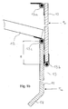
- Fig. 1a shows a 2: 1 suspended in a traction drive pulley elevator with its main components
- the elevator is shown as such only schematically and is used in the representation chosen here only as an example - the invention can equally be used in quite different types of elevators including hydraulic lifts.
- the elevator consists of an elevator car 1, which runs along the guide rails, not shown, the shaft 2 along.
- a traction sheave drive 3 is provided between the area traveled by the cabin or its extensions upward and the shaft wall, which is here, purely by way of example, designed as a drive with so-called double wrap.
- the support cable 4 runs on one side to the cabin, is by means of pulleys 5 passed under the cabin 1 and runs on the other side back up into the shaft head where the support cable is fixed (not shown here).
- the support cable 4 runs from the drive to the counterweight 6, which may possibly also be suspended in a bottle (not shown here).
- FIG. 1a The illustration selected from Fig. 1a shows the situation that the car has kept unscheduled in the shaft, for example due to a power failure or damage to the traction sheave drive.
- the car 1 is therefore only partially in front of the shaft door opening 6.
- the passengers are released from the car by the car doors are opened manually.
- the passengers sat in such a situation, at least if a greater height difference to the floor floor is overcome, i. d. R. on the threshold of the car door and can then slide down along the arrow P with his feet to the floor floor 7.
- the safety system which will be explained in more detail below, consists of a car apron 9 with two largely rigid apron elements 10 and 11 and the movement of these apron elements guiding elements in the form of a linkage comprising two articulated levers 12.
- the two skirt elements 10 and 11 are here in their so-called protective position, d. H. they depend vertically oriented, so largely vertically extending from the bottom of the car compartment down (with minor deviations from the vertical are harmless, a fully vertical orientation is desired).
- the two skirt elements 10, 11 are locked in their protection position - the skirt elements can not be moved relative to each other or jointly in the shaft direction by forces acting from the shaft door opening in the baywise and substantially horizontal directions on one or both of the skirt elements 10, 11 be panned. Being remarkable is that there is a self-locking lock - the attack of said forces causes the skirt elements are held even more firmly in their protective position. In order to bring the skirt elements out of their protective position, the larger the said forces acting in the horizontal-bayward direction, the greater are the greater the forces required.
- FIG. 1b shows a detail of the safety system shown in FIG. 1a, namely the area in which the two skirt elements 10 and 11 are hinged to one another and the second skirt element 11 is articulated to the articulated lever 12.
- first apron element 10 Shown here is a first apron element 10, which is articulated by means of the hinge 13a in the region near the threshold of the elevator car pivotally mounted on the elevator car.
- the first skirt element 10 is largely rigid in itself.
- this apron element is formed from a full-surface sheet, although admittedly allows certain twists, but does not yield significantly, so in itself is largely rigid.
- this apron element can also be formed, for example, by a circumferential, substantially rigid apron element frame, which is planked or tightly covered with a suitable material, for example a plastic plate, a Kevlar fabric or thick nylon fabric or a glass fiber fabric.
- skirt element has no larger openings which are accessible from the shaft door opening, when the skirt element is in the protective position. Any larger openings, ie openings that allow penetration of whole body parts, represent a source of potential injury.
- first skirt element 10 the same design options are open as for the first skirt element 10.
- both skirt elements are of similar construction.
- the skirt member 11 is hinged to the first skirt member via a hinge 13b.
- the hinge 13b is there (relative to the protective position) mounted in the vicinity of the lower horizontally oriented end edge of the first skirt member 10.
- the hinge is attached to the further skirt element 11. This, however, at some distance from its (seen in protective position) horizontally aligned upper end edge.
- the articulated lever 12 is articulated via a further hinge 13c, which not only functions as a guide means that controls the folding and unfolding, but also as in its length (between its articulation points under the car and the skirt element 11) variable locking means.
- lever arm H As a result of the just described type of articulation of the articulated lever, the articulation point of the articulated lever 12, based on the axis of the hinge 13b, a lever arm H.
- the length of this lever arm H is to be dimensioned depending on the circumstances of the case.
- the two skirt elements 10 and 11 when in protective position as in this case, essentially form a flat surface - in which the two skirt elements lie parallel to each other in two directly adjacent planes (apart from the deflector slope 14 at the lower end of the lower protective element 11), so that they form substantially a total area, at which even when the elevator is still moving, nothing can get caught, and the an approximately equal gap distance between the apron surface and the top of each floor floor 7 ensures.
- Fig. 1c shows (schematically) the safety system just discussed in its rest position. Preferably, this rest position is always taken when scheduled operation expires.
- the safety device comprises an electric holding magnet 16 mounted on an unspecified carrier. This acts (with respect to the protective position) on the lower portion 12b of the articulated lever 12 and holds it in an approximately horizontal, folded position. It is not necessary (and preferably even waived) that the security system is folded completely flat under the car floor. Rather, the security system can and should not be folded completely flat even when folded, but by a certain amount "Apply" in the vertical direction.
- FIG. 1i shows a section of the articulated lever 12 in the region of the articulation 12c between the upper articulated lever part 12a and the lower articulated lever part 12b.
- the lower articulated lever part 12b is in this case with a stop lug Equipped 12d, which limits the Verschwenkweg the two articulated levers 12a and 12b to each other. It is the case that the articulated lever can only continue to buckle from the position shown here in such a way that the articulation point 12c moves upwards in the direction of the arrow. From this position, it is not possible to bend the articulated lever so that the articulated axle 12c moves downwards, in the opposite direction of the arrow.
- the articulated lever 12 is designed so that the longitudinal axis 12f of the articulated lever part 12b deviates by a few degrees from the longitudinal axis 12e of the upper articulated lever part 12a. In this way, the articulated lever is self-locking in the sense that even when high forces occur in the axial direction of the axle 12c can not be made to emigrate upward in the direction of the arrow.
- the safety device can be unlocked, for example, by a small, possibly closable hole (closable by plugs or the like) is provided in the upper skirt member 10 at a suitable location by the means of a hook rod or other suitable tool from the floor side in the direction of the arrow the buckling lever 12 can be pulled to cause it to buckling. Then both apron elements together with the associated guide means can be brought back into the rest position - manually or with a corresponding device.
- a suitable actuator pneumatic cylinder, motorized threaded rod, linear motor or the like
- a suitable actuator pneumatic cylinder, motorized threaded rod, linear motor or the like
- Figs. 1g and 1h again show the construction of the first embodiment just discussed in three-dimensional view.
- Figs. 2a to 2d show a second embodiment of the invention.
- the two skirt elements 10 and 11 can be hinged to each other in the same way as that shown in FIG. 1b for the previous embodiment.
- Changed here are only the guiding and locking means, which are designed in the form of a pivot lever 120, which consists of two sections, namely its upper portion 120 b and its lower portion 120 a.
- This pivot lever 120 is articulated with its lower portion 120a in the same way as before, hinged to the lower skirt member 11.
- the upper portion 120 b of the pivot lever 120 is guided horizontally displaceable in linear guides 16.
- an actuating member in the form of a linear drive 121 is articulated at the lower portion 120a of the pivoting lever 120 in the second exemplary embodiment shown concretely here.
- This linear drive 121 makes it possible to bring the skirt elements 10, 11 at any desired time from its rest position to its protective position, and vice versa.
- This variant is therefore particularly suitable for elevator systems in which a premature opening of the shaft doors should be made, and therefore the apron must remain in protective position even during regular operation until the car anograph the lowest stop where the apron must be retracted for reasons of space .
- the construction is, as is preferred, designed so that the linear drive, for example because its piston rod is retracted against the force of a spring, even in a power failure, ie when no supply voltage is available, the skirt elements 10, 11 automatically in its protective position bring where they lock. A locking takes place because the lower portion 120a of the pivot lever 120 articulated on both sides is. Due to this, it can not transmit compressive forces in the horizontal direction.
- this portion 120a of the pivot lever 120 tries to go even further in a vertical orientation, if it is loaded from the outside with forces acting in the horizontal direction.
- the linear guides 16 so to speak, the lower and the upper section of the pivot lever "wedge" and thus lock automatically or ideally self-locking.
- the linear guides are designed so that no automatic or self-locking locking takes place, means should be used to ensure locking externally. For example, it makes sense to use the linear drive for locking and / or provide further means (such as spring-biased locking pins which engage corresponding recesses of the pivot lever 120), which prevent the upper portion 120b of the pivot lever continue to move in the linear guides 16 and can dodge.
- Fig. 2d is shown how the blockade can be canceled again if you want to go to the regular operating state.
- a small, possibly closed by a stopper opening provided, can be inserted through the means of a suitable push rod, the upper part 120a of the pivot lever 120 back into its horizontal linear guides ,
- this embodiment can also be modified to the effect that the linear drive 121 is dispensed with.
- locking means are provided which hold the running in the linear guides end 120 b of the pivot lever 120, as long as the skirt elements are to assume their rest position.
- the blockade is released.
- the two skirt elements 10 and 11 fall under their own weight down, unfold and pull the portion 120b of the pivot lever out of its linear guides, so that the skirt elements under the influence of their own weight over the self in Fig. 2b (for the variant with linear drive) shown intermediate position 2c and can lock there, preferably automatically or self-locking, as described above.
- FIGS. 3a to 3d show a third exemplary embodiment. This corresponds, at least as far as the kinematics of the two skirt elements 10 and 11, largely the first embodiment, unless otherwise described below. Only the guiding and locking means are designed differently here. Instead of a buckling lever 12, an actuating member 1200 is used here, which is articulated at the appropriate place as the articulated lever 12 at the lower apron element articulated. At the same time, the two skirt elements 10 and 11 are elastically biased against each other at this point by means of a suitable torsion spring 1200a such that the two skirt elements automatically fold when the piston rod of the linear drive retracts (FIGS. 3c, 3d).
- This actuating element 1200 is preferably a linear drive, ie a cylinder driven by an electric motor or by fluid pressure with a retractable and extendable piston or threaded rod (in the broadest sense), which ensures a corresponding actuation of the skirt elements.
- a mechanism is provided which can extend the linear drive even in case of power failure such that it brings the skirt elements in the protective position and keeps locked there.
- the linear drive for example, works against a spring accumulator, which can extend the linear drive on collapse of the supply voltage to the protection position.
- a device is additionally provided which locks the linear drive, if no supply voltage is available, in that extended position corresponding to the protective position. This can be z. B.
- FIGS. 4a to 4c show a further example which largely corresponds to the above-described second exemplary embodiment.
- the lower end of the lower skirt element 11 (relative to the protective position) is provided with a roller which guides the lower end of this skirt element during unfolding, and especially when the protective position is reached, with respect to the shaft wall.
- the lower end of the apron element 11 wedged against the shaft wall during deployment, so not pivoted into its final protective position and no Self-locking occurs.
- such a role is especially advantageous if the car apron, z. B. due to "leading shaft door opening", should remain permanently unfolded.
Abstract
Description
Die Erfindung betrifft ein Sicherheitssystem für einen Aufzug mit einer Fahrkorbschürze gemäß dem Oberbegriff des Anspruchs 1.The invention relates to a safety system for a lift with a car apron according to the preamble of
Es ist seit langem Stand der Technik, unterhalb der Fahrkorbtüröffnung von Aufzügen Schürzen anzubringen, die sich abwärts von der Fahrkorbtürschwelle in vertikaler Richtung erstrecken.It has long been the state of the art to install under the car door opening of elevators aprons extending downwards from the car door sill in the vertical direction.
Derartige Sicherheitssysteme mit einer Fahrkorbschürze bieten Schutz, falls Fahrgäste aus einem Fahrkorb befreit werden müssen, der im Bereich einer Stockwerksöffnung, in Entfernung von der an und für sich vorgesehenen Halteposition hängen geblieben ist. In einem solchen Fall tut sich ein mehr oder minder großer Spalt zwischen der Unterkante des Fahrkorbbodens und der Oberseite der Stockwerksdecke auf. Die zu evakuierenden Personen werden sich im Regelfall auf den Fahrkorbboden setzen und sich dann mit den Beinen voraus aus dem Fahrkorb ablassen, bis sie auf der Stockwerksdecke zum Stehen kommen. Hier besteht nun die Gefahr, dass diese Personen in Rücklage kommen und durch den Spalt zwischen der Unterseite des Fahrkorbs und der Oberseite der Stockwerksdecke in den Schacht abstürzen.Such safety systems with a car apron provide protection in case passengers have to be released from a car stuck in the area of a floor opening, at a distance from the inherent stopping position. In such a case, a more or less large gap between the lower edge of the car floor and the top of the floor ceiling opens up. The people to be evacuated will usually sit on the car floor and then let their legs out of the car until they come to a stop on the floor. There is now the danger that these people come in reserve and crash through the gap between the bottom of the car and the top of the floor ceiling in the shaft.
Diese Gefahr bannt ein Sicherheitssystem der hier in Rede stehenden Art, indem es mit seiner Fahrkorbschürze den Spalt zwischen dem Fahrkorbboden und der Stockwerksdecke verschließt.This danger eliminates a safety system of the type in question by closing the gap between the car floor and the floor ceiling with its car apron.
Um sicher wirken zu können, muss die Fahrkorbschürze eines solchen Sicherheitssystems eine beachtliche Länge in vertikaler Richtung haben. Die einschlägigen Normen fordern im Regelfall eine Länge von nicht weniger als 750 mm.To be sure, the car apron of such a safety system must have a considerable length in the vertical direction. The relevant standards usually require a length of not less than 750 mm.
Vielfach werden im Stand der Technik starre Fahrkorbschürzen verwendet. Dies bedeutet dann allerdings, dass auch im Schachtgrund hinreichend Platz vorhanden sein muss, damit die Fahrkorbschürze auch dann nicht auf dem Schachtboden anstößt, wenn der Fahrkorb die unterste Haltestelle anfährt.In many cases rigid car skirts are used in the prior art. However, this then means that sufficient space must also be available in the shaft base, so that the car apron does not hit the shaft floor even when the car approaches the lowest stop.
Es gibt zahlreiche Fälle (insbesondere bei Altbausanierungen, im Rahmen derer mit vorgefundenen Schächten zurechtzukommen ist), in denen im unteren Bereich des Schachtgrundes nicht genügend Platz zur Verfügung steht, um eine starre Fahrkorbschürze zuzulassen. Im Stand der Technik sind daher eine ganze Reihe von klappbaren bzw. ausziehbaren oder sogar aushängbaren Fahrkorbschürzen bekannt geworden - also Fahrkorbschürzen, die wahlweise in eine sogenannte Schutzposition gebracht werden können, in der sie vom Fahrkorb in Richtung Schachtgrund ragen und, wie geschildert, Schutz gegen Unfälle durch Einklemmen bzw. Absturz in den Schacht bieten, bzw. in eine Ruheposition, in der sie soweit eingezogen oder beiseite geklappt sind, dass kein Aufsetzen auf dem Schachtgrund zu befürchten ist.There are numerous cases (especially in old building renovations, in the context of which it can cope with found manholes), in which at the bottom of the shaft bottom there is not enough space to allow a rigid car apron. In the prior art, therefore, a whole series of hinged or retractable or even retractable car aprons have become known - so car aprons, which can be optionally placed in a so-called protective position in which they protrude from the car toward the shaft base and, as described, protection against Accidents by trapping or crashing into the shaft provide, or in a rest position in which they are drafted or pulled aside so far that no placement on the shaft base is to be feared.
So schlägt beispielsweise die
Die
Diese Konstruktion weist zwei Nachteile auf. Zum einen ist die Schürze in ihrer Schutzposition nicht blockiert. Das heißt, es kann nicht ausgeschlossen werden, dass die Schürze durch Einwirkung stärkerer Kräfte, die in etwa horizontal in schachteinwärtiger Richtung wirken, beiseite gedrückt wird. Etwa in Situationen, in denen ein Fahrgast versucht, sich aus einem sehr hoch über der Stockwerksdecke stecken gebliebenen Fahrkorb auf die Stockwerksdecke herabzulassen, dabei das Gleichgewicht verliert und rückwärts in schachteinwärtiger Richtung gegen die Schürze fällt.This construction has two disadvantages. Firstly, the apron is not blocked in its protective position. That is, it can not be ruled out that the skirt is pushed aside by the action of stronger forces acting approximately horizontally in the shaft-wise direction. For example, in situations where a passenger tries to descend from a car stuck high above the floor ceiling onto the floor, thereby losing his balance and falling backwards against the apron in the direction of the shaft.
Zum anderen ist bei dieser Konstruktion nachteilig, dass die Schürze in ihrem eingeklappten Zustand eine relativ große Fläche unter dem Fahrkorb "blockiert". Dies insoweit, als in diesem Bereich keine anderen Funktionselemente unter dem Fahrkorbboden angebracht werden können, wie etwa Umlenkrollen oder Anschläge, die mit auf dem Schachtgrund angebrachten Puffern zusammenwirken bzw., im Falle selbstfahrender Fahrkörbe, der fahrkorbfeste Antrieb. Dies spielt insbesondere bei Aufzügen mit einer relativ kleinen Kabine, an der auch unter dem Kabinenboden nur relativ wenig Fläche zur Verfügung steht, eine Rolle.On the other hand is disadvantageous in this construction that the skirt in its folded state "blocks" a relatively large area under the car. This insofar as in this area no other functional elements can be mounted under the car floor, such as pulleys or stops, which cooperate with mounted on the shaft base buffers or, in the case of self-propelled cars, the car-proof drive. This plays a role in particular in elevators with a relatively small cabin, at which even under the cabin floor only relatively little area is available.
Aus der
Diese Konstruktion hat verschiedene Nachteile. Zum einen führt die einen Durchgriff ermöglichende Öffnung dieser Konstruktion zur Gefährdung.This construction has several disadvantages. On the one hand leads to a penetration permitting opening of this construction to the dangers.
Vor allem ist diese Konstruktion jedoch deswegen nicht ganz ungefährlich, weil sie nicht verriegelt und insbesondere nicht selbsthemmend ist. Das ist entscheidend. Denn es ist wiederum so, dass eine Person, die beim Notausstieg aus dem Fahrkorb mit den Füßen auf der Stockwerksdecke aufgekommen ist und in diesem Augenblick das Gleichgewicht verliert und unglücklich nach hinten gegen die Fahrkorbschürze fällt, die Fahrkorbschürze um ein nicht unerhebliches Maß beiseite drücken kann.
Zudem beansprucht auch diese Konstruktion, obgleich die die eigentliche Fahrkorbschürze bildenden Platten faltbar sind, erheblichen Freiraum unter dem Fahrkorbboden. Dies deshalb, weil die schachteinwärts gerichtete Verbindungsstange zwischen dem Viergelenk und der untersten Platte der Fahrkorbschürze annähernd genauso lang ist, wie die beiden Platten der Fahrkorbschürze in ihrer auseinandergeklappten Stellung. Die Konstruktion benötigt daher deutlich mehr Platz unter dem Fahrkorbboden, als es die beiden zusammengefalteten Platten per se erfordern.Above all, however, this construction is not completely harmless because it is not locked and in particular is not self-locking. That's crucial. Because it is again so that a person who has emerged from the car with the feet on the floor during the emergency exit and at this moment loses its balance and falls unhappy back against the car apron, the car apron can push aside a considerable amount aside ,
In addition, this construction, although the actual car apron plates forming folds claimed considerable space under the car floor. This is because the inboard tie bar between the four-bar link and the bottom plate of the car apron is approximately as long as the two panels of the car apron are in their unfolded position Position. Therefore, the construction requires significantly more space under the car floor, as required by the two folded plates per se.
Der Erfindung liegt die Aufgabe zu Grunde, ein Sicherheitssystem mit einer beweglichen Fahrkorbschürze zu schaffen, die in Schutzposition verbesserten Schutz bietet und die Möglichkeit eröffnet, für die Ruheposition nur weniger Fläche unter dem Fahrkorb freihalten zu müssen.The invention is based on the object to provide a safety system with a movable car apron, which offers improved protection in protection position and opens the possibility to have to keep free for the rest position only less area under the car.
Diese Aufgabe wird erfindungsgemäß dadurch gelöst, dass das Sicherheitssystem Mittel aufweist, mittels derer die faltbaren Schürzenelemente in ihrer Schutzposition derart verriegelbar sind, dass sie durch von außen und in schachteinwärtiger, im wesentlichen horizontaler Richtung an einem oder mehreren Schürzenelementen angreifende Kräfte weder relativ zueinander bewegt, noch gemeinsam in schachteinwärtiger Richtung geschwenkt werden können. Kleinere, z. B. gewisse durch Elastizität bedingte Relativbewegungen zueinander oder insgesamt schachteinwärts, sind unkritisch und daher zuzulassen. Idealerweise sind die Verriegelungsmittel selbsthemmend ausgelegt, d. h. eine in Öffnungsrichtung angreifende Kraft sperrt das Verriegelungsmittel gegen Öffnen, so dass die in Öffnungsrichtung wirkende Kraft beliebig groß werden kann, ohne dass zu befürchten ist, dass die Verriegelung nachgibt (solange keine Bauteilzerstörung auftritt).This object is achieved according to the invention in that the safety system has means by means of which the foldable skirt elements can be locked in their protective position in such a way that they are not moved relative to one another by forces acting on one or more skirt elements from the outside and in the bay-like, substantially horizontal direction. can still be pivoted together in the bay direction. Smaller, z. B. certain elasticity relative movements to each other or in total shaft inward, are uncritical and therefore allow. Ideally, the locking means are self-locking, d. H. a force acting in the opening direction locks the locking means against opening, so that the force acting in the opening direction can be arbitrarily large without it being feared that the locking will yield (as long as no component destruction occurs).
Auf diese Art und Weise wird auch bei einer Fahrkorbschürze aus faltbaren und damit platzsparenden Schürzenelementen eine hohe Sicherheit erreicht.In this way, a high security is achieved even with a car apron of foldable and thus space-saving apron elements.
Eine vorteilhafte Weiterbildung sieht vor, dass die Faltbewegungen der die Schürzenelemente lenkenden Führungsmittel so gestaltet sind, und so an einem der Schürzenelemente angreifen, dass sie in Schutzposition gleichzeitig als Verriegelungsmittel wirken, indem sie die Schürzenelemente in ihrer Schutzposition gegeneinander und gleichzeitig gegen ein gemeinsames Verschwenken in schachteinwärtiger Richtung verriegeln.An advantageous development provides that the folding movements of the apron elements guiding means are designed so attack on one of the skirt elements that they simultaneously act in the protective position as a locking means by the skirt elements in their protective position against each other and at the same time against a common pivoting in lock in the inward direction.
Eine derartige Gestaltung führt zu einer wesentlichen Vereinfachung. Es bedarf keiner zusätzlichen Verriegelungsmittel mehr.Such a design leads to a substantial simplification. It requires no additional locking means more.
Eine vorteilhafte Weiterbildung sieht vor, dass die Achse, um die herum die Führungs- bzw. Verriegelungsmittel schwenkbar an einem der Schürzenelemente angeordnet sind, in vertikaler Richtung gesehen, zwischen der Achse liegt, um die herum das fahrkorbnächste Schürzenelement schwenkbar am Fahrkorb angelenkt ist, und der Achse, die die Schürzenelemente relativ zueinander verbindet. Eine derartige Achsenlage gestattet auf besonders einfache Art und Weise eine wirksame, weil vorzugsweise selbsthemmende Verriegelung der Schürzenelemente.An advantageous development provides that the axis around which the guide or locking means are pivotally mounted on one of the skirt elements, seen in the vertical direction, between the axis is about which the car next apron element pivotally hinged to the car, and the axis that connects the skirt elements relative to each other. Such an axial position allows in a particularly simple manner an effective, because preferably self-locking locking the skirt elements.
Bevorzugterweise sind die Schürzenelemente so aneinander angelenkt, dass an einem Schürzenelement die gemeinsame Anlenkachse von dessen nächstliegender Horizontalkante entfernt angeordnet ist, so dass der Abschnitt dieses Schürzenelements, der sich zwischen der gemeinsamen Anlenkachse und der Horizontalkante erstreckt, in Bezug auf die gemeinsame Anlenkachse einen Hebelarm bildet, an dem die Führungs- bzw. Verriegelungsmittel angreifen. Dieser Hebelarm gestattet eine selbsthemmende Blockade der beiden Schürzenelemente.Preferably, the skirt elements are hinged to each other so that on a skirt element, the common pivot axis is disposed away from its nearest horizontal edge, so that the portion of this apron element which extends between the common pivot axis and the horizontal edge, forms a lever arm with respect to the common pivot axis on which the guiding or locking means engage. This lever arm allows a self-locking blockage of the two skirt elements.
Bevorzugterweise umfassen die Führungs- und/oder Verriegelungsmittel mindestens eine Zug- oder Druckstange, die in sich faltbar ist. Dies verkleinert den Platzbedarf unter dem Fahrkorb in Ruheposition, da dann nicht nur die Schürze, sondern auch die für die Konstruktion eingesetzten Zug- bzw. Druckstangen nur wenig Platz einnehmen. Aus gleichem Grunde sieht eine weitere bevorzugte Ausführungsform vor, dass die Führungs- und/oder Verriegelungsmittel mindestens ein teleskopierbares Betätigungsorgan umfassen.Preferably, the guiding and / or locking means comprise at least one pull or push rod, which is foldable in itself. This reduces the space requirement under the car in rest position, since then occupy not only the apron, but also the draft or push rods used for the construction of little space. For the same reason, a further preferred embodiment provides that the guiding and / or locking means comprise at least one telescopic actuating member.
Im Rahmen einer weiteren bevorzugten Ausführungsform ist vorgesehen, dass sich die Schürzenelemente in ihrer Schutzposition in einer Ebene oder weitgehend parallel zueinander entlang zweier unmittelbar benachbarter Ebenen erstrecken, so dass sie eine im wesentlichen ebene Gesamtfläche bilden. Eine solche Gestaltung macht es möglich, den Spalt zwischen der Fahrkorbschürze und der Oberkante der jeweiligen Stockwerksdecke weitgehend konstant klein zu halten. Die Gefahr eines Einklemmens wird noch geringer als bei Verwendung einer Schürze mit einem "Knick", d. h. einer Schürze, deren Schürzenelemente mehr als nur unwesentlich winkelig zueinander angeordnet sind.In the context of a further preferred embodiment, it is provided that the skirt elements extend in their protective position in a plane or substantially parallel to one another along two directly adjacent planes, so that they form a substantially flat overall surface. Such a design makes it possible to control the gap between the car apron and the upper edge of the respective one Floor ceiling to keep largely constant small. The risk of pinching is even lower than when using a skirt with a "kink", ie an apron, the skirt elements are arranged more than slightly angularly to each other.
Eine weitere bevorzugte Ausgestaltung sieht vor, dass die Schürzenelemente in ihrer Ruheposition von einem weiteren Verriegelungsmittel derart unter dem Fahrkorbboden gehalten werden, dass sie selbsttätig in die Schutzposition schwenken und dort verriegeln, wenn die Verriegelung des besagten weiteren Verriegelungsmittels deaktiviert wird. Eine solche Ausgestaltung gewährleistet, dass auch bei plötzlichen Stromausfällen, die die Notwendigkeit eines späteren Notausstiegs der Fahrgäste zur Folge haben, die Schürzenelemente zuverlässig in ihre Schutzposition gebracht werden.A further preferred embodiment provides that the skirt elements are held in its rest position by another locking means under the car floor so that they automatically pivot in the protective position and lock there when the lock of said further locking means is deactivated. Such an embodiment ensures that even with sudden power outages, which have the consequence of a subsequent emergency exit of the passengers result, the apron elements are reliably placed in their protective position.
Bevorzugt wird eine Überwachungseinrichtung vorgesehen, mittels der detektiert werden kann, ob die Schürzenelemente nach ihrem Einsatz ordnungsgemäß ihre Ruheposition einnehmen und die Fahrt erst freigibt, wenn das der Fall ist, so wird ein Aufsetzten verhindert.Preferably, a monitoring device is provided, by means of which it can be detected whether the apron elements properly assume their rest position after their use and release the ride only when that is the case, so putting on is prevented.
Weitere Vorteile, Merkmale und Einzelheiten der Erfindung ergeben sich aus der nachfolgenden Beschreibung bevorzugter Ausführungsbeispiele an Hand der Zeichnung. Darin zeigen:
- Fig. 1a:
- Ein erstes Ausführungsbeispiel der Erfindung, montiert an einem in einem Schacht laufenden Treibscheibenaufzug, wobei die Schürzenelemente in Schutzposition ausgefahren sind;
- Fig. 1b:
- einen vergrößerten Ausschnitt des von Fig. 1a offenbarten Ausführungsbeispiels, und zwar im Bereich des gelenkigen Stoßes zwischen den beiden
Schürzenelementen 10und 11; - Fig. 1c bis 1f:
- das erste Ausführungsbeispiel der Erfindung in verschiedenen Stadien des Auseinander- und Zusammenfaltens;
- Fig. 1g und 1h:
- eine perspektivische Ansicht dieses ersten Ausführungsbeispiels;
- Fig. 1i:
- einen vergrößerten Ausschnitt des von dem ersten Ausführungsbeispiel verwendeten Knickhebels;
- Fig. 2a bis 2d:
- ein zweites Ausführungsbeispiel in verschiedenen Positionen des Zusammen- und Auseinanderfaltens;
- Fig. 3a bis 3d:
- ein drittes Ausführungsbeispiel in verschiedenen Positionen des Zusammen- und Auseinanderfaltens;
- Fig. 3e und 3f:
- eine perspektivische Darstellung des dritten Ausführungsbeispiels schräg von unten gesehen, und
- Fig. 4a bis 4c:
- eine mit einer zusätzlichen Führungsrolle am Schürzenende versehene Variante des zweiten Ausführungsbeispiels.
- Fig. 1a:
- A first embodiment of the invention mounted on a traction sheave elevator running in a shaft, wherein the skirt elements are extended in the protective position;
- Fig. 1b:
- an enlarged section of the embodiment disclosed in Figure 1a, in the region of the articulated joint between the two
skirt elements - 1c to 1f:
- the first embodiment of the invention in various stages of unfolding and folding;
- Fig. 1g and 1h:
- a perspective view of this first embodiment;
- Fig. 1i:
- an enlarged section of the buckle lever used by the first embodiment;
- 2a to 2d:
- a second embodiment in different positions of folding and unfolding;
- 3a to 3d:
- a third embodiment in various positions of folding and unfolding;
- 3e and 3f:
- a perspective view of the third embodiment viewed obliquely from below, and
- 4a to 4c:
- a provided with an additional guide role at the skirt end variant of the second embodiment.
Die Fig. 1a zeigt einen 2 : 1 in Flasche aufgehängten Treibscheibenaufzug mit seinen wichtigsten Bauteilen, wobei der Aufzug als solcher lediglich schematisch dargestellt ist und in der hier gewählten Darstellung lediglich als Beispiel dient - die Erfindung kann gleichermaßen auch in ganz andere Typen von Aufzügen eingesetzt werden, einschließlich Hydraulikaufzügen.Fig. 1a shows a 2: 1 suspended in a traction drive pulley elevator with its main components, the elevator is shown as such only schematically and is used in the representation chosen here only as an example - the invention can equally be used in quite different types of elevators including hydraulic lifts.
Der Aufzug besteht aus einer Aufzugskabine 1, die an hier nicht dargestellten Führungsschienen den Schacht 2 entlang läuft. Im Schachtkopf ist zwischen dem von der Kabine befahrenen Bereich bzw. dessen Verlängerungen nach oben und der Schachtwand ein Treibscheibenantrieb 3 vorgesehen, der hier, rein exemplarisch, als Antrieb mit sogenannter doppelter Umschlingung ausgeführt ist. Von dem Antrieb aus läuft das Tragseil 4 auf der einen Seite zur Kabine, wird mittels Umlenkrollen 5 unter der Kabine 1 hindurch geführt und läuft an der anderen Seite wieder nach oben in den Schachtkopf, wo das Tragseil festgelegt ist (hier nicht gezeigt). Auf der anderen Seite läuft das Tragseil 4 von dem Antrieb aus zum Gegengewicht 6, das ggf. ebenfalls in Flasche aufgehängt sein kann (hier nicht gezeigt).The elevator consists of an
Die von Fig. 1a gewählte Darstellung zeigt die Situation, dass der Fahrkorb außerplanmäßig im Schacht gehalten hat, etwa wegen eines Stromausfalls oder eines Schadens am Treibscheibenantrieb. Der Fahrkorb 1 befindet sich daher nur teilweise vor der Schachttüröffnung 6. Die Fahrgäste werden aus dem Fahrkorb befreit, indem die Fahrkorbtüren manuell geöffnet werden. Die Fahrgäste setzten sich in einer solchen Situation, jedenfalls wenn ein größerer Höhenunterschied zum Stockwerksboden zu überwinden ist, i. d. R. auf die Schwelle der Fahrkorbtür und lassen sich dann entlang des Pfeils P mit den Füßen voran zum Stockwerksboden 7 hinabgleiten.The illustration selected from Fig. 1a shows the situation that the car has kept unscheduled in the shaft, for example due to a power failure or damage to the traction sheave drive. The
Der an und für sich die Gefahr eines Absturzes in den Schacht bergende Spalt zwischen dem Stockwerksboden 7 und der Kabinentürschwelle 8 wird durch das Sicherheitssystem verschlossen. Das Sicherheitssystem, das gleich noch näher erläutert wird, besteht aus einer Fahrkorbschürze 9 mit zwei weitgehend in sich starren Schürzenelementen 10 und 11 sowie die Bewegung dieser Schürzenelemente lenkenden Führungselementen in Form eines Gestänges, das zwei Knickhebel 12 umfasst. Die beiden Schürzenelemente 10 und 11 befinden sich hier in ihrer sogenannten Schutzposition, d. h. sie hängen vertikal orientiert, also weitgehend vertikal verlaufend vom Bodenbereich des Fahrkorbes nach unten (wobei geringe Abweichungen von der Vertikalen unschädlich sind, eine vollständig vertikale Ausrichtung jedoch erwünscht ist).The inherent in the risk of falling into the shaft gap between the
Die beiden Schürzenelemente 10, 11 sind in ihrer Schutzposition verriegelt - die Schürzenelemente können durch Kräfte, die von der Schachttüröffnung her in schachteinwärtiger und im wesentlichen horizontaler Richtung an einem oder beiden der Schürzenelemente 10, 11 angreifen, weder relativ zueinander bewegt noch gemeinsam in schachteinwärtiger Richtung geschwenkt werden. Wobei bemerkenswert ist, dass hier eine selbsthemmende Verriegelung vorliegt - das Angreifen der besagten Kräfte führt dazu, dass die Schürzenelemente noch fester in ihrer Schutzposition gehalten werden. Um die Schürzenelemente aus ihrer Schutzposition zu bringen, sind umso größere anderweitige Kräfte aufzubringen, je größer die besagten in horizontal-schachteinwärtiger Richtung angreifenden Kräfte sind.The two
Warum dem so ist, wird an Hand der Fig. 1b klar. Die Fig. 1b gibt einen Ausschnitt des von Fig. 1a gezeigten Sicherheitssystems wieder, und zwar des Bereiches, in dem die beiden Schürzenelemente 10 und 11 aneinander angelenkt sind und das zweite Schürzenelement 11 an den Knickhebel 12 angelenkt ist.Why this is so, becomes clear with reference to FIG. 1b. FIG. 1b shows a detail of the safety system shown in FIG. 1a, namely the area in which the two
Gezeigt ist hier ein erstes Schürzenelement 10, das mittels des Scharniers 13a im Bereich nahe der Schwelle des Aufzugsfahrkorbs schwenkbar am Aufzugsfahrkorb angelenkt ist. Das erste Schürzenelement 10 ist in sich weitestgehend starr. Vorzugsweise ist dieses Schürzenelement aus einem vollflächigen Blech gebildet, das zwar gewisse Verwindungen zulässt, aber nicht wesentlich nachgibt, also in sich weitgehend starr ist. Alternativ kann dieses Schürzenelement aber auch beispielsweise durch einen umlaufenden, in sich weitgehend starren Schürzenelementrahmen gebildet werden, der mit einem geeigneten Material beplankt oder straff bespannt ist, etwa einer Kunststoffplatte, einem Kevlargewebe oder dickem Nylonstoff bzw. einem Glasfasergewebe. Ganz gleich, von welchen dieser Möglichkeiten dieses Schürzenelement Gebrauch macht, ist es in jedem Fall besonders bevorzugt, dass das Schürzenelement keine größeren Öffnungen aufweist, die von der Schachttüröffnung her zugänglich sind, wenn sich das Schürzenelement in Schutzposition befindet. Jegliche größere Öffnungen, also Öffnungen, die ein Eindringen von ganzen Körperteilen ermöglichen, stellen eine Quelle potentieller Verletzungen dar. Für das weitere Schürzenelement 11 stehen die gleichen Gestaltungsoptionen offen, wie für das erste Schürzenelement 10. Vorzugsweise sind beide Schürzenelemente gleichartig aufgebaut.Shown here is a
Das Schürzenelement 11 ist über ein Scharnier 13b gelenkig am ersten Schürzenelement angebracht. Das Scharnier 13b ist dabei (bezogen auf die Schutzposition) im Nahbereich der unteren horizontal ausgerichteten Endkante des ersten Schürzenelements 10 angebracht. Gleichzeitig ist das Scharnier an dem weiteren Schürzenelement 11 angebracht. Dies allerdings mit einigem Abstand von dessen (gesehen in Schutzposition) horizontal ausgerichteter oberer Endkante. Im Nahbereich der oberen horizontal ausgerichteten Endkante des weiteren Schürzenelements 11 ist über ein weiteres Scharnier 13c der Knickhebel 12 gelenkig angelenkt, der hier nicht nur als Führungsmittel, das das Zusammen- und Entfalten steuert, fungiert, sondern auch als in seiner Länge (zwischen seinen Anlenkpunkten unter dem Fahrkorb und dem Schürzenelement 11) veränderliches Verriegelungsmittel. In Folge der soeben geschilderten Art der Anlenkung des Knickhebels besitzt die Anlenkstelle des Knickhebels 12, bezogen auf die Achse des Scharniers 13b, einen Hebelarm H. Die Länge dieses Hebelarms H ist abhängig von den Gegebenheiten des Einzelfalls zu dimensionieren.The
Zu dieser Selbsthemmung ist kurz folgendes festzuhalten:To this self-inhibition is briefly stated:
Wirkt am oberen Schürzenelement 10 beispielsweise eine schachteinwärts gerichtete, im wesentlichen horizontale Kraft Fh1 in schachteinwärtiger Richtung, so versucht diese Kraft, das obere Schürzenelement 10 im Uhrzeigersinn schachteinwärts zu verdrehen. Das obere Schürzenelement 10, das ja über das Scharnier 13b am unteren Schürzenelement 11 angelenkt ist, wird an einer solchen Bewegung gehindert, da es gegen das untere Schürzenelement 11 und damit mittelbar gegen den Knickhebel 12 anläuft. Dieser vermag sich, da verriegelt, nicht zu verkürzen. Dadurch werden die beiden Schürzenelemente gegeneinander verriegelt, und zwar auch insoweit, als sie nicht miteinander schachteinwärts geschwenkt werden können.For example, on the
Eine ähnliche Situation ergibt sich, wenn am unteren Schürzenelement 11 eine im wesentlichen horizontal in schachteinwärtiger Richtung angreifende Kraft Fh2 auftritt. Diese Kraft versucht das untere Schutzelement 11 im Uhrzeigersinn schachteinwärts zu drehen, um die Achse des Scharniers 13c. An dieser Bewegung wird das untere Schürzenelement 11 durch das mit ihm über das Scharnier 13b verbundene obere Schürzenelement 10 gehindert. Denn das obere Schürzenelement 10 legt sich gegen das Scharnier 13c (oder einen an entsprechender Stelle in geeigneter Weise angebrachten anderweitigen Anschlag) an und ist daher dann an einer Drehung gehindert. Dies hindert damit auch eine Drehung des unteren Schürzenelements 11. Die beiden Schürzenelemente verriegeln also wiederum gegeneinander. Gemeinsam können sie nicht in schachteinwärtiger Richtung geschwenkt werden, da sie durch den Knickhebel 12 daran gehindert werden.A similar situation arises when on the lower skirt member 11 a substantially horizontally acting in the bayward direction force F h2 occurs. This force attempts to rotate the
An Hand der Fig. 1b lässt sich auch erkennen, dass die beiden Schürzenelemente 10 und 11, wenn sie sich, wie hier, in Schutzposition befinden, im wesentlichen eine ebene Fläche bilden - in dem die beiden Schürzenelemente parallel zueinander in zwei unmittelbar benachbarten Ebenen liegen (abgesehen von der Abweisschräge 14 am unteren Ende des unteren Schutzelements 11), so dass sie im wesentlichen eine Gesamtfläche bilden, an der sich auch dann, wenn sich der Aufzug noch bewegt, nichts verhaken kann, und die einen annähernd gleichen Spaltabstand zwischen der Schürzenoberfläche und der Oberkante jedes Stockwerksboden 7 gewährleistet.With reference to FIG. 1b, it can also be seen that the two
Es ist selbstverständlich auch möglich, die beiden Schürzenelemente 10 und 11 so aneinander anzubringen, dass sie vollständig oder sehr weitgehend in einer einzigen Ebene liegen. Dies ist hier nicht gezeigt.It is of course also possible to attach the two
Die Fig. 1c zeigt (schematisch) das soeben erörterte Sicherheitssystem in seiner Ruheposition. Bevorzugt wird diese Ruheposition immer dann eingenommen, wenn planmäßiger Betrieb abläuft.Fig. 1c shows (schematically) the safety system just discussed in its rest position. Preferably, this rest position is always taken when scheduled operation expires.
Die Sicherheitseinrichtung umfasst einen an einem nicht näher bezeichneten Träger montierten Elektrohaltemagneten 16. Dieser wirkt (bezogen auf die Schutzposition) auf den unteren Abschnitt 12b des Knickhebels 12 und hält diesen in in etwa horizontaler, gefalteter Position. Es ist dabei nicht erforderlich (und vorzugsweise wird sogar darauf verzichtet), dass das Sicherheitssystem ganz flach unter den Fahrkorbboden gefaltet wird. Vielmehr kann und soll das Sicherheitssystem auch in gefaltetem Zustand nicht vollständig plan gefaltet sein, sondern um einen gewissen Betrag in vertikaler Richtung "auftragen". Denn dann bleibt genügend Platz, um sowohl das erste Schürzenelement 10 als auch die beiden Teile 12a und 12b des Knickhebels 12 zwischen der Unterseite des Fahrkorbbodens und dem zweiten Schürzenelement 11 unterzubringen und ggf. auch noch einen stabilen Tragrahmen, d. h. einen Hilfsrahmen anzubringen, der sämtliche Einzelkomponenten des Sicherheitssystems trägt und daher eine einfach Erstmontage und insbesondere auch Nachrüstung des Sicherheitssystems erlaubt - indem nur der Tragrahmen an einigen wenigen Stellen unter dem Fahrkorbboden festgeschraubt werden muss, der dann seinerseits alle Komponenten des Sicherheitssystems an ihrem Platz hält.The safety device comprises an
Der erhebliche Vorteil der erfindungsgemäßen Konstruktion ergibt sich bei einem Vergleich der Fig. 1c mit der Fig. 1a. Auf Grund seiner Faltbarkeit kann das gesamte Sicherheitssystem in einem Bereich unter dem Fahrkorbboden angebracht werden, dessen Fläche nur etwa ein Drittel jedenfalls weniger als die Hälfte der gesamten Fläche der Fahrkorbunterseite einnimmt. Auf diese Art und Weise wird es ohne weiteres möglich, an der Fahrkorbunterseite z. B. auch Umlenkrollen für das Tragseil vorzusehen, ohne dass Kollisionen mit dem Sicherheitssystem zu befürchten sind und ohne dass diese Umlenkrollen außerhalb einer gedachten, durch den Schwerpunkt des Fahrkorbes verlaufenden Linie angebracht werden müssen.The considerable advantage of the construction according to the invention results in a comparison of Fig. 1c with Fig. 1a. Due to its foldability, the entire safety system can be installed in an area below the car floor, the area of which occupies only about one third, in any case less than half the total area of the underside of the car. In this way, it is readily possible to the car underside z. B. also provide pulleys for the support cable without collisions with the safety system are to be feared and without these pulleys outside an imaginary, running through the center of gravity of the car line must be attached.
Fällt nun der Strom aus, so dass der Fahrkorb "hängen bleibt", dann bricht die magnetische Haltekraft des Magneten 16 zusammen. Die beiden Schürzenelemente 10 und 11 sowie der Knickhebel 12 "fallen" unter ihrem Eigengewicht nach unten (Fig. 1d), ggf. durch eine Feder unterstützt. Bei entsprechender Auslegung der einzelnen Bauteile gewinnen diese während des Fallens so viel Schwung, dass sie bis in die von Fig. 1e (und von Fig. 1a) gezeigte Endposition fallen und dort selbsttätig verriegeln bzw. selbsttätig selbsthemmend verriegeln.If now the power fails, so that the car "hangs", then breaks the magnetic holding force of the
Der Knickhebel 12 ist entsprechend ausgestaltet. Ein Beispiel für seine Ausgestaltung zeigt die Fig. 1i - die Fig. 1i zeigt einen Ausschnitt des Knickhebels 12 im Bereich des Gelenks 12c zwischen dem oberen Knickhebelteil 12a und dem unteren Knickhebelteil 12b. Der untere Knickhebelteil 12b ist dabei mit einer Anschlagnase 12d ausgerüstet, die den Verschwenkweg der beiden Knickhebel 12a und 12b zueinander begrenzt. Es ist so, dass der Knickhebel aus der hier gezeigten Stellung nur derart weiter knicken kann, dass der Gelenkpunkt 12c nach oben in Pfeilrichtung wandert. Es ist aus dieser Position heraus nicht möglich, den Knickhebel so zu knicken, dass die Gelenkachse 12c nach unten, entgegen Pfeilrichtung wandert. Gleichzeitig ist der Knickhebel 12 so ausgelegt, dass die Längsachse 12f des Knickhebelteils 12b um einige wenige Grad von der Längsachse 12e des oberen Knickhebelteils 12a abweicht. Auf diese Art und Weise wird der Knickhebel selbsthemmend in dem Sinne, dass selbst bei Auftreten hoher Kräfte in Axialrichtung der Achspunkt 12c nicht dazu gebracht werden kann, nach oben in Pfeilrichtung auszuwandern.The articulated
Diese Art der Selbsthemmung ist klar bevorzugt, obgleich auch daran zu denken ist, den Knickhebel nicht derart selbsthemmend auszulegen, wie beschrieben, sondern ihn mittels eines aktiven Verriegelungsmittels, also etwa eines Verriegelungsstifts, zu verriegeln. Wobei ein solches Verriegelungsmittel / ein solcher Verriegelungsstift am so besten so ausgelegt ist, dass er selbsttätig wirksam wird, etwa indem er unter seiner Federvorspannung in eine entsprechende Rastöffnung fällt, sobald der Knickhebel die Position erreicht hat, in der er zu blockieren ist.This type of self-locking is clearly preferred, although it is also to be remembered not interpret the articulated lever so self-locking, as described, but to lock it by means of an active locking means, such as a locking pin. Wherein such locking means / such a locking pin is so best designed that it is automatically effective, for example by falling under its spring bias in a corresponding latching opening as soon as the articulated lever has reached the position in which it is to be blocked.
Wie das Sicherheitssystem manuell wieder entriegelt wird, wenn der Aufzug nach einem Stromausfall und nach der Bergung der Fahrgäste wieder in Betrieb genommen werden soll, zeigt die Fig. 1f. Die Sicherheitseinrichtung kann beispielsweise entriegelt werden, indem in dem oberen Schürzenelement 10 an geeigneter Stelle ein kleines, ggf. verschließbares Loch (verschließbar durch Stopfen oder dergleichen) vorgesehen ist, durch das mittels einer Hakenstange oder einem anderen geeigneten Werkzeug von der Stockwerkseite her in Pfeilrichtung an dem Knickhebel 12 gezogen werden kann, um diesen zum Zusammenknicken zu veranlassen. Dann können beide Schürzenelemente nebst zugehöriger Führungsmittel wieder in die Ruheposition gebracht werden - manuell oder mit einem entsprechenden Gerät.As the safety system is manually unlocked again when the elevator is to be put back into operation after a power failure and after salvaging the passengers, Fig. 1f. The safety device can be unlocked, for example, by a small, possibly closable hole (closable by plugs or the like) is provided in the
Selbstverständlich ist auch ein automatisches Entriegeln möglich. Zu diesem Zweck wird ein geeignetes Betätigungsorgan (Pneumatikzylinder, motorisch betätigte Gewindestange, Linearmotor oder dergleichen) vorgesehen, das von innen her eine entsprechende Knickbewegung des Knickhebels 12 induziert, hier nicht gezeigt.Of course, an automatic unlocking is possible. For this purpose, a suitable actuator (pneumatic cylinder, motorized threaded rod, linear motor or the like) is provided which induces a corresponding bending movement of the articulated
Die Fig. 1g und 1h zeigen die Konstruktion des soeben erörterten ersten Ausführungsbeispiels noch einmal in dreidimensionaler Ansicht.Figs. 1g and 1h again show the construction of the first embodiment just discussed in three-dimensional view.
Die Fig. 2a bis 2d zeigen eine zweite Ausführungsform der Erfindung. Bei diesem Ausführungsbeispiel können, so wie das hier auch gezeigt ist, die beiden Schürzenelemente 10 und 11 in gleicher Weise aneinander gelenkig befestigt sein, wie das die Fig. 1b für das vorhergehende Ausführungsbeispiel zeigt. Abgeändert sind hier lediglich die Führungs- und Verriegelungsmittel, die in Form eines Schwenkhebels 120 ausgeführt sind, der aus zwei Abschnitten besteht, nämlich seinem oberen Abschnitt 120 b und seinem unteren Abschnitt 120a. Dieser Schwenkhebel 120 ist mit seinem unteren Abschnitt 120a in gleicher Weise, wie gehabt, am unteren Schürzenelement 11 gelenkig angeschlagen. Der obere Abschnitt 120b des Schwenkhebels 120 ist horizontal verschieblich in Linearführungen 16 geführt. Gleichzeitig ist bei dem hier konkret gezeigten, zweiten Ausführungsbeispiel am unteren Abschnitt 120a des Schwenkhebels 120 ein Betätigungsorgan in Form eines Linearantriebs 121 angelenkt. Dieser Linearantrieb 121 erlaubt es, die Schürzenelemente 10, 11 zu jedem gewünschten Zeitpunkt von ihrer Ruheposition in ihre Schutzposition zu bringen, und umgekehrt. Diese Variante eignet sich daher insbesondere für Aufzugsanlagen, bei denen ein voreilendes Öffnen der Schachttüren erfolgen soll, und daher die Schürze auch im regulären Betrieb solange in Schutzposition bleiben muss, bis der Fahrkorb die unterste Haltestelle anfährt, an der die Schürze aus Platzgründen eingezogen werden muss. Die Konstruktion ist, was bevorzugt ist, so ausgelegt, dass der Linearantrieb, etwa weil seine Kolbenstange gegen die Kraft einer Feder eingefahren wird, auch bei einem Stromausfall, d. h. wenn keine Speisespannung mehr zur Verfügung steht, die Schürzenelemente 10, 11 selbsttätig in ihre Schutzposition bringt, wo sie verriegeln. Eine Verriegelung erfolgt deshalb, weil der untere Abschnitt 120a des Schwenkhebels 120 beidseitig gelenkig gelagert ist. Er kann auf Grund dessen keine Druckkräfte in horizontaler Richtung übertragen. Vielmehr ist es so, dass dieser Abschnitt 120a des Schwenkhebels 120 versucht, noch weiter in eine vertikale Ausrichtung zu gelangen, falls er von außen mit in horizontaler Richtung wirkenden Kräften belastet wird. Bei entsprechender Auslegung der Linearführungen 16 "verkeilen" sich sozusagen der untere und der obere Abschnitt des Schwenkhebels und verriegeln so selbsttätig bzw. im Idealfall selbsthemmend. Soweit die Linearführungen so ausgelegt sind, dass kein selbsttätiges bzw. selbsthemmendes Verriegeln erfolgt, sind Mittel einzusetzen, die extern eine Verriegelung sicherstellen. So bietet es sich etwa an, den Linearantrieb zur Verriegelung einzusetzen und/oder weitere Mittel vorzusehen (etwa federvorgespannte Raststifte, die in entsprechende Vertiefungen des Schwenkhebels 120 einfallen), die verhindern, dass sich der obere Abschnitt 120b des Schwenkhebels weiterhin in den Linearführungen 16 bewegen und ausweichen kann.Figs. 2a to 2d show a second embodiment of the invention. In this embodiment, as also shown here, the two
In Fig. 2d ist gezeigt, wie die Blockade wieder aufgehoben werden kann, wenn zum regulären Betriebszustand übergegangen werden soll. Zu diesem Zweck ist beispielsweise im oberen Schürzenelement 10 (eventuell stattdessen auch im Fahrkorbboden) eine kleine, ggf. durch einen Stopfen verschlossene Öffnung vorgesehen, durch die hindurch mittels einer geeigneten Druckstange der obere Teil 120a des Schwenkhebels 120 wieder in seine horizontalen Linearführungen eingeschoben werden kann.In Fig. 2d is shown how the blockade can be canceled again if you want to go to the regular operating state. For this purpose, for example, in the upper apron element 10 (possibly instead also in the car floor) a small, possibly closed by a stopper opening provided, can be inserted through the means of a suitable push rod, the
Selbstverständlich kann dieses Ausführungsbeispiel auch dahingehend abgewandelt werden, dass auf den Linearantrieb 121 verzichtet wird. Stattdessen werden dann Verriegelungsmittel vorgesehen, die das in den Linearführungen laufende Ende 120b des Schwenkhebels 120 festhalten, solange die Schürzenelemente ihre Ruheposition einnehmen sollen. Im Falle eines Stromausfalls, oder wann immer sonst die Schürze aktiviert werden soll, wird die Blockade gelöst. Die beiden Schürzenelemente 10 und 11 fallen unter ihrem Eigengewicht nach unten, entfalten sich und ziehen den Abschnitt 120b des Schwenkhebels aus seinen Linearführungen heraus, so dass die Schürzenelemente unter dem Einfluss ihres Eigengewichts selbsttätig über die in Fig. 2b (für die Variante mit Linearantrieb) gezeigte Zwischenposition hinweg in die von Fig. 2c gezeigte Schutzposition schwingen und sich dort verriegeln kann, vorzugsweise selbsttätig bzw. selbsthemmend, wie oben beschrieben.Of course, this embodiment can also be modified to the effect that the
Die Fig. 3a bis 3d zeigen schließlich ein drittes Ausführungsbeispiel. Dieses entspricht, jedenfalls was die Kinematik der beiden Schürzenelemente 10 und 11 angeht, weitgehend dem ersten Ausführungsbeispiel, soweit nachfolgend nichts anderes beschrieben wird. Lediglich die Führungs- und Verriegelungsmittel sind hier anders gestaltet. Statt eines Knickhebels 12 wird hier ein Betätigungsorgan 1200 verwendet, das an entsprechender Stelle wie der Knickhebel 12 am unteren Schürzenelement gelenkig angeschlagen ist. Gleichzeitig sind die beiden Schürzenelemente 10 und 11 an dieser Stelle mittels einer geeigneten Drehfeder 1200a so gegeneinander elastisch vorgespannt, dass sich die beiden Schürzenelemente selbsttätig zusammenfalten, wenn die Kolbenstange des Linearantriebs einfährt (Fig. 3c, 3d). Bei diesem Betätigungselement 1200 handelt es sich vorzugsweise um einen Linearantrieb, d. h. um einen elektromotorisch oder durch Fluiddruck linear angetriebenen Zylinder mit einer ein- und ausfahrbaren Kolben- oder Gewindestange (im weitesten Sinne), der für eine entsprechende Betätigung der Schürzenelemente sorgt. Vorzugsweise ist ein Mechanismus vorgesehen, der den Linearantrieb auch bei Stromausfall derart ausfahren lässt, dass er die Schürzenelemente in Schutzposition bringt und dort verriegelt hält. Zu diesem Zweck arbeitet der Linearantrieb beispielsweise gegen einen Federspeicher, der den Linearantrieb bei Zusammenbruch der Speisespannung hin zur Schutzposition ausfahren lässt. Vorzugsweise ist dabei zusätzlich eine Einrichtung vorgesehen, die den Linearantrieb, falls keine Speisespannung mehr zur Verfügung steht, in derjenigen ausgefahrenen Position verriegelt, die der Schutzposition entspricht. Dies kann z. B. mittels entsprechender Fanghaken geschehen, die im Normalbetrieb durch entsprechende Elektromagneten in gelüfteter Position gehalten werden und bei Zusammenbrechen der Speisespannung federvorgespannt gegen die Kolbenstange fallen und dann, wenn die Kolbenstange eine entsprechende Position erreicht hat, in Ausnehmung der Kolbenstange einrasten, die Kolbenstange also verriegelt halten.Finally, FIGS. 3a to 3d show a third exemplary embodiment. This corresponds, at least as far as the kinematics of the two
Die Fig. 4a bis 4c zeigen ein weiteres, dem oben geschilderten zweiten Ausführungsbeispiel weitgehend entsprechendes Beispiel. Der Unterschied ist hier der, dass das (bezogen auf die Schutzposition) untere Ende des unteren Schürzenelements 11 mit einer Rolle versehen ist, die das untere Ende dieses Schürzenelements während des Ausklappens, und vor allem bei Erreichen der Schutzposition, definiert gegenüber der Schachtwand führt. So wird insbesondere verhindert, dass auf Grund irgendwelcher Toleranzen oder Unregelmäßigkeiten an der Schachtwand (Zementspritzer, oder dergleichen, an der Innenseite der Schachtwand) das untere Ende des Schürzenelements 11 sich gegenüber der Schachtwand beim Entfalten verkeilt, so nicht in seine endgültige Schutzposition verschwenkt und keine Selbsthemmung auftritt. Im übrigen ist eine solche Rolle vor allem auch dann vorteilhaft, wenn die Fahrkorbschürze, z. B. wegen "voreilender Schachttüröffnung", dauerhaft ausgeklappt bleiben soll.FIGS. 4a to 4c show a further example which largely corresponds to the above-described second exemplary embodiment. The difference here is that the lower end of the lower skirt element 11 (relative to the protective position) is provided with a roller which guides the lower end of this skirt element during unfolding, and especially when the protective position is reached, with respect to the shaft wall. Thus, in particular prevents due to any tolerances or irregularities on the shaft wall (cement splash, or the like, on the inside of the shaft wall), the lower end of the
Claims (9)
Applications Claiming Priority (1)
| Application Number | Priority Date | Filing Date | Title |
|---|---|---|---|
| DE102005047498A DE102005047498B3 (en) | 2005-10-04 | 2005-10-04 | Foldable self-locking car apron |
Publications (2)
| Publication Number | Publication Date |
|---|---|
| EP1772414A1 true EP1772414A1 (en) | 2007-04-11 |
| EP1772414B1 EP1772414B1 (en) | 2009-05-13 |
Family
ID=37622516
Family Applications (1)
| Application Number | Title | Priority Date | Filing Date |
|---|---|---|---|
| EP06020283A Active EP1772414B1 (en) | 2005-10-04 | 2006-09-27 | Foldable self-locking toe guard for elevator car |
Country Status (6)
| Country | Link |
|---|---|
| EP (1) | EP1772414B1 (en) |
| CN (1) | CN1982195B (en) |
| AT (1) | ATE431314T1 (en) |
| DE (3) | DE102005047498B3 (en) |
| ES (1) | ES2332466T3 (en) |
| RU (1) | RU2380311C2 (en) |
Cited By (8)
| Publication number | Priority date | Publication date | Assignee | Title |
|---|---|---|---|---|
| CN102367139A (en) * | 2011-06-28 | 2012-03-07 | 苏州新达电扶梯部件有限公司 | Bottom component for cage |
| CN102701057A (en) * | 2012-03-13 | 2012-10-03 | 西子奥的斯电梯有限公司 | Rotatable lift car toe guard |
| WO2012137032A1 (en) | 2011-04-05 | 2012-10-11 | Otis Elevator Company | Toe guard assembly for an elevator system |
| ITBO20130330A1 (en) * | 2013-06-25 | 2014-12-26 | Filippo Nicoli | PARAMENTO FOR ELEVATOR CABIN |
| CN109019266A (en) * | 2018-10-11 | 2018-12-18 | 苏州台菱电梯有限公司 | A kind of Manual turning plate type toeguard |
| WO2021063608A1 (en) * | 2019-09-30 | 2021-04-08 | Inventio Ag | Lift installation |
| US11136222B2 (en) | 2018-07-26 | 2021-10-05 | Otis Elevator Company | Elevator car apron |
| US11235952B2 (en) | 2018-08-10 | 2022-02-01 | Otis Elevator Company | Elevator car apron |
Families Citing this family (13)
| Publication number | Priority date | Publication date | Assignee | Title |
|---|---|---|---|---|
| IL215654A (en) * | 2011-10-10 | 2015-01-29 | Yoram Madar | Foldable apron in elevator with moveable floor in reduced pit |
| FI20116040L (en) | 2011-10-21 | 2013-04-22 | Kone Corp | Elevator |
| CN102602788B (en) * | 2012-03-27 | 2013-11-27 | 中国矿业大学 | Mining elevator lapping platform suitable for flexible guide rail and mining elevator lapping method |
| CN105775949B (en) * | 2016-05-06 | 2018-12-14 | 南京市莱茵帝得电梯有限公司 | Detachably, flexible toe guard of elevator car and highly reliable no pit elevator |
| CN108059063A (en) * | 2017-12-29 | 2018-05-22 | 杭州西奥电梯有限公司 | A kind of foldable toe guard of elevator car |
| ES2902335T3 (en) | 2018-02-23 | 2022-03-28 | Otis Elevator Co | Elevator cabin feet protector system |
| CN110407065B (en) * | 2018-04-28 | 2022-04-29 | 中国建筑科学研究院有限公司建筑机械化研究分院 | Toe guard height adjustment device and elevator device system |
| EP3599210B1 (en) * | 2018-07-26 | 2022-05-04 | Otis Elevator Company | Elevator car apron |
| EP3608281B1 (en) | 2018-08-06 | 2021-11-10 | Otis Elevator Company | Elevator car apron |
| WO2020260046A1 (en) * | 2019-06-28 | 2020-12-30 | Inventio Ag | Elevator system having a cabin skirt supportable on guide rails |
| EP4038006A1 (en) * | 2019-09-30 | 2022-08-10 | Inventio AG | Elevator system |
| EP3800157B1 (en) * | 2019-10-04 | 2023-02-15 | Otis Elevator Company | Elevator apron |
| CN115303918A (en) * | 2022-09-19 | 2022-11-08 | 浙江恒达富士电梯工程有限公司 | Elevator upper beam assembly |
Citations (4)
| Publication number | Priority date | Publication date | Assignee | Title |
|---|---|---|---|---|
| US6095288A (en) * | 1999-04-22 | 2000-08-01 | Otis Elevator Company | Pit-less elevator |
| EP1118576A2 (en) * | 2000-01-21 | 2001-07-25 | Thyssen Aufzugswerke GmbH | Toe guard for elevator car |
| DE10065101A1 (en) * | 2000-12-28 | 2002-07-18 | Logos Innovationen Gmbh | Elevator has movable protective device beneath elevator cabin with at least one rotation axis or shaft for pivoting the device and locking arrangement for fixing deployed protective device |
| EP1524234A1 (en) * | 2003-10-13 | 2005-04-20 | LM Liftmaterial GmbH | Elevator system |
Family Cites Families (2)
| Publication number | Priority date | Publication date | Assignee | Title |
|---|---|---|---|---|
| TW200305535A (en) * | 2002-04-19 | 2003-11-01 | Hitachi Ltd | Elevator device |
| DE20313911U1 (en) * | 2003-09-08 | 2003-11-13 | Oelsmeier Ingo | Apron for lift for protection of persons in event of emergency freeing is extendable hence variable in length, and bars of apron are connected via levers which ensure that spacing of bars in relation to each other always remains same |
-
2005
- 2005-10-04 DE DE102005047498A patent/DE102005047498B3/en not_active Expired - Fee Related
-
2006
- 2006-09-27 DE DE502006003702T patent/DE502006003702D1/en active Active
- 2006-09-27 DE DE202006016013U patent/DE202006016013U1/en not_active Expired - Lifetime
- 2006-09-27 EP EP06020283A patent/EP1772414B1/en active Active
- 2006-09-27 AT AT06020283T patent/ATE431314T1/en not_active IP Right Cessation
- 2006-09-27 RU RU2006134255/11A patent/RU2380311C2/en active
- 2006-09-27 ES ES06020283T patent/ES2332466T3/en active Active
- 2006-10-08 CN CN2006101416895A patent/CN1982195B/en active Active
Patent Citations (4)
| Publication number | Priority date | Publication date | Assignee | Title |
|---|---|---|---|---|
| US6095288A (en) * | 1999-04-22 | 2000-08-01 | Otis Elevator Company | Pit-less elevator |
| EP1118576A2 (en) * | 2000-01-21 | 2001-07-25 | Thyssen Aufzugswerke GmbH | Toe guard for elevator car |
| DE10065101A1 (en) * | 2000-12-28 | 2002-07-18 | Logos Innovationen Gmbh | Elevator has movable protective device beneath elevator cabin with at least one rotation axis or shaft for pivoting the device and locking arrangement for fixing deployed protective device |
| EP1524234A1 (en) * | 2003-10-13 | 2005-04-20 | LM Liftmaterial GmbH | Elevator system |
Cited By (14)
| Publication number | Priority date | Publication date | Assignee | Title |
|---|---|---|---|---|
| US10005645B2 (en) | 2011-04-05 | 2018-06-26 | Otis Elevator Company | Toe guard assembly for an elevator system |
| WO2012137032A1 (en) | 2011-04-05 | 2012-10-11 | Otis Elevator Company | Toe guard assembly for an elevator system |
| EP2694418A1 (en) * | 2011-04-05 | 2014-02-12 | Otis Elevator Company | Toe guard assembly for an elevator system |
| EP2694418A4 (en) * | 2011-04-05 | 2014-08-27 | Otis Elevator Co | Toe guard assembly for an elevator system |
| US9428365B2 (en) | 2011-04-05 | 2016-08-30 | Otis Elevator Company | Toe guard assembly for an elevator system |
| CN102367139A (en) * | 2011-06-28 | 2012-03-07 | 苏州新达电扶梯部件有限公司 | Bottom component for cage |
| CN102701057A (en) * | 2012-03-13 | 2012-10-03 | 西子奥的斯电梯有限公司 | Rotatable lift car toe guard |
| CN102701057B (en) * | 2012-03-13 | 2014-04-09 | 西子奥的斯电梯有限公司 | Rotatable lift car toe guard |
| ITBO20130330A1 (en) * | 2013-06-25 | 2014-12-26 | Filippo Nicoli | PARAMENTO FOR ELEVATOR CABIN |
| US11136222B2 (en) | 2018-07-26 | 2021-10-05 | Otis Elevator Company | Elevator car apron |
| US11235952B2 (en) | 2018-08-10 | 2022-02-01 | Otis Elevator Company | Elevator car apron |
| CN109019266A (en) * | 2018-10-11 | 2018-12-18 | 苏州台菱电梯有限公司 | A kind of Manual turning plate type toeguard |
| WO2021063608A1 (en) * | 2019-09-30 | 2021-04-08 | Inventio Ag | Lift installation |
| US11702320B2 (en) | 2019-09-30 | 2023-07-18 | Inventio Ag | Car skirt of an elevator installation |
Also Published As
| Publication number | Publication date |
|---|---|
| EP1772414B1 (en) | 2009-05-13 |
| RU2380311C2 (en) | 2010-01-27 |
| ATE431314T1 (en) | 2009-05-15 |
| ES2332466T3 (en) | 2010-02-05 |
| DE202006016013U1 (en) | 2007-01-25 |
| DE102005047498B3 (en) | 2007-04-19 |
| CN1982195A (en) | 2007-06-20 |
| DE502006003702D1 (en) | 2009-06-25 |
| RU2006134255A (en) | 2008-04-10 |
| CN1982195B (en) | 2010-05-12 |
Similar Documents
| Publication | Publication Date | Title |
|---|---|---|
| EP1772414B1 (en) | Foldable self-locking toe guard for elevator car | |
| EP1118576B1 (en) | Toe guard for elevator car | |
| DE102008030558B4 (en) | Cargo movement stopper for aircraft | |
| EP0416539B1 (en) | Entrance device for motor vehicles, in particular for buses | |
| EP1854758B1 (en) | Lift cage | |
| DE2640317C2 (en) | Vehicle door | |
| DE2646673A1 (en) | LIFTING MECHANISM, IN PARTICULAR FOR THE STEPPED MANHOLE ON VEHICLES USED FOR PUBLIC TRANSPORTATION | |
| EP0641701B1 (en) | Footstep for railway vehicles | |
| DE10065101A1 (en) | Elevator has movable protective device beneath elevator cabin with at least one rotation axis or shaft for pivoting the device and locking arrangement for fixing deployed protective device | |
| EP3663158A1 (en) | Step system for a vehicle | |
| DE102017004719A1 (en) | Device for a secured area in a hoistway | |
| EP0941896B1 (en) | Loading tailgate with height adjustable underride protection | |
| DE102016110249A1 (en) | Cabin protection device for a cabin of an elevator installation | |
| DE202006007666U1 (en) | Three piece telescopic lift apron | |
| DE102012104987B4 (en) | Outside door for the driver's cab of rail vehicles | |
| EP0094607A2 (en) | Inclined lift for a wheel chair or the like mounted on a vehicle | |
| DE102006034666B4 (en) | Loading bridge with safety spreader and method for operating the dock leveler | |
| EP0698545A1 (en) | Double-deck carriage | |
| EP0886592A1 (en) | Vertically adjustable support for semitrailers | |
| AT517204B1 (en) | Armchair for a chairlift | |
| DE102014104072B4 (en) | Collapsible rail-guided lift system | |
| EP3974281B1 (en) | Entry device for a vehicle | |
| DE102009033010B4 (en) | Charging gate with a construction elevator | |
| DE4207382C2 (en) | Roll-off protection on the tail lift of a vehicle | |
| EP3554916B1 (en) | Rail vehicle |
Legal Events
| Date | Code | Title | Description |
|---|---|---|---|
| PUAI | Public reference made under article 153(3) epc to a published international application that has entered the european phase |
Free format text: ORIGINAL CODE: 0009012 |
|
| AK | Designated contracting states |
Kind code of ref document: A1 Designated state(s): AT BE BG CH CY CZ DE DK EE ES FI FR GB GR HU IE IS IT LI LT LU LV MC NL PL PT RO SE SI SK TR |
|
| AX | Request for extension of the european patent |
Extension state: AL BA HR MK YU |
|
| 17P | Request for examination filed |
Effective date: 20070618 |
|
| AKX | Designation fees paid |
Designated state(s): AT BE BG CH CY CZ DE DK EE ES FI FR GB GR HU IE IS IT LI LT LU LV MC NL PL PT RO SE SI SK TR |
|
| GRAP | Despatch of communication of intention to grant a patent |
Free format text: ORIGINAL CODE: EPIDOSNIGR1 |
|
| GRAS | Grant fee paid |
Free format text: ORIGINAL CODE: EPIDOSNIGR3 |
|
| GRAA | (expected) grant |
Free format text: ORIGINAL CODE: 0009210 |
|
| AK | Designated contracting states |
Kind code of ref document: B1 Designated state(s): AT BE BG CH CY CZ DE DK EE ES FI FR GB GR HU IE IS IT LI LT LU LV MC NL PL PT RO SE SI SK TR |
|
| REG | Reference to a national code |
Ref country code: GB Ref legal event code: FG4D Free format text: NOT ENGLISH |
|
| REG | Reference to a national code |
Ref country code: CH Ref legal event code: EP |
|
| REG | Reference to a national code |
Ref country code: IE Ref legal event code: FG4D |
|
| REF | Corresponds to: |
Ref document number: 502006003702 Country of ref document: DE Date of ref document: 20090625 Kind code of ref document: P |
|
| REG | Reference to a national code |
Ref country code: GR Ref legal event code: EP Ref document number: 20090401983 Country of ref document: GR |
|
| PG25 | Lapsed in a contracting state [announced via postgrant information from national office to epo] |
Ref country code: FI Free format text: LAPSE BECAUSE OF FAILURE TO SUBMIT A TRANSLATION OF THE DESCRIPTION OR TO PAY THE FEE WITHIN THE PRESCRIBED TIME-LIMIT Effective date: 20090513 Ref country code: PT Free format text: LAPSE BECAUSE OF FAILURE TO SUBMIT A TRANSLATION OF THE DESCRIPTION OR TO PAY THE FEE WITHIN THE PRESCRIBED TIME-LIMIT Effective date: 20090913 Ref country code: LT Free format text: LAPSE BECAUSE OF FAILURE TO SUBMIT A TRANSLATION OF THE DESCRIPTION OR TO PAY THE FEE WITHIN THE PRESCRIBED TIME-LIMIT Effective date: 20090513 |
|
| NLV1 | Nl: lapsed or annulled due to failure to fulfill the requirements of art. 29p and 29m of the patents act | ||
| PG25 | Lapsed in a contracting state [announced via postgrant information from national office to epo] |
Ref country code: LV Free format text: LAPSE BECAUSE OF FAILURE TO SUBMIT A TRANSLATION OF THE DESCRIPTION OR TO PAY THE FEE WITHIN THE PRESCRIBED TIME-LIMIT Effective date: 20090513 Ref country code: NL Free format text: LAPSE BECAUSE OF FAILURE TO SUBMIT A TRANSLATION OF THE DESCRIPTION OR TO PAY THE FEE WITHIN THE PRESCRIBED TIME-LIMIT Effective date: 20090513 Ref country code: IS Free format text: LAPSE BECAUSE OF FAILURE TO SUBMIT A TRANSLATION OF THE DESCRIPTION OR TO PAY THE FEE WITHIN THE PRESCRIBED TIME-LIMIT Effective date: 20090913 Ref country code: SE Free format text: LAPSE BECAUSE OF FAILURE TO SUBMIT A TRANSLATION OF THE DESCRIPTION OR TO PAY THE FEE WITHIN THE PRESCRIBED TIME-LIMIT Effective date: 20090813 Ref country code: SI Free format text: LAPSE BECAUSE OF FAILURE TO SUBMIT A TRANSLATION OF THE DESCRIPTION OR TO PAY THE FEE WITHIN THE PRESCRIBED TIME-LIMIT Effective date: 20090513 Ref country code: PL Free format text: LAPSE BECAUSE OF FAILURE TO SUBMIT A TRANSLATION OF THE DESCRIPTION OR TO PAY THE FEE WITHIN THE PRESCRIBED TIME-LIMIT Effective date: 20090513 |
|
| REG | Reference to a national code |
Ref country code: IE Ref legal event code: FD4D |
|
| REG | Reference to a national code |
Ref country code: ES Ref legal event code: PC2A |
|
| PG25 | Lapsed in a contracting state [announced via postgrant information from national office to epo] |
Ref country code: RO Free format text: LAPSE BECAUSE OF FAILURE TO SUBMIT A TRANSLATION OF THE DESCRIPTION OR TO PAY THE FEE WITHIN THE PRESCRIBED TIME-LIMIT Effective date: 20090513 Ref country code: DK Free format text: LAPSE BECAUSE OF FAILURE TO SUBMIT A TRANSLATION OF THE DESCRIPTION OR TO PAY THE FEE WITHIN THE PRESCRIBED TIME-LIMIT Effective date: 20090513 Ref country code: EE Free format text: LAPSE BECAUSE OF FAILURE TO SUBMIT A TRANSLATION OF THE DESCRIPTION OR TO PAY THE FEE WITHIN THE PRESCRIBED TIME-LIMIT Effective date: 20090513 Ref country code: CZ Free format text: LAPSE BECAUSE OF FAILURE TO SUBMIT A TRANSLATION OF THE DESCRIPTION OR TO PAY THE FEE WITHIN THE PRESCRIBED TIME-LIMIT Effective date: 20090513 Ref country code: IE Free format text: LAPSE BECAUSE OF FAILURE TO SUBMIT A TRANSLATION OF THE DESCRIPTION OR TO PAY THE FEE WITHIN THE PRESCRIBED TIME-LIMIT Effective date: 20090513 |
|
| REG | Reference to a national code |
Ref country code: ES Ref legal event code: FG2A Ref document number: 2332466 Country of ref document: ES Kind code of ref document: T3 |
|
| PG25 | Lapsed in a contracting state [announced via postgrant information from national office to epo] |
Ref country code: SK Free format text: LAPSE BECAUSE OF FAILURE TO SUBMIT A TRANSLATION OF THE DESCRIPTION OR TO PAY THE FEE WITHIN THE PRESCRIBED TIME-LIMIT Effective date: 20090513 |
|
| REG | Reference to a national code |
Ref country code: FR Ref legal event code: CD |
|
| PLBE | No opposition filed within time limit |
Free format text: ORIGINAL CODE: 0009261 |
|
| STAA | Information on the status of an ep patent application or granted ep patent |
Free format text: STATUS: NO OPPOSITION FILED WITHIN TIME LIMIT |
|
| BERE | Be: lapsed |
Owner name: WITTUR A.G. Effective date: 20090930 |
|
| PG25 | Lapsed in a contracting state [announced via postgrant information from national office to epo] |
Ref country code: BG Free format text: LAPSE BECAUSE OF FAILURE TO SUBMIT A TRANSLATION OF THE DESCRIPTION OR TO PAY THE FEE WITHIN THE PRESCRIBED TIME-LIMIT Effective date: 20090813 |
|
| 26N | No opposition filed |
Effective date: 20100216 |
|
| PG25 | Lapsed in a contracting state [announced via postgrant information from national office to epo] |
Ref country code: MC Free format text: LAPSE BECAUSE OF NON-PAYMENT OF DUE FEES Effective date: 20090930 |
|
| PG25 | Lapsed in a contracting state [announced via postgrant information from national office to epo] |
Ref country code: BE Free format text: LAPSE BECAUSE OF NON-PAYMENT OF DUE FEES Effective date: 20090930 |
|
| PG25 | Lapsed in a contracting state [announced via postgrant information from national office to epo] |
Ref country code: AT Free format text: LAPSE BECAUSE OF NON-PAYMENT OF DUE FEES Effective date: 20090927 |
|
| PG25 | Lapsed in a contracting state [announced via postgrant information from national office to epo] |
Ref country code: LU Free format text: LAPSE BECAUSE OF NON-PAYMENT OF DUE FEES Effective date: 20090927 |
|
| REG | Reference to a national code |
Ref country code: CH Ref legal event code: PL |
|
| PG25 | Lapsed in a contracting state [announced via postgrant information from national office to epo] |
Ref country code: HU Free format text: LAPSE BECAUSE OF FAILURE TO SUBMIT A TRANSLATION OF THE DESCRIPTION OR TO PAY THE FEE WITHIN THE PRESCRIBED TIME-LIMIT Effective date: 20091114 |
|
| PG25 | Lapsed in a contracting state [announced via postgrant information from national office to epo] |
Ref country code: CH Free format text: LAPSE BECAUSE OF NON-PAYMENT OF DUE FEES Effective date: 20100930 Ref country code: LI Free format text: LAPSE BECAUSE OF NON-PAYMENT OF DUE FEES Effective date: 20100930 |
|
| PG25 | Lapsed in a contracting state [announced via postgrant information from national office to epo] |
Ref country code: CY Free format text: LAPSE BECAUSE OF FAILURE TO SUBMIT A TRANSLATION OF THE DESCRIPTION OR TO PAY THE FEE WITHIN THE PRESCRIBED TIME-LIMIT Effective date: 20090513 |
|
| REG | Reference to a national code |
Ref country code: DE Ref legal event code: R082 Ref document number: 502006003702 Country of ref document: DE Representative=s name: MARTIN MISSELHORN PATENT- UND RECHTSANWALT, DE |
|
| REG | Reference to a national code |
Ref country code: DE Ref legal event code: R081 Ref document number: 502006003702 Country of ref document: DE Owner name: WITTUR HOLDING GMBH, DE Free format text: FORMER OWNER: WITTUR HOLDING GMBH, 85259 WIEDENZHAUSEN, DE Effective date: 20131114 Ref country code: DE Ref legal event code: R082 Ref document number: 502006003702 Country of ref document: DE Representative=s name: MISSELHORN, MARTIN, DIPL.-ING., DE Effective date: 20131114 Ref country code: DE Ref legal event code: R082 Ref document number: 502006003702 Country of ref document: DE Representative=s name: MISSELHORN, MARTIN, DIPL.-ING., DE Effective date: 20130621 |
|
| REG | Reference to a national code |
Ref country code: FR Ref legal event code: PLFP Year of fee payment: 11 |
|
| REG | Reference to a national code |
Ref country code: FR Ref legal event code: PLFP Year of fee payment: 12 |
|
| REG | Reference to a national code |
Ref country code: FR Ref legal event code: PLFP Year of fee payment: 13 |
|
| PGFP | Annual fee paid to national office [announced via postgrant information from national office to epo] |
Ref country code: GR Payment date: 20220920 Year of fee payment: 17 |
|
| PGFP | Annual fee paid to national office [announced via postgrant information from national office to epo] |
Ref country code: TR Payment date: 20230915 Year of fee payment: 18 Ref country code: GB Payment date: 20230921 Year of fee payment: 18 |
|
| PGFP | Annual fee paid to national office [announced via postgrant information from national office to epo] |
Ref country code: FR Payment date: 20230918 Year of fee payment: 18 Ref country code: DE Payment date: 20230919 Year of fee payment: 18 |
|
| PGFP | Annual fee paid to national office [announced via postgrant information from national office to epo] |
Ref country code: ES Payment date: 20231019 Year of fee payment: 18 |
|
| PGFP | Annual fee paid to national office [announced via postgrant information from national office to epo] |
Ref country code: IT Payment date: 20230929 Year of fee payment: 18 |