EP1118576A2 - Chasse-pieds pour cabine d'ascenceur - Google Patents
Chasse-pieds pour cabine d'ascenceur Download PDFInfo
- Publication number
- EP1118576A2 EP1118576A2 EP01101225A EP01101225A EP1118576A2 EP 1118576 A2 EP1118576 A2 EP 1118576A2 EP 01101225 A EP01101225 A EP 01101225A EP 01101225 A EP01101225 A EP 01101225A EP 1118576 A2 EP1118576 A2 EP 1118576A2
- Authority
- EP
- European Patent Office
- Prior art keywords
- car
- apron
- elevator car
- car apron
- elevator
- Prior art date
- Legal status (The legal status is an assumption and is not a legal conclusion. Google has not performed a legal analysis and makes no representation as to the accuracy of the status listed.)
- Granted
Links
Images


Classifications
-
- B—PERFORMING OPERATIONS; TRANSPORTING
- B66—HOISTING; LIFTING; HAULING
- B66B—ELEVATORS; ESCALATORS OR MOVING WALKWAYS
- B66B13/00—Doors, gates, or other apparatus controlling access to, or exit from, cages or lift well landings
- B66B13/24—Safety devices in passenger lifts, not otherwise provided for, for preventing trapping of passengers
- B66B13/28—Safety devices in passenger lifts, not otherwise provided for, for preventing trapping of passengers between car or cage and wells
- B66B13/285—Toe guards or apron devices
Definitions
- the present invention relates to an elevator car one located in the threshold area, facing downwards Car apron.
- aprons extending from the car door sill.
- This known aprons have the function of preventing that when the shaft door is not closed between the lower edge the car door sill and the upper edge of the Shaft door sill a gap arises.
- one can such a gap for example, before adjusting the Car in the stop (if the transition is not flush between the car floor and the floor) or when driving down of the car to the stop with the opening Door arise.
- the gap poses a risk of injury because careless passengers with one foot in the gap can guess what with a gap reduction with another Descent of the car to a crushing or, in worst case, can lead to a demolition.
- a car apron is known from CA 20 69 581 A1, which is a flat sheet metal from the car door sill extends vertically downwards, with a lower section bevelled or angled towards the inside of the elevator shaft is.
- CA 20 69 581 A1 is a flat sheet metal from the car door sill extends vertically downwards, with a lower section bevelled or angled towards the inside of the elevator shaft is.
- To avoid annoying air noise when Driving has the well-known apron in the angled section air-permeable openings such as holes, slots and the like.
- the vertical length (height) of the car apron is according to of the regulation at least 750 mm.
- the subsequent one Slant at the lower section of the car apron to avoid bruising / injuries
- the car enters the stop with the door open has an inclination of approx. 30 ° (to the vertical).
- a shaft depth necessary that is at least the length corresponds to the car apron.
- for the pit depth is a value next to the skirt length still the underpass (flush position of the car to Impact on the buffer), the buffer stroke, the pinch distance when staying in the shaft pit (approx. 100 mm) and possibly includes a shaft tolerance.
- an elevator car with the features of claim 1 proposed. So there is at least one Part of the car apron at least when the car enters the height of the lower stops can be reduced and / or at least before the car enters the bottom Stop can be suspended or detachable.
- the Car apron can be designed to be foldable or retractable be, the folding / retracting by means of a Four-joint (pantograph), a knee joint, a running rail, a curved rail or the like can.
- the track can be vertical or horizontal or also run parallel to the car door sill.
- the Track can either be on the bottom of the car or attached in the area of the lowest stop in the shaft his.
- the car apron according to the invention can be in its front surface be formed in one piece or in several parts and from one or more flat sheets or plates or shutter-like slats, one or more lattice or mesh-like elements or a mixture of these Parts exist. It is also possible to use the car apron of two or more to form scissor joints crossed struts to design the more advantageous Training with a film, a blind or the like can be covered.
- the car apron is designed as a telescopic apron, the individual components if it hits the bottom of the shaft or with With the help of special drives inside or next to each other be moved. When the car is raised again the individual parts either fall due to gravity, by spring loading or by other known operations back to their extended position.
- the car apron is in one piece and essentially rigid trained and is in when the car descends the lowest stops are held by a holding device and removed from their support / anchoring to the car, so that the car without the lower stop Car apron reached.
- the car preferably has in addition to the removable or swiveling large car apron or a smaller one second car apron on, behind, in front of or above the large car apron is arranged and in the range of Stops help prevent foot injuries in the event of inaccurate holding or driving with an opening Door to the stop.
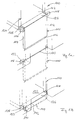
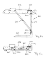
- Figure 1a shows sections of a car 120, with a Car floor 122, a car door opening 124 and one Car door sill 126.
- a car apron 110 In the area of the car door sill 126 is a car apron 110 according to the invention arranged.
- the car apron 110 essentially consists from a flat plate 112 which is essentially extends vertically down from the edge of the car door sill 126.
- the edges of plate 112 are for stabilization the plate folded over to side walls 114.
- the bottom edge 116 of the plate 112 is chamfered to - as already above explained - foot injuries to passengers who when a gap appears, carelessly put her foot into the gap have brought to prevent.
- the car apron 110 comprises on its the upper edge two opposite the lower edge 116 laterally cantilevered pin 118, which essentially one trapezoidal cross-section with downwards (i.e. in the direction of gravity) possessing rejuvenation.
- the cones 118 engage in complementary recesses 129 in support elements 128, which are in the area of the car door sill 126 perpendicular to the car door level from the car 120 stand out, and are in these recesses 129 against easy lifting locked.
- another suspension for example two bolts arranged one above the other, or vertical plate pieces or the like can be selected, the one with a horizontal application of force from the stop prevents the apron from yielding.
- the carrier elements 132 hold the car apron at the stop of the first floor 110 on their pin 118 and take it out of their previous one Holder in the recesses 129 of the (with the Car 120 moving down) support members 128 out.
- the car 120 has no car apron 110 enters the lowest stop.
- the pit in the bottom stop thus with a significantly reduced pit depth be designed.
- the second Car apron 140 is particularly firmly attached to the car door sill 126 arranged and consists essentially of a flat plate 142, the lower edge 144 to avoid beveled from injuries, especially foot injuries is.
- the height of the smaller car apron is 140 chosen so that they the decisive unlocking zone when descending corresponds, and is max. 350 mm (this Value therefore results that the readjustment in the stop and retracting with the door open in elevator systems in a range of maximum 350 mm above and below the Levels are allowed).
- this Value therefore results that the readjustment in the stop and retracting with the door open in elevator systems in a range of maximum 350 mm above and below the Levels are allowed).
- the size of the second smaller apron to the given conditions of permissible Adjust unlocking zone.
- the second smaller apron 140 can have a height those with a reduced shaft pit depth are no longer complete There is space in the pit when the car Approach the flush position in the lowest stop would like to.
- the second car apron be slidable in one piece or in multiple pieces, for example by means of elongated holes or telescopic displacement, or otherwise removed from the tread area be, for example by folding or pushing away.
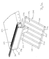
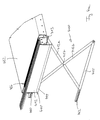
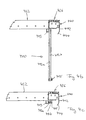
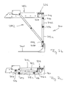
- Figure 2a shows a second embodiment of the invention Car apron.
- the in Figure 2 and all others Figures shown car aprons according to the invention are between an extended active position (shown in Figures 2a, 2b; 3a, 3b; 4a, 4b; 5a, 5b; 6a, 6b and 7a, 7b) and a retracted position for the lowest stop (shown in Figures 2c, 3c, 4c, 5c, 6c and 7c) pivotable, movable, adjustable, rotatable, etc.
- the retracted / folded position for the bottom stop is subsequently called the "shaft pit position" designated.
- FIG 2a shows a perspective view of the already mentioned car apron 210 according to a second embodiment the invention.
- Car apron 210 is below a car floor 222 and its associated car door sill 226 using a so-called four-bar linkage (Pantographs) 250, 252 attached (see also Figures 2b and 2c).
- the car apron 210 consists essentially of a grid 212 with upper and lower cross struts 213 and a plurality of longitudinal struts 215 connecting the cross struts 213.
- the joint elements 250, 252 of the four-bar linkage are in the illustrated embodiment plate-like elements, that used to form the lower joint axes between the two middle longitudinal struts 215 of the grille 212 of the car apron 210 are articulated. With their opposite The ends are the joint elements 250, 252 on the underside of the car floor 222 articulated (see FIG. 2b).
- the car apron 210 At the entrance of the with the car apron according to the invention 210 equipped cars in the lowest stop is the car apron 210 by means of the four-bar linkage 250, 252 as shown in Figure 2c in a pit position pivoted in which the grid 212 is substantially horizontal and flat on the underside of the car floor 222 is present.
- Horizontal lattice struts with the corresponding can also be equivalent Joint arrangement or arranged right and left Four-bar struts can be used.
- a second smaller one Car apron 240 which extends from the car door sill 226 extends substantially vertically downward and from a flat plate 242 with a bevel lower edge 244.
- the mode of action of the second smaller car apron 240 exists - as already above described - therein, injuries in the area of the unlocking zone to prevent. This function occurs in particular when entering the bottom stop, is also present in all other stops, however in the illustrated embodiment, the car apron 210 not perpendicular and flat from the car door sill extends downwards, but slightly oblique and with its upper area spaced apart from the car door level is arranged.
- the car apron 210 according to the second Embodiment of the invention thus no longer comes Double function - avoidance of injuries and avoidance of crashes in the shaft - to, but only that the latter function.
- the car apron is also sufficient for this 210, as shown in the figure, as Form grid 212, the struts set sufficiently tight are to prevent people from falling through and in particular To prevent children.
- the front of the car apron 210 also be formed in other ways, for example by a grille with cross struts that serve as climbing aid for from the Car can serve climbing people.
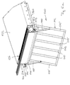
- the car apron of the second embodiment can of course, also be flat as a plate, such as this in the third embodiment of Figures 3a, 3b and 3c.
- the basic functioning of the car apron 310 shown in FIG third embodiment of the invention corresponds essentially that of the car apron 210 of the second Embodiment.
- the car apron shows 310 according to the third embodiment of the invention a flat design.
- the car apron includes 310 two plate-shaped elements 312a, 312b, which their longitudinal edges articulated to one another by means of hinges 317 are connected.
- the first plate 312a is one lower cross strut 313 provided by means of longitudinal struts 315 is connected to the four-bar linkage 350, 352.
- the second Plate 312b is in an area below the car door sill 326 (and behind a second smaller apron 340) articulated.
- the apron 310 can also consist of more than two Plate parts be assembled.
- the two plates 312a, 312b in one superimposed position can be pivoted and folded.
- the panels can be used to facilitate the folding process 312a, 312b, as shown in Figure 3a, central recesses 319a, 319b, in which are folded in Condition the four-bar strut can lay 350.
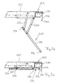
- Figure 4 shows a fourth embodiment of the invention Car apron 410, which is based on the scissor joint principle.
- the car apron 410 according to the invention comprises two cross struts 412a, 412b, which on their Crossing point 417 pivotally connected to each other are.
- first cross strut 413 and a second Cross strut 415 provided.
- the first cross strut 413 is on the underside of the car floor 422 in the area of the car door sill 426 arranged.
- At one end of the cross strut 413 is hinged one end of the scissor stay 412a, while the second end of the cross strut 413 as a guide groove is formed in the upper end of the second scissor stay 412b is guided horizontally.
- the cross strut 415 is freely suspended parallel to the first Cross brace 413 at opposite ends of the two scissor struts 412a, 412b arranged. This is the Scissor strut 412b articulated at one end of cross strut 415, while the scissor stay 412a with its free end horizontally displaceable in a guide groove 462 of the cross strut 415 is arranged.
- the car apron 410 before or when entering the lowest stop Collapse the scissor stays arranged like scissors 412a, 412b upwards to the underside of the car floor 422 and behind a second smaller car apron 440 folded (see Figures 4b and 4c).
- the second smaller one is again Car apron 440 to avoid crushing feet as a vertical plate 442 with a bevelled lower edge 444 trained.
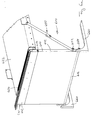
- FIG. 5a shows a car apron 510 according to a fifth Embodiment of the invention.
- Car apron 510 exists essentially of a grid 512 consisting of two Cross struts 513 and several, the two cross struts 513 connecting longitudinal struts 515, 515 'is formed, the two outer longitudinal struts 515 'over the upper of the two Cross struts are also extended.
- a car floor 522 At the bottom of a car floor 522 are two guide rails 560 provided, which is located in the edge area of the Car floor 522 from the car door sill 526 in the extend substantially perpendicular to the car door level to the rear.
- elongated longitudinal struts 515 At the top ends of the two over the top cross brace 513 elongated longitudinal struts 515 'is in each case one Roll element 517 arranged. Alternatively, everyone can Longitudinal struts 515 have the same length.
- the rolling elements 517 are each in one of the guide rails 560 Rolled so that the grid 512 of the car apron 510 along the guide rails 560 in one direction Movable and adjustable perpendicular to the plane of the car door is.
- a sliding guide can also be used be used.
- the car apron according to the invention comprises 510 swivel arms 550, which have a first end on longitudinal struts of the grid 512 (in the example shown to the outer longitudinal struts 515 ') and with their opposite End in a located below the car door sill 526 Section of the guide rails 560 on swivel axes 551 are articulated.
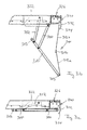
- FIG. 6a shows a car apron 610 according to a sixth Embodiment of the invention.
- the invention Car apron 610 includes a flat plate 612 that extends substantially vertically from the car door sill 626 extends flat down.
- the lateral (vertical) Edges of plate 612 are folded over to side walls 614, and a lower edge 616 is to avoid injury beveled.
- Plate 612 is on the underside of the car door sill 626 articulated in such a way that from its operative position, in which is essentially vertical from the car door sill 626 extends downward into one essentially horizontal chess pit position is pivotable in the it rests on the underside of the car floor 622 (cf. Figure 6c).
- rollers 652, 654 are provided in a lower area of the Side walls 614.
- the Roller pairs 652, 654 interact with curved rails 660, those in the car shaft in the area of the lowest stop, in particular in the shaft pit.
- one equipped with the apron 610 Car pairs the roller pairs 652, 654 the rails 660 as follows:
- the plate 612 is up to the edge plate 642 extending the car sleeper 626, which serves as the second smaller apron 640 (cf. figures 6a and 6b), a lower section 644 of the plate 642 is slanted to the rear.
- the beveled section 644 lies behind the plate 612 when it is in its vertical effective position (see dashed line of section 644 in Figure 6b), and is exposed, when the plate 612 is pivoted backwards. In the beveled section serves this exposed position 644 - as already explained above - to avoid of injuries.
- FIG. 7a shows a further car apron 710 according to one seventh embodiment of the invention.
- the one shown in Figure 7a The function of the car apron 710 is the same essentially the car apron shown in FIG. 6a 610 according to the sixth embodiment of the invention.
- the difference between these two car aprons is that that shown in Figure 7a Car apron 710 a two-part plate 712 for formation of the vertical apron surface.
- the two slats arranged one above the other like lamellae 712a, 712b are parallel to the apron surface horizontal axis pivotally connected to each other. Coaxial to this swivel axis are on the side the plate 712 additional rollers 756 arranged.
- the advantage of dividing the apron plate into several Sub-plates arranged one above the other is that the Apron surface not abruptly when the car descends, but successively / in sections from bottom to bottom is reduced above, so that always the largest possible Protection is given.
- an apron concept is thus proposed the at least one that can be deactivated if necessary Apron covers. Deactivating the at least one Apron is done by removing, retracting, pivoting, Twisting, compression etc. part of the apron concept according to the invention is further that the two protective measures a conventional car apron, namely avoidance of injuries in the area of the unlocking zones and avoiding falling into the shaft will be in a first apron, as described if necessary can be deactivated, and a second smaller one Apron, which in a conventional manner, but greatly shortened, is arranged on the car door sill and itself a short distance (depending on the height of the unlocking zone) extends under the car door sill.
- the slats on the right and left can also be connected to each other can be locked, this locking by a correspondingly attached element upon impact a deactivation device in succession or simultaneously can be solved.
- the so-called deactivation of the apron to avoid of crashes into the shaft includes any Type of apron removal, height displacement, the twisting, the pivoting etc.
- the essentially vertical apron a plurality of telescopically one inside the other or side by side movable slats to design when retracting to the bottom stop and hitting the Shaft pit floor shifted into each other or side by side become.
- the (smaller) second one Designing the apron to be height-adjustable, for example can be achieved by means of vertically arranged elongated holes can. The smaller apron is allowed for a pure height shift however not higher than the pit depth be otherwise a tripping edge arises.
- the apron can be made in one piece or, depending on the available space in the elevator shaft, be formed in several parts.
- the apron is preferably two on opposite Edges of the car floor perpendicular to the plane of the car door Rotation axes running along the two sides of the car provided, with each of the two apron parts around one axis of rotation can be rotated in the opposite direction is.
- the car apron has advantageously a circular segment shape, in particular Quarter circle segment shape.
- the apron can also be fitted with a corresponding sliding mechanism to the side or in two parts in both Sides are pushed.
- the car apron can be used to avoid this from falling into the shaft as a manually hooked one Sheet, net, slope, slide or the like executed his.
- this apron arranged on the underside of the car door sill and removed after the completion of the personal exemption and in stored near the elevator under lock or in the shaft.
- a self-exemption from the People located in the car through a car door lock be prevented.
- the large apron parts are always in the pit position (i.e. deactivated and in a substantially horizontal Alignment). This can be done in any mechanical or electrically, for example by means of a Holding magnets can be realized. This is about make sure that such trained apron parts only when needed be activated, for example by the Gravity, or by using a holding magnet is de-energized.
- the large aprons according to the invention can, depending on the type with different lattice shapes and additionally as required with means to increase security (nets, foils etc.).
- the aprons in the form of one or a number of Sheet metal plates, especially roller shutter-like, are available put.
Landscapes
- Cage And Drive Apparatuses For Elevators (AREA)
- Elevator Door Apparatuses (AREA)
- Body Structure For Vehicles (AREA)
Applications Claiming Priority (2)
| Application Number | Priority Date | Filing Date | Title |
|---|---|---|---|
| DE10002525 | 2000-01-21 | ||
| DE10002525 | 2000-01-21 |
Publications (3)
| Publication Number | Publication Date |
|---|---|
| EP1118576A2 true EP1118576A2 (fr) | 2001-07-25 |
| EP1118576A3 EP1118576A3 (fr) | 2002-04-10 |
| EP1118576B1 EP1118576B1 (fr) | 2005-04-06 |
Family
ID=7628284
Family Applications (1)
| Application Number | Title | Priority Date | Filing Date |
|---|---|---|---|
| EP01101225A Expired - Lifetime EP1118576B1 (fr) | 2000-01-21 | 2001-01-19 | Chasse-pieds pour cabine d'ascenceur |
Country Status (4)
| Country | Link |
|---|---|
| EP (1) | EP1118576B1 (fr) |
| AT (1) | ATE292597T1 (fr) |
| DE (1) | DE50105795D1 (fr) |
| ES (1) | ES2240244T3 (fr) |
Cited By (23)
| Publication number | Priority date | Publication date | Assignee | Title |
|---|---|---|---|---|
| EP1193210A1 (fr) * | 2000-08-31 | 2002-04-03 | Motala Hissar AB | Tôle chasse-pieds pour ascenseur |
| EP1215159A2 (fr) * | 2000-12-14 | 2002-06-19 | Kone Corporation | Tablier rétractable sous la cabine |
| DE10065101A1 (de) * | 2000-12-28 | 2002-07-18 | Logos Innovationen Gmbh | Aufzug mit einer Schutzvorrichtung |
| WO2002060802A2 (fr) * | 2001-01-31 | 2002-08-08 | Otis Elevator Company | Ensemble garde-pieds mobile pour ascenseur |
| DE10115990C1 (de) * | 2001-03-30 | 2002-10-10 | Reinhard Muth | Sicherheitssystem für einen Fahrstuhl |
| EP1524234A1 (fr) * | 2003-10-13 | 2005-04-20 | LM Liftmaterial GmbH | Système d'ascenseur |
| WO2005121014A2 (fr) * | 2004-06-07 | 2005-12-22 | Kone Corporation | Dispositif destine a un ascenseur |
| EP1772414A1 (fr) * | 2005-10-04 | 2007-04-11 | Wittur AG | Chasse-pieds pliable auto-bloquant pour cabine d'ascenseur |
| DE102006022407B3 (de) * | 2006-05-13 | 2007-08-23 | W & W Aufzugs- Und Industriekomponenten Gmbh & Co. Kg | Dreiteilige Teleskop-Fahrkorbschürze |
| US7350627B2 (en) | 2004-06-07 | 2008-04-01 | Kone Corporation | Elevator arrangement |
| FR2912390A1 (fr) * | 2007-02-13 | 2008-08-15 | Lyonnaise De Construction De M | Dispositif de protection pour un ascenseur et ascenseur comportant un tel dispositif |
| EP2308789A1 (fr) * | 2009-10-09 | 2011-04-13 | Prudhomme Sas | Chasse pieds pour ascenseur et son procédé de déploiement |
| CN102701057A (zh) * | 2012-03-13 | 2012-10-03 | 西子奥的斯电梯有限公司 | 一种可旋转轿厢护脚板 |
| WO2012137032A1 (fr) | 2011-04-05 | 2012-10-11 | Otis Elevator Company | Ensemble garde-pieds destiné à un système d'ascenseur |
| EP2688826A1 (fr) * | 2011-03-22 | 2014-01-29 | Otis Elevator Company | Ensemble garde-pieds pour système d'ascenseur |
| US8807288B1 (en) | 1999-04-22 | 2014-08-19 | Otis Elevator Company | Retractable toe guard |
| CN104326320A (zh) * | 2014-10-29 | 2015-02-04 | 康力电梯股份有限公司 | 一种伸缩轿厢护脚板 |
| CN108394799A (zh) * | 2017-11-09 | 2018-08-14 | 浙江西子重工机械有限公司 | 一种加固的护脚板装置 |
| CN108946389A (zh) * | 2018-08-31 | 2018-12-07 | 李安生 | 一种双户使用的多层楼房改造用电梯 |
| CN110407065A (zh) * | 2018-04-28 | 2019-11-05 | 中国建筑科学研究院有限公司建筑机械化研究分院 | 护脚板高度可调整装置及电梯装置系统 |
| WO2020260046A1 (fr) | 2019-06-28 | 2020-12-30 | Inventio Ag | Installation d'ascenseur comprenant un garde-pieds pouvant être appuyé sur des rails de guidage |
| WO2021063608A1 (fr) | 2019-09-30 | 2021-04-08 | Inventio Ag | Installation d'ascenseur |
| WO2021063962A1 (fr) | 2019-09-30 | 2021-04-08 | Inventio Ag | Système d'ascenseur |
Families Citing this family (3)
| Publication number | Priority date | Publication date | Assignee | Title |
|---|---|---|---|---|
| DE202011051638U1 (de) | 2011-10-14 | 2011-11-16 | Aufzugteile Bt Gmbh | Absturzschutz für Aufzugsanlagen |
| ES2902335T3 (es) | 2018-02-23 | 2022-03-28 | Otis Elevator Co | Sistema protector de pies de cabina de ascensor |
| ES2912314T3 (es) | 2018-08-10 | 2022-05-25 | Otis Elevator Co | Faldón de cabina de ascensor |
Citations (3)
| Publication number | Priority date | Publication date | Assignee | Title |
|---|---|---|---|---|
| CH431864A (de) * | 1966-03-09 | 1967-03-15 | Inventio Ag | Schutzvorrichtung an einem Aufzug |
| JPS5347650A (en) * | 1976-10-14 | 1978-04-28 | Mitsubishi Electric Corp | Apron of elevator cage |
| JPS60102386A (ja) * | 1983-11-04 | 1985-06-06 | 株式会社日立製作所 | エレベ−タ−かごの前だれ装置 |
-
2001
- 2001-01-19 DE DE50105795T patent/DE50105795D1/de not_active Expired - Lifetime
- 2001-01-19 AT AT01101225T patent/ATE292597T1/de active
- 2001-01-19 ES ES01101225T patent/ES2240244T3/es not_active Expired - Lifetime
- 2001-01-19 EP EP01101225A patent/EP1118576B1/fr not_active Expired - Lifetime
Patent Citations (3)
| Publication number | Priority date | Publication date | Assignee | Title |
|---|---|---|---|---|
| CH431864A (de) * | 1966-03-09 | 1967-03-15 | Inventio Ag | Schutzvorrichtung an einem Aufzug |
| JPS5347650A (en) * | 1976-10-14 | 1978-04-28 | Mitsubishi Electric Corp | Apron of elevator cage |
| JPS60102386A (ja) * | 1983-11-04 | 1985-06-06 | 株式会社日立製作所 | エレベ−タ−かごの前だれ装置 |
Non-Patent Citations (1)
| Title |
|---|
| PATENT ABSTRACTS OF JAPAN vol. 002, no. 080 (M-025), 24. Juni 1978 (1978-06-24) -& JP 53 047650 A (MITSUBISHI ELECTRIC CORP), 28. April 1978 (1978-04-28) * |
Cited By (52)
| Publication number | Priority date | Publication date | Assignee | Title |
|---|---|---|---|---|
| US8807288B1 (en) | 1999-04-22 | 2014-08-19 | Otis Elevator Company | Retractable toe guard |
| EP1193210A1 (fr) * | 2000-08-31 | 2002-04-03 | Motala Hissar AB | Tôle chasse-pieds pour ascenseur |
| EP1215159A2 (fr) * | 2000-12-14 | 2002-06-19 | Kone Corporation | Tablier rétractable sous la cabine |
| EP1215159A3 (fr) * | 2000-12-14 | 2003-12-10 | Kone Corporation | Tablier rétractable sous la cabine |
| DE10065101A1 (de) * | 2000-12-28 | 2002-07-18 | Logos Innovationen Gmbh | Aufzug mit einer Schutzvorrichtung |
| WO2002060802A2 (fr) * | 2001-01-31 | 2002-08-08 | Otis Elevator Company | Ensemble garde-pieds mobile pour ascenseur |
| WO2002060802A3 (fr) * | 2001-01-31 | 2002-10-24 | Otis Elevator Co | Ensemble garde-pieds mobile pour ascenseur |
| DE10115990C1 (de) * | 2001-03-30 | 2002-10-10 | Reinhard Muth | Sicherheitssystem für einen Fahrstuhl |
| EP1524234A1 (fr) * | 2003-10-13 | 2005-04-20 | LM Liftmaterial GmbH | Système d'ascenseur |
| WO2005040030A1 (fr) * | 2003-10-13 | 2005-05-06 | Lm Liftmaterial Gmbh | Systeme d'ascenseur |
| WO2005121014A3 (fr) * | 2004-06-07 | 2006-04-06 | Kone Corp | Dispositif destine a un ascenseur |
| US7350627B2 (en) | 2004-06-07 | 2008-04-01 | Kone Corporation | Elevator arrangement |
| WO2005121014A2 (fr) * | 2004-06-07 | 2005-12-22 | Kone Corporation | Dispositif destine a un ascenseur |
| EP1772414A1 (fr) * | 2005-10-04 | 2007-04-11 | Wittur AG | Chasse-pieds pliable auto-bloquant pour cabine d'ascenseur |
| DE102005047498B3 (de) * | 2005-10-04 | 2007-04-19 | Wittur Ag | Faltbare selbsthemmende Fahrkorbschürze |
| CN1982195B (zh) * | 2005-10-04 | 2010-05-12 | 维托公开股份有限公司 | 具有可折叠的自锁式轿厢裙板的电梯安全系统 |
| DE102006022407B3 (de) * | 2006-05-13 | 2007-08-23 | W & W Aufzugs- Und Industriekomponenten Gmbh & Co. Kg | Dreiteilige Teleskop-Fahrkorbschürze |
| EP1854758A1 (fr) | 2006-05-13 | 2007-11-14 | W+W Aufzugkomponenten GmbH u. Co. KG | Cabine d'ascenseur |
| FR2912390A1 (fr) * | 2007-02-13 | 2008-08-15 | Lyonnaise De Construction De M | Dispositif de protection pour un ascenseur et ascenseur comportant un tel dispositif |
| WO2008110696A1 (fr) * | 2007-02-13 | 2008-09-18 | Societe Lyonnaise De Construction De Materiel D'ascenseur - Slycma | Dispositif de protection pour un ascenseur et ascenseur comportant un tel dispositif |
| EP2308789A1 (fr) * | 2009-10-09 | 2011-04-13 | Prudhomme Sas | Chasse pieds pour ascenseur et son procédé de déploiement |
| FR2951148A1 (fr) * | 2009-10-09 | 2011-04-15 | Prudhomme Sa | Chasse pieds pour ascenseur et son procede de deploiement |
| CN103562110A (zh) * | 2011-03-22 | 2014-02-05 | 奥的斯电梯公司 | 用于电梯系统的护脚板组件 |
| EP2688826A4 (fr) * | 2011-03-22 | 2014-12-24 | Otis Elevator Co | Ensemble garde-pieds pour système d'ascenseur |
| CN103562110B (zh) * | 2011-03-22 | 2016-07-13 | 奥的斯电梯公司 | 用于电梯系统的护脚板组件 |
| EP2688826A1 (fr) * | 2011-03-22 | 2014-01-29 | Otis Elevator Company | Ensemble garde-pieds pour système d'ascenseur |
| US9227817B2 (en) | 2011-03-22 | 2016-01-05 | Otis Elevator Company | Toe guard assembly for an elevator system |
| US10005645B2 (en) | 2011-04-05 | 2018-06-26 | Otis Elevator Company | Toe guard assembly for an elevator system |
| EP2694418A4 (fr) * | 2011-04-05 | 2014-08-27 | Otis Elevator Co | Ensemble garde-pieds destiné à un système d'ascenseur |
| EP2694418A1 (fr) * | 2011-04-05 | 2014-02-12 | Otis Elevator Company | Ensemble garde-pieds destiné à un système d'ascenseur |
| CN103443011B (zh) * | 2011-04-05 | 2015-12-16 | 奥的斯电梯公司 | 用于电梯系统的护脚板组件 |
| WO2012137032A1 (fr) | 2011-04-05 | 2012-10-11 | Otis Elevator Company | Ensemble garde-pieds destiné à un système d'ascenseur |
| US20140020986A1 (en) * | 2011-04-05 | 2014-01-23 | Otis Elevator Company | Toe guard assembly for an elevator system |
| US9428365B2 (en) * | 2011-04-05 | 2016-08-30 | Otis Elevator Company | Toe guard assembly for an elevator system |
| CN103443011A (zh) * | 2011-04-05 | 2013-12-11 | 奥的斯电梯公司 | 用于电梯系统的护脚板组件 |
| CN102701057B (zh) * | 2012-03-13 | 2014-04-09 | 西子奥的斯电梯有限公司 | 一种可旋转轿厢护脚板 |
| CN102701057A (zh) * | 2012-03-13 | 2012-10-03 | 西子奥的斯电梯有限公司 | 一种可旋转轿厢护脚板 |
| CN104326320A (zh) * | 2014-10-29 | 2015-02-04 | 康力电梯股份有限公司 | 一种伸缩轿厢护脚板 |
| CN108394799A (zh) * | 2017-11-09 | 2018-08-14 | 浙江西子重工机械有限公司 | 一种加固的护脚板装置 |
| CN108394799B (zh) * | 2017-11-09 | 2023-11-21 | 杭州优迈科技有限公司 | 一种加固的护脚板装置 |
| CN110407065A (zh) * | 2018-04-28 | 2019-11-05 | 中国建筑科学研究院有限公司建筑机械化研究分院 | 护脚板高度可调整装置及电梯装置系统 |
| CN110407065B (zh) * | 2018-04-28 | 2022-04-29 | 中国建筑科学研究院有限公司建筑机械化研究分院 | 护脚板高度可调整装置及电梯装置系统 |
| CN108946389A (zh) * | 2018-08-31 | 2018-12-07 | 李安生 | 一种双户使用的多层楼房改造用电梯 |
| CN108946389B (zh) * | 2018-08-31 | 2023-12-15 | 黄河科技学院 | 一种双户使用的多层楼房改造用电梯 |
| WO2020260046A1 (fr) | 2019-06-28 | 2020-12-30 | Inventio Ag | Installation d'ascenseur comprenant un garde-pieds pouvant être appuyé sur des rails de guidage |
| CN114080366A (zh) * | 2019-06-28 | 2022-02-22 | 因温特奥股份公司 | 具有能够支撑在导轨上的轿厢裙板的电梯设备 |
| CN114080366B (zh) * | 2019-06-28 | 2024-04-23 | 因温特奥股份公司 | 具有能够支撑在导轨上的轿厢裙板的电梯设备 |
| WO2021063608A1 (fr) | 2019-09-30 | 2021-04-08 | Inventio Ag | Installation d'ascenseur |
| WO2021063962A1 (fr) | 2019-09-30 | 2021-04-08 | Inventio Ag | Système d'ascenseur |
| CN114531871A (zh) * | 2019-09-30 | 2022-05-24 | 因温特奥股份公司 | 电梯设备 |
| US11702320B2 (en) | 2019-09-30 | 2023-07-18 | Inventio Ag | Car skirt of an elevator installation |
| CN114531871B (zh) * | 2019-09-30 | 2023-11-17 | 因温特奥股份公司 | 电梯设备 |
Also Published As
| Publication number | Publication date |
|---|---|
| EP1118576B1 (fr) | 2005-04-06 |
| DE50105795D1 (de) | 2005-05-12 |
| ATE292597T1 (de) | 2005-04-15 |
| EP1118576A3 (fr) | 2002-04-10 |
| ES2240244T3 (es) | 2005-10-16 |
Similar Documents
| Publication | Publication Date | Title |
|---|---|---|
| EP1118576B1 (fr) | Chasse-pieds pour cabine d'ascenceur | |
| EP1772414B1 (fr) | Chasse-pieds pliable auto-bloquant pour cabine d'ascenseur | |
| EP3007953B1 (fr) | Paroi de protection pour la protection de personnes de véhicules ferroviaires en circulation | |
| EP2041385B1 (fr) | Dispositif pour portes coulissantes ou portails coulissants | |
| EP2641805B1 (fr) | Véhicule ferroviaire doté d'une entrée passagers conçue pour les personnes à mobilité réduite | |
| DE2330944A1 (de) | Tueranordnung fuer einen eisenbahnpersonenwagen | |
| DE102016123802A1 (de) | Laufschiene | |
| EP0641701B1 (fr) | Marchepieds pour véhicules ferroviaires | |
| DE102007022387B4 (de) | Ein- und Ausstiegshilfe für Fahrzeuge des Personenverkehrs | |
| AT409618B (de) | Überfahrrampe für rollstuhlfahrer in einem fahrzeug, insbesondere einem reisezugwagen mit niederflureinstiegen | |
| DE10065101A1 (de) | Aufzug mit einer Schutzvorrichtung | |
| DE4220803C2 (de) | Rolltreppeneinrichtung | |
| EP3538410B1 (fr) | Véhicule ferroviaire à sections d'espace intérieur situées à différentes hauteurs de plancher | |
| DE202004011076U1 (de) | Arbeitsbühne für Schienenfahrzeuge | |
| DE102008007059B4 (de) | Wagenkasten eines Schienenfahrzeugs mit Notfall-Ausstiegstür | |
| EP4087997B1 (fr) | Dispositif de stationnement équipé d'un ensemble de porte | |
| EP3169295A1 (fr) | Grille latérale à synchronisme | |
| EP0941896A1 (fr) | Hayon élévateur avec protection anti-encastrement réglable en hauteur | |
| DE68901816T2 (de) | Einstiegsanordnung mit einfahrbaren stufen fuer die ein- und ausstiegstuer eines eisenbahnfahrzeuges fuer den passagiertransport. | |
| DE102011018618B4 (de) | Einstieghilfe | |
| DE102014104072B4 (de) | Zusammenklappbares schienengeführtes Liftsystem | |
| DE2915262A1 (de) | Ueberfahrbruecke | |
| DE102009024426B3 (de) | Rolltor mit Anfahrsystem | |
| DE102011109900B3 (de) | Schrägaufzug insbesondere für Rollstühle mit faltbarer Plattform | |
| DE202023103983U1 (de) | Schwimmbecken mit Treppe |
Legal Events
| Date | Code | Title | Description |
|---|---|---|---|
| PUAI | Public reference made under article 153(3) epc to a published international application that has entered the european phase |
Free format text: ORIGINAL CODE: 0009012 |
|
| AK | Designated contracting states |
Kind code of ref document: A2 Designated state(s): AT BE CH CY DE DK ES FI FR GB GR IE IT LI LU MC NL PT SE TR |
|
| AX | Request for extension of the european patent |
Free format text: AL;LT;LV;MK;RO;SI |
|
| PUAL | Search report despatched |
Free format text: ORIGINAL CODE: 0009013 |
|
| AK | Designated contracting states |
Kind code of ref document: A3 Designated state(s): AT BE CH CY DE DK ES FI FR GB GR IE IT LI LU MC NL PT SE TR |
|
| AX | Request for extension of the european patent |
Free format text: AL;LT;LV;MK;RO;SI |
|
| 17P | Request for examination filed |
Effective date: 20020502 |
|
| AKX | Designation fees paid |
Free format text: AT BE CH CY DE DK ES FI FR GB GR IE IT LI LU MC NL PT SE TR |
|
| RAP1 | Party data changed (applicant data changed or rights of an application transferred) |
Owner name: THYSSENKRUPP AUFZUGSWERKE GMBH |
|
| 17Q | First examination report despatched |
Effective date: 20040331 |
|
| GRAP | Despatch of communication of intention to grant a patent |
Free format text: ORIGINAL CODE: EPIDOSNIGR1 |
|
| GRAS | Grant fee paid |
Free format text: ORIGINAL CODE: EPIDOSNIGR3 |
|
| GRAA | (expected) grant |
Free format text: ORIGINAL CODE: 0009210 |
|
| AK | Designated contracting states |
Kind code of ref document: B1 Designated state(s): AT BE CH CY DE DK ES FI FR GB GR IE IT LI LU MC NL PT SE TR |
|
| PG25 | Lapsed in a contracting state [announced via postgrant information from national office to epo] |
Ref country code: IT Free format text: LAPSE BECAUSE OF FAILURE TO SUBMIT A TRANSLATION OF THE DESCRIPTION OR TO PAY THE FEE WITHIN THE PRESCRIBED TIME-LIMIT;WARNING: LAPSES OF ITALIAN PATENTS WITH EFFECTIVE DATE BEFORE 2007 MAY HAVE OCCURRED AT ANY TIME BEFORE 2007. THE CORRECT EFFECTIVE DATE MAY BE DIFFERENT FROM THE ONE RECORDED. Effective date: 20050406 Ref country code: IE Free format text: LAPSE BECAUSE OF FAILURE TO SUBMIT A TRANSLATION OF THE DESCRIPTION OR TO PAY THE FEE WITHIN THE PRESCRIBED TIME-LIMIT Effective date: 20050406 Ref country code: FI Free format text: LAPSE BECAUSE OF FAILURE TO SUBMIT A TRANSLATION OF THE DESCRIPTION OR TO PAY THE FEE WITHIN THE PRESCRIBED TIME-LIMIT Effective date: 20050406 |
|
| REG | Reference to a national code |
Ref country code: GB Ref legal event code: FG4D Free format text: NOT ENGLISH |
|
| REG | Reference to a national code |
Ref country code: CH Ref legal event code: EP |
|
| REG | Reference to a national code |
Ref country code: IE Ref legal event code: FG4D Free format text: LANGUAGE OF EP DOCUMENT: GERMAN |
|
| REF | Corresponds to: |
Ref document number: 50105795 Country of ref document: DE Date of ref document: 20050512 Kind code of ref document: P |
|
| REG | Reference to a national code |
Ref country code: CH Ref legal event code: NV Representative=s name: BRAUNPAT BRAUN EDER AG |
|
| PG25 | Lapsed in a contracting state [announced via postgrant information from national office to epo] |
Ref country code: GR Free format text: LAPSE BECAUSE OF FAILURE TO SUBMIT A TRANSLATION OF THE DESCRIPTION OR TO PAY THE FEE WITHIN THE PRESCRIBED TIME-LIMIT Effective date: 20050706 Ref country code: DK Free format text: LAPSE BECAUSE OF FAILURE TO SUBMIT A TRANSLATION OF THE DESCRIPTION OR TO PAY THE FEE WITHIN THE PRESCRIBED TIME-LIMIT Effective date: 20050706 Ref country code: SE Free format text: LAPSE BECAUSE OF FAILURE TO SUBMIT A TRANSLATION OF THE DESCRIPTION OR TO PAY THE FEE WITHIN THE PRESCRIBED TIME-LIMIT Effective date: 20050706 |
|
| GBT | Gb: translation of ep patent filed (gb section 77(6)(a)/1977) |
Effective date: 20050721 |
|
| PG25 | Lapsed in a contracting state [announced via postgrant information from national office to epo] |
Ref country code: PT Free format text: LAPSE BECAUSE OF FAILURE TO SUBMIT A TRANSLATION OF THE DESCRIPTION OR TO PAY THE FEE WITHIN THE PRESCRIBED TIME-LIMIT Effective date: 20050908 |
|
| REG | Reference to a national code |
Ref country code: ES Ref legal event code: FG2A Ref document number: 2240244 Country of ref document: ES Kind code of ref document: T3 |
|
| REG | Reference to a national code |
Ref country code: IE Ref legal event code: FD4D |
|
| PG25 | Lapsed in a contracting state [announced via postgrant information from national office to epo] |
Ref country code: MC Free format text: LAPSE BECAUSE OF NON-PAYMENT OF DUE FEES Effective date: 20060131 Ref country code: LU Free format text: LAPSE BECAUSE OF NON-PAYMENT OF DUE FEES Effective date: 20060131 |
|
| PLBE | No opposition filed within time limit |
Free format text: ORIGINAL CODE: 0009261 |
|
| STAA | Information on the status of an ep patent application or granted ep patent |
Free format text: STATUS: NO OPPOSITION FILED WITHIN TIME LIMIT |
|
| ET | Fr: translation filed | ||
| 26N | No opposition filed |
Effective date: 20060110 |
|
| PG25 | Lapsed in a contracting state [announced via postgrant information from national office to epo] |
Ref country code: TR Free format text: LAPSE BECAUSE OF FAILURE TO SUBMIT A TRANSLATION OF THE DESCRIPTION OR TO PAY THE FEE WITHIN THE PRESCRIBED TIME-LIMIT Effective date: 20050406 |
|
| PG25 | Lapsed in a contracting state [announced via postgrant information from national office to epo] |
Ref country code: CY Free format text: LAPSE BECAUSE OF FAILURE TO SUBMIT A TRANSLATION OF THE DESCRIPTION OR TO PAY THE FEE WITHIN THE PRESCRIBED TIME-LIMIT Effective date: 20050406 |
|
| REG | Reference to a national code |
Ref country code: DE Ref legal event code: R082 Ref document number: 50105795 Country of ref document: DE Representative=s name: KUDLEK & GRUNERT PATENTANWAELTE, DE Ref country code: DE Ref legal event code: R082 Ref document number: 50105795 Country of ref document: DE Representative=s name: KUDLEK GRUNERT & PARTNER PATENTANWAELTE MBB, DE |
|
| REG | Reference to a national code |
Ref country code: FR Ref legal event code: PLFP Year of fee payment: 15 |
|
| PGFP | Annual fee paid to national office [announced via postgrant information from national office to epo] |
Ref country code: NL Payment date: 20150129 Year of fee payment: 15 |
|
| PGFP | Annual fee paid to national office [announced via postgrant information from national office to epo] |
Ref country code: ES Payment date: 20150128 Year of fee payment: 15 |
|
| PGFP | Annual fee paid to national office [announced via postgrant information from national office to epo] |
Ref country code: GB Payment date: 20150121 Year of fee payment: 15 Ref country code: FR Payment date: 20150122 Year of fee payment: 15 Ref country code: AT Payment date: 20150122 Year of fee payment: 15 |
|
| PGFP | Annual fee paid to national office [announced via postgrant information from national office to epo] |
Ref country code: BE Payment date: 20150121 Year of fee payment: 15 |
|
| PG25 | Lapsed in a contracting state [announced via postgrant information from national office to epo] |
Ref country code: BE Free format text: LAPSE BECAUSE OF NON-PAYMENT OF DUE FEES Effective date: 20160131 |
|
| REG | Reference to a national code |
Ref country code: AT Ref legal event code: MM01 Ref document number: 292597 Country of ref document: AT Kind code of ref document: T Effective date: 20160119 |
|
| GBPC | Gb: european patent ceased through non-payment of renewal fee |
Effective date: 20160119 |
|
| REG | Reference to a national code |
Ref country code: NL Ref legal event code: MM Effective date: 20160201 |
|
| REG | Reference to a national code |
Ref country code: FR Ref legal event code: ST Effective date: 20160930 |
|
| PG25 | Lapsed in a contracting state [announced via postgrant information from national office to epo] |
Ref country code: GB Free format text: LAPSE BECAUSE OF NON-PAYMENT OF DUE FEES Effective date: 20160119 |
|
| PG25 | Lapsed in a contracting state [announced via postgrant information from national office to epo] |
Ref country code: NL Free format text: LAPSE BECAUSE OF NON-PAYMENT OF DUE FEES Effective date: 20160201 Ref country code: FR Free format text: LAPSE BECAUSE OF NON-PAYMENT OF DUE FEES Effective date: 20160201 Ref country code: AT Free format text: LAPSE BECAUSE OF NON-PAYMENT OF DUE FEES Effective date: 20160119 |
|
| REG | Reference to a national code |
Ref country code: ES Ref legal event code: FD2A Effective date: 20170224 |
|
| PGFP | Annual fee paid to national office [announced via postgrant information from national office to epo] |
Ref country code: CH Payment date: 20170119 Year of fee payment: 17 Ref country code: DE Payment date: 20170120 Year of fee payment: 17 |
|
| PG25 | Lapsed in a contracting state [announced via postgrant information from national office to epo] |
Ref country code: ES Free format text: LAPSE BECAUSE OF NON-PAYMENT OF DUE FEES Effective date: 20160120 |
|
| REG | Reference to a national code |
Ref country code: CH Ref legal event code: PCAR Free format text: NEW ADDRESS: HOLEESTRASSE 87, 4054 BASEL (CH) |
|
| REG | Reference to a national code |
Ref country code: DE Ref legal event code: R119 Ref document number: 50105795 Country of ref document: DE |
|
| REG | Reference to a national code |
Ref country code: CH Ref legal event code: PL |
|
| PG25 | Lapsed in a contracting state [announced via postgrant information from national office to epo] |
Ref country code: DE Free format text: LAPSE BECAUSE OF NON-PAYMENT OF DUE FEES Effective date: 20180801 |
|
| PG25 | Lapsed in a contracting state [announced via postgrant information from national office to epo] |
Ref country code: LI Free format text: LAPSE BECAUSE OF NON-PAYMENT OF DUE FEES Effective date: 20180131 Ref country code: CH Free format text: LAPSE BECAUSE OF NON-PAYMENT OF DUE FEES Effective date: 20180131 |