EP1752979B1 - Mehrschichtiges informationsaufzeichnungsmedium, informationsaufzeichnungsvorrichtung und informationswiedergabevorrichtung - Google Patents
Mehrschichtiges informationsaufzeichnungsmedium, informationsaufzeichnungsvorrichtung und informationswiedergabevorrichtung Download PDFInfo
- Publication number
- EP1752979B1 EP1752979B1 EP05741465A EP05741465A EP1752979B1 EP 1752979 B1 EP1752979 B1 EP 1752979B1 EP 05741465 A EP05741465 A EP 05741465A EP 05741465 A EP05741465 A EP 05741465A EP 1752979 B1 EP1752979 B1 EP 1752979B1
- Authority
- EP
- European Patent Office
- Prior art keywords
- recording
- layer
- recording medium
- information recording
- information
- Prior art date
- Legal status (The legal status is an assumption and is not a legal conclusion. Google has not performed a legal analysis and makes no representation as to the accuracy of the status listed.)
- Expired - Lifetime
Links
Images


Classifications
-
- G—PHYSICS
- G11—INFORMATION STORAGE
- G11B—INFORMATION STORAGE BASED ON RELATIVE MOVEMENT BETWEEN RECORD CARRIER AND TRANSDUCER
- G11B7/00—Recording or reproducing by optical means, e.g. recording using a thermal beam of optical radiation by modifying optical properties or the physical structure, reproducing using an optical beam at lower power by sensing optical properties; Record carriers therefor
- G11B7/08—Disposition or mounting of heads or light sources relatively to record carriers
- G11B7/085—Disposition or mounting of heads or light sources relatively to record carriers with provision for moving the light beam into, or out of, its operative position or across tracks, otherwise than during the transducing operation, e.g. for adjustment or preliminary positioning or track change or selection
- G11B7/08505—Methods for track change, selection or preliminary positioning by moving the head
- G11B7/08511—Methods for track change, selection or preliminary positioning by moving the head with focus pull-in only
-
- G—PHYSICS
- G11—INFORMATION STORAGE
- G11B—INFORMATION STORAGE BASED ON RELATIVE MOVEMENT BETWEEN RECORD CARRIER AND TRANSDUCER
- G11B7/00—Recording or reproducing by optical means, e.g. recording using a thermal beam of optical radiation by modifying optical properties or the physical structure, reproducing using an optical beam at lower power by sensing optical properties; Record carriers therefor
- G11B7/24—Record carriers characterised by shape, structure or physical properties, or by the selection of the material
- G11B7/2403—Layers; Shape, structure or physical properties thereof
- G11B7/24035—Recording layers
- G11B7/24038—Multiple laminated recording layers
-
- G—PHYSICS
- G11—INFORMATION STORAGE
- G11B—INFORMATION STORAGE BASED ON RELATIVE MOVEMENT BETWEEN RECORD CARRIER AND TRANSDUCER
- G11B7/00—Recording or reproducing by optical means, e.g. recording using a thermal beam of optical radiation by modifying optical properties or the physical structure, reproducing using an optical beam at lower power by sensing optical properties; Record carriers therefor
- G11B2007/0003—Recording, reproducing or erasing systems characterised by the structure or type of the carrier
- G11B2007/0009—Recording, reproducing or erasing systems characterised by the structure or type of the carrier for carriers having data stored in three dimensions, e.g. volume storage
- G11B2007/0013—Recording, reproducing or erasing systems characterised by the structure or type of the carrier for carriers having data stored in three dimensions, e.g. volume storage for carriers having multiple discrete layers
-
- G—PHYSICS
- G11—INFORMATION STORAGE
- G11B—INFORMATION STORAGE BASED ON RELATIVE MOVEMENT BETWEEN RECORD CARRIER AND TRANSDUCER
- G11B7/00—Recording or reproducing by optical means, e.g. recording using a thermal beam of optical radiation by modifying optical properties or the physical structure, reproducing using an optical beam at lower power by sensing optical properties; Record carriers therefor
- G11B7/24—Record carriers characterised by shape, structure or physical properties, or by the selection of the material
- G11B7/2407—Tracks or pits; Shape, structure or physical properties thereof
- G11B7/24073—Tracks
- G11B7/24079—Width or depth
Definitions
- the present invention relates to a multi-layered structure of a multi-layered information recording medium (including a double-layered information recording medium), as well as to an information recording apparatus and an information reproducing apparatus for recording and reproducing information in and from the recording medium, respectively.
- Multi-layered information recording media are known as media capable of storing a large number of information items.
- double-layered DVD-ROM (video format) and double-layered DVD+R are standardized and put into practical use as multi-layered recording information media.
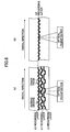
- FIG. 1 illustrates a general structure of a double-layered DVD+R.
- the double-layered DVD+R structure includes a first substrate 1, a semi-transmissive layer (L0) 2, an intermediate layer 3, a reflective metal film (L1) 4, and a second substrate 5, arranged in this order from the light incident surface.
- information signals are recorded as patterns of specific shapes in the surface of the semi-transmissive layer 2 or the reflective metal film 4.
- the first substrate 1 and the second substrate 5 are generally made of polycarbonate.
- the intermediate layer 3 is generally made of an ultraviolet-curable or thermal-curable resin.
- the semi-transmissive layer 2 is made of, for example, silicon, silver, or aluminum.
- the reflective metal film 4 is made of silver or aluminum as a major constituent.
- the disk thickness (the distance from the light incident surface to the recording layer) is different between a single-layer DVD+R and a double-layered DVD+R, both of which enable a user to read and write data in the disks, spherical aberration is generated.
- the track pitch is the same in the respective recording layers in the double-layered information recording medium illustrated in FIG. 2A and in the single-layer information recording medium, data recording quality and data reproduction quality are degraded when the same optical system is used without aberration correction means.
- Patent-related Publication 1 listed below discloses a technique for correcting spherical aberration by driving lenses other than the objective lens to change the optical magnification incident on the objective lens.
- Patent-related Publication 2 discloses a technique for correcting spherical aberration by shifting the phase of the light beam incident on the objective lens making use of the difference in refractive index of liquid crystal.
- Patent-related Publications 3-5 listed below disclose a technique for improving the initial accessing speed by allowing the spherical aberration correcting element to be perceived at the same position between a single-layer information recording medium and a double-layered information recording medium when these information recording media are set in a recording apparatus using the above-described spherical aberration correcting techniques.
- information recording media In recent years and continuing, there is a strong demand for further improvement in the reading and writing speed with respect to information recording media. It is also required for information recording media to have a structure for allowing high-speed access not only in the initial access speed, but also in the overall read/write speed.
- One method for reducing the read/write speed is to reduce the time required for inter-layer jumping (for allowing the focal spot of the light beam to jump between recording layers) during the reading and/or writing operations.
- Patent-related Publication 6 proposes not to use a spherical aberration correcting element, and instead, it proposes to change the information items (including the track pitch and the minimum mark length) recorded in each of the recording layers linearly with respect to the disk thickness of that recording layer, based on the relationship between the degradation of the spot size due to the difference in the disk thickness, and the information density relative to the spot size, in order to enable high-speed access and to maintain the signal quality the same in the respective recording layers.
- WO-A-03/065359 discloses an optical recording medium having a first light transmitting layer; a layer composed of an organic dye for recording and reading data by an optical beam of a first wavelength incident through the first light transmitting layer and transmitting an optical beam of a second wavelength incident through the first light transmitting layer; a second light transmitting layer for transmitting the optical beam of the second wavelength incident through the layer composed of the organic dye; and a reflecting layer for reflecting the optical beam of the second wavelength incident through the second light transmitting layer.
- the optical resolution changes greatly due to the spherical aberration caused by the variation (or the error) in the disk thickness, over the degradation of the spot size.
- the present invention was conceived in view of the above-described circumstances, and it is an object of the invention to provide a high-density and large-capacity multi-layered information recording medium that can reduce the inter-layer jumping time and can maintain the signal qualities of the respective recording layers substantially the same as that of a single-layer information medium. It is also an object of the invention to provide a small-sized information recording apparatus and a small-sized information reproducing apparatus suitable for recording and reproducing data in and from such a multi-layered information recording medium.
- the track pitch of each of the recording layers of a multi-layered information recording medium is determined by a quadratic function of distance from the light incident surface to the associated one of the recording layers (which distance is referred to as a "disk thickness").
- a multi-layered information recording medium comprises: three or more recording layers, characterised in that each recording layer has a guiding groove formed at a track pitch defined by a quadratic function of a distance from a light incidence surface to the associated recording layer; the recording layers include a reference recording layer at a distance from the light incidence surface closest to a distance from the light incidence surface of a single-layer information recording medium, and the track pitch of the guiding groove of the reference recording layer is the smallest amongst the recording layers; and each of the recording layers is useable for data recording and reproducing using an optical system having a wavelength of 400 nm to 420 nm and using an objective lens with NA value of 0.63 to 0.67.
- the track pitch Pi satisfies 1.9 ⁇ 10 - 5 ⁇ d ⁇ i - 600 2 + 0.45 ⁇ P ⁇ i where di denotes the disk thickness of each of the recording layers.
- the guiding groove of each of the recording layers is a spiral groove, and the track pitch of the spiral groove is determined such that the track pitch increases as the separation of the associated recording layer from the reference recording layer having the disk thickness closest to that of the single-layer information recording medium increases.
- the track pitches TPm and TPn of two adjacent recording layers satisfy TPm - TPn TPm ⁇ 0.043
- the track pitch of the guiding groove formed in each of the recording layers is set so as to achieve an optical resolution equivalent to the optical resolution (i.e., modulation transfer function: MTF) of the light spot in the radial direction of the recording layer of the single-layer information recording medium.
- MTF modulation transfer function
- the minimum mark length of a recording mark formed in each of the recording layer of a multi-layered information recording medium is determined by a quadratic function of the distance from the light incident surface to the associated recording layer (i.e., the disk thickness).
- the multi-layered information recording medium used in an information recording/reproducing apparatus applicable to both a single-layer information recording medium having a single recording layer on one side of that medium and an arbitrary multi-layered information recording medium having two or more recording layers on one side of that medium comprises: a plurality of recording layers, each recording layer having a guiding groove and recording marks formed in the guiding groove such that a minimum mark length is a quadratic function of a distance from the light incidence surface to the associated recording layer; wherein the plural recording layers include a reference recording layer at a distance from the light incidence surface closest to a distance from the light incidence surface the single-layer information recording medium, and the minimum mark length of the recording marks of the reference recording layer is the smallest amongst the plural recording layers.
- the minimum mark length Si satisfies 1.14 ⁇ 10 - 5 ⁇ d ⁇ i - 600 2 + 0.24 ⁇ S ⁇ i where di denotes the disk thickness of each of the recording layers.
- the guiding groove of each of the recording layers is a spiral groove, and the recording marks are formed in the spiral groove in such a manner that the minimum mark length increases as the separation of the associated recording layer from the reference recording layer increases.
- the minimum mark lengths Dm and Dn of two adjacent recording layers satisfy Dm - Dn Dm ⁇ 0.048
- the recording marks are formed based on the minimum mark length determined so as to achieve an optical resolution equivalent to the optical resolution (MTF) of the light spot in the tangential (data writing) direction of the recording layer of a single-layer information recording medium.
- MTF optical resolution
- the multi-layered information recording medium may have the features of both of the above-described first and second aspects.
- the multi-layered information recording medium has:
- one of the multiple recording layers has a disk thickness substantially equal to that of a single-layer information recording medium to realize a layered structure of large-capacity recording medium.
- the guiding groove of each of the recording layers has a wobble representing information unique to the recording medium.
- the wobble of each of the recording layers is shaped such that the ratio of the track pitch to the wobble displacement of the associated recording layer is equal to the ratio of the track pitch of a single-layer information recording medium to the wobble displacement of the single-layer information recording medium, or such that the ratio of the minimum mark length to the wobble frequency of the associated recording layer is equal to the ratio of the minimum mark length of a single-layer information recording layer to the wobble frequency of the single-layer information recording layer.
- wobble signals can be acquired from each of the recording layers of the multi-layered information recording medium at signal quality equal to that of a single-layer information recording medium.
- information about the track pitch or the minimum mark length is recorded as the wobble in each of the recording layers, or alternatively, an information area for recording the information about the track pitch or the minimum mark length is provided in each of the recording layers.
- high-speed servo controls can be carried out after inter-layer jumping.
- an information recording apparatus operative for both a single-layer information recording medium having a single recording layer on one side of the medium and a multi-layered information recording medium having three or more recording layers on one side of the medium, the apparatus comprises: a writing unit configured to write information in a multi-layered information recording medium having three or more recording layers, each of the recording layers being useable for data recording and reproducing using an optical system having a wavelength of 400 nm to 420 nm and using an objective lens with NA value of 0.63 to 0.67, by forming recording marks in each of multiple recording layers of the multi-layered information recording medium such that the minimum mark length of each of the recording layers is a quadratic function of a distance from a light incidence surface to the associated recording layer, and such that the minimum mark length of a reference recording layer at a distance from the light incidence surface closest to a distance from the light incidence surface of the single-layer information recording medium becomes the smallest amongst the multiple recording layers of the multi-layered information recording medium.
- the information recording apparatus is configured to increase a rotational speed of the multi-layered information recording medium as the separation of the currently processed recording layer from the reference recording layer becomes greater.
- the information recording apparatus may be configured to increase the time duration of the recording pulse as the separation of the currently processed recording layer from the reference recording layer becomes greater.
- an information reproducing apparatus for reproducing information from a multi-layer information recording medium.
- the information reproducing apparatus employs a differential push-pull method using a main beam and a sub-beam to perform track control, and changes the gain ratio of the push-pull signal generated by the sub-beam according to the track pitch of the guiding groove of each of the recording layers during the track control.
- FIG. 3 is a graph showing spatial frequency dependency of modulation transfer function (MTF) of a light spot in a radial direction of a multi-layered information recording medium according to an embodiment.
- the conditions of the graph of FIG. 3 are listed in Table 2. It is assumed that the spherical aberration of the information reproducing apparatus becomes the optimal for the disk thickness (which denotes the distance from the light incident surface to the recording layer) of 0.6 mm.
- TABLE 2 WAVELENGTH nm 405 NA - 0.65 INDEX OF REFRACTION - 1.621 RADIAL RIM - 0.5 TANGENTIAL RIM - 0.5
- the MTF of the light spot is degraded at both recording layers with the disk thickness greater than 0.6 mm (represented by the dark triangles and the dark squares in FIG. 3 ) and with the disk thickness smaller than 0.6 mm (represented by the white triangles and the white squares in FIG. 3 ).
- the spatial frequency of each of the recording layers is adjusted so as to achieve substantially the same resolution (MTF) in the radial direction as that of the recording layer of 0.6 mm disk thickness.
- the resolution (MTF) in the radial direction is defined by the track pitch, and the spatial frequency is one-cycle frequency of the track pitch. If an MTF at or above 0.18 is required, the track pitch of the recording layer can be determined so as to satisfy this condition at an arbitrary disk thickness.
- FIG. 4 is a graph showing the optimum track pitch as a function of disk thickness (i.e., the distance from the light incident surface to the recording layer) of an information recording layer measured under the same conditions as Table 1. It is understood from the graph that the optimum track pitch is given by a quadratic function of disk thickness.
- a guiding groove is formed in the recording layer L0 of a single-layer information recording medium so as to have the narrowest track pitch.
- the multi-layered information recording medium has recording layers whose disk thicknesses are different from that of the recording layer L0, and therefore, the optimum track pitch of the guiding groove of each of the recording layers is defined as a quadratic function of disk thickness derived from FIG. 4 .
- the track pitch has to satisfy condition (6).
- the acceptable range of the actual track pitch Pi be within 3% above the value defined by Equation (5).
- the acceptable range of the track pitch is illustrated in FIG. 5 .
- FIG. 6(a) is a cross-sectional view of the multi-layered information recording medium according to the first embodiment, which figure schematically illustrates the structure of the guiding grooves of multiple recording layers.
- the disk thickness (i.e., the distance from the light incident surface) of recording layer L0 of the multi-layered information medium is consistent with that of the single-layer information recording medium illustrated in FIG. 6(b) .
- the track pitch of that recording layer (L1 or L2) is increased along the quadratic curve.
- the track pitch increases in one direction (in which the disk thickness decreases) from the reference layer L0
- the invention is not limited to this example.
- the track pitch may increase in two directions from the reference layer L0 (in directions of increased disk thickness and decreased disk thickness), as illustrated in FIG. 7 .
- the signal quality of each of the recording layers can be maintained substantially the same as that of the single-layer information recording medium.
- the above-described structure may be applied to data recording and reproducing using an optical system having a wavelength of 400 nm to 420 nm and with an objective lens with NA value of 0.63 to 0.67.
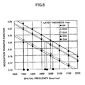
- FIG. 8 is a graph showing spatial frequency dependency of the modulation transfer function (MTF) of a light spot in the tangential direction (the data recording direction of a recording layer) of the multi-layered information recording medium according to the second embodiment of the invention.
- the measurement conditions are those shown in Table 2. It is assumed that the spherical aberration of the information reproducing apparatus becomes the optimum for the disk thickness of 0.6 mm.
- the MTF of the light spot in the tangential direction is degraded at both the recording layers with the disk thickness greater than 0.6 mm (represented by the dark triangles and the dark squares in FIG. 8 ) and with the disk thickness smaller than 0.6 mm (represented by the white triangles and the white squares in FIG. 8 ).
- the spatial frequency of each of the recording layers is adjusted direction so as to achieve substantially the same resolution (MTF) in the tangential direction as that of the recording layer of 0.6 mm disk thickness.
- the resolution (MTF) in the tangential direction is defined by the minimum mark length (or the minimum pit size) of the recording marks.
- the inverse of the minimum mark length is the spatial frequency in the tangential direction.
- the minimum unit of data in an optical disk is a channel bit length (1T), and the mark length is an integral multiple (nT) of the channel bit length.
- the minimum mark length of the recording layers can be determined so as to satisfy this condition at an arbitrary disk thickness.
- FIG. 9 is a graph showing the optimum values of the minimum mark length as a function of disk thickness (i.e., the distance from the light incident surface to the recording layer) of an information recording layer measured under the same conditions shown in FIG. 8 . It is understood from the graph that the optimum value of the minimum mark length is given as a quadratic function of disk thickness.
- pits are formed in the recording layer L0 of a single-layer information recording medium so as to have the smallest minimum mark length.
- the multi-layered information recording medium has recording layers whose disk thicknesses are different from that of the recording layer L0, and therefore, the optimum value of the minimum mark length of each of the recording layers is defined by a quadratic function of disk thickness derived from FIG. 9 .
- the minimum mark length Si ( ⁇ m) of the recording layer determined under the conditions of Table 2 is expressed by equation (7), using disk thickness di as a variable.
- S i 1.14 ⁇ 10 - 5 ⁇ d i - 600 2 + 0.24
- the minimum mark length has to satisfy condition (8).
- S i 1.14 ⁇ 10 - 5 ⁇ d i - 600 2 + 0.24
- the acceptable range of the minimum mark length Si is within 3% above the value defined by Equation (7).
- the acceptable range of the minimum mark length is illustrated in FIG. 10 .
- FIG. 11 schematically illustrates the minimum mark length in each of the recording layers of the multi-layered information recording medium according to the second embodiment. If the multi-layered information recording medium has a recording layer located at disk thickness R0, which is the same disk thickness as a single-layer information recording medium, the minimum mark length of that recording layer is consistent with that of the single-layer information recording medium. As the disk thickness deviates from R0 (R0 ⁇ R1 ⁇ R2, or R0>R1>R2), the minimum mark length increases in a quadratic manner.
- the signal quality of each of the recording layers can be maintained at the same level as that of the single-layer information recording medium.
- the above-described structure may be applied to data recording and reproducing using an optical system having a wavelength of 400 nm to 420 nm and using an objective lens with NA value of 0.63 to 0.67.
- the track pitch and the minimum mark length become the smallest when the recording layer L0 is located at disk thickness dO, as illustrated in FIG. 4 and FIG. 9 , respectively. Accordingly, by brining the disk thickness of any one of the recording layers of the multi-layered information recording medium consistent with that of the single-layer information recording medium, a large-capacity multi-layered information recording medium can be realized.
- the guiding groove formed in the single-layer information recording medium is slightly snaking in the radial direction. This is called a wobble, and is used to record unique information (such as absolute data time or address information) for this information recording medium.
- the clock can be used as a spindle rotation control clock or a recording clock. Accordingly, the structure of the PLL circuit can be simplified.
- the wobble frequency is set to an integral multiple of the channel bit length.
- the wobble frequency of DVD+R/RW (non-multiplied speed) is 32T which equals 818 kHz, and that of DVD-R/RW is 186T which equals 141 kHz.
- the wobble frequency is determined such that the ratio Fn/Cn (wobble frequency Fn to channel bit length Cn which is the minimum unit data length of the minimum mark length) becomes constant at each recording layer Ln.
- the ratio of the wobble frequency Fn to minimum mark length Tn (Fn/Tn) also becomes constant, as expressed in Equation (10).
- Fn Tn const This arrangement allows a spindle circuit clock and a recording clock to be generated for each of the recording layers using the same circuit.
- information about the track pitches and the minimum mark lengths, which information is unique to the information recording medium, is recorded in the wobble.
- An information recording apparatus of this embodiment reads the unique information from the wobble of each of the recording layers and writes this information in an information area of the associated one of the recording layers.
- Information about all of the recording layers may be recorded as the unique information of the multi-layered information recording medium in the information area of each of the recording layers.
- the unique information has been acquired in advance prior to accessing data of any one of the recording layers, and consequently, high-speed access can be achieved.
- FIG. 12 illustrates an example of the area structure of each of the recording layers of the multi-layered information recording medium.
- an information area (recording layer information area) for recording the information unique to this recording medium is provided in each of the recording layers, in place of forming a wobble.
- the parameter values of the recording/reproducing apparatus are determined based upon the signal acquired from the information area.
- the information unique to this multi-layered information recording medium which includes the track pitches and the minimum mark lengths of all the recording layers, may be recorded in each of the recording layers L0, L1, ..., Ln. Because the unique information has been acquired in advance whenever accessing any of the recording layers, high-speed access can be realized.
- FIG. 13 is a block diagram of an information recording apparatus 20 according to an embodiment of the invention. Explanation is made of how data are recorded in the above-described multi-layered information recording medium using the information recording apparatus 20 shown in FIG. 13 .
- a multi-layered information recording medium 10 is set in the information recording apparatus 20.
- the CPU 40 receives a recording request from the host apparatus 15 via the interface 38, a wobble signal is generated by the wobble signal detection circuit 28c, using the signal detected by the I/V amplifier 28a of the signal processing circuit 28, and the unique information of the multi-layered information recording medium 10 is decoded by the decoder 28e. Based on the decoded information, the CPU 40 calculates spindle rotation clock frequency, the recording clock frequency, and other parameters to define the conditions of the recording operation for each of the recording layers.
- the spindle rotation clock frequency is used as a control signal for controlling the rotation of the spindle motor 22 in accordance with the recording rate suitable for the associated recording layer (e.g., layer L0), and supplied to the spindle (SP) motor control circuit 26c of the control circuit 26.
- the recording clock frequency calculated from the minimum mark length of the associated recording layer (e.g., layer L0) is used as an operations clock of the encoder 25, or as a recording clock of the laser control circuit 24. In the latter case, a recording pulse string is generated according to the recording clock to irradiate the multi-layered information recording medium 10.
- the optical pickup device 23 first emits a reproducing light beam suitable for the recording layer L0 under the control of the laser control circuit 24 and performs focusing control and track control on the recording layer that has a disk thickness closest to the disk thickness R0 of the recording layer L0.
- the servo signal detection circuit 28b detects a track error signal and focusing error signal based on the output signal from the optical pickup device 23, and the pickup (PU) control circuit 26a of the control circuit 26 drives the tracking actuator and the focusing actuator of the optical pickup device 23.
- the optical pickup device 23 seeks information about the multi-layered information recording medium 10 in the information area and reads the data about the recording layers (including the track pitches and the minimum mark lengths) from the information area. Based on the readout data, the optical pickup device 23 determines the optimum recording pulse length or the optimum rotational speed of the spindle motor suitable for recording data in the current recording layer. The determined recording pulse length is supplied to the laser control circuit 24 to control the laser emission of the optical pickup device 23.
- the determined rotational speed of the spindle motor 22 is supplied from the CPU 40 to the SP motor control circuit 26c to control the rotational speed of the multi-layered information recording medium 10. Then, the laser emission power suitable for writing data in the recording layer is determined using the OPC (optimum power control) area.
- the signal processing circuit 28 acquires accurate address information from the wobble signal component of the output signal from the optical pickup device 23, and supplies the address information to the CPU 40.
- the CPU 40 causes the buffer manager 37 to store data supplied from the host apparatus 15 in the buffer RAM 34. If the amount of data accumulated in the buffer RAM 34 exceeds a prescribed level, the buffer manager 37 reports the excess accumulation to the CPU 40.
- the CPU 40 Upon receiving the report from the buffer manager 37, the CPU 40 instructs the encoder 25 to produce recording data, and at the same time, the CPU 40 causes the seek motor control circuit 26b of the control circuit 26 to output a seek instruction signal to the seek motor 21 so as to bring the optical pickup device 23 to the predetermined writing starting point.
- the CPU 40 also determines whether the optical pickup device 23 is at the writing starting position, based on the address information from the signal processing circuit 28. If the optical pickup device 23 is at the writing starting position, the CPU 40 allows the encoder 25 to record the produced writing data, by means of the laser control circuit 24 and the optical pickup device 23, in the data area of the multi-layered information recording medium 10. At this time, the unique information of the multi-layered information recording medium 10 acquired from the wobble signal is also recorded in the recording layer information area.
- the CPU 40 When receiving from the host apparatus 15 another recording request for data recording in another recording layer, the CPU 40 reports the change of the recording layer requested by the host apparatus 15 to the signal processing circuit 28.
- the optical pickup device 23 changes the focal position (i.e., inter-layer jumping) based on a focusing signal generated according to the number of recording layers of the multi-layered information recording medium 10 and supplied from the PU control circuit 26a.
- the CPU 40 suspends the recording operation, supplies an instruction for reproducing emission to the laser control circuit 24, and then operates the optical pickup device 23 again.
- the optical pickup device 23 reads the unique information (such as the track pitches or the minimum mark lengths) of the recording medium from the wobble signals. Based on the unique information, the optical pickup device 23 determined the optimum recording pulse width and the optimum spindle motor rotational speed for recording data in the recording layer of the multi-layered information recording medium 10. The optimum recording pulse width is supplied to the layer control circuit 24, which circuit then controls the laser emission of the optical pickup device 23.
- the rotational speed of the spindle motor 22 is supplied to the SP motor control circuit 26c to control the rotation of the multi-layered information recording medium 10. Then, the light emission power level suitable for the recording operation is determined using the OPC area.
- the actual recording operation is performed according to the above-described process.
- the apparatus so as to perform data recording starting from the reference layer having the disk thickness closest to that of the single-layer information recording medium, the recording order is clearly defined in advance, and therefore, an efficient recording operation is realized, while minimizing inter-layer jumping.
- a differential push-pull method is often used for track control during the recording operation for the multi-layered information recording medium.
- three beams are used to forms a main spot and two sub-spots, as illustrated in FIG. 14 , and the push-pull signals acquired from the three beams are calculated so as to obtain a tracking signal that has little offset even if misalignment of the optical axis has occurred.
- the sub-spot is going to be offset from the land and the MPP/SPP ratio may vary.
- the K value representing the ratio of the light quantity of the main spot to the total light quantity of the two sub-spots is varied as the gain Kn of the sub-push-pull, depending on the currently processed recording layer.
- the track pitch and the minimum mark length (or the interval) become less dense, and therefore, the data recording capacity decreases. According, by starting data recording from the recording layer with the disk thickness closest to the reference thickness R0, a large amount of data recording can be achieved with less inter-layer jumping.
- the spindle rotational speed has to be determined so as to be suitable for the minimum mark length of the associated recording layer.
- the spindle rotational speeds of the respective recording layers satisfy the relationship A ⁇ 0 ⁇ A ⁇ 1 ⁇ ... ⁇ An .
- the recording clock frequency may be adjusted by controlling pulse duration, in place of controlling the spindle rotational speed, to perform optimum recording.
- the pulse durations satisfy the relationship T ⁇ 0 ⁇ T ⁇ 1 ⁇ ... ⁇ Tn .
- each recording layer has a spiral guiding groove.
- the spatial frequency characteristic of the MTF of the light spot in the radial direction of the multi-layered information recording medium of the third embodiment is one illustrated in FIG. 3 .
- the conditions are listed in Table 3.
- TABLE 3 WAVELENGTH nm 405 NA 0.65 L0 DISK THICKNESS mm 0.6 L1 DISK THICKNESS mm 0.575 INDEX OF REFRACTION 1.621 RADIAL RIM 0.5 TANGENTIAL RIM 0.5
- the MTF of the light spot is degraded at both recording layers with the disk thickness greater than 0.6 mm (represented by the dark triangles and the dark squares in FIG. 3 ) and with the disk thickness smaller than 0.6 mm (represented by the white triangles and the white squares in FIG. 3 ).
- the spatial frequency of each of the recording layers is adjusted so as to achieve substantially the same resolution (MTF) in the radial direction as that of the recording layer of 0.6 mm disk thickness.
- the resolution (MTF) in the radial direction is defined by the track pitch, and the spatial frequency is one-cycle frequency of the track pitch. If an MTF at or above 0.18 is required, the track pitch of the recording layer can be determined so as to satisfy this condition at an arbitrary disk thickness.
- FIG. 4 is a graph showing the optimum track pitch as a function of disk thickness (i.e., the distance from the light incident surface to the recording layer) of an information recording layer measured under the same conditions as Table 3.
- the recording layer L0 of the single-layer information recording medium has a guiding groove formed at the narrowest track pitch.
- the multi-layered information recording medium has recording layers with disk thicknesses different from that of the recording layer L0, and therefore, the optimum track pitch of the guiding groove of each of the recording layers is set slightly broader than the track pitch of the single-layer recording medium.
- the disk thickness of the recording layer L0 of the single-layer information recording medium is R0
- the multi-layered information recording medium has a reference recording layer L0 with a disk thickness R0
- other recording layers L1, ..., Ln (where n is a natural number) have disk thicknesses R1, ..., Rn separated from the reference layer L0.
- the track pitches of the respective recording layers are P0, P1, ..., Pn
- the guiding grooves formed in the multi-layered information recording medium satisfy the condition P ⁇ 0 ⁇ P ⁇ 1 ⁇ ... ⁇ Pn .
- the spiral guiding grooves formed in the recording layers of the multi-layered information medium of the third embodiment have the cross-sectional structures shown in FIG. 6(a) .
- the track pitch of the recoding layer L0 having a disk thickness (i.e., the distance from the light incident surface) equal to that of the recording layer of the single-layer information recording medium shown in FIG. 6(b) is consistent with the track pitch of the single-layer information recording medium.
- the track pitch of that recording layer L1 or L2 is increased.
- n sp is index of refraction between adjacent recording layers
- NA obj is the numerical aperture of the objective lens
- NA det is the numerical aperture of the detection lens
- L d is the length on a side of a light-receiving element (assuming that the light-receiving element is square).
- the disk thickness of the m-th recording layer adjacent to the n-th recording has to be at or above 0.6303 mm. If the track pitch of the n-th recording layer is TPn, and if the track pitch of the adjacent (m-th) recoding layer is TPm, then the flare from the adjacent recording layers can be reduced, while achieving sufficient MTF at each of the recording layers, by satisfying the condition defined in expression (20). TPm - TPn TPm ⁇ 0.043
- the recording layers may be arranged so as to be closer to the light incident surface (with the decreasing disk thickness) as compared to the reference layer.
- the recording layers may be arranged so as to be away from the light incident surface (with the increasing disk thickness) as compared to the reference layer.
- the recording layers may be arranged on both sides of the reference layer in directions of decrease and increase of the disk thickness, as illustrated in FIG. 7(a) and FIG. 7(b) .
- the signal quality in the radial direction of each of the recording layers of the multi-layered information medium, each layer having a spiral guiding groove can be maintain equivalent to that of the single-layer information recording medium.
- FIG. 8 is a graph showing spatial frequency dependency of the modulation transfer function (MTF) of a light spot in the tangential direction (the data recording direction of a recording layer) of the multi-layered information recording medium.
- the measurement conditions are those shown in Table 3. It is assumed that the spherical aberration of the information reproducing apparatus becomes the optimum for the disk thickness of 0.6 mm.
- the MTF of the light spot in the tangential direction is degraded at both the recording layers with the disk thickness greater than 0.6 mm (represented by the dark triangles and the dark squares in FIG. 8 ) and with the disk thickness smaller than 0.6 mm (represented by the white triangles and the white squares in FIG. 8 ).
- the spatial frequency of each of the recording layers is adjusted direction so as to achieve substantially the same resolution (MTF) in the tangential direction as that of the recording layer of 0.6 mm disk thickness.
- the resolution (MTF) in the tangential direction is defined by the minimum mark length (or the minimum pit size) of the recording marks.
- the inverse of the minimum mark length is the spatial frequency in the tangential direction.
- the bit linear density is a channel bit length (1T), and the mark linear density is an integral multiple (nT) of the channel bit length.
- the minimum mark length of the recording layers can be determined so as to satisfy this condition at an arbitrary disk thickness.
- the relationship between the optimum value of the minimum mark length and disk thickness under the conditions shown in Table 3 is one shown in FIG 9 .
- the disk thickness of the recording layer L0 of the single-layer information recording medium is R0
- the multi-layered information recording medium has a reference recording layer L0 with a disk thickness R0
- other recording layers L1, ..., Ln (where n is a natural number) have disk thicknesses R1, ..., Rn separated from the reference layer L0. If the minimum mark lengths of the respective recording layers are D0, D1, ..., Dn, then the pits formed in the multi-layered information recording medium satisfy the condition D ⁇ 0 ⁇ D ⁇ 1 ⁇ ... ⁇ Dn .
- the configuration of the minimum mark length of each of the recording layers of the multi-layered information recording medium of the fourth embodiment is shown in FIG. 6 . If the multi-layered information recording medium has a reference recording layer having the disk thickness R0 equal to that of the single-layer information recording medium, the minimum mark length of this reference recording layer is the same as that of the single-layer information recording medium. As the position of the recording layer is separated from the reference recording layer L0, the minimum mark length of the recording layer is increased.
- the signal quality in the tangential direction of each of the recording layers of the multi-layered information medium can be maintain equivalent to that of the single-layer information recording medium.
- time required to perform correction for spherical aberration can be eliminated during the inter-layer jumping control. Consequently, a high-speed accessible multi-layered information recording medium of a spiral type can be provided.
- the track pitch and the minimum mark length become the smallest at the recording layer L0 with disk thickness R0, as illustrated in FIGs. 4 , 5 , 9 , and 10 . Accordingly, by setting the disk thickness of any one of the recording layers equal to that of a single-layer information recording medium, a large-capacity multi-layered information recording medium can be realized.
- the guiding groove in which pits are formed is slightly snaking in the radial direction. This is called a wobble, and is used to record unique information (such as absolute data time or address information) for this information recording medium.
- unique information such as absolute data time or address information
- the track pitches of the recording layers Ln may differ from each other.
- the wobble displacement of each recording layer is determined such that the ratio of the wobble displacement Wn to the track pitch Pn (Wn/Pn) becomes constant throughout the recording layers.
- a clock of an integral multiple is generated from the wobble signal by a phase locked loop (PLL) circuit, it can be used as a spindle rotation control clock or a recording clock. Accordingly, the structure of the PLL circuit can be simplified.
- PLL phase locked loop
- the wobble frequency is set to an integral multiple of the channel bit length.
- the wobble frequency of DVD+R/RW (non-multiplied speed) is 32T which equals 818 kHz, and that of DVD-R/RW is 186T which equals 141 kHz.
- the wobble frequency is determined such that the ratio Wn/Cn (wobble frequency Wn to channel bit length Cn which is the minimum unit data length of the minimum mark length) becomes constant at each recording layer Ln. Consequently, a spindle circuit clock and a recording clock can be generated for each of the recording layers using the same circuit.
- information about the track pitches and the minimum mark lengths, which information is unique to the information recording medium, is recorded in the wobble.
- An information recording apparatus of this embodiment reads the unique information from the wobble of each of the recording layers and writes this information in a recording layer information area of the associated one of the recording layers.
- the arrangement of the recording layer information area is, for example, one illustrated in FIG. 12 .
- the parameter values of the recording/reproducing apparatus are determined based upon the signal acquired from the recording layer information area.
- the information recording apparatus for performing recording operations on a spiral-type multi-layered information recording medium has a structure shown in the block diagram of FIG. 13 .
- the CPU 40 When a multi-layered information recording medium 10 is set in the information recording apparatus 20, and when the CPU 40 receives a recording request from the host apparatus 15 via the interface 38, the CPU 40 generates a control signal for controlling the rotation of the spindle motor 22 so as to be suitable for the rotation of the recording layer L0, based on the wobble signal from the signal processing circuit 28.
- a wobble signal is generated by the wobble signal detection circuit 28c, using the signal detected by the I/V amplifier 28a of the signal processing circuit 28, and the unique information of the multi-layered information recording medium 10 is decoded by the decoder 28e.
- the CPU 40 Based on the decoded information, the CPU 40 outputs the generated control signal to the spindle motor (SP motor) control circuit 26c of the control circuit 26, and at the same time, the CPU 40 reports the receipt of the recording request from the host apparatus 15 to the signal processing circuit 28. The reported information is processed at the RF signal detection circuit 28d.
- SP motor spindle motor
- the track pitch and the minimum mark length become less dense as the associated recording layer is further separated from the position (at disk distance R0) of the recording layer of the signal-layer information recording medium, the recording capacity of the recording layer decreases along with the increased separation.
- the spindle rotational speed has to be determined so as to be suitable for the minimum mark length of the associated recording layer.
- the spindle rotational speeds of the respective recording layers satisfy the relationship A ⁇ 0 ⁇ A ⁇ 1 ⁇ ... ⁇ An .
- the above-described structure is only an example, and at least a portion of the structure realized by execution of the program by the CPU 40 may be realized by a hardware structure.
- the optimum recording control may be performed by setting an appropriate pulse duration for each of the recording layers, in place of controlling the spindle rotational speed.
- the pulse durations satisfy the relationship T ⁇ 0 ⁇ T ⁇ 1 ⁇ ... ⁇ Tn .
- the information recording apparatus In the recording operation for a spiral-type multi-layered information medium, the information recording apparatus often uses a differential push-pull method for track control.
- the differential push-pull method three beams are used to form a main spot and two sub-spots, as illustrated in FIG. 14 , and the push-pull signals acquired from the three beams are calculated so as to obtain a tracking signal that has little offset even if misalignment of the optical axis has occurred.
- This arrangement is applicable not only to the operations performed under the conditions shown in Table 3, but also data recording and reproducing performed using an optical system having a wavelength of 400 nm to 420 nm and with an objective lens with a NA value of 0.63 to 0.67.
- the present invention is also suitably applied to a multi-layered information recording medium that requires signal processing so as to achieve the substantially the same signal quality at each of the recording layers as that of the single-layer information recording medium.
- the invention is also applicable to an information recording apparatus and an information reproducing apparatus capable of recording and reproducing data in and from the above-described multi-layered information recording medium.
Landscapes
- Optical Recording Or Reproduction (AREA)
- Optical Record Carriers And Manufacture Thereof (AREA)
Claims (27)
- Mehrschichtiges Informationsaufzeichnungsmedium, umfassend:drei oder mehr Aufzeichnungsschichten (L0-L4),dadurch gekennzeickxnet, dassjede Aufzeichnungsschicht (L0-L4) eine Führungsrille aufweist, die an einer Spurgangshöhe gebildet ist, die durch eine quadratische Funktion einer Distanz von einer Lichteintreffoberfläche zu der assoziierten Aufzeichnungsschicht (L0-L4) definiert ist;die Aufzeichnungsschichten (L0-L4) eine Referenz-Aufzeichnungsschicht (L0) enthalten, die Spurgangshöhe der Führungsrille der Referenz-Aufzeichnungsschicht (L0) die kleinste unter den Aufzeichnungsschichten (L0-L4) ist; undjede der Aufzeichnungsschichten (L0-L4) für Datenaufzeichnung und -reproduktion unter Verwendung eines optischen Systems mit einer Wellenlänge von 400 nm bis 420 nm und unter Verwendung einer Objektivlinse mit einem NA-Wert von 0,63 bis 0,67 verwendbar ist.
- Mehrschichtiges Informationsaufzeichnungsmedium nach Anspruch 1, wobei die Spurgangshöhe Pi jeder der Aufzeichnungsschichten (L0-L4)

erfüllt, wobei di die Distanz von der Lichteintreffoberfläche zu der assoziierten Aufzeichnungsschicht (L0-L4) bezeichnet, - Mehrschichtiges Informationsaufzeichnungsmedium nach Anspruch 1, wobei die Führungsrille jeder der Aufzeichnungsschichten (L0-L4) eine spiralförmige Rille ist und wobei die Spurgangshöhe der spiralförmigen Rille derart bestimmt wird, dass die Spurgangshöhe zunimmt, wenn die Trennung der assoziierten Aufzeichnungsschicht (L0. L4) von der Referenz-Aufzeichnungsschicht (L0) zunimmt.
- Mehrschichtiges Informationsaufzeichnungsmedium nach Anspruch 1, wobei die Spurgangshöhen TPm und TPn von jeweiligen zwei angrenzenden m-ten und n-ten Aufzeichnungsschichten (L0-L4)

erfüllen. - Mehrschichtiges Informationsaufzeichnungsmedium nach einem der Ansprüche 1 bis 4, wobei die Spurgangshöhe der Führungsrille, die in jeder der Aufzeichnungsschichten (L0-L4) gebildet ist, so eingestellt ist, um eine optische Auflösung, die äquivalent zu der optischen Auflösung oder einer Modulationsübertragungsfunktion eines Lichtpunkts in einer radialen Richtung der Aufzeichnungsschicht des Einzelschicht-Informationsaufzeichnungsmedium ist, zu erreichen.
- Verwendung eines mehrschichtigen Informationsaufzeichnungsmedium nach Anspruch 1 in einer Informationsaufzeichnungs/-reproduktionsvorrichtung, anwendbar auf sowohl ein Einzelschicht-Informationsaufzeichnungsmedium mit einer einzelnen Aufzeichnungsschicht auf einer Seite jenes Mediums als auch ein beliebiges mehrschichtiges Informationsaufzeichnungsmedium mit zwei oder mehr Aufzeichnungsschichten (L0-L4) auf einer Seite jenes Mediums, das mehrschichtige Informationsaufzeichnungsmedium umfassend:eine Vielzahl von Aufzeichnungsschichten (L0-L4), wobei jede Aufzeichnungsschicht (L0-L4) eine Führungsrille und Aufzeichnungsmarkierungen aufweist, die in der Führungsrille derart gebildet sind, dass eine minimale Markierungslänge eine quadratische Funktion einer Distanz von der Lichteintreffoberfläche zu der assoziierten Aufzeichnungsschicht (L0-L4) ist;wobei die mehreren Aufzeichnungsschichten (L0-L4) eine Referenz-Aufzeichnungsschicht (L0) in einer Distanz von der Lichteintreffoberfläche am nächsten zu einer Distanz von der Lichteintreffoberfläche des Einzelschicht-Informationsaufzeichnungsmediums enthalten und die minimale Markierungslänge der Aufzeichnungsmarkierungen der Referenz-Aufzeichnungsschicht (L0) die kleinste unter den mehreren Aufzeichnungsschichten (L0-L4) ist.
- Verwendung eines mehrschichtigen Informationsaufzeichnungsmediums nach Anspruch 6, wobei, wenn ein optisches Systems mit einer Wellenlänge von 400 nm bis 420 nm und mit einer Objektivlinse mit einem NA-Wert von 0,63 bis 0,67 für Datenaufzeichnung und -reproduktion des mehrschichtigen Informationsaufzeichnungsmediums verwendet wird, die minimale Markierungslänge Si jeder der Aufzeichnungsschichten

erfüllt, wobei di die Distanz von der Lichteintreffoberfläche zu der assoziierten Aufzeichnungsschicht (L0-L4) bezeichnet. - Verwendung eines mehrschichtigen Informationsaufzeichnungsmediums nach Anspruch 6, wobei die Führungsrille jeder der Aufzeichnungsschichten (L0-L4) eine spiralförmige Rille ist und die Aufzeichnungsmarkierungen in der spiralförmigen Rille der assoziierten Aufzeichnungsschicht (L0-L4) in einer derartigen Weise gebildet werden, dass die minimale Markierungslänge zunimmt, wenn die Trennung der assoziierten Aufzeichnungsschicht (L0-L4) von der Referenz-Aufzeichnungsschicht (L0) zunimmt.
- Verwendung eines mehrschichtigen Informationsaufzeichnungsmediums nach Anspruch 6, wobei die minimalen Markierungslängen Dm und Dn von jeweiligen zwei angrenzenden m-ten und n-ten Aufzeichnungsschichten

erfüllen. - Verwendung eines mehrschichtigen informationsaufzeichnungsrmediums nach einem der Ansprüche 6 bis 9, wobei für die Aufzeichnungsmarkierungen, die in jeder der Aufzeichnungsschichten (L0-L4) gebildet werden, die minimale Markierungslänge derart bestimmt wird, um eine optische Auflösung, die äquivalent zu der optischen Auflösung oder einer Modulationsübertragungsfunktion eines Lichtpunkts in einer Datenschreibrichtung der Aufzeichnungsschicht (L0-L4) des Einzelschicht-Informationsaufzeichnungsmediums ist, zu erreichen.
- Mehrschichtiges Informationsaufzeichnungsmedium nach Anspruch 1, wobei:jede der Aufzeichnungsschichten (L0-L4) Aufzeichnungsmarkierungen aufweist, die in der Führungsrille gebildet werden, wobei die Führungsrille Aufzeichnungsmarkierungen mit einer minimalen Markierungslänge aufweist, die durch eine quadratische Funktion einer Distanz einer Lichteintreffoberfläche zu der assoziierten Aufzeichnungsschicht (L0-L4) bestimmt wird;wobei die minimale Markierungslänge der Aufzeichnungsmarkierungen der Referenz-Aufzeichnungsschicht (L0) die kleinsten unter den mehreren Aufzeichnungsschichten (L0-L4) sind.
- Mehrschichtiges Informationsaufzeichnungsmedium nach Anspruch 11, wobei die Führungsrille jeder der Aufzeichnungsschichten (L0-L4) eine spiralförmige Rille ist und die Spurgangshöhe der spiralförmigen Rille zunimmt, wenn die Trennung der assoziierten Aufzeichnungsschicht (L0-L4) von der Referenz-Aufzeichnungsschicht (L0) zunimmt.
- Mehrschichtiges Informationsaufzeichnungsmedium nach Anspruch 11, wobei die Führungsrille jeder der Aufzeichnungsschichten (L0-L4) eine spiralförmige Rille ist und die minimale Markierungslänge der Aufzeichnungsmarkierungen, die in der spiralförmigen Rille gebildet werden, zunimmt, wenn die Trennung der assoziierten Aufzeichnungsschicht (L0-L4) von der Referenzschicht (L0) zunimmt.
- Verwendung eines mehrschichtigen Informationsaufzeichnungsmediums nach Anspruch 6, wobei die Referenz-Aufzeichnungsschicht (L0) sich in einer Distanz von der Lichteintreffoberfläche gleich der Distanz von der Lichteintreffoberfläche des Einzelschicht-Informationsaufzeichnungsmediums befindet.
- Verwendung eines mehrschichtigen Informationsaufzeichnungsmediums nach Anspruch 6, wobei die Führungsrille jeder der Aufzeichnungsschichten (L0-L4) ein Taumeln aufweist, das eindeutige Informationen repräsentiert, und das Taumeln jeder der Aufzeichnungsschichten (L0-L4) derart definiert ist, dass das Verhältnis der Spurgangshöhe der assoziierten Aufzeichnungsschicht (L0-L4) zu dem Taumelversatz gleich dem Verhältnis der Spurgangshöhe des Einzelschicht-Informationsaufzeichnungsmediums zu dem Taumelversatz des Einzelschicht-Informationsaufzeichnungsmediums ist.
- Verwendung eines mehrschichtigen Informationsaufzeichnungsmediums nach Anspruch 6, wobei die Führungsrille jeder der Aufzeichnungsschichten (L0-L4) ein Taumeln aufweist, das eindeutige Informationen repräsentiert, und das Taumeln jeder der Aufzeichnungsschichten (L0-L4) derart definiert ist, dass das Verhältnis der minimalen Markierungslänge der assoziierten Aufzeichnungsschicht (L0-L4) zu der Taumelfrequenz gleich dem Verhältnis der minimalen Markierungslänge des Einzelschicht-Informationsaufzeichnungsmediums zu der Taumelfrequenz des Einzelschicht-Informationsaufzeichnungsmediums ist.
- Mehrschichtiges Informationsaufzeichnungsmedium nach Anspruch 1 oder 11, wobei die Informationen über die Spurgangshöhe jeder der Aufzeichnungsschichten (L0-L4) durch ein Taumeln der Führungsrille repräsentiert werden oder wobei jede der Aufzeichnungsschichten (L0-L4) einen Bereich zum Aufzeichnen der Informationen über die Spurgangshöhe aufweist.
- Mehrschichtiges Informationsaufzeichnungsmedium nach Anspruch 1 oder 11, wobei Informationen über die Spurgangshöhen der Aufzeichnungsschichten (L0-L4) durch ein Taumeln der Führungsrille jeder der Aufzeichnungsschichten (L0-L4) repräsentiert werden oder wobei jede der Aufzeichnungsschichten (L0-L4) einen Bereich zum Schreiben der Informationen über die Spurgangshöhen der Aufzeichnungsschichten (L0-L4) aufweist.
- Mehrschichtiges Informationsaufzeichnungsmedium nach Anspruch 11, wobei Informationen über die minimale Markierungslänge jeder der Aufzeichnungsschichten (L0-L4) durch ein Taumeln der Führungsrille jeder der Aufzeichnungsschichten (L0-L4) repräsentiert werden oder wobei jede der Aufzeichnungsschichten (L0-L4) einen Bereich zum Aufzeichnen der Informationen über die minimale Markierungslänge der Aufzeichnungsschichten (L0 -L4) aufweist.
- Mehrschichtiges Informationsaufzeichnungsmedium nach Anspruch 11, wobei Informationen über die minimalen Markierungslängen der Aufzeichnungsschichten (L0-L4) durch ein Taumeln der Führungsrille jeder der Aufzeichnungsschichten (L0-L4) repräsentiert werden oder wobei jede der Aufzeichnungsschichten (L0-L4) einen Bereich zum Aufzeichnen der Informationen über die minimalen Markierungslängen der Aufzeichnungsschichten (L0-L4) aufweist.
- Informationsaufzeichinungsvorrichtung (20), die für sowohl ein Einzelschicht-Informationsaufzeichnungsmedium mit einer einzelnen Aufzeichnungsschicht auf einer Seite des Mediums als auch ein mehrschichtiges Informationsaufzeichnungsmedium mit drei oder mehr Aufzeichnungsschichten (L0-L4) auf einer Seite des Mediums betriebsfähig ist, die Vorrichtung umfassend:eine Schreibeinheit, die konfiguriert ist, um Informationen in ein mehrschichtiges Informationsaufzeichnungsmedium (10) mit drei oder mehr Aufzeichnungsschichten (L0-L4) unter Verwendung eines optischen Systems mit einer Wellenlänge von 400 nm bis 420 nm und unter Verwendung einer Objektivlinse mit einem NA-Wert von 0,63 bis 0,67 zu schreiben, dadurch gekennzeichnet, dass die Schreibeinheit weiterhin konfiguriert ist zum Bilden von Aufzeichnungsmarkierungen in jeder der mehreren Aufzeichnungsschichten (L0-L4) des mehrschichtigen Informationsaufzeichnungsmediums (10) derart, dass die minimale Markierungslänge jeder der Aufzeichnungsschichten (L0-L4) eine quadratische Funktion einer Distanz von einer Lichteintreffoberfläche zu der assoziierten Aufzeichnungsschicht (L0-L4) ist, und derart, dass die minimale Markierungslänge einer Referenz-Aufzeichnungsschicht (L0) in einer Distanz von der Lichteintreffoberfläche am nächsten zu einer Distanz von der Lichteintreffoberfläche des Einzelschicht-Informationsaufzeichungsmediums die kleinste unter den mehreren Aufzeichnungsschichten (L0-L4) des mehrschichtigen Informationsaufzeichnungsmediums (10) wird.
- Informationsaufzeichnungsvorrichtung (20) nach Anspruch 21, weiter umfassend:eine Steuerung (26c, 40), die konfiguriert ist, um eine Drehzahl des mehrschichtigen Informationsaufzeichnungsmediums (10) während der Aufzeichnungsoperation zu erhöhen, wenn die Trennung der gegenwärtig verarbeiteten Aufzeichnungsschicht (L0-L4) von der Referenz-Aufzeichungsschicht (L0) größer wird.
- Informationsaufzeichnungsvorrichtung (20) nach Anspruch 21, weiter umfassend:eine Steuerung (40), die konfiguriert ist, um eine Zeitdauer eines Aufzeichnungsimpulses während der Aufzeichnungsoperation zu verlängern, wenn die Trennung der gegenwärtig verarbeiteten Aufzeichnungsschicht (L0-L4) von der Referenz-Aufzeichnungsschicht (L0) größer wird.
- Informationsaufzeichnungsvorrichtung (20) zum Aufzeichnen von Informationen in dem mehrschichtigen Informationsaufzeichnungsmedium, das in einem der Ansprüche 1 bis 5 oder 11 bis 20 definiert ist, die konfiguriert ist, um eine Drehzahl des mehrschichtigen Informationsaufzeichnungsmediums (10) zu erhöhen, wenn die Trennung der gegenwärtig verarbeiteten Aufzeichnungsschicht (L0-L4) von der Referenz-Aufzeichnungsschicht (L0), die eine Distanz von der Lichteintreffoberfläche aufweist, die am nächsten zu einer Distanz von der Lichteintreffoberfläche der Einzelschicht-Informationsaufzeichnungsmedium ist, größer wird.
- Informationsaufzeichnungsvorrichtung (20) zum Aufzeichnen von Informationen in dem mehrschichtigen Informationsaufzeichnungsmedium, das in einem der Ansprüche 1 bis 5 oder 11 bis 20 definiert ist, die konfiguriert ist, um eine Zeitdauer eines Aufzeichnungsimpulses zum Aufzeichnen der Informationen in dem mehrschichtigen Informationsaufzeichnungsmedium zu erhöhen, wenn die Trennung der gegenwärtig verarbeiteten Aufzeichnungsschicht (L0-L4) von der Referenz-Aufzeichnungsschicht (L0), die eine Distanz von der Lichteintreffoberfläche aufweist, die am nächsten zu einer Distanz von der Lichteintreffoberfläche der Einzelschicht-Informationsaufzeichnungsmedium ist, größer wird.
- Informationsaufzeichnungsvorrichtung (20) nach Anspruch 24 oder 25, die konfiguriert ist, um Informationen beginnend von der Referenzschicht (L0) zu schreiben, die eine Distanz von der Lichteintreffoberfläche aufweist, die am nächsten zu einer Distanz von der Lichteintreffoberfläche des Einzelschicht-Informationsaufzeichnungsmediums ist.
- Informationsaufzeichnungsvorrichtung (20) zum Reproduzieren vorn Informationen von dem mehrschichtigen Informationsaufzeichnungsmedium, das in einem der Ansprüche 1 bis 5 oder 11 bis 20 definiert ist, umfassend:eine Steuerung, die konfiguriert ist, um Spursteuerung unter Verwendung eines Differenzial-Gegentaktverfahrens unter Verwendung eines Hauptstrahls und eines Nebenstrahls durchzuführen,wobei die Steuerung ein Verstärkungsverhältnis eines Gegentaktsignals, das von dem Nebenstrahl erzeugt wird, gemäß der Spurgangshöhe der Führungsrille jeder der Aufzeichnungsschichten (L0-L4) während der Spursteuerung ändert.
Applications Claiming Priority (3)
| Application Number | Priority Date | Filing Date | Title |
|---|---|---|---|
| JP2004154629 | 2004-05-25 | ||
| JP2005062091A JP4515292B2 (ja) | 2004-05-25 | 2005-03-07 | 情報記録装置および情報再生装置 |
| PCT/JP2005/009377 WO2005117005A1 (ja) | 2004-05-25 | 2005-05-23 | 多層情報記録媒体、情報記録装置、および情報再生装置 |
Publications (3)
| Publication Number | Publication Date |
|---|---|
| EP1752979A1 EP1752979A1 (de) | 2007-02-14 |
| EP1752979A4 EP1752979A4 (de) | 2009-02-18 |
| EP1752979B1 true EP1752979B1 (de) | 2011-02-09 |
Family
ID=35451100
Family Applications (1)
| Application Number | Title | Priority Date | Filing Date |
|---|---|---|---|
| EP05741465A Expired - Lifetime EP1752979B1 (de) | 2004-05-25 | 2005-05-23 | Mehrschichtiges informationsaufzeichnungsmedium, informationsaufzeichnungsvorrichtung und informationswiedergabevorrichtung |
Country Status (6)
| Country | Link |
|---|---|
| US (1) | US7924676B2 (de) |
| EP (1) | EP1752979B1 (de) |
| JP (1) | JP4515292B2 (de) |
| CN (1) | CN1957405B (de) |
| DE (1) | DE602005026278D1 (de) |
| WO (1) | WO2005117005A1 (de) |
Families Citing this family (3)
| Publication number | Priority date | Publication date | Assignee | Title |
|---|---|---|---|---|
| JP5040028B2 (ja) * | 2007-12-05 | 2012-10-03 | 株式会社リコー | 多層情報記録媒体・層判別方法 |
| JP5617561B2 (ja) | 2010-11-25 | 2014-11-05 | 株式会社リコー | 撮像装置 |
| WO2015008514A1 (ja) * | 2013-07-16 | 2015-01-22 | シャープ株式会社 | 再生装置 |
Family Cites Families (29)
| Publication number | Priority date | Publication date | Assignee | Title |
|---|---|---|---|---|
| JP2895150B2 (ja) | 1990-03-16 | 1999-05-24 | シチズン時計株式会社 | 光学装置 |
| US5677903A (en) * | 1991-03-25 | 1997-10-14 | U.S. Phillips Corporation | Multi-layer information storage system with improved aberration correction |
| US5157555A (en) | 1991-12-04 | 1992-10-20 | General Electric Company | Apparatus for adjustable correction of spherical aberration |
| US5726970A (en) * | 1995-03-20 | 1998-03-10 | Sony Corporation | Multi-layer optical recording medium |
| US5764619A (en) * | 1995-04-07 | 1998-06-09 | Matsushita Electric Industrial Co., Ltd. | Optical recording medium having two separate recording layers |
| CN1088235C (zh) * | 1995-09-08 | 2002-07-24 | 皇家菲利浦电子有限公司 | 光学多层信息载体 |
| US5974009A (en) * | 1996-10-29 | 1999-10-26 | Kabushiki Kaisha Toshiba | Focus control device and method for use in multilayer optical disk reproduction system |
| JPH10269630A (ja) * | 1997-03-27 | 1998-10-09 | Toray Ind Inc | 光記録媒体 |
| KR19980064133A (ko) * | 1996-12-16 | 1998-10-07 | 히라이가즈히꼬 | 광 기록 매체 |
| US5959961A (en) * | 1997-02-19 | 1999-09-28 | Nec Corporation | Optical recording medium having multiple recording layers and method for recording and reproducing thereof |
| JP3658489B2 (ja) * | 1997-06-19 | 2005-06-08 | パイオニア株式会社 | 多層情報記録媒体及びその再生装置 |
| JPH11328735A (ja) * | 1998-05-13 | 1999-11-30 | Sony Corp | 光ディスクとこれを利用した光学ピックアップ |
| US6175548B1 (en) * | 1998-06-29 | 2001-01-16 | Sony Corporation | Optical recording medium and optical recording and reproducing apparatus |
| US6738322B2 (en) * | 1999-07-29 | 2004-05-18 | Research Investment Network, Inc. | Optical data storage system with focus and tracking error correction |
| JP2001176117A (ja) * | 1999-12-15 | 2001-06-29 | Olympus Optical Co Ltd | 光ピックアップ装置 |
| JP2001216655A (ja) * | 2000-02-02 | 2001-08-10 | Sony Corp | 光記録媒体、光記録媒体製造用原盤及び記録再生方法 |
| JP2002352469A (ja) | 2001-05-25 | 2002-12-06 | Pioneer Electronic Corp | 多層情報記録媒体及び情報記録再生装置 |
| US6738324B2 (en) * | 2001-05-29 | 2004-05-18 | Matsushita Electric Industrial Co. | Recording and/or reproduction apparatus |
| JP2003091822A (ja) | 2001-09-20 | 2003-03-28 | Ricoh Co Ltd | 光情報記録方法、光情報記録装置および光情報記録媒体 |
| US7457229B2 (en) * | 2002-02-01 | 2008-11-25 | Sony Corporation | Optical recording medium |
| JP2003281779A (ja) | 2002-03-22 | 2003-10-03 | Hitachi Ltd | 光学的情報記録媒体およびそれを用いる光学的情報記録再生装置 |
| US20030214898A1 (en) * | 2002-04-15 | 2003-11-20 | Tetsuya Ogata | Optical pickup device and optical disk drive using the same |
| JP4295474B2 (ja) | 2002-05-24 | 2009-07-15 | ソニー株式会社 | ディスク記録媒体、ディスクドライブ装置、ディスク製造方法 |
| JP2004079071A (ja) * | 2002-08-16 | 2004-03-11 | Pioneer Electronic Corp | 光記録媒体及び光記録方法 |
| JP3799318B2 (ja) * | 2002-10-22 | 2006-07-19 | 株式会社日立製作所 | 光ピックアップおよびそれを用いた光学的情報記録装置または再生装置 |
| US7729226B2 (en) * | 2003-10-06 | 2010-06-01 | Ricoh Company, Ltd. | Wavefront aberration compensation element, optical pickup, and optical disk apparatus |
| JP4313648B2 (ja) * | 2003-11-05 | 2009-08-12 | Tdk株式会社 | 光記録媒体及びその製造方法 |
| US7738340B2 (en) * | 2003-11-27 | 2010-06-15 | Ricoh Company, Ltd. | Optical disk apparatus with aberration correcting part, and optical disk |
| JP4584265B2 (ja) * | 2004-11-15 | 2010-11-17 | パナソニック株式会社 | 情報記録媒体及び光学情報記録再生装置 |
-
2005
- 2005-03-07 JP JP2005062091A patent/JP4515292B2/ja not_active Expired - Fee Related
- 2005-05-23 CN CN2005800170711A patent/CN1957405B/zh not_active Expired - Fee Related
- 2005-05-23 WO PCT/JP2005/009377 patent/WO2005117005A1/ja not_active Ceased
- 2005-05-23 DE DE602005026278T patent/DE602005026278D1/de not_active Expired - Lifetime
- 2005-05-23 US US11/597,434 patent/US7924676B2/en not_active Expired - Fee Related
- 2005-05-23 EP EP05741465A patent/EP1752979B1/de not_active Expired - Lifetime
Also Published As
| Publication number | Publication date |
|---|---|
| DE602005026278D1 (de) | 2011-03-24 |
| US20070230308A1 (en) | 2007-10-04 |
| CN1957405A (zh) | 2007-05-02 |
| EP1752979A1 (de) | 2007-02-14 |
| US7924676B2 (en) | 2011-04-12 |
| JP2006012383A (ja) | 2006-01-12 |
| EP1752979A4 (de) | 2009-02-18 |
| WO2005117005A1 (ja) | 2005-12-08 |
| JP4515292B2 (ja) | 2010-07-28 |
| CN1957405B (zh) | 2010-06-16 |
Similar Documents
| Publication | Publication Date | Title |
|---|---|---|
| KR100937369B1 (ko) | 기록 장치 및 기록 방법 | |
| US8072850B2 (en) | Optical information recording apparatus | |
| US20040207944A1 (en) | Optical recording/reproduction device and focal point control method | |
| US20090154306A1 (en) | Optimizing focus crosstalk cancelling | |
| US7782722B2 (en) | Method of adjusting spherical aberration and focus offset and information recording/reproduction apparatus using the same | |
| US20080109837A1 (en) | Optical recording medium, information recording or reproducing method, and information recording or reproducing apparatus | |
| JP4778940B2 (ja) | 光情報再生方法及び光情報再生装置 | |
| US20100232268A1 (en) | Method and apparatus for recording and reproducing optical information, and recording medium | |
| US6667947B2 (en) | Optical multi-layer information recordating medium | |
| US6980490B2 (en) | Optical disk and manufacturing method for the same | |
| EP0564260A2 (de) | Optisches Aufzeichnungsmedium und optisches Aufzeichnungs/Wiedergabegerät | |
| EP1752979B1 (de) | Mehrschichtiges informationsaufzeichnungsmedium, informationsaufzeichnungsvorrichtung und informationswiedergabevorrichtung | |
| US7245570B2 (en) | Information recording method and information recording apparatus | |
| JP2007122815A (ja) | 光ディスク装置の球面収差及びフォーカスオフセット調整方法、それを用いた光ディスク装置 | |
| US7483354B2 (en) | Optical disk apparatus for recording data on multilayer optical disk | |
| JP4596752B2 (ja) | 記録装置及び記録方法 | |
| US20130070577A1 (en) | Optical recording medium, recording apparatus, recording method | |
| JPH11353681A (ja) | 光再生装置および光記録媒体 | |
| JP4334414B2 (ja) | 光再生方法、光ピックアップ装置、光再生装置、及び光記録媒体 | |
| EP1612781A2 (de) | Optisches Plattengerät | |
| US7933182B2 (en) | Optical information recording and reproducing apparatus that sets a movable range of an objective lens based on the type of recording medium | |
| JP2007080341A (ja) | 光ピックアップ装置 | |
| CN101213599A (zh) | 具有径向误差偏移校正的轨道写入 | |
| KR20050016276A (ko) | 광 기록 재생 장치 및 초점 제어 방법 | |
| JP2012018730A (ja) | 光記録再生方法、光記録再生装置 |
Legal Events
| Date | Code | Title | Description |
|---|---|---|---|
| PUAI | Public reference made under article 153(3) epc to a published international application that has entered the european phase |
Free format text: ORIGINAL CODE: 0009012 |
|
| 17P | Request for examination filed |
Effective date: 20061128 |
|
| AK | Designated contracting states |
Kind code of ref document: A1 Designated state(s): DE ES FR GB IT NL |
|
| RIN1 | Information on inventor provided before grant (corrected) |
Inventor name: YOKOI, KENYA Inventor name: OGATA, TETSUYA |
|
| DAX | Request for extension of the european patent (deleted) | ||
| RBV | Designated contracting states (corrected) |
Designated state(s): DE ES FR GB IT NL |
|
| A4 | Supplementary search report drawn up and despatched |
Effective date: 20090120 |
|
| 17Q | First examination report despatched |
Effective date: 20090129 |
|
| R17C | First examination report despatched (corrected) |
Effective date: 20090206 |
|
| GRAP | Despatch of communication of intention to grant a patent |
Free format text: ORIGINAL CODE: EPIDOSNIGR1 |
|
| GRAS | Grant fee paid |
Free format text: ORIGINAL CODE: EPIDOSNIGR3 |
|
| GRAA | (expected) grant |
Free format text: ORIGINAL CODE: 0009210 |
|
| AK | Designated contracting states |
Kind code of ref document: B1 Designated state(s): DE ES FR GB IT NL |
|
| REG | Reference to a national code |
Ref country code: GB Ref legal event code: FG4D |
|
| REF | Corresponds to: |
Ref document number: 602005026278 Country of ref document: DE Date of ref document: 20110324 Kind code of ref document: P |
|
| REG | Reference to a national code |
Ref country code: DE Ref legal event code: R096 Ref document number: 602005026278 Country of ref document: DE Effective date: 20110324 |
|
| REG | Reference to a national code |
Ref country code: NL Ref legal event code: VDEP Effective date: 20110209 |
|
| PG25 | Lapsed in a contracting state [announced via postgrant information from national office to epo] |
Ref country code: ES Free format text: LAPSE BECAUSE OF FAILURE TO SUBMIT A TRANSLATION OF THE DESCRIPTION OR TO PAY THE FEE WITHIN THE PRESCRIBED TIME-LIMIT Effective date: 20110520 |
|
| PG25 | Lapsed in a contracting state [announced via postgrant information from national office to epo] |
Ref country code: NL Free format text: LAPSE BECAUSE OF FAILURE TO SUBMIT A TRANSLATION OF THE DESCRIPTION OR TO PAY THE FEE WITHIN THE PRESCRIBED TIME-LIMIT Effective date: 20110209 |
|
| PLBE | No opposition filed within time limit |
Free format text: ORIGINAL CODE: 0009261 |
|
| STAA | Information on the status of an ep patent application or granted ep patent |
Free format text: STATUS: NO OPPOSITION FILED WITHIN TIME LIMIT |
|
| 26N | No opposition filed |
Effective date: 20111110 |
|
| REG | Reference to a national code |
Ref country code: DE Ref legal event code: R097 Ref document number: 602005026278 Country of ref document: DE Effective date: 20111110 |
|
| PG25 | Lapsed in a contracting state [announced via postgrant information from national office to epo] |
Ref country code: IT Free format text: LAPSE BECAUSE OF FAILURE TO SUBMIT A TRANSLATION OF THE DESCRIPTION OR TO PAY THE FEE WITHIN THE PRESCRIBED TIME-LIMIT Effective date: 20110209 |
|
| PGFP | Annual fee paid to national office [announced via postgrant information from national office to epo] |
Ref country code: GB Payment date: 20140521 Year of fee payment: 10 |
|
| PGFP | Annual fee paid to national office [announced via postgrant information from national office to epo] |
Ref country code: FR Payment date: 20140527 Year of fee payment: 10 |
|
| GBPC | Gb: european patent ceased through non-payment of renewal fee |
Effective date: 20150523 |
|
| REG | Reference to a national code |
Ref country code: FR Ref legal event code: ST Effective date: 20160129 |
|
| PG25 | Lapsed in a contracting state [announced via postgrant information from national office to epo] |
Ref country code: GB Free format text: LAPSE BECAUSE OF NON-PAYMENT OF DUE FEES Effective date: 20150523 |
|
| PG25 | Lapsed in a contracting state [announced via postgrant information from national office to epo] |
Ref country code: FR Free format text: LAPSE BECAUSE OF NON-PAYMENT OF DUE FEES Effective date: 20150601 |
|
| PGFP | Annual fee paid to national office [announced via postgrant information from national office to epo] |
Ref country code: DE Payment date: 20160520 Year of fee payment: 12 |
|
| REG | Reference to a national code |
Ref country code: DE Ref legal event code: R119 Ref document number: 602005026278 Country of ref document: DE |
|
| PG25 | Lapsed in a contracting state [announced via postgrant information from national office to epo] |
Ref country code: DE Free format text: LAPSE BECAUSE OF NON-PAYMENT OF DUE FEES Effective date: 20171201 |