EP1735404B1 - Diode electroluminescente emettant une lumiere blanche - Google Patents
Diode electroluminescente emettant une lumiere blanche Download PDFInfo
- Publication number
- EP1735404B1 EP1735404B1 EP05753855A EP05753855A EP1735404B1 EP 1735404 B1 EP1735404 B1 EP 1735404B1 EP 05753855 A EP05753855 A EP 05753855A EP 05753855 A EP05753855 A EP 05753855A EP 1735404 B1 EP1735404 B1 EP 1735404B1
- Authority
- EP
- European Patent Office
- Prior art keywords
- phosphor
- doped
- europium
- formula
- diode according
- Prior art date
- Legal status (The legal status is an assumption and is not a legal conclusion. Google has not performed a legal analysis and makes no representation as to the accuracy of the status listed.)
- Not-in-force
Links
Images

Classifications
-
- C—CHEMISTRY; METALLURGY
- C09—DYES; PAINTS; POLISHES; NATURAL RESINS; ADHESIVES; COMPOSITIONS NOT OTHERWISE PROVIDED FOR; APPLICATIONS OF MATERIALS NOT OTHERWISE PROVIDED FOR
- C09K—MATERIALS FOR MISCELLANEOUS APPLICATIONS, NOT PROVIDED FOR ELSEWHERE
- C09K11/00—Luminescent, e.g. electroluminescent, chemiluminescent materials
- C09K11/08—Luminescent, e.g. electroluminescent, chemiluminescent materials containing inorganic luminescent materials
- C09K11/77—Luminescent, e.g. electroluminescent, chemiluminescent materials containing inorganic luminescent materials containing rare earth metals
- C09K11/7728—Luminescent, e.g. electroluminescent, chemiluminescent materials containing inorganic luminescent materials containing rare earth metals containing europium
- C09K11/77342—Silicates
-
- H—ELECTRICITY
- H01—ELECTRIC ELEMENTS
- H01L—SEMICONDUCTOR DEVICES NOT COVERED BY CLASS H10
- H01L33/00—Semiconductor devices with at least one potential-jump barrier or surface barrier specially adapted for light emission; Processes or apparatus specially adapted for the manufacture or treatment thereof or of parts thereof; Details thereof
- H01L33/48—Semiconductor devices with at least one potential-jump barrier or surface barrier specially adapted for light emission; Processes or apparatus specially adapted for the manufacture or treatment thereof or of parts thereof; Details thereof characterised by the semiconductor body packages
- H01L33/50—Wavelength conversion elements
- H01L33/501—Wavelength conversion elements characterised by the materials, e.g. binder
- H01L33/502—Wavelength conversion materials
-
- Y—GENERAL TAGGING OF NEW TECHNOLOGICAL DEVELOPMENTS; GENERAL TAGGING OF CROSS-SECTIONAL TECHNOLOGIES SPANNING OVER SEVERAL SECTIONS OF THE IPC; TECHNICAL SUBJECTS COVERED BY FORMER USPC CROSS-REFERENCE ART COLLECTIONS [XRACs] AND DIGESTS
- Y02—TECHNOLOGIES OR APPLICATIONS FOR MITIGATION OR ADAPTATION AGAINST CLIMATE CHANGE
- Y02B—CLIMATE CHANGE MITIGATION TECHNOLOGIES RELATED TO BUILDINGS, e.g. HOUSING, HOUSE APPLIANCES OR RELATED END-USER APPLICATIONS
- Y02B20/00—Energy efficient lighting technologies, e.g. halogen lamps or gas discharge lamps
Definitions
- the present invention relates to a light-emitting diode emitting a white light.
- LEDs Light emitting diodes
- US 5194332 discloses europium doped phosphors of the general formula BaMg 2 Si 2 O 7 which are annealed in the presence of a flux. These phosphors are actually used in fluorescent lamps.
- the present invention meets this need.
- the LEDs according to the various embodiments of the invention have the advantage of comprising only a small number of phosphors.
- Rare earth means the elements of the group consisting of scandium, yttrium and the elements of the Periodic Table with an atomic number inclusive between 57 and 71.
- the LED comprises three essential elements which are an emission source and two luminophores.
- the emission source is a source capable of emitting radiation whose wavelength is in the range of about 370 nm to about 420 nm. It is actually a radiation in the range of visible near ultraviolet.
- Such sources are well known in the art, for example, they may be InGaN, GaN or AIGaN type semiconductors.
- this source is provided with electrical connections to be connected to an electrical circuit.
- the radiation emitted by the source will be used to excite the phosphors of the LED of the invention.
- the LED comprises a first phosphor which is capable of emitting both blue light and red light.
- This phosphor corresponds to the formula (1) which has been given above.
- This luminophore is a barium magnesium silicate, doped with europium, which can be considered as a partial substitution of barium, and with manganese, which can be considered as a partial substitution of magnesium.
- this product When subjected to UV excitation, ie to radiation in a wavelength range between about 370 nm and about 420 nm, this product has the property of emitting in particular in the red and also in the blue, ie in a wavelength range between 400 nm and 500 nm for blue and between 550 nm and 720 nm, more particularly between 550 nm and 700 nm, for the red with a good performance.
- the phosphor corresponds to the above-mentioned formula (1) in which 0.0001 ⁇ x ⁇ 0.25 and 0.0001 ⁇ y ⁇ 0.25.
- the phosphor corresponds to the above-mentioned formula (1) in which 0.01 ⁇ x ⁇ 0.25 and 0.01 ⁇ y ⁇ 0.25.
- the phosphor of formula (1) satisfies the following x and y values: 0.01 ⁇ x ⁇ 0.03 and 0.04 ⁇ y ⁇ 0.06. For these values of x and y the emission intensity is the largest.
- the phosphor of formula (1) satisfies the following x and y values: 0.01 ⁇ x ⁇ 0.02 and 0.05 ⁇ y ⁇ 0.1.
- the phosphors have for each of the blue and red colors emission intensities substantially identical to each other.
- the phosphor of formula (1) satisfies the values of x and y as follows: 0.09 ⁇ x ⁇ 0.11 and 0.09 ⁇ y ⁇ 0.11. In this case, the phosphors have a high emission intensity for the red color.
- barium, magnesium and silicon may be partially substituted by elements other than those described above.
- the barium may be partially substituted by calcium and / or strontium in a proportion which may be up to about 30%, this proportion being expressed by the ratio of the substituent / (substituent + barium).
- Magnesium may be partially substituted by zinc in a proportion of up to about 30%, this proportion being also expressed by the Zn / (Zn + Mg) atomic ratio.
- silicon can be partially substituted by germanium, aluminum and / or phosphorus in a proportion which can be up to about 10%, this proportion being expressed by the substituent atomic ratio / (substituent + silicon).
- this first phosphor is in a phasically pure form.
- the X-ray diagram of this product shows only one phase corresponding to the Ba 3 MgSi 2 O 8 phase.
- the second phosphor of the LED according to the first embodiment is a luminophore emitting a green light.
- a luminophore emitting a green light By this is meant a light whose wavelength is between about 500 nm and about 550 nm. This phosphor is capable of emitting this light when subjected to the radiation emitted by the aforementioned source.
- the second phosphor preferred in the context of the present invention, it is possible to use europium-doped Ba 2 SiO 4 , europium doped SrGa 2 S 4 , copper-doped or copper-doped zinc sulphide and aluminum and SrAl 2 O 4 doped with europium.
- a compound based on at least one element A chosen from alkaline earth metals at least one element B chosen from aluminum, gallium or indium, sulfur and a dopant capable of imparting luminescence properties to said compound and which is in the form of a mixture of a majority crystallographic phase of AB 2 S 4 type and of a B 2 S 3 type crystallographic phase.
- element B may be more particularly gallium and element A strontium.
- the dopant may be chosen from divalent manganese, divalent rare earths and the group comprising trivalent rare earths in combination with an alkali, the dopant being more particularly europium II, ytterbium in combination with an alkaline.
- the luminophore of formula (1) used for the invention is generally prepared by a reaction in the solid state at high temperature.
- the oxides of the required metals or organic or inorganic forming these oxides by heating such as carbonates, oxalates, hydroxides, acetates, nitrates, borates of said metals.
- An intimate mixture, especially by grinding, is formed at the appropriate concentrations of all the starting materials in the finely divided state.
- the mixture of starting materials is then heated at least once for a period of from about one hour to about one hundred hours at a temperature of about 500 ° C to about 1300 ° C; it is preferable to carry out heating in the presence of a stream, for example of the NH 4 Cl type, and at least partly under a reducing atmosphere (hydrogen in argon, for example) to bring the europium completely to the atmosphere. divalent state.
- a stream for example of the NH 4 Cl type
- a reducing atmosphere hydrogen in argon, for example
- the diode only includes one phosphor. It is a product that meets the chemical composition given above. This composition corresponds to the formula (1) given above with the aforementioned values of x and y. All the more particular values of x and y which have been mentioned above as well as what has been said for possible partial substitutions of barium, magnesium and silicon also apply here for this luminophore. But, unlike the phosphor of the first mode which is phasically pure, it is in the form of a mixture of at least three phases. These are at least Ba 2 SiO 4 , Ba 2 MgSi 2 O 7 and Ba 3 MgSi 2 O 8 phases. An additional phase of the BaCO 3 type may possibly be present. The existence of these phases is evidenced by the X-ray analysis and the resulting diagrams.
- the LED of the invention which emits in the white however comprises only a single phosphor.
- the luminophore of the second embodiment may also be prepared by solid / solid reaction at high temperature from the oxides of the required metals or organic or inorganic compounds capable of forming these oxides by heating such as carbonates, oxalates, hydroxides, acetates, nitrates, borates of said metals.
- a homogeneous mixture is formed at the appropriate concentrations of all the starting materials.
- This mixing is done simply by deagglomeration of the powders of the starting products without using grinding. It is then calcined. This calcination can be done without flow. It is preferably carried out at least partly under a reducing atmosphere (hydrogen in argon for example) for the reason given above and at a temperature which is of at least 500 ° C. and at most 1150 ° C. preferably.
- phosphors whose sizes are at most 20 ⁇ m and preferably at most 10 ⁇ m and whose average size may be for example between 3 ⁇ m and 6 ⁇ m. These size values are those determined by the laser diffraction technique and using a COULTER granulometer (associated with a 450 W ultrasound probe).
- the phosphor (s) are incorporated in a polymer matrix, of the epoxy type, for example, in which the aforementioned radiation emission source is inserted. , the assembly being placed in a housing.
- the white colorimetry of the light emitted by the LED depends on the nature of the two phosphors and their respective proportions. In known manner, these proportions can be defined from the determination of the relative quantum yields of each of the phosphors.
- the invention finally relates to a lighting device which is characterized in that it comprises a diode of the type described above.
- a lighting device which is characterized in that it comprises a diode of the type described above.
- Such devices such as lamps, are well known and consist for example of one or more LEDs, inserted in layers, in housings whose surface is transparent.
- This example relates to a luminophore usable for the first embodiment of the invention and corresponding to the composition Ba 3 MgSi 2 O 8 : 2% Eu 2+ , 5% Mn 2+ and corresponding to the formula Ba 2,94 Eu 0 , 06 Mg 0.95 Mn 0.05 If 2 O 8 (the percentages given for the doping ions correspond to the molar substitution of Eu 2+ and Mn 2+ ions respectively to Ba 2+ and Mg 2+ ions).
- the solid process is carried out by mixing the oxides BaCO 3 , Eu 2 O 3 , (MgCO 3 ) 4 Mg (OH) 2 .5H 2 O, MnCO 3 and SiO 2 in stoichiometric proportions.
- These starting materials are mixed homogeneously by grinding; the mixture, placed in a crucible, is introduced into an oven where it undergoes two heat treatments. A first heat treatment is carried out at 600 ° C. for 4 hours in air. The mixture, gray in color, is then ground and then returned to the oven in an alumina crucible. After purging the oven for 4 hours with a 10% Ar / H 2 mixture, the mixture is heated for 4 hours at 1200 ° C. in this reducing atmosphere. A rise and fall ramp of 360 ° C / h is used. The product obtained is in the form of a white powder.
- This example relates to a luminophore usable for the first embodiment of the invention and corresponding to the composition Ba 3 MgSi 2 O 8 : 2% Eu 2+ , 20% Mn 2+ and corresponding to the formula Ba 2.94 Eu 0 , 06 Mg 0.8 Mn 0.2 Si 2 O 8 .
- the procedure is as in Example 1, solid, by mixing the oxides BaCO 3 , Eu 2 O 3 , (MgCO 3 ) 4 Mg (OH) 2 .5H 2 O, MnCO 3 and SiO 2 in stoichiometric proportions, 0.4 mole of NH 4 Cl is added to the mixture as a flux.
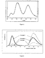
- the curves of the figure 1 give, for the compounds thus obtained, the emission spectrum for an excitation wavelength of 370 nm. It can thus be seen that in response to excitation in the UV range, the compounds emit in the red (peak around 625 nm) and also in the blue (peak around 440 nm).
- the excitation spectrum of the compound of Example 1, for the emission wavelength 623 nm, is represented in FIG. figure 2 . It appears from this figure that the maximum efficiency is reached for a wavelength of 350 nm. Between 350nm and 400nm the relative yield varies between 100% and 78%.
- a mixture of the phosphor of Example 1 is formed with the compound of formula (Sr 0.95 Eu 0.05 ) Ga 2.1 S 4 obtained in the manner described in Example 1 of WO 02/100976 , in different mass proportions.
- This example relates to a luminophore usable for the second embodiment of the invention.
- Example 1 The compound prepared is identical to that of Example 1 for its formulation.
- the procedure is as described in Example 1 starting from the same starting materials and in the same quantities. However, these products are simply mixed and deagglomerated without being ground.
- the figure 3 gives, for the compound thus obtained, the emission spectrum for an excitation wavelength of 370 nm. So we see that in response to excitation in the UV field, the compound emits in the red (peak around 625 nm), in the blue (peak around 440 nm) and also in the green (peak around 510 nm).
- Example 1 To prepare the products, the procedure is as in Example 1 by mixing the starting materials and grinding for 30 minutes. A first heat treatment is carried out at 950 ° C for 2 hours in air. Mixing in 30 minutes the product obtained by calcination with 1% by weight of NH 4 Cl. The mixture is then heated for 4 hours at 1200 ° C in a reducing atmosphere composed of an Ar / H 2 5% H 2 . At the end of the treatment, the product is crushed slightly.
- the curves of the figure 4 give, for the compounds thus obtained, the emission spectrum for an excitation wavelength of 370 nm. It can be seen that the compound of Example 5 has intensities for the blue and the red. substantially similar emissions. On the other hand, the red color is maximized for the compound of Example 6
Description
- La présente invention concerne une diode électroluminescente émettant une lumière blanche.
- Les diodes électroluminescentes (DEL) sont des produits en plein développement actuellement. On cherche tout particulièrement à obtenir des DEL émettant dans le blanc. Il est nécessaire pour cela et pour avoir un bon rendu de couleur de mettre en oeuvre dans la fabrication de telles DEL une combinaison d'au moins trois luminophores émettant chacun dans une couleur d'émission primaire. Or, il est souhaitable d'utiliser le minimum possible de luminophores afin de faciliter la fabrication de ces DEL et/ou d'améliorer leurs propriétés.
-
US 5194332 décrit des luminophores dopés à l'europium de formule générale BaMg2Si2O7 qui sont recuits en présence d'un flux. Ces luminophores sont utilisés en fait dans des lampes fluorescentes. - La présente invention répond à ce besoin.
- Dans ce but, la diode électroluminescente selon l'invention, qui émet une lumière blanche, est caractérisée en ce qu'elle comprend:
- une source d'émission d'une radiation dans la gamme de longueur d'onde comprise entre 370 nm et 420 nm;
- un premier luminophore émettant une lumière bleue et une lumière rouge, de formule :
Bci3(1-x)Eu3xMg1-yMnySi2O8 (1)
dans laquelle 0 < x ≤ 0,3 et 0 < y ≤ 0,3; - un second luminophore émettant une lumière verte.
- Selon un autre mode de réalisation de l'invention, la diode émettant dans le blanc est caractérisée en ce qu'elle comprend :
- une source d'émission d'une radiation dans la gamme de longueur d'onde comprise entre 370 nm et 420 nm;
- un luminophore de composition chimique suivante :
Ba3(1-x)Eu3xMg1-yMnySi2O8
avec 0 < x ≤ 0,3 et 0 < y ≤ 0,3;
ce luminophore se présentant sous la forme d'un mélange d'au moins des phases Ba2SiO4, Ba2MgSi2O7 et Ba3MgSi2O8. - Les DEL selon les différents modes de réalisation de l'invention ont l'avantage de ne comprendre qu'un nombre réduit de luminophores.
- D'autres caractéristiques, détails et avantages de l'invention apparaîtront encore plus complètement à la lecture de la description qui va suivre et du dessin annexé dans lequel :
- la
figure 1 est un graphe qui représente les spectres d'émission de deux luminophores selon l'invention pour une longueur d'onde d'excitation de 370 nm; - la
figure 2 est un graphe qui représente le spectre d'excitation d'un luminophore selon l'invention pour une longueur d'onde d'émission de 623 nm; - la
figure 3 est un graphe qui représente le spectre d'émision d'un luminophore selon l'invention pour une longueur d'onde d'excitation de 370 nm; - la
figure 4 est un graphe qui représente les spectres d'émission de trois luminophores selon l'invention pour une longueur d'onde d'excitation de 370 nm. - Par terre rare on entend les éléments du groupe constitué par le scandium, l'yttrium et les éléments de la classification périodique de numéro atomique compris inclusivement entre 57 et 71.
- On précise pour la suite de la description que, sauf indication contraire, dans les fourchettes de valeurs qui sont données, les valeurs aux bornes sont incluses.
- Dans le cas du premier mode de réalisation de l'invention, la DEL comprend trois éléments essentiels qui sont une source d'émission et deux luminophores.
- Plus précisément, la source d'émission est une source capable d'émettre une radiation dont la longueur d'onde est comprise dans la gamme de 370 nm environ à 420 nm environ. Il s'agit en fait d'une radiation dans la gamme de l'ultra-violet proche visible. De telles sources sont bien connues dans la technique, ce peut être par exemple des semi-conducteurs du type InGaN, GaN ou AIGaN.
- D'une manière connue en soi, cette source est munie de connections électriques pour être reliée à un circuit électrique. La radiation émise par la source va servir à exciter les luminophores de la DEL de l'invention.
- Dans le cas du premier mode de réalisation, la DEL comprend un premier luminophore qui est capable d'émettre à la fois une lumière bleue et une lumière rouge. Ce luminophore répond à la formule (1) qui a été donnée plus haut.
- Ce luminophore est un silicate de baryum et de magnésium, dopé avec de l'europium, qui peut être considéré en substitution partielle du baryum, et avec du manganèse, qui peut être considéré en substitution partielle du magnésium.
- Lorsqu'il est soumis à une excitation UV, c'est à dire à un rayonnement dans une gamme de longueur d'onde comprise entre environ 370 nm et environ 420 nm, ce produit a pour propriété d'émettre notamment dans le rouge et aussi dans le bleu, c'est à dire dans une gamme de longueurs d'onde comprises entre 400 nm et 500 nm pour le bleu et entre 550 nm et 720 nm, plus particulièrement entre 550 nm et 700 nm, pour le rouge avec un bon rendement.
- Plus particulièrement, le luminophore répond à la formule (1) précitée dans laquelle 0,0001 ≤ x ≤ 0,25 et 0,0001 ≤ y ≤ 0,25.
- Encore plus particulièrement, le luminophore répond à la formule (1) précitée dans laquelle 0,01 ≤ x ≤ 0,25 et 0,01 ≤ y ≤ 0,25.
- On peut noter qu'il est avantageux d'avoir une concentration en europium dans le composé d'au moins 0,01% pour obtenir une émission de meilleure intensité. Il est aussi avantageux d'avoir une concentration en europium et en manganèse d'au plus 25% afin de limiter au maximum des phénomènes d'auto-extinction gênants. Les pourcentages indiqués ci-dessus correspondent aux taux de substitution en mole des ions dopants Eu2+ et Mn2 respectivement aux ions Ba2+ et Mg2+.
- Selon une autre variante, le luminophore de formule (1) vérifie les valeurs de x et y suivantes : 0,01 ≤ x ≤ 0,03 et 0,04 ≤ y ≤ 0,06. Pour ces valeurs de x et de y l'intensité d'émission est la plus importante.
- Selon encore une autre variante, le luminophore de formule (1) vérifie les valeurs de x et y suivantes : 0,01 ≤ x ≤ 0,02 et 0,05 ≤ y ≤ 0,1. Dans ce cas, les luminophores présentent pour chacune des couleurs bleu et rouge des intensités d'émission sensiblement identiques entre elles.
- Selon une dernière variante, le luminophore de formule (1) vérifie les valeurs de x et y suivantes : 0,09 ≤ x ≤ 0,11 et 0,09 ≤ y ≤ 0,11. Dans ce cas, les luminophores présentent une intensité d'émission élevée pour la couleur rouge.
- Enfin, dans le composé de formule (1), le baryum, le magnésium et le silicium peuvent être partiellement substitués par d'autres éléments que ceux qui ont été décrits plus haut. Ainsi, le baryum peut être partiellement substitué par du calcium et/ou du strontium dans une proportion qui peut aller jusqu'à environ 30%, cette proportion étant exprimée par le rapport atomique substituant/(susbtituant+baryum). Le magnésium peut être partiellement substitué par du zinc dans une proportion qui peut aller jusqu'à environ 30%, cette proportion étant aussi exprimée par le rapport atomique Zn/(Zn+Mg). Enfin, le silicium peut être partiellement substitué par du germanium, de l'aluminium et/ou du phosphore dans une proportion qui peut aller jusqu'à environ 10%, cette proportion étant exprimée par le rapport atomique substituant/(susbtituant+silicium).
- Enfin, ce premier luminophore se présente sous une forme phasiquement pure. Le diagramme RX de ce produit ne fait apparaître en effet qu'une phase correspondant à la phase Ba3MgSi2O8.
- Le second luminophore de la DEL selon le premier mode de réalisation est un luminophore émettant une lumière verte. On entend par là une lumière dont la longueur d'onde est comprise entre environ 500 nm et environ 550 nm. Ce luminophore est capable d'émettre cette lumière lorsqu'il est soumis à la radiation émise par la source précitée.
- Il existe plusieurs produit connus susceptibles d'être utilisés comme second luminophore de ce type pour la DEL selon l'invention.
- Ainsi, ce second luminophore peut être choisi parmi les familles de produits ci-dessous :
- les sulfures de zinc ZnS dopés au cuivre ou dopés au cuivre et à l'aluminium;
- les silicates d'alcalino-terreux dopés à l'europium; on entend par là les produits du type MSi2O5 : Eu2+ ou M2SiO4: Eu2+, M étant un alcalino-terreux comme le baryum ou le strontium;
- les aluminates d'alcalino-terreux dopés à l'europium ou à l'europium en combinaison avec le manganèse comme les produits du type MAl2O4: Eu2+, M étant un alcalino-terreux comme le strontium, M4Al14O25 : Eu2+, M étant un alcalino-terreux comme le strontium ou encore du type M0,82Al12O18,82 : Eu2+ ou M0,82Al12O18,82 Eu2+ Mn2+, M étant un alcalino-terreux comme le baryum;
- les borates de terre rare dopés au cérium et au terbium comme par exemple les produits de formule MBO3 : (Ce3+, Tb3+), M étant au moins une terre rare comme Sc, Gd, Lu éventuellement combinée avec l'yttrium;
- les thiogallates, thioaluminates ou thioindates de zinc, de magnésium ou d'alcalino-terreux dopés à l'europium et/ou au manganèse ou encore dopés au cérium et au terbium; il peut s'agir ici de produits du type MN2S4 : dopants, M désignant au moins le zinc, le magnésium ou un alcalino-terreux comme par exemple Ca, Sr, Ba et N désignant au moins Al, Ga et In;
- les phosphates ou borophosphates d'alcafino-terreux dopés à l'europium ou dopés à l'europium et au terbium; on peut citer ici les produits de formule M2P2O7: Eu2+, Tb3+) ou de formule M6BP5O20 : Eu2+, formules dans lesquelles M est un alcalino-terreux comme le strontium par exemple;
- les silicates de terre rare dopés à l'europium et au terbium, comme les produits de formule M2SiO5. (Ce3+, Tb3+), M étant au moins une terre rare comme Y, Gd et Lu;
- les silicates d'yttrium et d'azote dopés à l'europium comme Y5(SiO4)3N : Ce3+;
- les aluminates de magnésium et d'alcalino-terreux dopés à l'europium en combinaison avec le cérium et le terbium ou en combinaison avec du manganèse; on peut mentionner les produits du type MMgAl10O17 : dopant, M étant au moins un alcalino-terreux, par exemple une combinaison Ba, Sr;
- les chlorosilicates de magnésium et d'alcalino-terreux dopés à l'europium éventuellement en combinaison avec du manganèse, notamment un produit du type M8Mg(SiO4)Cl2 : dopant(s), M étant un alcalino-terreux, par exemple le calcium.
- D'une manière connue en soi, les produits mentionnés comme dopants dans les produits qui viennent d'être cités ci-dessus sont utilisés en combinaison avec la matrice pour lui donner les propriétés requises de luminescence.
- Comme second luminophore préféré dans le cadre de la présente invention, on peut utiliser Ba2SiO4 dopé à l'europium, SrGa2S4 dopé à l'europium, le sulfure de zinc dopé au cuivre ou dopé au cuivre et à l'aluminium et SrAl2O4 dopé à l'europium.
- On peut aussi utiliser à titre de second luminophore un composé à base d'au moins un élément A choisi parmi les alcalino-terreux, d'au moins un élément B choisi parmi l'aluminium, le gallium ou l'indium, de soufre et d'un dopant susceptible de conférer des propriétés de luminescence audit composé et qui se présente sous la forme d'un mélange d'une phase cristallographique majoritaire de type AB2S4 et d'une phase cristallographique de type B2S3. Un tel composé est décrit dans la demande de brevet
WO 02/100976 - Le luminophore de formule (1) utilisé pour l'invention se prépare généralement par une réaction à l'état solide à haute température.
- Comme produit de départ, on peut utiliser directement les oxydes des métaux requis ou des composés organiques ou minéraux susceptibles de former ces oxydes par chauffage comme les carbonates, oxalates, hydroxydes, acétates, nitrates, borates desdits métaux.
- On forme un mélange intime, notamment par broyage, aux concentrations appropriées de tous les produits de départ à l'état finement divisé.
- On peut également envisager de préparer un mélange de départ par co-précipitation à partir de solutions des précurseurs des oxydes désirés, par exemple en milieu aqueux.
- Le mélange des produits de départ est ensuite chauffé au moins une fois pendant une période comprise entre une heure et une centaine d'heures environ, à une température située entre environ 500°C et environ 1300°C; il est préférable d'effectuer le chauffage en présence d'un flux, par exemple du type NH4Cl, et au moins en partie sous une atmosphère réductrice (hydrogène dans l'argon par exemple) pour porter totalement l'europium à l'état divalent.
- Le second mode de réalisation de l'invention va maintenant être décrit.
- La différence avec le premier mode est que la diode ne comprend plus qu'un seul luminophore. Il s'agit d'un produit qui répond à la composition chimique donnée plus haut. Cette composition correspond à la formule (1) donnée précédemment avec les valeurs précitées de x et de y. Toutes les valeurs plus particulières de x et de y qui ont été mentionnées plus haut ainsi que ce qui a été dit pour les possibles substitutions partielles du baryum, du magnésium et du silicium s'appliquent aussi ici pour ce luminophore. Mais, à la différence du luminophore du premier mode qui est phasiquement pur, celui-ci se présente sous la forme d'un mélange d'au moins trois phases. Il s'agit d'au moins des phases Ba2SiO4, Ba2MgSi2O7 et Ba3MgSi2O8. Une phase supplémentaire du type BaCO3 peut éventuellement être présente. L'existence de ces phases est mise en évidence par l'analyse RX et les diagrammes qui en résultent.
- Lorsqu'il est soumis à une excitation UV du même type qu'indiqué plus haut (comprise entre environ 370 nm et environ 420 nm), ce produit émet dans le rouge et dans le bleu mais aussi dans le vert (émission entre 500 nm et 550 nm). De ce fait, dans le cas de ce second mode de réalisation, la DEL de l'invention qui émet dans le blanc ne comprend toutefois qu'un luminophore unique.
- Le luminophore du second mode de réalisation peut aussi être préparé par réaction solide/solide à haute température à partir des oxydes des métaux requis ou des composés organiques ou minéraux susceptibles de former ces oxydes par chauffage comme les carbonates, oxalates, hydroxydes, acétates, nitrates, borates desdits métaux.
- On forme dans ce cas un mélange homogène aux concentrations appropriées de tous les produits de départ. Ce mélange se fait par simple désagglomération des poudres des produits de départ sans mettre en oeuvre un broyage. On procède ensuite à une calcination. Cette calcination peut se faire sans flux. Elle est réalisée de préférence au moins en partie sous une atmosphère réductrice (hydrogène dans l'argon par exemple) pour la raison donnée plus haut et à une température qui est d'environ au moins 500°C et d'au plus 1150°C de préférence.
- Dans les deux modes de réalisations décrits il est préférable d'utiliser des luminophores dont les tailles sont d'au plus 20 µm et de préférence d'au plus 10µm et dont la taille moyenne peut être par exemple comprise entre 3 µm et 6 µm. Ces valeurs de taille sont celles déterminées par la technique de diffraction laser et en utilisant un granulomètre du type COULTER (associé à une sonde à ultrason de 450 W).
- Dans les deux modes de réalisations décrits et d'une manière connue pour la fabrication d'une DEL, le ou les luminophores sont incorporés dans une matrice polymère, du type époxy par exemple, dans laquelle est insérée la source d'émission de radiation précitée, l'ensemble étant placé dans un boîtier.
- Dans le cas du premier mode de réalisation, la colorimétrie blanche de la lumière émise par la DEL dépend de la nature des deux luminophores et de leurs proportions respectives. De manière connue, ces proportions peuvent être définies à partir de la détermination des rendements quantiques relatifs de chacun des luminophores.
- L'invention concerne enfin un dispositif d'éclairage qui est caractérisé en ce qu'il comprend une diode du type décrit ci-dessus. De tels dispositifs, comme les lampes, sont bien connus et sont constitués par exemple d'une ou de plusieurs DEL, insérées par couches, dans des boîtiers dont une surface est transparente.
- Des exemples vont maintenant être donnés.
- Cet exemple concerne un luminophore utilisable pour le premier mode de réalisation de l'invention et répondant à la composition Ba3MgSi2O8: 2% Eu2+, 5% Mn2+ et correspondant à la formule Ba2,94Eu0,06Mg0,95Mn0,05Si2O8 (les pourcentages indiqués pour les ions dopants correspondent aux taux de substitution en mole des ions Eu2+ et Mn2+ respectivement aux ions Ba2+ et Mg2+). On procède par voie solide en mélangeant les oxydes BaCO3, Eu2O3, (MgCO3)4Mg(OH)2.5H2O, MnCO3 et SiO2 dans des proportions stoechiométriques. 0,4 mole de NH4Cl est ajoutée au mélange en tant que flux.
Produits de départ Quantités mises en oeuvre BaCO3 1,8629 g Eu2O3 0,0339 g (MgCO3)4Mg(OH)2.5H2O 0,2963 g MnCO3 0,0185 g SiO2 0,3858 g NH4Cl 0,0687 g - Ces produits de départ sont mélangés de façon homogène par broyage; le mélange, placé dans un creuset, est introduit dans un four où il subit deux traitements thermiques. Un premier traitement thermique est effectué à 600 °C pendant 4 heures à l'air. Le mélange, de couleur grise, est alors broyé puis replacé au four dans un creuset en alumine. Après une purge de 4 heures du four avec un mélange Ar/H2 10 %, le mélange est chauffé 4 heures à 1200 °C dans cette atmosphère réductrice. Une rampe de montée et de descente en température de 360 °C/h est employée. Le produit obtenu se présente sous la forme d'une poudre blanche.
- Cet exemple concerne un luminophore utilisable pour le premier mode de réalisation de l'invention et répondant à la composition Ba3MgSi2O8: 2% Eu2+, 20% Mn2+ et correspondant à la formule Ba2,94Eu0,06Mg0,8Mn0,2Si2O8. On procède comme dans l'exemple 1, par voie solide, en mélangeant les oxydes BaCO3, Eu2O3, (MgCO3)4Mg(OH)2.5H2O, MnCO3 et SiO2 dans des proportions stoechiométriques, 0,4 mole de NH4Cl est ajoutée au mélange en tant que flux.
Produits de départ Quantités mises en oeuvre BaCO3 1,8629 g Eu2O3 0,0339 g (MgCO3)4Mg(OH)2.5H2 0,2492 g MnCO3 0,0740 g SiO2 0,3858 g NH4Cl 0,0687 g - Le mode opératoire est ensuite identique à celui de l'exemple 1.
- Les courbes de la
figure 1 donnent, pour les composés ainsi obtenus, le spectre d'émission pour une longueur d'onde d'excitation de 370 nm. On voit donc qu'en réponse à une excitation dans le domaine des UV, les composés émettent dans le rouge (pic vers 625nm) et aussi dans le bleu (pic vers 440nm). - Le spectre d'excitation du composé de l'exemple 1, pour la longueur d'onde d'émission 623 nm, est représenté à la
figure 2 . Il apparaît de cette figure que le rendement maximum est atteint pour une longueur d'onde de 350nm. Entre 350nm et 400nm le rendement relatif varie entre 100% et 78%. - On forme un mélange du luminophore de l'exemple 1 avec le composé de formule (Sr0,95Eu0,05)Ga2,1S4 obtenu de la manière décrite dans l'exemple 1 de
WO 02/100976 Luminophore ex.1 60% 70% (Sr0,95EU0,05)Ga2,1S4 40% 30% Coordonnées trichromatiques x = 0,341 x = 0,352 y = 0,374 y = 0,325 - Cet exemple concerne un luminophore utilisable pour le second mode de réalisation de l'invention.
- Le composé préparé est identique à celui de l'exemple 1 pour sa formulation. On procède comme décrit dans l'exemple 1 en partant des mêmes produits de départ et dans les mêmes quantités. Toutefois, ces produits sont simplement mélangés et désaglomérés sans être broyés.
- On procède ensuite à la calcination comme dans l'exemple 1.
- La
figure 3 donne, pour le composés ainsi obtenu, le spectre d'émission pour une longueur d'onde d'excitation de 370 nm. On voit donc qu'en réponse à une excitation dans le domaine des UV, le composé émette dans le rouge (pic vers 625 nm), dans le bleu (pic vers 440 nm) et aussi dans le vert (pic vers 510 nm). - Les coordonnées trichromatiques du composé sont calculées à partir du spectre d'émission de la
figure 3 et selon la norme précitée. Ces coordonnées sont x = 0,36 et y = 0,4. - Ces exemples concernent des luminophores utilisables pour le premier mode de réalisation de l'invention.
- Pour préparer les produits, on procède comme dans l'exemple 1 en mélangeant les produits de départ et en broyant pendant 30 minutes. Un premier traitement thermique est effectué à 950°C pendant 2 heures à l'air. On mélange en 30 minutes le produit issu de la calcination avec 1% en poids de NH4Cl. Le mélange est chauffé ensuite 4 heures à 1200 °C dans une atmosphère réductrice constituée par un mélange Ar/H2 à 5 % en H2. A l'issue du traitement on broie légèrement le produit.
- On donne ci-dessous dans le tableau 1 les quantités utilisées des produits de départ (en g.) et dans le tableau 2 les formules des luminophores obtenus.
Tableau 1 Exemple BaCO3 Mg(OH)2, 4MgCO3,5H2O SiO2 Eu2O3 MnCO3 5 18,771 2,769 3,932 0,338 0,395 6 17,142 2,754 3,910 1,681 0,393 7 17,059 2,436 3,891 1,673 0,782 Tableau 2 Exemple 5 Ba2,94EU0,06Mg0,9Mn0,1Si2O8 6 Ba2,70Eu0,30Mg0,9Mn0,1Si2O8 7 Ba2,70Eu0,30Mg0,8Mn0,2Si2O8 - Les courbes de la
figure 4 donnent, pour les composés ainsi obtenus, le spectre d'émission pour une longueur d'onde d'excitation de 370 nm. On voit que le composé de l'exemple 5 présente pour le bleu et le rouge des intensités d'émission sensiblement analogues. La couleur rouge est par contre maximisée pour le composé de l'exemple 6
Claims (12)
- Diode électroluminescente émettant une lumière blanche, caractérisée en ce qu'elle comprend :- une source d'émission d'une radiation dans la gamme de longueur d'onde comprise entre 370 nm et 420 nm;- un premier luminophore émettant une lumière bleue et une lumière rouge, de formule :
Ba3(1-x)Eu3xMg1-yMnySi2O8 (1)
dans laquelle 0 < x ≤ 0,3 et 0 < y ≤ 0,3;- un second luminophore émettant une lumière verte. - Diode selon la revendication 1, caractérisée en ce qu'elle comprend à titre de second luminophore un luminophore choisi parmi :- un sulfure de zinc dopé au cuivre ou dopé au cuivre et à l'aluminium;- un silicate d'alcalino-terreux dopé à l'europium;- un aluminate d'alcalino-terreux dopé à l'europium;- un borate de terre rare dopé au cérium et au terbium;- un thiogallate, thioaluminate ou thioindate de zinc, de magnésium ou d'alcalino-terreux dopé à l'europium et/ou au manganèse;- un phosphate ou borophosphate d'alcalino-terreux dopé à l'europium ou dopé à l'europium et au terbium;- un silicate de terre rare dopé à l'europium et au terbium;- un silicate d'yttrium et d'azote dopé à l'europium;- un aluminate de magnésium et d'alcalino-terreux dopé à l'europium en combinaison avec le cérium et le terbium ou en combinaison avec du manganèse;- un chlorosilicate de magnésium et d'alcalino-terreux dopé à l'europium éventuellement en combinaison avec du manganèse.
- Diode selon la revendication 1, caractérisée en ce qu'elle comprend à titre de second luminophore un luminophore choisi parmi Ba2SiO4 dopé à l'europium, SrGa2S4 dopé à l'europium, le sulfure de zinc dopé au cuivre ou dopé au cuivre et à l'aluminium et SrAl2O4 dopé à l'europium, et un composé à base d'au moins un élément A choisi parmi les alcalino-terreux, d'au moins un élément B choisi parmi l'aluminium, le gallium ou l'indium, de soufre et d'un dopant susceptible de conférer des propriétés de luminescence audit composé et qui se présente sous la forme d'un mélange d'une phase cristallographique majoritaire de type AB2S4 et d'une phase cristallographique de type B2S3.
- Diode électroluminescente émettant une lumière blanche, caractérisée en ce qu'elle comprend :- une source d'émission d'une radiation dans la gamme de longueur d'onde comprise entre 370 nm et 420 nm;- un luminophore de composition chimique suivante:
Ba3(1-x)Eu3xMg1-yMnySi2O8
avec 0 < x ≤ 0,3 et 0 < y ≤ 0,3;
ce luminophore se présentant sous la forme d'un mélange d'au moins des phases Ba2SiO4, Ba2MgSi2O7 et Ba3MgSi2O8. - Diode selon l'une des revendications précédentes, caractérisée en ce qu'elle comprend un luminophore de formule (1) ou de composition chimique précitée dans laquelle 0,0001 ≤ x ≤ 0,25 et 0,0001 ≤ y ≤ 0,25.
- Diode selon la revendication 5, caractérisée en ce qu'elle comprend un luminophore de formule (1) ou de composition chimique précitée dans laquelle 0,01 ≤ x ≤ 0,25 et 0,01 ≤ y ≤ 0,25.
- Diode selon la revendication 6, caractérisée en ce qu'elle comprend un luminophore de formule (1) ou de composition chimique précitée dans laquelle 0,01 ≤ x ≤ 0,03 et 0,04 ≤ y ≤ 0,06.
- Diode selon la revendication 6, caractérisée en ce qu'elle comprend un luminophore de formule (1) ou de composition chimique précitée dans laquelle 0,01 ≤ x ≤ 0,02 et 0,05 ≤ y ≤ 0,1.
- Diode selon la revendication 6, caractérisée en ce qu'elle comprend un luminophore de formule (1) ou de composition chimique précitée dans laquelle 0,09 ≤ x ≤ 0,11 et 0,09 ≤ y ≤ 0,11.
- Diode selon l'une des revendications 1 à 3, caractérisée en ce qu'elle comprend un luminophore de formule (1) dans laquelle x = 0,1 et y = 0,1 ou dans laquelle x = 0,1 et y = 0,2.
- Diode selon l'une des revendications précédentes, caractérisée en ce qu'elle comprend un luminophore de formule (1) dans laquelle le baryum, le magnésium et le silicium ne sont pas substitués par d'autres éléments que l'europium et le manganèse.
- Dispositif d'éclairage, caractérisé en ce qu'il comprend une diode selon l'une des revendications précédentes.
Priority Applications (1)
| Application Number | Priority Date | Filing Date | Title |
|---|---|---|---|
| PL05753855T PL1735404T3 (pl) | 2004-04-16 | 2005-04-06 | Dioda elektroluminescencyjna emitująca światło białe |
Applications Claiming Priority (2)
| Application Number | Priority Date | Filing Date | Title |
|---|---|---|---|
| FR0404045A FR2869159B1 (fr) | 2004-04-16 | 2004-04-16 | Diode electroluminescente emettant une lumiere blanche |
| PCT/FR2005/000841 WO2005112135A2 (fr) | 2004-04-16 | 2005-04-06 | Diode electroluminescente emettant une lumiere blanche |
Publications (2)
| Publication Number | Publication Date |
|---|---|
| EP1735404A2 EP1735404A2 (fr) | 2006-12-27 |
| EP1735404B1 true EP1735404B1 (fr) | 2010-08-11 |
Family
ID=34944943
Family Applications (1)
| Application Number | Title | Priority Date | Filing Date |
|---|---|---|---|
| EP05753855A Not-in-force EP1735404B1 (fr) | 2004-04-16 | 2005-04-06 | Diode electroluminescente emettant une lumiere blanche |
Country Status (13)
| Country | Link |
|---|---|
| US (1) | US7968005B2 (fr) |
| EP (1) | EP1735404B1 (fr) |
| JP (1) | JP4799549B2 (fr) |
| KR (1) | KR100864124B1 (fr) |
| CN (2) | CN101864299B (fr) |
| AT (1) | ATE477316T1 (fr) |
| CA (1) | CA2560470C (fr) |
| DE (1) | DE602005022846D1 (fr) |
| FR (1) | FR2869159B1 (fr) |
| MX (1) | MXPA06011944A (fr) |
| PL (1) | PL1735404T3 (fr) |
| TW (1) | TWI481061B (fr) |
| WO (1) | WO2005112135A2 (fr) |
Families Citing this family (20)
| Publication number | Priority date | Publication date | Assignee | Title |
|---|---|---|---|---|
| FR2846663B1 (fr) * | 2002-11-05 | 2006-08-11 | Rhodia Elect & Catalysis | Materiau transformant la lumiere, notamment pour parois de serres, comprenant comme additif un silicate de baryum et de magnesium |
| JP4949793B2 (ja) * | 2006-09-29 | 2012-06-13 | 京セラ株式会社 | 蛍光体及び波長変換器ならびに発光装置 |
| JP5137850B2 (ja) * | 2006-12-25 | 2013-02-06 | 京セラ株式会社 | 蛍光体およびそれを用いた波長変換器、発光装置、照明装置 |
| JP5216993B2 (ja) * | 2006-12-27 | 2013-06-19 | 国立大学法人九州工業大学 | 蛍光体及びランプ |
| JP4991362B2 (ja) * | 2007-01-29 | 2012-08-01 | 京セラ株式会社 | 蛍光体とその製造方法および波長変換器ならびに発光装置 |
| JP5004616B2 (ja) * | 2007-02-26 | 2012-08-22 | 京セラ株式会社 | 蛍光体とその製造方法および波長変換器ならびに発光装置 |
| JP5036454B2 (ja) * | 2007-08-29 | 2012-09-26 | 京セラ株式会社 | 蛍光体粒子および波長変換器ならびに発光装置 |
| TW200925247A (en) * | 2007-12-12 | 2009-06-16 | Wang yong qi | Three spectral band phosphor powder for using in multilayered agricultural film |
| RU2503880C2 (ru) * | 2008-02-21 | 2014-01-10 | Конинклейке Филипс Электроникс Н.В. | Светодиодный (сид) источник света, подобный gls |
| JP2009280793A (ja) * | 2008-04-24 | 2009-12-03 | Kyocera Corp | 蛍光体および波長変換器ならびに発光装置、照明装置 |
| WO2011004961A2 (fr) * | 2009-06-24 | 2011-01-13 | Seoul Semiconductor Co., Ltd. | Dispositif électroluminescent employant des substances luminescentes dotées de luminophores doxyorthosilicate |
| WO2011022392A1 (fr) * | 2009-08-17 | 2011-02-24 | Osram Sylvania Inc. | Mélange de phosphores pour source de lumière del et source de lumière del le contenant |
| JP5633845B2 (ja) * | 2009-11-30 | 2014-12-03 | 独立行政法人産業技術総合研究所 | フォトクロミック物質及びその製造方法 |
| US20120153184A1 (en) * | 2010-12-21 | 2012-06-21 | Honeywell International Inc. | Luminescent phosphor-containing materials, and methods for their production and use in authenticating articles |
| JP5689407B2 (ja) * | 2011-12-28 | 2015-03-25 | 宇部マテリアルズ株式会社 | ケイ酸塩緑色発光蛍光体 |
| CN102585823A (zh) * | 2012-01-31 | 2012-07-18 | 厦门大学 | 一种紫外led激发三基色氮氧化物荧光粉及其合成方法 |
| US8679367B2 (en) * | 2012-08-09 | 2014-03-25 | Intematix Corporation | Green-emitting (oxy)nitride-based phosphors and light-emitting device using the same |
| JP2017501264A (ja) * | 2013-12-04 | 2017-01-12 | メルク パテント ゲゼルシャフト ミット ベシュレンクテル ハフツングMerck Patent Gesellschaft mit beschraenkter Haftung | Eu2+活性化蛍光体 |
| JP6681351B2 (ja) * | 2014-06-30 | 2020-04-15 | ローディア オペレーションズ | ケイ酸マグネシウムの懸濁液、その製造方法および蛍光体としてのその使用 |
| JP5799434B2 (ja) * | 2014-08-27 | 2015-10-28 | 独立行政法人 国立印刷局 | 残光性発光体とその作製方法、残光性発光インキ組成物及び真偽判別印刷物 |
Family Cites Families (19)
| Publication number | Priority date | Publication date | Assignee | Title |
|---|---|---|---|---|
| GB829546A (en) * | 1955-04-04 | 1960-03-02 | British Thomson Houston Co Ltd | Luminescent material |
| US3544482A (en) * | 1968-03-15 | 1970-12-01 | Sylvania Electric Prod | Europium and manganese activated alkaline earth silicate phosphors |
| DE10028266A1 (de) * | 2000-06-09 | 2001-12-13 | Patent Treuhand Ges Fuer Elektrische Gluehlampen Mbh | Hocheffizienter Leuchtstoff |
| US5194332A (en) * | 1989-07-31 | 1993-03-16 | Gte Products Corporation | Europium-activated barium magnesium silicate phosphor |
| US5839718A (en) * | 1997-07-22 | 1998-11-24 | Usr Optonix Inc. | Long persistent phosphorescence phosphor |
| JP2000003837A (ja) * | 1998-06-12 | 2000-01-07 | Nippon Chemicon Corp | 電解コンデンサ |
| JP2000017257A (ja) * | 1998-06-30 | 2000-01-18 | Nichia Chem Ind Ltd | 蛍光体及びそれを用いた発光スクリーン |
| US6429583B1 (en) * | 1998-11-30 | 2002-08-06 | General Electric Company | Light emitting device with ba2mgsi2o7:eu2+, ba2sio4:eu2+, or (srxcay ba1-x-y)(a1zga1-z)2sr:eu2+phosphors |
| JP3679695B2 (ja) | 1999-08-12 | 2005-08-03 | 東京エレクトロン株式会社 | 現像装置、基板処理装置及び現像方法 |
| JP3515737B2 (ja) * | 2000-06-22 | 2004-04-05 | 松下電器産業株式会社 | 蛍光体およびそれを用いた蛍光ランプ |
| DE10036940A1 (de) * | 2000-07-28 | 2002-02-07 | Patent Treuhand Ges Fuer Elektrische Gluehlampen Mbh | Lumineszenz-Konversions-LED |
| JP4077170B2 (ja) * | 2000-09-21 | 2008-04-16 | シャープ株式会社 | 半導体発光装置 |
| US6802990B2 (en) * | 2000-09-29 | 2004-10-12 | Sumitomo Chemical Company, Limited | Fluorescent substances for vacuum ultraviolet radiation excited light-emitting devices |
| AT410266B (de) * | 2000-12-28 | 2003-03-25 | Tridonic Optoelectronics Gmbh | Lichtquelle mit einem lichtemittierenden element |
| WO2003032407A1 (fr) * | 2001-10-01 | 2003-04-17 | Matsushita Electric Industrial Co.,Ltd. | Element electroluminescent semi-conducteur et dispositif electroluminescent utilisant un tel element |
| JP3985486B2 (ja) * | 2001-10-01 | 2007-10-03 | 松下電器産業株式会社 | 半導体発光素子とこれを用いた発光装置 |
| TW573370B (en) * | 2002-08-19 | 2004-01-21 | Solidlite Corp | Tri-color ZnSe white LED |
| WO2005004202A2 (fr) | 2003-06-24 | 2005-01-13 | Gelcore Llc | Melanges de phosphore en spectre continu de generation de lumiere blanche a l'aide de puces a diodes electroluminescentes |
| US7026755B2 (en) * | 2003-08-07 | 2006-04-11 | General Electric Company | Deep red phosphor for general illumination applications |
-
2004
- 2004-04-16 FR FR0404045A patent/FR2869159B1/fr not_active Expired - Fee Related
-
2005
- 2005-04-06 DE DE602005022846T patent/DE602005022846D1/de active Active
- 2005-04-06 WO PCT/FR2005/000841 patent/WO2005112135A2/fr active Application Filing
- 2005-04-06 AT AT05753855T patent/ATE477316T1/de not_active IP Right Cessation
- 2005-04-06 KR KR1020067021263A patent/KR100864124B1/ko not_active IP Right Cessation
- 2005-04-06 JP JP2007507812A patent/JP4799549B2/ja not_active Expired - Fee Related
- 2005-04-06 CA CA002560470A patent/CA2560470C/fr not_active Expired - Fee Related
- 2005-04-06 EP EP05753855A patent/EP1735404B1/fr not_active Not-in-force
- 2005-04-06 US US11/547,154 patent/US7968005B2/en not_active Expired - Fee Related
- 2005-04-06 CN CN201010208223.9A patent/CN101864299B/zh not_active Expired - Fee Related
- 2005-04-06 PL PL05753855T patent/PL1735404T3/pl unknown
- 2005-04-06 MX MXPA06011944A patent/MXPA06011944A/es active IP Right Grant
- 2005-04-06 CN CN200580011468XA patent/CN1942553B/zh not_active Expired - Fee Related
- 2005-04-15 TW TW094112145A patent/TWI481061B/zh not_active IP Right Cessation
Also Published As
| Publication number | Publication date |
|---|---|
| CA2560470C (fr) | 2009-12-22 |
| KR20070013282A (ko) | 2007-01-30 |
| CN1942553B (zh) | 2013-05-29 |
| CN101864299B (zh) | 2015-01-14 |
| TW200605396A (en) | 2006-02-01 |
| WO2005112135A2 (fr) | 2005-11-24 |
| FR2869159B1 (fr) | 2006-06-16 |
| ATE477316T1 (de) | 2010-08-15 |
| EP1735404A2 (fr) | 2006-12-27 |
| TWI481061B (zh) | 2015-04-11 |
| DE602005022846D1 (de) | 2010-09-23 |
| CA2560470A1 (fr) | 2005-11-24 |
| CN1942553A (zh) | 2007-04-04 |
| FR2869159A1 (fr) | 2005-10-21 |
| JP4799549B2 (ja) | 2011-10-26 |
| PL1735404T3 (pl) | 2011-02-28 |
| CN101864299A (zh) | 2010-10-20 |
| US7968005B2 (en) | 2011-06-28 |
| JP2007533149A (ja) | 2007-11-15 |
| KR100864124B1 (ko) | 2008-10-16 |
| US20080035888A1 (en) | 2008-02-14 |
| MXPA06011944A (es) | 2006-12-15 |
| WO2005112135A3 (fr) | 2006-01-19 |
Similar Documents
| Publication | Publication Date | Title |
|---|---|---|
| EP1735404B1 (fr) | Diode electroluminescente emettant une lumiere blanche | |
| JP5456233B2 (ja) | Ledチップによる白色光発生のためのフルスペクトル蛍光体混合物 | |
| JP4886140B2 (ja) | 昼光の蛍光を有する顔料 | |
| KR101080215B1 (ko) | 형광체, 그 제조방법 및 발광 장치 | |
| TWI384292B (zh) | Light emitting device | |
| JP4511885B2 (ja) | 蛍光体及びled並びに光源 | |
| JP5503870B2 (ja) | Ledに使用する蛍光体及びその配合物 | |
| JP5036975B2 (ja) | 窒素を含有する蛍光体およびその製造方法、並びに発光装置 | |
| US20060022146A1 (en) | Illumination system comprising a radiation source an a fluorescent material | |
| US20090283721A1 (en) | Nitride-based red phosphors | |
| US20060255710A1 (en) | Illumination system comprising a radiation source and a fluorescent material | |
| US20060208270A1 (en) | Borate phosphor materials for use in lighting applications | |
| JP2008538455A (ja) | Ledベースの照明用の赤色蛍光体 | |
| JP2006282872A (ja) | 窒化物蛍光体または酸窒化物蛍光体、及びその製造方法、並びに当該蛍光体を用いた発光装置 | |
| WO2013136732A1 (fr) | Corps fluorescent et dispositif électroluminescent l'utilisant | |
| US11542431B2 (en) | Luminophore combination, conversion element, and optoelectronic device | |
| JP2017214442A (ja) | 希土類アルミニウム・ガリウム酸塩の組成を有する蛍光体 | |
| JP4356563B2 (ja) | 酸窒化物蛍光体、酸窒化物蛍光体の製造方法及び白色発光素子 | |
| JP4165412B2 (ja) | 窒化物蛍光体、窒化物蛍光体の製造方法、白色発光素子及び顔料 | |
| JP2010270196A (ja) | 蛍光体及び蛍光体の製造方法、並びに、蛍光体含有組成物、発光装置、照明装置、画像表示装置及び蛍光塗料 | |
| JP2008506790A (ja) | 燐光物質混合物を有する発光装置 | |
| TW201906986A (zh) | 具有稀土類鋁鎵酸鹽之組成之螢光體及發光裝置 | |
| JP4433793B2 (ja) | 蛍光体及びそれを用いた発光素子 | |
| TW200937685A (en) | Conversion LED | |
| JP2004331934A (ja) | 蛍光体とそれを用いた発光素子 |
Legal Events
| Date | Code | Title | Description |
|---|---|---|---|
| PUAI | Public reference made under article 153(3) epc to a published international application that has entered the european phase |
Free format text: ORIGINAL CODE: 0009012 |
|
| 17P | Request for examination filed |
Effective date: 20061024 |
|
| AK | Designated contracting states |
Kind code of ref document: A2 Designated state(s): AT BE BG CH CY CZ DE DK EE ES FI FR GB GR HU IE IS IT LI LT LU MC NL PL PT RO SE SI SK TR |
|
| RIN1 | Information on inventor provided before grant (corrected) |
Inventor name: WORTHAM, ETIENNE Inventor name: CEINTREY, CLAUDE Inventor name: LES AUTERS INVENTEURS ONT RENONCE A LEUR DESIGNATI |
|
| RIN1 | Information on inventor provided before grant (corrected) |
Inventor name: CEINTREY, CLAUDE Inventor name: LES AUTERS INVENTEURS ONT RENONCE A LEUR DESIGNATI Inventor name: WORTHAM, ETIENNE |
|
| DAX | Request for extension of the european patent (deleted) | ||
| 17Q | First examination report despatched |
Effective date: 20081203 |
|
| GRAP | Despatch of communication of intention to grant a patent |
Free format text: ORIGINAL CODE: EPIDOSNIGR1 |
|
| GRAS | Grant fee paid |
Free format text: ORIGINAL CODE: EPIDOSNIGR3 |
|
| GRAA | (expected) grant |
Free format text: ORIGINAL CODE: 0009210 |
|
| AK | Designated contracting states |
Kind code of ref document: B1 Designated state(s): AT BE BG CH CY CZ DE DK EE ES FI FR GB GR HU IE IS IT LI LT LU MC NL PL PT RO SE SI SK TR |
|
| REG | Reference to a national code |
Ref country code: GB Ref legal event code: FG4D Free format text: NOT ENGLISH |
|
| REG | Reference to a national code |
Ref country code: CH Ref legal event code: EP |
|
| REG | Reference to a national code |
Ref country code: IE Ref legal event code: FG4D Free format text: LANGUAGE OF EP DOCUMENT: FRENCH |
|
| REF | Corresponds to: |
Ref document number: 602005022846 Country of ref document: DE Date of ref document: 20100923 Kind code of ref document: P |
|
| REG | Reference to a national code |
Ref country code: NL Ref legal event code: T3 |
|
| LTIE | Lt: invalidation of european patent or patent extension |
Effective date: 20100811 |
|
| PG25 | Lapsed in a contracting state [announced via postgrant information from national office to epo] |
Ref country code: FI Free format text: LAPSE BECAUSE OF FAILURE TO SUBMIT A TRANSLATION OF THE DESCRIPTION OR TO PAY THE FEE WITHIN THE PRESCRIBED TIME-LIMIT Effective date: 20100811 Ref country code: LT Free format text: LAPSE BECAUSE OF FAILURE TO SUBMIT A TRANSLATION OF THE DESCRIPTION OR TO PAY THE FEE WITHIN THE PRESCRIBED TIME-LIMIT Effective date: 20100811 Ref country code: AT Free format text: LAPSE BECAUSE OF FAILURE TO SUBMIT A TRANSLATION OF THE DESCRIPTION OR TO PAY THE FEE WITHIN THE PRESCRIBED TIME-LIMIT Effective date: 20100811 |
|
| PG25 | Lapsed in a contracting state [announced via postgrant information from national office to epo] |
Ref country code: SI Free format text: LAPSE BECAUSE OF FAILURE TO SUBMIT A TRANSLATION OF THE DESCRIPTION OR TO PAY THE FEE WITHIN THE PRESCRIBED TIME-LIMIT Effective date: 20100811 Ref country code: BG Free format text: LAPSE BECAUSE OF FAILURE TO SUBMIT A TRANSLATION OF THE DESCRIPTION OR TO PAY THE FEE WITHIN THE PRESCRIBED TIME-LIMIT Effective date: 20101111 Ref country code: CY Free format text: LAPSE BECAUSE OF FAILURE TO SUBMIT A TRANSLATION OF THE DESCRIPTION OR TO PAY THE FEE WITHIN THE PRESCRIBED TIME-LIMIT Effective date: 20100811 Ref country code: IS Free format text: LAPSE BECAUSE OF FAILURE TO SUBMIT A TRANSLATION OF THE DESCRIPTION OR TO PAY THE FEE WITHIN THE PRESCRIBED TIME-LIMIT Effective date: 20101211 Ref country code: PT Free format text: LAPSE BECAUSE OF FAILURE TO SUBMIT A TRANSLATION OF THE DESCRIPTION OR TO PAY THE FEE WITHIN THE PRESCRIBED TIME-LIMIT Effective date: 20101213 |
|
| REG | Reference to a national code |
Ref country code: PL Ref legal event code: T3 |
|
| REG | Reference to a national code |
Ref country code: IE Ref legal event code: FD4D |
|
| PG25 | Lapsed in a contracting state [announced via postgrant information from national office to epo] |
Ref country code: SE Free format text: LAPSE BECAUSE OF FAILURE TO SUBMIT A TRANSLATION OF THE DESCRIPTION OR TO PAY THE FEE WITHIN THE PRESCRIBED TIME-LIMIT Effective date: 20100811 |
|
| PG25 | Lapsed in a contracting state [announced via postgrant information from national office to epo] |
Ref country code: DK Free format text: LAPSE BECAUSE OF FAILURE TO SUBMIT A TRANSLATION OF THE DESCRIPTION OR TO PAY THE FEE WITHIN THE PRESCRIBED TIME-LIMIT Effective date: 20100811 Ref country code: IE Free format text: LAPSE BECAUSE OF FAILURE TO SUBMIT A TRANSLATION OF THE DESCRIPTION OR TO PAY THE FEE WITHIN THE PRESCRIBED TIME-LIMIT Effective date: 20100811 |
|
| PG25 | Lapsed in a contracting state [announced via postgrant information from national office to epo] |
Ref country code: EE Free format text: LAPSE BECAUSE OF FAILURE TO SUBMIT A TRANSLATION OF THE DESCRIPTION OR TO PAY THE FEE WITHIN THE PRESCRIBED TIME-LIMIT Effective date: 20100811 Ref country code: RO Free format text: LAPSE BECAUSE OF FAILURE TO SUBMIT A TRANSLATION OF THE DESCRIPTION OR TO PAY THE FEE WITHIN THE PRESCRIBED TIME-LIMIT Effective date: 20100811 Ref country code: SK Free format text: LAPSE BECAUSE OF FAILURE TO SUBMIT A TRANSLATION OF THE DESCRIPTION OR TO PAY THE FEE WITHIN THE PRESCRIBED TIME-LIMIT Effective date: 20100811 Ref country code: IT Free format text: LAPSE BECAUSE OF FAILURE TO SUBMIT A TRANSLATION OF THE DESCRIPTION OR TO PAY THE FEE WITHIN THE PRESCRIBED TIME-LIMIT Effective date: 20100811 Ref country code: CZ Free format text: LAPSE BECAUSE OF FAILURE TO SUBMIT A TRANSLATION OF THE DESCRIPTION OR TO PAY THE FEE WITHIN THE PRESCRIBED TIME-LIMIT Effective date: 20100811 |
|
| PLBE | No opposition filed within time limit |
Free format text: ORIGINAL CODE: 0009261 |
|
| STAA | Information on the status of an ep patent application or granted ep patent |
Free format text: STATUS: NO OPPOSITION FILED WITHIN TIME LIMIT |
|
| PG25 | Lapsed in a contracting state [announced via postgrant information from national office to epo] |
Ref country code: ES Free format text: LAPSE BECAUSE OF FAILURE TO SUBMIT A TRANSLATION OF THE DESCRIPTION OR TO PAY THE FEE WITHIN THE PRESCRIBED TIME-LIMIT Effective date: 20101122 |
|
| 26N | No opposition filed |
Effective date: 20110512 |
|
| REG | Reference to a national code |
Ref country code: DE Ref legal event code: R097 Ref document number: 602005022846 Country of ref document: DE Effective date: 20110512 |
|
| BERE | Be: lapsed |
Owner name: RHODIA CHIMIE Effective date: 20110430 |
|
| PG25 | Lapsed in a contracting state [announced via postgrant information from national office to epo] |
Ref country code: MC Free format text: LAPSE BECAUSE OF NON-PAYMENT OF DUE FEES Effective date: 20110430 |
|
| REG | Reference to a national code |
Ref country code: CH Ref legal event code: PL |
|
| GBPC | Gb: european patent ceased through non-payment of renewal fee |
Effective date: 20110406 |
|
| PG25 | Lapsed in a contracting state [announced via postgrant information from national office to epo] |
Ref country code: BE Free format text: LAPSE BECAUSE OF NON-PAYMENT OF DUE FEES Effective date: 20110430 Ref country code: CH Free format text: LAPSE BECAUSE OF NON-PAYMENT OF DUE FEES Effective date: 20110430 Ref country code: LI Free format text: LAPSE BECAUSE OF NON-PAYMENT OF DUE FEES Effective date: 20110430 |
|
| PG25 | Lapsed in a contracting state [announced via postgrant information from national office to epo] |
Ref country code: GB Free format text: LAPSE BECAUSE OF NON-PAYMENT OF DUE FEES Effective date: 20110406 |
|
| PG25 | Lapsed in a contracting state [announced via postgrant information from national office to epo] |
Ref country code: LU Free format text: LAPSE BECAUSE OF NON-PAYMENT OF DUE FEES Effective date: 20110406 |
|
| PG25 | Lapsed in a contracting state [announced via postgrant information from national office to epo] |
Ref country code: TR Free format text: LAPSE BECAUSE OF FAILURE TO SUBMIT A TRANSLATION OF THE DESCRIPTION OR TO PAY THE FEE WITHIN THE PRESCRIBED TIME-LIMIT Effective date: 20100811 |
|
| PG25 | Lapsed in a contracting state [announced via postgrant information from national office to epo] |
Ref country code: HU Free format text: LAPSE BECAUSE OF FAILURE TO SUBMIT A TRANSLATION OF THE DESCRIPTION OR TO PAY THE FEE WITHIN THE PRESCRIBED TIME-LIMIT Effective date: 20100811 |
|
| PGFP | Annual fee paid to national office [announced via postgrant information from national office to epo] |
Ref country code: PL Payment date: 20140312 Year of fee payment: 10 |
|
| PG25 | Lapsed in a contracting state [announced via postgrant information from national office to epo] |
Ref country code: GR Free format text: LAPSE BECAUSE OF FAILURE TO SUBMIT A TRANSLATION OF THE DESCRIPTION OR TO PAY THE FEE WITHIN THE PRESCRIBED TIME-LIMIT Effective date: 20100811 |
|
| REG | Reference to a national code |
Ref country code: FR Ref legal event code: PLFP Year of fee payment: 12 |
|
| PG25 | Lapsed in a contracting state [announced via postgrant information from national office to epo] |
Ref country code: PL Free format text: LAPSE BECAUSE OF NON-PAYMENT OF DUE FEES Effective date: 20150406 |
|
| REG | Reference to a national code |
Ref country code: FR Ref legal event code: PLFP Year of fee payment: 13 |
|
| PGFP | Annual fee paid to national office [announced via postgrant information from national office to epo] |
Ref country code: NL Payment date: 20170320 Year of fee payment: 13 Ref country code: FR Payment date: 20170313 Year of fee payment: 13 |
|
| PGFP | Annual fee paid to national office [announced via postgrant information from national office to epo] |
Ref country code: DE Payment date: 20170329 Year of fee payment: 13 |
|
| REG | Reference to a national code |
Ref country code: DE Ref legal event code: R119 Ref document number: 602005022846 Country of ref document: DE |
|
| REG | Reference to a national code |
Ref country code: NL Ref legal event code: MM Effective date: 20180501 |
|
| PG25 | Lapsed in a contracting state [announced via postgrant information from national office to epo] |
Ref country code: NL Free format text: LAPSE BECAUSE OF NON-PAYMENT OF DUE FEES Effective date: 20180501 Ref country code: DE Free format text: LAPSE BECAUSE OF NON-PAYMENT OF DUE FEES Effective date: 20181101 |
|
| PG25 | Lapsed in a contracting state [announced via postgrant information from national office to epo] |
Ref country code: FR Free format text: LAPSE BECAUSE OF NON-PAYMENT OF DUE FEES Effective date: 20180430 |