EP1735178B1 - Antriebseinheit eines einstellers eines fahrzeugsitzes - Google Patents
Antriebseinheit eines einstellers eines fahrzeugsitzes Download PDFInfo
- Publication number
- EP1735178B1 EP1735178B1 EP05738723A EP05738723A EP1735178B1 EP 1735178 B1 EP1735178 B1 EP 1735178B1 EP 05738723 A EP05738723 A EP 05738723A EP 05738723 A EP05738723 A EP 05738723A EP 1735178 B1 EP1735178 B1 EP 1735178B1
- Authority
- EP
- European Patent Office
- Prior art keywords
- drive unit
- stator
- gear
- unit according
- motor
- Prior art date
- Legal status (The legal status is an assumption and is not a legal conclusion. Google has not performed a legal analysis and makes no representation as to the accuracy of the status listed.)
- Expired - Lifetime
Links
Images


Classifications
-
- B—PERFORMING OPERATIONS; TRANSPORTING
- B60—VEHICLES IN GENERAL
- B60N—SEATS SPECIALLY ADAPTED FOR VEHICLES; VEHICLE PASSENGER ACCOMMODATION NOT OTHERWISE PROVIDED FOR
- B60N2/00—Seats specially adapted for vehicles; Arrangement or mounting of seats in vehicles
- B60N2/02—Seats specially adapted for vehicles; Arrangement or mounting of seats in vehicles the seat or part thereof being movable, e.g. adjustable
- B60N2/22—Seats specially adapted for vehicles; Arrangement or mounting of seats in vehicles the seat or part thereof being movable, e.g. adjustable the back-rest being adjustable
- B60N2/235—Seats specially adapted for vehicles; Arrangement or mounting of seats in vehicles the seat or part thereof being movable, e.g. adjustable the back-rest being adjustable by gear-pawl type mechanisms
- B60N2/2352—Seats specially adapted for vehicles; Arrangement or mounting of seats in vehicles the seat or part thereof being movable, e.g. adjustable the back-rest being adjustable by gear-pawl type mechanisms with external pawls
-
- B—PERFORMING OPERATIONS; TRANSPORTING
- B60—VEHICLES IN GENERAL
- B60N—SEATS SPECIALLY ADAPTED FOR VEHICLES; VEHICLE PASSENGER ACCOMMODATION NOT OTHERWISE PROVIDED FOR
- B60N2/00—Seats specially adapted for vehicles; Arrangement or mounting of seats in vehicles
- B60N2/02—Seats specially adapted for vehicles; Arrangement or mounting of seats in vehicles the seat or part thereof being movable, e.g. adjustable
- B60N2/0224—Non-manual adjustments, e.g. with electrical operation
- B60N2/02246—Electric motors therefor
-
- H—ELECTRICITY
- H02—GENERATION; CONVERSION OR DISTRIBUTION OF ELECTRIC POWER
- H02K—DYNAMO-ELECTRIC MACHINES
- H02K16/00—Machines with more than one rotor or stator
- H02K16/02—Machines with one stator and two or more rotors
-
- H—ELECTRICITY
- H02—GENERATION; CONVERSION OR DISTRIBUTION OF ELECTRIC POWER
- H02K—DYNAMO-ELECTRIC MACHINES
- H02K7/00—Arrangements for handling mechanical energy structurally associated with dynamo-electric machines, e.g. structural association with mechanical driving motors or auxiliary dynamo-electric machines
- H02K7/10—Structural association with clutches, brakes, gears, pulleys or mechanical starters
- H02K7/116—Structural association with clutches, brakes, gears, pulleys or mechanical starters with gears
Definitions
- the invention relates to a drive unit of an adjuster of a vehicle seat having the features of the preamble of claim 1.
- a drive unit of this kind is from the EP 1 110 804 A1 known.
- Such drive units are used for motor-adjustable vehicle seats in order to achieve an optimum seat position for the occupant by adjusting individual components relative to each other.
- the speed can be reduced and at the same time the output torque can be increased.
- the invention is based on the object to improve a drive unit of the type mentioned. This object is achieved by a drive unit with the features of claim 1. Advantageous embodiments are the subject of the dependent claims.
- Electronically commutated, brushless motors offer high electromechanical efficiency with low space and low noise level.
- Several motors can be synchronized with the associated electronics without significant additional effort in their speed or position.
- the type of commutation offers the possibility to detect a blocking state, to define a maximum allowable blocking torque electrically and to monitor the temperature, and thus to realize a Bürstenmötoren higher energy density of the electromagnetic transducer, which allows a significant reduction in space and weight.
- the integration of the control electronics in the engine offers advantages in the detection of block situations, the evaluation of existing sensors and the coordination between Electronic function and device to be driven, for example, when recording or programming parameters of the engine behavior.
- the gear stage can be realized in a friction wheel design with hollow and / or solid rollers, which is easy to manufacture, with hollow rollers is also weight-reducing, and at the same time directly as a bearing for at least one rotor, preferably both rotors serve. With a play-free mounting of the rotor or preferably the rotors by the gear stage, the respective running noise are greatly reduced.
- the different direction of rotation (and possibly speed) of the rotors is preferably achieved in a structurally simple manner in that the rotors have a different number of poles with each other, which in turn is preferably different from the number of stator poles, so that the speed of the rotors of the Speed of the magnetic field of the stator deviates.
- a ratio of the stator poles to the poles of the rotor, which is different from 2: 3 and 3: 2 allows speed and / or rotational direction differences, whereby by means of the two rotors a small relative movement can be generated, which leads to a speed reduction with simultaneous increase the output side torque leads.
- stator For low-noise or low-noise engine running, low heat generation, and low energy consumption, the stator is electronically commutated, while the rotors preferably carry permanent magnets as poles. In the circumferential direction of the stator, preferably exactly every second stator pole carries a coil in order to close the magnetic flux via the adjacent stator pole. Stator and rotors can with respect to the central axis in radial sequence or axial sequence (pancake) may be arranged. To generate the different speeds, the poles of stator and rotors may differ by two, for example. In particular, the use of permanent magnets with metals from the group of rare earths, the type of winding, which provides a relatively large torque even at low power, and the combination of Polieremony each contribute to a reduction in space requirements.
- the motor drives with an engine pinion an intermediate wheel which can be positively locked or frictionally locked.
- the motors are combined to form a multi-motor, which can meet different performance requirements in a situation-adapted manner and is space-saving and ergonomically favorable.
- the motors are arranged in parallel engine shafts of a common engine mount, wherein a common intermediate forms the output of the multi-motor.
- a common intermediate forms the output of the multi-motor.
- extremely high power can be called up in the short term. If, for example, the motors of the multi-motor are normally connected in series, then in a particular situation they can be connected in parallel in order to output a higher power due to the higher voltage.
- a situation is, for example, a crash or imminent crash of a vehicle.
- An embodiment of the gear stage as a differential gear which, taking advantage of two different speeds and / or directions of rotation movement produces an output about an axis, particularly small relative movements can be generated, which allow a low speed at the output.
- the two different speeds and / or directions of rotation can be guided by the engine in the transmission stage or generated by the gear stage itself and tapped by setting a component with such a speed on the other component as an output.
- the efficiency of the gear stage is important for the overall efficiency of the drive unit, which is why coaxial, fully symmetrical transmission designs with the lowest possible number of Einzellagem, especially in Reibrad-execution without any additional storage but rather with its own storage function, are preferred.
- the gear stage may be formed as a single-stage planetary differential gear with a sun gear, a set of planetary rollers or gears and a ring gear, wherein the sun gear and the ring gear rotatably connected to a respective rotor of the motor, while a planetary rollers or wheels supporting web as Downforce is used.
- the gear stage may also be formed as a multi-stage planetary differential gear with one or more sun gears, one or more sets of inner planetary rollers, one or more sets of outer planetary rollers and one or more outer rings, which are arranged concentrically to the central axis, wherein the sun gears or the outer rings are arranged axially adjacent to the axis.
- Different outer diameters of the two sun gears or different inner diameters of the two outer rings (or in each case different elasticities) lead to low speed differences.
- the gear stage may also be formed as a single-stage planetary differential gear with one or more sun gears, a set preferably unrestrained planetary rollers and one or more ring gears, which concentric with are arranged central axis, wherein the sun gears or ring gears are arranged axially adjacent to the axis.
- Different elasticities and different outer diameters of the two sun gears or different inner diameters of the two ring gears result in low speed differences.
- the said speed differences can for example be tapped by one of the two said adjacent transmission elements of different diameter of a fixed housing and one connected to the output.
- two outer rings of the housing fixed to the stator is in communication, while serving as a drive sun gear rotatably connected to a rotor of the motor.
- the ring gear or the outer ring preferably have an elastic metal ring and the metal ring receiving elastomer bed.
- An elastomeric bed with the metal ring receiving and axially locking holder is preferably connected to a bell of the output designed as a hollow shaft.
- a manual transmission With a manual transmission, the direction of rotation of the output can be selectively switched without having to change the direction of rotation of the motor. This greatly simplifies the electronics for the engine.
- an electromagnet defined by a switching coil is preferably provided in a simple to manufacture embodiment, which cooperates with two mutually repulsive permanent holding magnets, which are geometrically coupled to two adjacent, similar transmission elements to determine these frictionally or positively.
- With a manual transmission can also be selected between two different transmission ratios.
- the drive unit preferably drives an adjuster in the vehicle seat.
- the drive unit is preferably integrated in a load-receiving transmission, wherein the load-bearing transmission preferably a rotor directly outsourced.
- the thus formed adjuster has the advantage that separate transmission elements between the drive unit and the load-bearing transmission, for example, a worm gear having poor efficiency or the like, as well as separate bearing elements for the rotor are dispensable.
- the running noise is greatly reduced.
- the fitting parts which form the load-bearing gear, or at least one of them are movable about or relative to a center, for example a gear meshing with a rack around its hub or two interlocking fitting parts of an eccentric gear around the eccentric.
- the integrated into the load-bearing transmission, very small dimensioned drive unit (motor and gear stage) is then preferably - at least largely - arranged in this center, i. in about the same plane (or better layer) in which move the fitting or parts.
- the diameter of the drive unit arranged in the center of the load-receiving transmission is preferably smaller or at most equal to the diameter of the toothings for the gear connection between the fitting parts.
- the required space is kept low, especially in the axial direction defined by the axis of the motor, which is preferably perpendicular to said plane.
- the space gained compared to a known solution can be used for improved load bearing in the event of a crash.
- a preferred adjuster is designed as a versatile rotary adjuster, in particular as a self-locking geared fitting with a first fitting part and a second fitting part, which rotate relative to each other by an eccentric driven by the drive unit.
- the fittings can each have a molded collar or an attached sleeve by means of which they store the eccentric and / or at least part of the drive unit, preferably the entire drive unit including electronics for commutation record.
- the eccentric which is preferably mounted on one of the collar trains or sleeve, is preferably formed by a drivable Mit Meetingsegment, two curved wedge segments, between the narrow sides of the driver segment engages game, and one between the facing broad sides of the wedge segments and thisêtede in the circumferential direction Spring for game release.
- a collar pull can be connected to or form the housing or outer ring or ring gear fixed to the housing.
- the driver segment may be formed or mounted on the output of the gear stage, in particular on the second outer ring or ring gear.
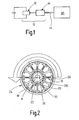
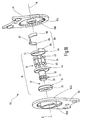
- a drive unit 10 has an engine 12 and a gear stage 14 provided on the output side of the engine 12.
- the motor 12 is an electronically commutated motor with a stator 16, the stator poles 18 are arranged in a star shape about an axis A.
- Axis A perpendicular to the plane of the drawing defines the following directions in cylindrical coordinates.
- the motor 12 is provided as a double-rotor motor, short Duomotor, with an inner rotor 22 and an outer rotor 24.
- Irmenrotor 22 and outer rotor 24 rotate about the axis A and carry along the stator 16 facing peripheral surface permanent magnets 26 which are alternately poled in the circumferential direction.
- All permanent magnets 26 used in the present application preferably have a high permeability, for example, by containing metals from the group of rare earths.
- An inner yoke ring 28 associated with the inner rotor 22 and an outer yoke ring 30 associated with the outer rotor 24 close the magnetic flux. If appropriate, the two return rings 28 and 30 can simultaneously serve as carriers of the permanent magnets 26.
- the outer rotor 24 provides a larger torque due to the magnetic forces acting on a larger radius (compared to the inner rotor 22).
- the motor is preferably formed in a hollow shaft design, ie, the area around the axis A is released.
- the number of permanent magnets 26 is chosen so that their ratio to the number of stator poles 18 is not equal to 2: 3 or 3: 2, whereby the rotation of the inner rotor 22 and outer rotor 24 deviates from the rotation of the magnetic field in the stator 16.
- the inner rotor 22 has ten permanent magnets 26 and the outer rotor 24 fourteen permanent magnets 26. According to the different number of permanent magnets 26 rotate in the engine 12, the inner rotor 22 and the outer rotor 24 in the present case with different speeds (5: 7) and also in opposite directions of rotation, which is indicated in the drawing by arrows.
- an axial construction can also be realized, i. the rotors (pancake) and the stator are arranged axially one behind the other.
- the gear 14 is used to suppress the speed of the motor 12 while translating the output from the engine 12 torque.
- the gear 14 is designed as a differential gear, wherein different types are described below. For each type exists both a design as a gear planetary differential gear with flat, toothed planet gears and a preferred embodiment as a friction planetary differential gear with cylindrical, smooth planetary rollers, which - as the sun - can be hollow or solid.
- the first gear stage type is a one-stage planetary differential gear, which will be described first in the friction wheel design.
- the gear stage 14 is aligned with the central axis A of the motor 12.
- Around the axis A around a sun gear 32 is arranged, on the peripheral surface of three planetary rollers 34 roll along, which in turn are surrounded by a ring gear 36.
- the ring gear 36 provides a radial bias and thus good rolling of the planetary rollers 34 without slippage.
- An annular web 38 carries on axial pin planetary rollers 34th
- the inner rotor 22 is rotatably connected to the sun gear 32, while the outer rotor 24 is rotatably connected to the ring gear 36.
- the web 3 8 serves as the output of the drive unit 10.
- the respective diameters are matched in their dimensions to the speeds, torques and directions of rotation of the rotors 22 and 24.
- the axial lengths of the sun gear 32, planetary rollers 34 and ring gear 36 are selected to be so large that by means of the gear stage 14, a bearing of the inner rotor 22 and the outer rotor 24 takes place relative to the stator 16.
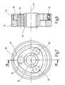
- the second gear stage type is a multi-stage planetary differential gear, which in turn is described in the radially layered friction wheel design, but is also possible in a gear design. Likewise, massive and / or hollow components can be used again.
- Around the axis A around a sun gear 32 is again arranged, on the peripheral surface of a layer of inner planetary rollers 34 is arranged.
- a first outer planetary roller 40 and a second outer planetary roller 42 each having approximately half the axial length of an inner planetary roller 34, wherein the second outer planetary roller 42 has a relation to the first outer planetary roller 40 slightly smaller diameter, which is for example the use of cylindrical rollers on the one hand from the metric and on the other hand from the imperial standard series can be realized in a simple manner.
- a cylindrical shape and a different shape for the rolling elements can be used.
- This bias of the two radially layered rows of rollers ensure that all roles support each other and a concentric radially symmetrical arrangement results, which is without slippage, so that there is a high efficiency of the transmission stage 14.
- a web and thus an inner bearing of the planetary rollers is not required, but not excluded.
- the sun gear 32 may be provided at the end with radially outwardly facing ribs to secure the planetary rollers in the axial direction, which is also possible with the other types of gear stages.
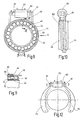
- the two outer rings 44 and 46 are constructed in principle the same, so that in the following only the first outer ring 44 is described.
- the first outer ring 44 has an elastic metal ring 48 made of steel, which rests on its radially inner side of the first outer planetary rollers 40 and is formed with a smaller inner diameter than it requires the geometric arrangement of the enclosed rollers to apply the bias.
- On the radially outer side and on the two axial end faces of the metal ring 48 is located in an elastomer bed 50 of the first outer ring 44.
- the metal ring 48 and the plastic elastomeric bed 50 together ensure a very uniform contact pressure.
- the elastomer bed 50 insulates the running noise and softens torque surges.
- the described two-part construction of the first outer ring 44 can also be realized in the ring gear 36 or 36 'of the first gear stage type.
- a holder 52 is provided, which is designed in two parts for the purpose of assembly and the elastomer bed 50 radially outwardly and with two rims over the front overlaps, which is also possible with the other types of gear ,
- the metal ring 48 and the elastomer bed 50 are preferably formed continuously in the circumferential direction, but they can also be slotted or split, in particular slotted arrow shape, for example, when they are rotatably connected to the holder 52.
- the elastomer bed 50 is preferably good thermal conductivity, for example by incorporation of metallic or other thermally conductive fibers or filling cavities or cutouts with a thermally conductive material. Between the metal ring 48 and the elastomer bed 50 may also be provided a thermal paste.
- the small difference in diameter between the first outer planetary rollers 40 and the second outer planetary rollers 42 and, consequently, the inner diameters of the first outer ring 44 and the second outer ring 46 causes a difference in the rotational speeds of the two outer rings 44 and 46.
- This small rotational speed difference becomes large Reduction (eg 200) of the gear stage 14 exploited when it is connected to the motor 12.
- the first outer ring 44 more precisely its holder 52, for example, fixed to the housing, that is connected to the stator 16.
- the sun gear 32 is used as the drive, while the second outer ring 46 serves as the output 54.
- the second outer ring 46 serves as the output 54.
- designed as a hollow shaft output shaft is mounted with a bell-shaped end piece on the second outer ring 46, more precisely on the holder 52.
- Present the second outer ring 46 rotates in the same direction to the sun gear 32.
- the selected structure of the second gear stage type makes separate storage of the sun gear 32 and thus of the inner rotor 22 and outer rotor 24 and the second outer ring 46, ie the output 54 unnecessary, but does not exclude ,
- the bearing of the inner rotor 22 and outer rotor 24 in the gear stage 14 has the advantage that it is free of play and thus causes a silent running of the inner rotor 22 and outer rotor 24.
- the (smaller) second outer ring 46 is fixed to the housing and the (larger) first outer ring 44 the output, which causes an opposite rotation of the sun gear 32 and the first outer ring 44.
- the outer rings 44 and 46 With an optional fixing of the outer rings 44 and 46 on the housing and a resulting change of the output, for example by means of two latch systems or a circuit described in more detail below, a reversal of direction of the output can be achieved with the same direction of rotation of the sun gear 32.
- the required electronics of the motor 12 can then be constructed much simpler, which simplifies the production of the motor 12.
- the second gear stage type can be further modified by a different number of roller sets.
- one or more axially successively arranged sun gears, an equal number of inner planetary rollers in a corresponding axial arrangement, optionally a set of central planetary rollers for synchronization, one or more sets of axially successively arranged, outer planetary rollers and an equal number of outer rings in corresponding be provided axial arrangement.
- the small speed difference is tapped according to the manner described between two adjacent transmission elements.
- the third gear stage type is again a single-stage planetary differential gear, which in turn is described in a radially layered friction wheel design, but also in a gear design is possible.
- the gear stage 14 is aligned with the central axis A of the motor 12.
- About the axis A around a sun gear 32 is arranged on the peripheral surface of three planetary rollers 34 roll along.
- the ungraded planetary rollers 34 are enclosed by an annular first ring gear 36, which has a low elasticity, that is relatively stiff.
- the planetary rollers 34 are enclosed by a second ring gear 56, which has a higher elasticity and a smaller inner circumference than the first ring gear 36.
- the two ring gears 36 and 56 provide a radial bias with high contact pressure and thus for a good rolling of the planetary rollers 34 without slippage, wherein the sun gear 32 compensates for the radial forces.
- the ratio of the ring gear inner circumferences for a translation of 200 need not be 200/199, but can be chosen generous and thus tolerances insensitive.
- a web which supports the planetary rollers may be provided as a drive or a bearing cage fixing the planetary rollers in a manner analogous to the first gear stage type.
- sun gears of different elasticity can be provided in a modified embodiment, two axially successively arranged sun gears of different elasticity in combination with a ring gear or other combinations of continuous or divided sun gears and ring gears of different elasticity.
- the planetary rollers can also be stepped.
- the second ring gear 56 is received by an elastomer bed 50 enclosing this radially outside, for example a rubber ring, which in turn is arranged radially inside a holder 52 .
- the elastomer bed 50 can also be regarded as a further constituent of the ring gear 56 having a metal ring.
- elastic spokes for the second ring gear 56 or an axial or radial tap possibly with the interposition of a pot with deformable walls or a damper elements having perforated disc may be provided.
- the slightly non-uniform movement of the ring gear 56 is preferably not or only slightly compensated.
- the first ring gear 36 is fixed to the housing, e.g. connected to the stator 16.
- the sun gear 32 serves as the drive
- the second ring gear 56 serves as the output 54.
- the respective diameter must be at most in the same orders of magnitude, so that there is a further translation option by choosing the diameter.
- the axial lengths of the sun gear 32, planetary rollers 34 and ring gear 36 are selected to be so large that by means of the gear stage 14, a bearing of the inner rotor 22 and the outer rotor 24 takes place relative to the stator 16.
- the gear 14 may be designed as a manual transmission, by means of which in a single, always the same direction of rotation of the motor 12, the direction of rotation of the output 54 between two different output directions is switchable, which is explained in more detail below with reference to the second gear stage type.
- a set of inner planetary rollers 34 sitting on the sun gear 32 a set of inner planetary rollers 34, on which in turn a set of first planetary rollers 40 is arranged, which is held biased by a first outer ring 44, and axially offset therefrom a set of second planetary rollers 42, which is held biased by a second outer ring 46.
- the second outer ring 46 forms part of the output 54.
- the axial length of the inner planetary rollers 34 is selected so that axially adjacent to the first outer ring 44 on the side facing away from the second outer ring 46 side, a third outer ring 58 is arranged, which with bias the inner planet rolls 34 directly includes.
- the outer diameter of the first outer ring 44 and the third outer ring 58 are at least approximately coincident.
- a wrap spring 60 is supported fixed to the housing at its center and otherwise wrapped with a portion of their turns around the first outer ring 44 and with another part of their turns around the third outer ring 58.
- a permanent magnet is arranged in each case as a holding magnet 61, wherein the mutually facing poles of the two holding magnets 61 repel each other.
- the holding magnets 61 preferably have a high permeability, for example by containing metals from the group of rare earths.
- a core 62 made of soft iron is arranged, around which a coil 63 which can be energized with an optional polarity is wound.
- a manual transmission with a positive solution is conceivable in a modified version.
- the holding magnets 61 can recordable manner be arranged on toothed pawls 64 which lock the respective teeth carrying a outer rings switchable. The operation is as described above.
- the locking device can also serve to lock torques in the idle state, which are initiated by the output 54. Such a lock need not take place at the gear stage 14, it may also be provided between the engine 12 and gear 14.
- the output shaft of the motor 12 is provided on the one hand with a motor pinion 66 which engages in an intermediate gear 67 connected to the sun gear 32, and on the other hand frictionally connected to a control disk 68 with two cams 68 '.
- two spring-loaded ratchets 64 engage at least approximately positively in the intermediate gear 67 and lock this, in particular against the output side introduced torques.
- the control disk 68 is rotated, wherein the cams 68 'come into abutment against control contours 64' of the pawls 64 and thereby dig the pawls 64 from the intermediate gear 67, as in Fig. 13B shown.
- the idler gear 67 can now be driven without hindrance, wherein the frictional engagement with the control disk 68 is preferably canceled.
- the control disk 68 is not frictionally engaged with a rotating axis, but rotatably with the non-rotating motor part and this in turn rotatably supported by a small angular range to the housing.
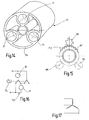
- the inventively provided drive unit 10 is not limited to a combination of a single motor 12 with a single gear stage 14. Thus, it may be useful for certain performance requirements to combine multiple engines 12, for example, to meet time-varying requirements.
- a motor carrier 70 a plurality of motor wells 71 are provided, which are each arranged around a central bearing for a common idler gear 67.
- the multi-motor 72 thus formed is then coupled by means of the intermediate gear 67 to a gear stage 14, for example to a sun gear 32 of one of the gear stage types described above.
- the mechanically parallel interconnected motors 12 are electrically operated normally in series. In Fig. 16 this is illustrated by two motors 12 and extendable in a conventional manner to a plurality of motors. Between the motors 12, one or more relays 74 are provided, including electronic replacement circuits are to be understood. Normally, due to the series connection, the operating voltage is distributed at least approximately uniformly over the existing motors 12.
- the drive unit 10 may be desirable for the drive unit 10 to output a higher speed and / or a higher torque. Such a situation is - in the case of use of the drive device 10 in a vehicle - a crash.
- the driven by the drive unit 10 devices should then occupy certain positions as quickly as possible in order to increase occupant protection, for which it is accepted that the drive unit 10 may subsequently be unusable.
- Another particular situation would be a quick adjustment of one or more adjusters of a vehicle seat over a large area, for example, a folding forward of the backrest (free-pivoting) in combination with a longitudinal adjustment to facilitate access to a rear row of seats (easy-entry).
- a mechanical solution for the quick adjustment would be in the second and third gear stage type in the training as a gearbox with selectable gear ratio feasible if the difference in the geometries of the outer rings 44 and 46 or the elasticities of the ring gears 36 and 5 6 is sufficiently large.
- the existing in the manual transmission locking device which alternately determines exactly by switching an outer ring 44 or 46 or exactly one ring gear 36 or 56, different speeds and thus different gear ratios can be generated at the output. If the direction of rotation of the motor 12 remains the same, the direction of rotation of the output changes, which corresponds to the situation described above for the unidirectional motor. In order to produce a constant direction of rotation of the output is - except the switching of the locking device - still change the direction of rotation of the motor 12.
- the existing relay 74 are operated in the particular situation by a vehicle electronics, not shown, so that the series circuit is canceled and the motors 12 are connected in parallel.
- the power consumption of the individual motors 12 and the multi-motor 72 as a whole increases, at least in the short term, preferably until the driven devices have reached the desired positions. Thermodynamic effects can be neglected due to the short operating times.
- the control of the relay 74 can - in the case of application for a crash situation - take place before the actual crash, if the existing crash sensors of the vehicle electronics provide indications of an imminent crash. The solution is thus presave-capable.
- the current supply with the star connection is also particularly well suited for a combination of the duo motor with a locking device.
- One of the two rotors of the duo engine is mechanically blocked when the special situation by means of the locking device.
- the downstream transmission stage 14 then acts as a differential gear with higher ratio (less lesser reduction).
- the other rotor runs after switching to the center tap because of the lower resistance with higher power consumption, which then ultimately causes the desired increase in power output 54.
- the inventively provided drive unit 10 is used in the present case for driving a adjuster 80 within a vehicle.
- the adjuster 80 has in the general case two relatively movable components, between which the drive unit 10 acts with its output 54.
- the low speed of the output 54 provides a large torque.
- Means for implementing the rotational movement of the output 54 into a linear movement in the adjuster 80 may be provided. It can also be provided for each adjustment direction of the adjuster 80 own drive unit.
- adjuster 80 would be in the range of vehicle seats a Lehnenne Trentseinsteller, especially in the form of a self-locking gear fitting, acting between two gear members of a four-joint seat height adjuster, a front edge of a seat cushion pivoting seat tilt adjuster, or a vehicle seat rail-longitudinally moving seat length adjuster.
- two similar, individual adjuster 80 cooperate to move a component together.
- individual adjuster 80 present, which are coupled in a known solution in pairs by means of a rotatable transmission rod and synchronized.
- a separate drive unit 10 can be provided for each individual adjuster 80 of a pair, which are then synchronized, for example, by the electronics for electronic commutation of the motor 12 or via the rigidity of the structure of the vehicle seat ,
- an adjuster 80 with a load-receiving transmission is described as a preferred application of the drive unit 10 according to the invention, which is designed as a self-locking gear fitting and for example, the inclination adjustment of a backrest of the vehicle seat is used.
- This adjuster 80 has a first fitting part 81 with a ring gear formed like a ring gear 81 a and with the first fitting part 81 in gear connection, second fitting part 82 with a pronounced gear 82a, wherein the two fitting parts 81 and 82 form the load-absorbing transmission.
- the diameter of the tip circle of the gear 82a is smaller than the diameter of the root circle of the ring gear 81a by about one tooth height, and the number of teeth of the gear wheel 82a is smaller than the number of teeth of the ring gear 81a.
- a relative rolling movement of the toothed wheel 82a on the ring gear 81a is possible, which manifests itself as relative rotation of the two fitting parts 81 and 82 with a superimposed wobbling motion.
- a first collar 8 1 b is formed on the first fitting part 81 concentric with the ring gear 81 a, which defines a minor axis B concentric with the gear 82 a, a second collar 82 b formed concentric to the gear 82 a (or instead a sleeve pressed), which the central axis A defined.
- the diameter of the second collar 82b is greater than that of the first collar 81b.
- the drive unit 10 which in the present case consists of a slightly modified motor 12 whose second rotor and first gear stage are not shown here and which is combined with a gear stage 14 of the second gear stage type described above in friction wheel design, but could also be constructed in a different combination , Space-optimized arranged in the center of the load-bearing transmission is integrated into the second fitting part 82, more precisely in the second collar 82b.
- the stator 16 is rotatably connected to the second collar 82b in the axially remote from the first fitting part 81 half, wherein the electronics not shown is disposed within the second collar 82b on the side facing away from the first fitting 81 side.
- the illustrated inner rotor 22 as well as the outer rotor are disposed within the collar 82b, with the hollow sun gear 32 supported by the gear stage 14, in this case continuously clearance-free to the second fitting 82.
- the inner planetary rollers 34 are radially stacked on the sun gear 32 while the first outer planetary rollers 40 and the second outer planetary rollers 42 are laminated on the inner planetary rollers 34.
- the first outer ring 44 and the second outer ring 46 clamp the planetary rollers together and at the same time ensure a play-free mounting of the inner rotor 22.
- the first outer ring 44 is pressed into the second collar 82b, ie as the stator 1 6 fixed to the housing, or the second collar 82b forms itself the first outer ring 44th
- the second outer ring 46 which also serves as the output 54 of the drive unit 10, is rotatable with its smaller diameter within the second collar 82b, wherein the second collar 82b is formed as a plain bearing bush or such on the axially the first fitting part 81 facing the end of the second Collar collar 82b is pressed.
- an axially projecting cam segment 85 is formed, which extends over about a quarter of the circumference.
- the driver segment 85 can also be provided on a separately formed and with the second outer ring 46 rotatably connected ring.
- In the same plane as the driver segment 85 are two arranged on the first collar train 81 a, curved wedge segments 86, said driver segment 85 with play between the narrow sides of the wedge segments 86 sums.
- a between the facing broad sides of the wedge segments 86 summarizing spring 87 pushes the wedge segments 86 apart in the circumferential direction.
- the cam segment 85 and the wedge segments 86 together define an eccentric 88.
- the drive unit 10 is formed as a hollow shaft drive, i. Both the engine 12 and the transmission stage 14, the central area around the axis A remains free, so that if necessary, but a transmission rod or the like can be installed.
- the large mass of the adjuster 80 offers advantages in the acoustic range. Due to the fixed, tight and in the preloaded friction wheel design and backlash-free connection of the small rotating mass of the inner rotor 22 to the large mass of the adjuster 80, the structure-borne sound vibrations of the inner rotor 22 are well forwarded, but due to the large mass to be accelerated only too small amplitudes.
- the large mass of the adjuster 80 provides through the contact between stator 16 and load-receiving gear also thermodynamic advantages.
Landscapes
- Engineering & Computer Science (AREA)
- Power Engineering (AREA)
- Aviation & Aerospace Engineering (AREA)
- Transportation (AREA)
- Mechanical Engineering (AREA)
- Connection Of Motors, Electrical Generators, Mechanical Devices, And The Like (AREA)
- Retarders (AREA)
- Seats For Vehicles (AREA)
Priority Applications (1)
| Application Number | Priority Date | Filing Date | Title |
|---|---|---|---|
| PL05738723T PL1735178T3 (pl) | 2004-04-15 | 2005-04-05 | Moduł napędowy nastawnika siedzenia do pojazdu |
Applications Claiming Priority (2)
| Application Number | Priority Date | Filing Date | Title |
|---|---|---|---|
| DE102004019463A DE102004019463A1 (de) | 2004-04-15 | 2004-04-15 | Antriebseinheit für einen Fahrzeugsitz |
| PCT/DE2005/000631 WO2005100080A1 (de) | 2004-04-15 | 2005-04-05 | Antriebseinheit eines einstellers eines fahrzeugsitzes |
Publications (2)
| Publication Number | Publication Date |
|---|---|
| EP1735178A1 EP1735178A1 (de) | 2006-12-27 |
| EP1735178B1 true EP1735178B1 (de) | 2009-02-11 |
Family
ID=34966219
Family Applications (1)
| Application Number | Title | Priority Date | Filing Date |
|---|---|---|---|
| EP05738723A Expired - Lifetime EP1735178B1 (de) | 2004-04-15 | 2005-04-05 | Antriebseinheit eines einstellers eines fahrzeugsitzes |
Country Status (7)
| Country | Link |
|---|---|
| US (1) | US7345390B2 (pl) |
| EP (1) | EP1735178B1 (pl) |
| JP (1) | JP4739323B2 (pl) |
| CN (1) | CN100575144C (pl) |
| DE (2) | DE102004019463A1 (pl) |
| PL (1) | PL1735178T3 (pl) |
| WO (1) | WO2005100080A1 (pl) |
Families Citing this family (19)
| Publication number | Priority date | Publication date | Assignee | Title |
|---|---|---|---|---|
| DE102004019466B4 (de) * | 2004-04-15 | 2006-07-13 | Keiper Gmbh & Co.Kg | Einstellvorrichtung für einen Fahrzeugsitz |
| DE102004019469A1 (de) * | 2004-04-15 | 2005-11-10 | Keiper Gmbh & Co.Kg | Antriebseinheit in einem Fahrzeug |
| DE102006005906A1 (de) | 2005-08-23 | 2007-08-30 | Keiper Gmbh & Co.Kg | Getriebestufe |
| JP4260799B2 (ja) | 2005-12-02 | 2009-04-30 | 本田技研工業株式会社 | 電動機および電動機の駆動方法 |
| DE102006045483B4 (de) * | 2006-09-27 | 2016-01-21 | Faurecia Autositze Gmbh | Verstellsystem für einen Fahrzeugsitz |
| US7600801B2 (en) * | 2006-12-20 | 2009-10-13 | Globe Motors, Inc. | Seat storage actuator |
| DE102006062613A1 (de) * | 2006-12-29 | 2008-07-03 | Thoms, Michael, Dr. | Permanentmagnetmaschine |
| US7965007B2 (en) * | 2009-05-05 | 2011-06-21 | Herbert Carey Dahlen | Three dimensional motor generator system |
| JP5471158B2 (ja) * | 2009-08-21 | 2014-04-16 | アイシン精機株式会社 | モータ制御装置及び車両用シート制御装置 |
| CA2775497C (en) | 2009-08-31 | 2014-05-06 | New Core, Inc. | Multiple induction electric motor and vehicle |
| ES2703608T3 (es) * | 2011-07-14 | 2019-03-11 | Jean I Tchervenkov | Conjunto de rueda que define un motor/generador |
| US8810099B2 (en) * | 2012-03-05 | 2014-08-19 | Cheng-Chi Huang | Power magnetic planetary gear set |
| AT514263B1 (de) * | 2013-04-17 | 2016-06-15 | Manfred Dr Schrödl | Elektrische Maschine |
| US9806587B2 (en) | 2013-08-26 | 2017-10-31 | Robert Ross | System and method for stator construction of an electric motor |
| JP6044848B2 (ja) * | 2014-03-18 | 2016-12-14 | 株式会社デンソー | 回転電機 |
| TWI538363B (zh) | 2014-12-02 | 2016-06-11 | 財團法人工業技術研究院 | 順應性馬達結構及其製造方法 |
| US9821681B2 (en) * | 2016-01-25 | 2017-11-21 | Ford Global Technologies, Llc | Vehicle seat position sensing |
| JP2019009899A (ja) * | 2017-06-23 | 2019-01-17 | 株式会社デンソー | 駆動装置 |
| DE102020115263B4 (de) | 2020-06-09 | 2022-04-14 | Gkn Sinter Metals Engineering Gmbh | Elektrischer Motor und Verfahren zum Betrieb eines elektrischen Motors |
Family Cites Families (57)
| Publication number | Priority date | Publication date | Assignee | Title |
|---|---|---|---|---|
| US1463638A (en) | 1922-07-14 | 1923-07-31 | Siemens Schuckertwerke Gmbh | Reversing gear |
| GB601519A (en) | 1944-04-01 | 1948-05-07 | Kibbey Whitman Couse | Improvements in variable speed electric drives |
| US2864017A (en) * | 1955-11-28 | 1958-12-09 | Waltscheff Dimo Dimitroff | Inducto-motive power apparatus with a plurality of rotors |
| GB879040A (en) | 1959-01-14 | 1961-10-04 | John M Perkins & Smith Ltd | Epicyclic gearing |
| US4367424A (en) * | 1981-04-29 | 1983-01-04 | The Bendix Corporation | Eccentricity modifier for epicyclic gear actuators |
| US4375047A (en) * | 1981-07-23 | 1983-02-22 | General Signal Corporation | Torque compensated electrical motor |
| DE3129672C1 (de) | 1981-07-28 | 1982-10-28 | Privates Institut für physikalisch technische Auftragsforschung GmbH, 6107 Reinheim | Getriebe mit außenverzahnten und innenverzahnten Zahnrädern, das gegenüber einem auf der Abtriebsseite wirkenden Drehmoment selbsthemmend ist |
| DE3233472A1 (de) | 1982-09-09 | 1984-03-15 | Alfred Teves Gmbh, 6000 Frankfurt | Elektromechanischer sitzversteller, insbesondere fuer kraftfahrzeugsitze |
| DE3301139A1 (de) * | 1983-01-14 | 1984-07-26 | Brose Fahrzeugteile GmbH & Co KG, 8630 Coburg | Sitzverstellung, insbesondere fuer einen kraftfahrzeugsitz |
| FR2567462B1 (fr) | 1984-07-10 | 1987-08-14 | Cousin Cie Ets A & M Freres | Articulation a vis reversible, plus specialement pour reglage de sieges de vehicules terrestres, nautiques et aeriens |
| JP2607889B2 (ja) * | 1987-08-04 | 1997-05-07 | 光洋精工株式会社 | 減速電動機 |
| US4749305A (en) * | 1987-08-31 | 1988-06-07 | Ingersoll-Rand Company | Eccentric-weight subassembly, and in combination with an earth compactor drum |
| DE3804352A1 (de) | 1988-02-12 | 1989-08-24 | Keiper Recaro Gmbh Co | Verstellvorrichtung fuer sitze |
| JPH0246969A (ja) | 1988-08-09 | 1990-02-16 | Furukawa Alum Co Ltd | 熱交換器用ろう付アルミ偏平チューブの製造方法 |
| CN1035211A (zh) * | 1988-09-13 | 1989-08-30 | 曾剑良 | 双转子电机 |
| US5199764A (en) | 1989-07-24 | 1993-04-06 | Fisher Dynamics Corporation | Power linear seat recliner |
| JP2542093B2 (ja) | 1989-11-21 | 1996-10-09 | 三菱電機株式会社 | 遊星歯車式減速スタ―タ装置 |
| US5334898A (en) * | 1991-09-30 | 1994-08-02 | Dymytro Skybyk | Polyphase brushless DC and AC synchronous machines |
| DE4325391C2 (de) | 1993-07-29 | 1997-08-21 | Keiper Recaro Gmbh Co | Verteilergetriebe für Stellvorrichtungen von Fahrzeugsitzen |
| DE9315382U1 (de) | 1993-10-12 | 1995-02-09 | Robert Bosch Gmbh, 70469 Stuttgart | Stellantrieb mit einem elektrischen Antriebsmotor und einem diesem nachgeordneten Getriebe |
| DE4340696C1 (de) | 1993-11-30 | 1995-06-29 | Keiper Recaro Gmbh Co | Rückenlehnenverstellvorrichtung für Sitze, insbesondere Kraftfahrzeugsitze |
| DE4341112C1 (de) | 1993-12-02 | 1995-06-29 | Erhard Buettner | Umlaufrädergetriebe mit stufenloser Drehzahlverstellung |
| DE4425193C1 (de) | 1994-07-16 | 1995-11-09 | Bosch Gmbh Robert | Drehzahlverstellbarer EC-Gleichstrommotor |
| DE19527982C2 (de) | 1995-07-31 | 2002-08-22 | Fhp Motors Gmbh | Elektronisch kommutierter Elektromotor |
| JPH0974713A (ja) | 1995-09-04 | 1997-03-18 | Toyota Motor Corp | 電動モータ |
| JPH09275673A (ja) * | 1996-03-28 | 1997-10-21 | Tai-Haa Yan | 共通構造を有する三層電気機械構造を備えた組合せ 電力駆動装置 |
| DE19642665C2 (de) | 1996-10-16 | 2000-03-16 | Temic Auto Electr Motors Gmbh | Elektromotorische Verstellvorrichtung für einen Kraftfahrzeugsitz |
| DE19709852C2 (de) | 1997-03-11 | 2003-08-21 | Keiper Gmbh & Co Kg | Getriebebaueinheit zur Verstellung von Sitzen, insbesondere Kraftfahrzeugsitzen |
| DE19734536C2 (de) * | 1997-07-30 | 1999-10-28 | Brose Fahrzeugteile | Taumelgetriebe für eine Fahrzeugsitz-Verstelleinrichtung |
| DE19737269C2 (de) | 1997-08-27 | 2000-11-09 | Faure Bertrand Sitztech Gmbh | Kraftfahrzeugsitz mit elektrisch angetriebenem Drehverstellbeschlag |
| DE19737702C2 (de) | 1997-08-29 | 2001-10-18 | System Antriebstechnik Dresden | Rotorlagegeber für einen elektronisch kommutierten Innenläufermotor mit permanetmagnetbestücktem Rotor |
| DE19746595C2 (de) | 1997-10-22 | 2001-07-12 | Bosch Gmbh Robert | Antriebseinheit mit Elektromotor |
| AT408045B (de) * | 1998-01-30 | 2001-08-27 | Schroedl Manfred Dipl Ing Dr | Elektrische maschine |
| EP0945963B1 (en) * | 1998-03-25 | 2003-11-05 | Nissan Motor Co., Ltd. | Motor/generator |
| DE19846501A1 (de) | 1998-10-09 | 2000-04-13 | Bosch Gmbh Robert | Elektrischer Motor |
| DE19858233A1 (de) | 1998-12-17 | 2000-06-29 | Bosch Gmbh Robert | Elektrischer Getriebemotor für Fahrzeugaggregate |
| US6099430A (en) | 1999-08-06 | 2000-08-08 | New Venture Gear, Inc. | Clutching actuator for clutch control system in a drive line apparatus |
| JP4013448B2 (ja) | 2000-05-01 | 2007-11-28 | 株式会社デンソー | 2ロータ型同期機 |
| JP3496595B2 (ja) * | 1999-10-27 | 2004-02-16 | 日産自動車株式会社 | 回転電機 |
| DE19959956A1 (de) | 1999-12-13 | 2001-06-21 | Breed Automotive Tech | Gurtaufroller |
| DE19962225A1 (de) | 1999-12-22 | 2001-06-28 | Breed Automotive Tech | Vorrichtung zur Verstellung der Neigung einer Rückenlehne eines Fahrzeugsitzes |
| DE29922592U1 (de) | 1999-12-22 | 2000-04-20 | Breed Automotive Technology, Inc., Lakeland, Fla. | Vorrichtung zum Verstellen einer Kopfstütze an einer Rückenlehne eines Fahrzeugsitzes |
| DE10002485A1 (de) | 2000-01-21 | 2001-08-02 | Mannesmann Sachs Ag | Wickelkörper zur Aufnahme einer Wicklung für einen elektro-magneto-mechanischen Wandler sowie elektro-magneto-mechanischer Wandler |
| DE10034289B4 (de) | 2000-07-14 | 2006-10-26 | Bayerische Motoren Werke Ag | Sitz |
| JP4269544B2 (ja) * | 2000-09-14 | 2009-05-27 | 株式会社デンソー | 複数ロータ型同期機 |
| US6547332B2 (en) | 2001-01-24 | 2003-04-15 | Fishers Dynamics Corporation | Constant engagement linear mechanism |
| DE10120854C1 (de) | 2001-04-27 | 2002-08-08 | Keiper Gmbh & Co | Getriebebeschlag für eine Fahrzeugsitzeinstellvorrichtung |
| JP3578451B2 (ja) | 2001-07-23 | 2004-10-20 | 日産自動車株式会社 | 駆動装置 |
| FR2829813A1 (fr) | 2001-09-14 | 2003-03-21 | Valeo Equip Electr Moteur | Reducteur a train epicycloidal notamment pour demarreur de vehicule automobile et demarreur equipe d'un tel reducteur |
| GB2383101A (en) | 2001-12-15 | 2003-06-18 | Roger David Harrison | Regenerative braking device with uni-directional clutches |
| DE10163321C1 (de) | 2001-12-21 | 2003-08-14 | Minebea Co Ltd | Spalttopfmotor |
| JP3967971B2 (ja) | 2002-07-02 | 2007-08-29 | 株式会社今仙電機製作所 | 自動車シートのリクライニング装置 |
| JP4082126B2 (ja) * | 2002-08-08 | 2008-04-30 | 日産自動車株式会社 | 複軸多層モータのアウターロータ支持ベアリング取り付け構造 |
| JP3799022B2 (ja) * | 2003-02-24 | 2006-07-19 | 酒井重工業株式会社 | 振動機構及び振動ローラ |
| US20050035678A1 (en) * | 2003-08-11 | 2005-02-17 | Ward Terence G. | Axial flux motor mass reduction with improved cooling |
| TWI272757B (en) * | 2003-11-20 | 2007-02-01 | Sumitomo Heavy Industries | Motor built-in cylinder |
| US7152922B2 (en) | 2004-05-07 | 2006-12-26 | Fisher Dynamics Corporation | Powered remote release actuator for a seat assembly |
-
2004
- 2004-04-15 DE DE102004019463A patent/DE102004019463A1/de not_active Ceased
-
2005
- 2005-04-05 CN CN200580012030A patent/CN100575144C/zh not_active Expired - Fee Related
- 2005-04-05 DE DE502005006602T patent/DE502005006602D1/de not_active Expired - Lifetime
- 2005-04-05 JP JP2007507656A patent/JP4739323B2/ja not_active Expired - Fee Related
- 2005-04-05 PL PL05738723T patent/PL1735178T3/pl unknown
- 2005-04-05 EP EP05738723A patent/EP1735178B1/de not_active Expired - Lifetime
- 2005-04-05 WO PCT/DE2005/000631 patent/WO2005100080A1/de not_active Ceased
-
2006
- 2006-10-13 US US11/580,821 patent/US7345390B2/en not_active Expired - Fee Related
Also Published As
| Publication number | Publication date |
|---|---|
| DE502005006602D1 (de) | 2009-03-26 |
| PL1735178T3 (pl) | 2009-06-30 |
| EP1735178A1 (de) | 2006-12-27 |
| JP2007533286A (ja) | 2007-11-15 |
| US20070029888A1 (en) | 2007-02-08 |
| US7345390B2 (en) | 2008-03-18 |
| CN1942338A (zh) | 2007-04-04 |
| DE102004019463A1 (de) | 2005-11-10 |
| WO2005100080A1 (de) | 2005-10-27 |
| CN100575144C (zh) | 2009-12-30 |
| JP4739323B2 (ja) | 2011-08-03 |
Similar Documents
| Publication | Publication Date | Title |
|---|---|---|
| EP1735896B1 (de) | Einsteller für einen fahrzeugsitz | |
| EP1735178B1 (de) | Antriebseinheit eines einstellers eines fahrzeugsitzes | |
| DE102004019471B4 (de) | Antriebseinheit für einen Fahrzeugsitz | |
| EP3962805B1 (de) | Getriebeanordnung, antriebseinheit und verfahren zum betreiben einer antriebseinheit für ein fahrzeug | |
| DE19841159C2 (de) | Antriebsanordnung für ein Kraftfahrzeug | |
| DE69807777T2 (de) | Reibrollen-Getriebe | |
| DE102004019465B4 (de) | Antriebseinheit für einen Fahrzeugsitz | |
| DE102004019469A1 (de) | Antriebseinheit in einem Fahrzeug | |
| WO2014118284A2 (de) | Vorrichtung zur elektromechanischen erzeugung von rotation - elektrischer umlaufräderantrieb | |
| WO2005046030A1 (de) | Getriebe-antriebseinheit | |
| EP2501961B1 (de) | Spannungswellengetriebe | |
| DE102013225290B4 (de) | Magnetmotor mit variablem Feld und Elektrofahrzeug | |
| EP2129568A1 (de) | Getriebe für fahrzeuglenkvorrichtung | |
| WO2012152727A2 (de) | Planetengetriebeanordnung für einen sitzverstellmechanismus und verfahren zum betrieb einer solchen planetengetriebeanordnung | |
| DE102004019468B4 (de) | Antriebseinheit für einen Fahrzeugsitz | |
| EP2838756A1 (de) | Bremsvorrichtung für eine direkt elektromechanisch aktuierte planetengetriebeanordnung eines sitzverstellmechanismus und verfahren zum betrieb einer bremsvorrichtung | |
| EP3529512B1 (de) | Kupplungsanordnung für ein hybridfahrzeug mit einer reibungskupplung und einer fliehkraftkupplung | |
| DE202004020880U1 (de) | Einsteller für einen Fahrzeugsitz | |
| EP1224403A1 (de) | Doppelkupplung mit einem elektromagneten | |
| EP1689631B1 (de) | Überlagerungslenkung | |
| DE29924088U1 (de) | Antrieb für Verstellvorrichtungen in Kraftfahrzeugen | |
| EP1781940B1 (de) | Startervorrichtung zum andrehen von brennkraftmaschinen | |
| DE10042398A1 (de) | Motor mit integriertem Harmonicdrive-Getriebe | |
| DE10021368A1 (de) | Mechatronischer Aktuator | |
| DE102021125002A1 (de) | Kupplungsanordnung und elektrischer Achsantriebsstrang |
Legal Events
| Date | Code | Title | Description |
|---|---|---|---|
| PUAI | Public reference made under article 153(3) epc to a published international application that has entered the european phase |
Free format text: ORIGINAL CODE: 0009012 |
|
| 17P | Request for examination filed |
Effective date: 20060506 |
|
| AK | Designated contracting states |
Kind code of ref document: A1 Designated state(s): DE FR GB IT PL |
|
| DAX | Request for extension of the european patent (deleted) | ||
| RBV | Designated contracting states (corrected) |
Designated state(s): DE FR GB IT PL |
|
| 17Q | First examination report despatched |
Effective date: 20080415 |
|
| GRAP | Despatch of communication of intention to grant a patent |
Free format text: ORIGINAL CODE: EPIDOSNIGR1 |
|
| GRAS | Grant fee paid |
Free format text: ORIGINAL CODE: EPIDOSNIGR3 |
|
| GRAA | (expected) grant |
Free format text: ORIGINAL CODE: 0009210 |
|
| AK | Designated contracting states |
Kind code of ref document: B1 Designated state(s): DE FR GB IT PL |
|
| REG | Reference to a national code |
Ref country code: GB Ref legal event code: FG4D Free format text: NOT ENGLISH |
|
| REF | Corresponds to: |
Ref document number: 502005006602 Country of ref document: DE Date of ref document: 20090326 Kind code of ref document: P |
|
| REG | Reference to a national code |
Ref country code: PL Ref legal event code: T3 |
|
| PLBE | No opposition filed within time limit |
Free format text: ORIGINAL CODE: 0009261 |
|
| STAA | Information on the status of an ep patent application or granted ep patent |
Free format text: STATUS: NO OPPOSITION FILED WITHIN TIME LIMIT |
|
| 26N | No opposition filed |
Effective date: 20091112 |
|
| PG25 | Lapsed in a contracting state [announced via postgrant information from national office to epo] |
Ref country code: IT Free format text: LAPSE BECAUSE OF FAILURE TO SUBMIT A TRANSLATION OF THE DESCRIPTION OR TO PAY THE FEE WITHIN THE PRESCRIBED TIME-LIMIT Effective date: 20090211 |
|
| REG | Reference to a national code |
Ref legal event code: R082 Ref document number: 502005006602 Effective date: 20140710 Ref country code: DE Country of ref document: DE Representative=s name: HOSENTHIEN-HELD UND DR. HELD, DE Ref country code: DE Ref legal event code: R081 Ref document number: 502005006602 Country of ref document: DE Owner name: JOHNSON CONTROLS COMPONENTS GMBH & CO. KG, DE Free format text: FORMER OWNER: KEIPER GMBH & CO. KG, 67657 KAISERSLAUTERN, DE Effective date: 20140710 Ref country code: DE Ref legal event code: R081 Ref document number: 502005006602 Country of ref document: DE Owner name: ADIENT LUXEMBOURG HOLDING S.A.R.L., LU Free format text: FORMER OWNER: KEIPER GMBH & CO. KG, 67657 KAISERSLAUTERN, DE Effective date: 20140710 Ref country code: DE Ref legal event code: R082 Ref document number: 502005006602 Country of ref document: DE Representative=s name: LIEDHEGENER, RALF, DIPL.-ING., DE Effective date: 20140710 Ref country code: DE Ref legal event code: R081 Ref document number: 502005006602 Country of ref document: DE Owner name: ADIENT LUXEMBOURG HOLDING S.A R.L., LU Free format text: FORMER OWNER: KEIPER GMBH & CO. KG, 67657 KAISERSLAUTERN, DE Effective date: 20140710 |
|
| REG | Reference to a national code |
Ref country code: FR Ref legal event code: PLFP Year of fee payment: 12 |
|
| PGFP | Annual fee paid to national office [announced via postgrant information from national office to epo] |
Ref country code: GB Payment date: 20160421 Year of fee payment: 12 |
|
| PGFP | Annual fee paid to national office [announced via postgrant information from national office to epo] |
Ref country code: FR Payment date: 20160421 Year of fee payment: 12 |
|
| REG | Reference to a national code |
Ref country code: DE Ref legal event code: R082 Ref document number: 502005006602 Country of ref document: DE Representative=s name: HOSENTHIEN-HELD UND DR. HELD, DE Ref country code: DE Ref legal event code: R081 Ref document number: 502005006602 Country of ref document: DE Owner name: ADIENT LUXEMBOURG HOLDING S.A.R.L., LU Free format text: FORMER OWNER: JOHNSON CONTROLS COMPONENTS GMBH & CO. KG, 67657 KAISERSLAUTERN, DE Ref country code: DE Ref legal event code: R082 Ref document number: 502005006602 Country of ref document: DE Representative=s name: LIEDHEGENER, RALF, DIPL.-ING., DE Ref country code: DE Ref legal event code: R081 Ref document number: 502005006602 Country of ref document: DE Owner name: ADIENT LUXEMBOURG HOLDING S.A R.L., LU Free format text: FORMER OWNER: JOHNSON CONTROLS COMPONENTS GMBH & CO. KG, 67657 KAISERSLAUTERN, DE |
|
| PGFP | Annual fee paid to national office [announced via postgrant information from national office to epo] |
Ref country code: PL Payment date: 20170330 Year of fee payment: 13 |
|
| PGFP | Annual fee paid to national office [announced via postgrant information from national office to epo] |
Ref country code: DE Payment date: 20170430 Year of fee payment: 13 |
|
| REG | Reference to a national code |
Representative=s name: LIEDHEGENER, RALF, DIPL.-ING., DE Ref country code: DE Ref legal event code: R082 Ref document number: 502005006602 Country of ref document: DE |
|
| GBPC | Gb: european patent ceased through non-payment of renewal fee |
Effective date: 20170405 |
|
| REG | Reference to a national code |
Ref country code: FR Ref legal event code: ST Effective date: 20171229 |
|
| PG25 | Lapsed in a contracting state [announced via postgrant information from national office to epo] |
Ref country code: FR Free format text: LAPSE BECAUSE OF NON-PAYMENT OF DUE FEES Effective date: 20170502 |
|
| PG25 | Lapsed in a contracting state [announced via postgrant information from national office to epo] |
Ref country code: GB Free format text: LAPSE BECAUSE OF NON-PAYMENT OF DUE FEES Effective date: 20170405 |
|
| REG | Reference to a national code |
Ref country code: DE Ref legal event code: R082 Ref document number: 502005006602 Country of ref document: DE Representative=s name: LIEDHEGENER, RALF, DIPL.-ING., DE Ref country code: DE Ref legal event code: R081 Ref document number: 502005006602 Country of ref document: DE Owner name: ADIENT LUXEMBOURG HOLDING S.A R.L., LU Free format text: FORMER OWNER: ADIENT LUXEMBOURG HOLDING S.A.R.L., LUXEMBOURG, LU |
|
| REG | Reference to a national code |
Ref country code: DE Ref legal event code: R119 Ref document number: 502005006602 Country of ref document: DE |
|
| PG25 | Lapsed in a contracting state [announced via postgrant information from national office to epo] |
Ref country code: DE Free format text: LAPSE BECAUSE OF NON-PAYMENT OF DUE FEES Effective date: 20181101 |
|
| PG25 | Lapsed in a contracting state [announced via postgrant information from national office to epo] |
Ref country code: PL Free format text: LAPSE BECAUSE OF NON-PAYMENT OF DUE FEES Effective date: 20180405 |