EP1730767B1 - Dispositif de separation et de positionnement de ponts modules - Google Patents
Dispositif de separation et de positionnement de ponts modules Download PDFInfo
- Publication number
- EP1730767B1 EP1730767B1 EP05733613A EP05733613A EP1730767B1 EP 1730767 B1 EP1730767 B1 EP 1730767B1 EP 05733613 A EP05733613 A EP 05733613A EP 05733613 A EP05733613 A EP 05733613A EP 1730767 B1 EP1730767 B1 EP 1730767B1
- Authority
- EP
- European Patent Office
- Prior art keywords
- module
- bridges
- support element
- placement wheel
- peripheral edge
- Prior art date
- Legal status (The legal status is an assumption and is not a legal conclusion. Google has not performed a legal analysis and makes no representation as to the accuracy of the status listed.)
- Not-in-force
Links
Images


Classifications
-
- H—ELECTRICITY
- H01—ELECTRIC ELEMENTS
- H01L—SEMICONDUCTOR DEVICES NOT COVERED BY CLASS H10
- H01L21/00—Processes or apparatus adapted for the manufacture or treatment of semiconductor or solid state devices or of parts thereof
- H01L21/67—Apparatus specially adapted for handling semiconductor or electric solid state devices during manufacture or treatment thereof; Apparatus specially adapted for handling wafers during manufacture or treatment of semiconductor or electric solid state devices or components ; Apparatus not specifically provided for elsewhere
- H01L21/67005—Apparatus not specifically provided for elsewhere
- H01L21/67011—Apparatus for manufacture or treatment
- H01L21/67132—Apparatus for placing on an insulating substrate, e.g. tape
Definitions
- the invention relates to a device for separating module bridges arranged in a module bridge band or module bridge assembly and for positioning the isolated module bridges on a support element according to the preamble of claim 1.
- WO 03/012734 A1 discloses a method for connecting microchip modules with antennas arranged on a first carrier band for producing a transponder.
- Module bridges which are arranged as an interposer in the form of an interposer band or module bridge band arranged in rows, have hitherto been cut by means of a separating device such that the module bridges detached from the module bridge band isolated. Subsequently, the module bridges are positioned by means of a further device on a stationary support element and stored by a downward sliding movement of this device individually on the stopped support element. Alternatively, the positioning device may be held without downward movement above the support element while the support element moves by means of an upward sliding movement towards the retained module bridge.
- the support element After placing a module bridge on the support element, the support element is moved by a predetermined distance section in its direction in order to record at a new location another module bridge can.
- Such devices require the stopping of the support element during the storage of a module bridge on this. As a result, the throughput of a placement device, which includes such devices, reduced.
- the separate placement of the separation device and the positioning device requires reorienting the module bridge upon receipt of a detached module bridge by the positioning device.
- the present invention has for its object to provide a device for separating and a subsequent relative to a support element positioning positioning of module bridges from a module bridge band available that allows a higher throughput in a process of the assembly of module bridges.
- An essential point of the invention is that in a device for singling arranged in a module bridge band or module bridge composite module bridges and positioning of the isolated module bridges on a support element a separator for separating the module bridge band in the edge regions between each two module bridges and a placement wheel for isolated recording the separated module bridges is arranged at its peripheral edge side, wherein the placement wheel is provided for storing the module bridges on the moving support element after a rotary movement of the placement wheel about a parallel to the module bridge plane aligned axis.
- module bridge bands that are perforated so that they still have holding webs only in their edge areas between the module bridges are cut in a continuous workflow for separating the module bridges and then adjusted by the Be Partnerserrad whose rotational speed of a speed of the support element on the moving support element, which may for example be band-like, are stored.
- Such placement of the support element thus requires for the positioning of the module bridge no stopping of the support element, resulting in an increased throughput of a placement device.
- the perforated module bridge band between the module bridges has through openings, preferably holes, which serve for the engagement of pins or webs, for the transport of the module strap on a feeding unit towards the separator precise alignment of the module bridge band in the area of a cutting knife can be achieved. In this way, the arrangement of a conventional detection camera for aligning the module bridge band and the then isolated module bridges is unnecessary.
- the placement wheel on its peripheral edge side spaced apart, preferably spring-loaded trained as a driver locking elements for locking individual module bridges on the peripheral edge side.
- These locking elements also serve to align the isolated module bridges on the placement and against the support element on which they are finally stored.
- the placement wheel has at its peripheral edge side a width dimension corresponding to a length dimension of a module bridge, so that by means of additional guide elements which are arranged on a complementary to the peripheral edge side of the mounting wheel and applied to this brake pad of a braking device, a lateral guiding and at the same time aligning the module bridges during the rotational movement of the mounting wheel is possible.
- the placement wheel is designed such that it has on its peripheral edge side at least in the area in which the module bridges are accommodated between a left side and a right side arranged web recesses for receiving arranged on the module bridges components.
- damage to the components is excluded in a fly-up of the module bridges on the peripheral edge side.
- the separating device contains the cutting knife, which can be displaced perpendicularly to the module bridge belt plane, for severing the module bridge belt in its edge regions, after it has been cyclically fed via the feed unit by one path, which corresponds to the width of a module bridge, to the cutting blade.
- the separator has a plunger for pressing the module bridge strap on a surface of the feed unit.
- the feed unit may include guide elements for lateral guidance of the module bridge strap.
- the entire divider is tilted relative to the placement wheel during further forward movement of the cutting knife so as to provide a clearance between the remainder of the module bridgewire and the severed module bridge received by the placement wheel.
- the braking device in conjunction with a motor driving the placement wheel, ensures that the placement wheel, after receiving a module bridge, is accelerated to the rotational speed whose peripheral speed corresponds to the speed of the continuously moving support element.
- the braking device is additionally equipped with a heating element for heating Needlesklebestellen the module bridges, which are arranged on the mounting wheel, so that an arranged on the module bridges adhesive is activated to then enter into an adhesive bond with the support element.
- the brake pad preferably has two edge-extending brake pads, against which two complementary formed arranged on the peripheral edge side of the Be Industriesungsrades pressing elements can be pressed, wherein the module bridges are arranged between the pressing elements and the brake pads.
- a counter-roller is arranged on the mounting wheel opposite side of the support element, which presses against the placement wheel with intermediate support element and module bridge
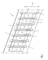
- Fig. 1 is shown in a perspective view of an interposer belt 1, as it can be used in the device according to the invention.
- the interposer belt 1 has a series-arranged interposer 2 with a length dimension 2a, wherein the interposer show two contact adhesive surfaces 3 on the left and right sides. Between the contact adhesive surfaces 3 components 4 are arranged.
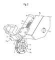
- Fig. 2 is shown in a perspective view of the device according to the invention.
- the interposer belt 1 is on a feed unit 8 with a surface 8a along the direction of the arrow 9 intermittently moved by means of engaging webs 10 in the direction of a cutting device 12 cyclically.
- a pressure stamp presses from above for fixing during the cutting process onto the interposer belt As soon as the interposer belt 1 has covered the path length of a module bridge width, a pressure stamp presses from above for fixing during the cutting process onto the interposer belt.
- a displacement of a cutting blade 13 or of cutting rollers takes place, as indicated by the double arrow 13a.
- the downwardly moving cutting blade 13 separates the protruding interposer from the interposer belt 1.
- the cutting blade 13 is formed such that it only cuts through the edge arranged holding webs 7 of the interposer belt 1.
- the remaining band area between the interposers has already been severed during the perforation process. In this way, the required cutting forces are reduced.
- the cutter blade 13 continues to move downwardly while tilting the entire cutter 12 with respect to the placement wheel to thereby create a gap between the rest of the interposer belt and the cut off interposer.
- the cutting blades are designed such that the cutting forces act during the separation process of the retaining webs 7 inwards, ie to the center of the tape, so as to avoid burring on the outer edge of the interposer.
- An insertion wheel 14 receives on its peripheral edge side 14 a the isolated Interposer 2 by means of Mit videkrallen and rotates about an axis 15th
- the placement wheel 14 has a width which is less than the gap between the two-part cutting blades, so that during the cutting process and the tilting operation, the cutting blades 13 are moved past the loading wheel 14 on the right and left.
- Fig. 3 is in a plan view the in Fig. 2 shown embodiment of the device shown.
- the Be Glaerrad has in predetermined sections on its peripheral edge side Mit videkrallen 16, which serve to fix the Interposer 2 on the Be Glaerrad.
- Mit videkrallen are equipped with a spring element and are used to take over the isolated Interposer after their separation from the Interposerband. 1
- the width of the placement wheel 14 corresponds to a length dimension 2 a of an interposer, preferably a length dimension of the transport edge 5.
- the placement wheel 14 has two edge-surrounding webs 18 and 19, on which the interposer rest. Recesses are arranged between these webs, which serve to receive the arranged on the Interposem components.
- the webs 18, 19 can be used as pressing elements for the fixation of attachment points 17, which correspond to the adhesive surfaces 3, on the moving support element.
- Fig. 4 is shown in a perspective view of the Be Publishedungsrad with a braking device for the device according to the invention.
- the brake device 20 has a brake pad 21 which is formed complementary to the peripheral edge side 14a of the mounting wheel 14.
- a heating element 22 is installed in the braking device, which activates the adhesive surface 3 at an attachment point 17 of the interposer 2 by heat conduction or thermal radiation.
- the interposer 2 is deposited on the support element and fixed by means of a counter-roller 24 by pressure and activation of the adhesive surfaces.
- Fig. 5 the braking device with the interposer belt 1 is shown in a perspective view.
- the brake pad 21 has left and right side brake pads 25 and 26, against the pressing elements 27 and 28, which are mounted on the placement press. Between the pressing elements 27, 28 and the brake pads 25, 26th are the Interposer 2 clamped in aligned position.
- Fig. 6 is shown in a perspective view of another embodiment of the invention. As can be seen from this illustration, the placement wheel 14 is coupled to a belt 29 which handles the transport of the singulated interposers.
- the fixation of the individual interposer between the counter-roller 24 and the placement wheel 14 is such that the pressure on the adhesive-adherent attachment points 17 and thus a prefixing is achieved by the individual interposer in a gap between the lying on the counter-roller 24 support member 23 and the Webs 18, 19 of the mounting wheel 14 is pushed.
- the gap is adjustable; whereby a contact pressure on the Interposer is changeable. It should be noted that the interposer is not pushed into the gap until it has been accelerated by means of the placement wheel. This prevents slippage between the interposer and the support element 23.
Landscapes
- Engineering & Computer Science (AREA)
- Condensed Matter Physics & Semiconductors (AREA)
- General Physics & Mathematics (AREA)
- Manufacturing & Machinery (AREA)
- Computer Hardware Design (AREA)
- Microelectronics & Electronic Packaging (AREA)
- Power Engineering (AREA)
- Physics & Mathematics (AREA)
- Folding Of Thin Sheet-Like Materials, Special Discharging Devices, And Others (AREA)
- Coupling Device And Connection With Printed Circuit (AREA)
- Special Conveying (AREA)
- Wire Bonding (AREA)
- Braking Arrangements (AREA)
- Perforating, Stamping-Out Or Severing By Means Other Than Cutting (AREA)
- Waveguide Aerials (AREA)
- Container, Conveyance, Adherence, Positioning, Of Wafer (AREA)
- Basic Packing Technique (AREA)
Claims (18)
- Dispositif pour séparer des ponts modules (2) agencés en bande de ponts modules (1) ou en assemblage de ponts modules et pour positionner les ponts modules séparés (2) sur un élément d'appui (23),
caractérisé par
un dispositif de séparation (11, 12, 13) pour séparer la bande de ponts modules (1) au niveau de ses zones de bord (7) entre, respectivement, deux ponts modules (2) et une roue d'équipement (14) pour la réception séparée et le transport sans glissement des ponts modules séparés (2) sur son rebord périphérique (14a) et pour le dépôt des ponts modules (2) sur l'élément d'appui mobile (23) après un mouvement de rotation exécuté par la roue d'équipement (14) autour d'un axe (15) dirigé parallèlement au plan des ponts modules. - Dispositif selon la revendication 1,
caractérisé en ce que
la roue d'équipement (14) présente sur son rebord périphérique (14a) des griffes d'entraînement (16) espacées l'une de l'autre et sollicitées par un ressort pour arrêter et entraîner des ponts modules individuels (2) sur le rebord périphérique (14a) . - Dispositif selon la revendication 1 ou 2,
caractérisé en ce que
la roue d'équipement (14) présente, sur son rebord périphérique (14a), une dimension en largeur qui correspond à une dimension en longueur (2a) d'un pont module (2). - Dispositif selon l'une quelconque des revendications précédentes,
caractérisé en ce que
la roue d'équipement (14) présente, sur son rebord périphérique (14a), au moins dans la zone où sont reçus les ponts modules (2), entre une arête (18, 19) agencée côté gauche et une arête agencée côté droit (18, 19) des évidements pour recevoir des composants (4) aménagés sur les ponts modules (2). - Dispositif selon l'une quelconque des revendications précédentes,
caractérisé en ce que
le dispositif de séparation (11, 12, 13) présente une lame de coupe (13) pouvant se déplacer perpendiculairement au plan de la bande de ponts modules ou des rouleaux de coupe pour séparer la bande de ponts modules (8) au niveau de ses zones de bord (7). - Dispositif selon la revendication 5,
caractérisé en ce que
le dispositif de séparation (11, 12, 13) est relié à une unité d'acheminement (8) pour acheminer la bande de ponts modules (1) à la lame de coupe (13). - Dispositif selon la revendication 6,
caractérisé en ce que
le dispositif de séparation (11, 12, 13) présente un vérin presseur (11) pour presser la bande de ponts modules (1) sur une surface (8a) de l'unité d'acheminement (8) pendant une opération de séparation. - Dispositif selon la revendication 6 ou 7,
caractérisé en ce que
l'unité d'acheminement (8) présente des éléments de guidage pour le guidage latéral de la bande de ponts modules. - Dispositif selon l'une quelconque des revendications 6 à 8,
caractérisé en ce que
l'unité d'acheminement (8) présente des éléments à complémentarité de forme (10) pour s'engager dans des ouvertures de passage (6) de la bande de ponts modules (1). - Dispositif selon l'une quelconque des revendications précédentes,
caractérisé en ce que
le dispositif de séparation (11, 12, 13) peut basculer pendant une opération de séparation par rapport à la roue d'équipement (14). - Dispositif selon l'une quelconque des revendications précédentes,
caractérisé en ce que,
entre le dispositif de séparation (11, 12, 13) et l'élément d'appui (23), est aménagé un dispositif de freinage (20), s'appliquant sur une partie du rebord périphérique (14a) de la roue d'équipement (14), pour freiner la roue d'équipement (14) en rotation. - Dispositif selon la revendication 11,
caractérisé en ce que
la roue d'équipement (14) peut être accélérée sous l'effet du dispositif de freinage (20) et d'un moteur à une vitesse de rotation, dont la vitesse périphérique correspond à une vitesse de l'élément d'appui (23) en mouvement. - Dispositif selon la revendication 11 ou 12,
caractérisé en ce que
le dispositif de freinage (20) contient un élément chauffant (22) pour chauffer les points adhésifs de contact (3) des ponts modules (2). - Dispositif selon l'une quelconque des revendications 11 à 13,
caractérisé en ce que
le dispositif de freinage (20) présente des éléments de guidage sur un sabot de frein (21) s'appliquant sur le rebord périphérique (14a) de la roue d'équipement (14) pour guider latéralement les ponts modules (2) pendant le mouvement de rotation de la roue d'équipement (14). - Dispositif selon la revendication 14,
caractérisé en ce que
le sabot de frein (21) présente deux garnitures de frein (25, 26) s'étendant sur le bord, contre lesquelles deux éléments de pression (27, 28) conformés de manière complémentaire et agencés sur le rebord périphérique (14a) exercent une pression, les ponts modules (2) étant disposés entre les éléments de pression (27, 28) et les garnitures de frein (25, 26). - Dispositif selon l'une quelconque des revendications précédentes,
caractérisé par
un contre-rouleau (24), qui est agencé pour fixer les ponts modules (2) sur l'élément d'appui (23), sur un côté de l'élément d'appui (23) opposé à la roue d'équipement (14). - Dispositif selon l'une quelconque des revendications précédentes,
caractérisé par
un dispositif de perforation pour perforer la bande de ponts modules (1) de sorte que les ponts modules (2), à l'exception de la zone de bord (7) de la bande de ponts modules (1), soient séparés l'un de l'autre pour minimiser une force de coupe du dispositif de séparation (11, 12, 13). - Dispositif selon la revendication 17,
caractérisé en ce que
le dispositif de perforation convient pour créer des arêtes de corps intercalaires définies pour permettre le transport précis sans glissement des corps intercalaires séparés.
Applications Claiming Priority (2)
| Application Number | Priority Date | Filing Date | Title |
|---|---|---|---|
| DE102004015994A DE102004015994B9 (de) | 2004-04-01 | 2004-04-01 | Vorrichtung zur Vereinzelung und Positionierung von Modulbrücken |
| PCT/EP2005/051353 WO2005096349A1 (fr) | 2004-04-01 | 2005-03-24 | Dispositif de separation et de positionnement de ponts modules |
Publications (2)
| Publication Number | Publication Date |
|---|---|
| EP1730767A1 EP1730767A1 (fr) | 2006-12-13 |
| EP1730767B1 true EP1730767B1 (fr) | 2009-09-23 |
Family
ID=34964668
Family Applications (1)
| Application Number | Title | Priority Date | Filing Date |
|---|---|---|---|
| EP05733613A Not-in-force EP1730767B1 (fr) | 2004-04-01 | 2005-03-24 | Dispositif de separation et de positionnement de ponts modules |
Country Status (8)
| Country | Link |
|---|---|
| US (1) | US20070209125A1 (fr) |
| EP (1) | EP1730767B1 (fr) |
| JP (1) | JP2007531295A (fr) |
| CN (1) | CN1950927A (fr) |
| AT (1) | ATE443924T1 (fr) |
| DE (2) | DE102004015994B9 (fr) |
| IL (1) | IL178146A0 (fr) |
| WO (1) | WO2005096349A1 (fr) |
Families Citing this family (6)
| Publication number | Priority date | Publication date | Assignee | Title |
|---|---|---|---|---|
| EP2264650B1 (fr) | 2003-07-07 | 2014-02-26 | Avery Dennison Corporation | Dispositif RFID à caractéristiques modifiables |
| US7500307B2 (en) | 2004-09-22 | 2009-03-10 | Avery Dennison Corporation | High-speed RFID circuit placement method |
| US7555826B2 (en) | 2005-12-22 | 2009-07-07 | Avery Dennison Corporation | Method of manufacturing RFID devices |
| US7154283B1 (en) | 2006-02-22 | 2006-12-26 | Avery Dennison Corporation | Method of determining performance of RFID devices |
| US7812731B2 (en) | 2006-12-22 | 2010-10-12 | Vigilan, Incorporated | Sensors and systems for detecting environmental conditions or changes |
| US8502684B2 (en) | 2006-12-22 | 2013-08-06 | Geoffrey J. Bunza | Sensors and systems for detecting environmental conditions or changes |
Family Cites Families (15)
| Publication number | Priority date | Publication date | Assignee | Title |
|---|---|---|---|---|
| DE3407234A1 (de) * | 1984-02-28 | 1985-08-29 | Georg 8411 Zeitlarn Sillner | Verfahren zum aufgurten von unterschiedlichen elektrischen bauelementen auf einen gemeinsamen gurt sowie vorrichtung zum durchfuehren dieses verfahrens |
| DE8807239U1 (fr) * | 1988-06-03 | 1988-11-03 | Fritsch, Adalbert, 8455 Kastl, De | |
| DE3903865C1 (en) * | 1989-02-10 | 1990-07-12 | Zevatech Ag, Bellach, Ch | Supply unit for components packed in belts for feeding automatic fitting machines |
| GB2250496B (en) * | 1990-12-04 | 1994-07-27 | Nitto Kogyo Kk | Automatic chip separating and feeding apparatus |
| JP2002037211A (ja) * | 2000-07-24 | 2002-02-06 | Ueno Seiki Kk | 電子部品用自動ハンドリング装置 |
| DE10038163A1 (de) * | 2000-08-04 | 2002-02-14 | Infineon Technologies Ag | Vorrichtung und Verfahren zur Bestückung von Transportgurten |
| US6893528B2 (en) * | 2000-11-01 | 2005-05-17 | Adalis Corporation | Web material advance system for web material applicator |
| US6456063B1 (en) * | 2000-11-03 | 2002-09-24 | Delphi Technologies, Inc. | Self compensating control circuit for digital magnetic sensors |
| US6951596B2 (en) * | 2002-01-18 | 2005-10-04 | Avery Dennison Corporation | RFID label technique |
| JP2003006596A (ja) * | 2001-06-25 | 2003-01-10 | Navitas Co Ltd | データキャリアシートの製造装置 |
| JP4011866B2 (ja) * | 2001-07-05 | 2007-11-21 | 株式会社 東京ウエルズ | 電子部品の分離・搬送装置及び分離・搬送方法 |
| DE10136359C2 (de) * | 2001-07-26 | 2003-06-12 | Muehlbauer Ag | Verfahren zum Verbinden von Mikrochipmodulen mit auf einem ersten Trägerband angeordneten Antennen zum Herstellen eines Transponders |
| US6821348B2 (en) * | 2002-02-14 | 2004-11-23 | 3M Innovative Properties Company | In-line deposition processes for circuit fabrication |
| US6982190B2 (en) * | 2003-03-25 | 2006-01-03 | Id Solutions, Inc. | Chip attachment in an RFID tag |
| US7242996B2 (en) * | 2003-03-25 | 2007-07-10 | Id Solutions, Inc. | Attachment of RFID modules to antennas |
-
2004
- 2004-04-01 DE DE102004015994A patent/DE102004015994B9/de not_active Expired - Fee Related
-
2005
- 2005-03-24 EP EP05733613A patent/EP1730767B1/fr not_active Not-in-force
- 2005-03-24 US US10/594,938 patent/US20070209125A1/en not_active Abandoned
- 2005-03-24 WO PCT/EP2005/051353 patent/WO2005096349A1/fr active Application Filing
- 2005-03-24 JP JP2007505548A patent/JP2007531295A/ja active Pending
- 2005-03-24 CN CNA2005800090257A patent/CN1950927A/zh active Pending
- 2005-03-24 AT AT05733613T patent/ATE443924T1/de not_active IP Right Cessation
- 2005-03-24 DE DE502005008183T patent/DE502005008183D1/de active Active
-
2006
- 2006-09-18 IL IL178146A patent/IL178146A0/en unknown
Also Published As
| Publication number | Publication date |
|---|---|
| IL178146A0 (en) | 2006-12-31 |
| JP2007531295A (ja) | 2007-11-01 |
| CN1950927A (zh) | 2007-04-18 |
| DE502005008183D1 (de) | 2009-11-05 |
| US20070209125A1 (en) | 2007-09-13 |
| ATE443924T1 (de) | 2009-10-15 |
| WO2005096349A1 (fr) | 2005-10-13 |
| DE102004015994A1 (de) | 2005-11-03 |
| DE102004015994B4 (de) | 2006-05-18 |
| EP1730767A1 (fr) | 2006-12-13 |
| DE102004015994B9 (de) | 2006-09-07 |
Similar Documents
| Publication | Publication Date | Title |
|---|---|---|
| EP1730767B1 (fr) | Dispositif de separation et de positionnement de ponts modules | |
| DE3430739C2 (de) | Verfahren zum Schneiden und Ausstanzen sowie Zuführen von Aufklebern verschiedener Formen | |
| EP1751005B1 (fr) | Procede et dispositif d'emballage d'objets plats | |
| EP0983579B1 (fr) | Procede et dispositif pour la production d'une etiquette multicouche | |
| EP3702169B1 (fr) | Procédé de fabrication d'un demi-produit ainsi que demi-produit | |
| DE102008000036B4 (de) | Verfahren zum Anfertigen histologischer Schnitte und Mikrotom mit einer Aufbring- und Schneideinrichtung | |
| EP2144833B1 (fr) | Procédé et dispositif d'application de bandes | |
| EP3741528B1 (fr) | Dispositif de revêtement d'une surface et méthode de revêtement d'une surface | |
| EP0999015B1 (fr) | Dispositif à bande sans fin équipé d'un système intégré de coupe pour imprimantes rotatives | |
| DE2414262C3 (de) | Verfahren und Vorrichtung zum Herstellen eines Nagelstreifens | |
| EP3515721B1 (fr) | Dispositif et procédé de séparation et de tri de pages doubles pour document d'identité, de valeur ou de sécurité en forme de livre, procédé et système de fabrication d'un document d'identité, de valeur ou de sécurité en forme de livre | |
| DE2639216C2 (de) | Verfahren und Vorrichtung zum Abtrennen von Zuschnitten für Zigarettenpackungen oder dgl. vom vorderen Ende einer fortlaufenden Materialbahn | |
| EP3556567B1 (fr) | Procédé et dispositif d'application d'une section de feuille adhésive séparée d'une bande adhésive à une couverture de livre | |
| EP1030075B1 (fr) | Méthode et appareil pour l'application de segments de garniture de friction par collage à une bague de support | |
| EP2248721A1 (fr) | Dispositif et procédé d'emballage d'objets | |
| EP1623368B1 (fr) | Dispositif et procede permettant de relier des modules micropuce avec des antennes | |
| DE19624277A1 (de) | Vorrichtung zum Schneiden von Papierbahnen | |
| EP3670206B1 (fr) | Dispositif et procédé d'application d'une couche adhésive à une couverture sans adhésif d'un document d'identification, de valeur ou de sécurité | |
| DE3433381C2 (fr) | ||
| EP0250709B1 (fr) | Procédé et dispositif d'assemblage et de fixation de bandes de liasses de formulaires | |
| CH637059A5 (de) | Kantenanleimmaschine. | |
| DE19948955B4 (de) | Bahnschneidvorrichtung mit einer integrierten Messeranordnung in einer Rollenrotationsdruckmaschine | |
| WO2020030771A1 (fr) | Dispositif pour la découpe et le retrait de fils de cerclage | |
| EP2103398B1 (fr) | Dispositif et procédé de coupe de produits d'impression pliés | |
| DE2640476A1 (de) | Vorrichtung zum zusammenhaengen von bandfoermigen abschnitten |
Legal Events
| Date | Code | Title | Description |
|---|---|---|---|
| PUAI | Public reference made under article 153(3) epc to a published international application that has entered the european phase |
Free format text: ORIGINAL CODE: 0009012 |
|
| 17P | Request for examination filed |
Effective date: 20061019 |
|
| AK | Designated contracting states |
Kind code of ref document: A1 Designated state(s): AT BE BG CH CY CZ DE DK EE ES FI FR GB GR HU IE IS IT LI LT LU MC NL PL PT RO SE SI SK TR |
|
| DAX | Request for extension of the european patent (deleted) | ||
| GRAP | Despatch of communication of intention to grant a patent |
Free format text: ORIGINAL CODE: EPIDOSNIGR1 |
|
| GRAS | Grant fee paid |
Free format text: ORIGINAL CODE: EPIDOSNIGR3 |
|
| GRAA | (expected) grant |
Free format text: ORIGINAL CODE: 0009210 |
|
| AK | Designated contracting states |
Kind code of ref document: B1 Designated state(s): AT BE BG CH CY CZ DE DK EE ES FI FR GB GR HU IE IS IT LI LT LU MC NL PL PT RO SE SI SK TR |
|
| REG | Reference to a national code |
Ref country code: GB Ref legal event code: FG4D Free format text: NOT ENGLISH |
|
| REG | Reference to a national code |
Ref country code: CH Ref legal event code: EP Ref country code: CH Ref legal event code: NV Representative=s name: ROTTMANN, ZIMMERMANN + PARTNER AG |
|
| REG | Reference to a national code |
Ref country code: IE Ref legal event code: FG4D |
|
| REF | Corresponds to: |
Ref document number: 502005008183 Country of ref document: DE Date of ref document: 20091105 Kind code of ref document: P |
|
| PG25 | Lapsed in a contracting state [announced via postgrant information from national office to epo] |
Ref country code: LT Free format text: LAPSE BECAUSE OF FAILURE TO SUBMIT A TRANSLATION OF THE DESCRIPTION OR TO PAY THE FEE WITHIN THE PRESCRIBED TIME-LIMIT Effective date: 20090923 Ref country code: SE Free format text: LAPSE BECAUSE OF FAILURE TO SUBMIT A TRANSLATION OF THE DESCRIPTION OR TO PAY THE FEE WITHIN THE PRESCRIBED TIME-LIMIT Effective date: 20090923 |
|
| LTIE | Lt: invalidation of european patent or patent extension |
Effective date: 20090923 |
|
| PG25 | Lapsed in a contracting state [announced via postgrant information from national office to epo] |
Ref country code: PL Free format text: LAPSE BECAUSE OF FAILURE TO SUBMIT A TRANSLATION OF THE DESCRIPTION OR TO PAY THE FEE WITHIN THE PRESCRIBED TIME-LIMIT Effective date: 20090923 Ref country code: SI Free format text: LAPSE BECAUSE OF FAILURE TO SUBMIT A TRANSLATION OF THE DESCRIPTION OR TO PAY THE FEE WITHIN THE PRESCRIBED TIME-LIMIT Effective date: 20090923 |
|
| PG25 | Lapsed in a contracting state [announced via postgrant information from national office to epo] |
Ref country code: CY Free format text: LAPSE BECAUSE OF FAILURE TO SUBMIT A TRANSLATION OF THE DESCRIPTION OR TO PAY THE FEE WITHIN THE PRESCRIBED TIME-LIMIT Effective date: 20090923 |
|
| REG | Reference to a national code |
Ref country code: IE Ref legal event code: FD4D |
|
| PG25 | Lapsed in a contracting state [announced via postgrant information from national office to epo] |
Ref country code: CZ Free format text: LAPSE BECAUSE OF FAILURE TO SUBMIT A TRANSLATION OF THE DESCRIPTION OR TO PAY THE FEE WITHIN THE PRESCRIBED TIME-LIMIT Effective date: 20090923 Ref country code: RO Free format text: LAPSE BECAUSE OF FAILURE TO SUBMIT A TRANSLATION OF THE DESCRIPTION OR TO PAY THE FEE WITHIN THE PRESCRIBED TIME-LIMIT Effective date: 20090923 Ref country code: ES Free format text: LAPSE BECAUSE OF FAILURE TO SUBMIT A TRANSLATION OF THE DESCRIPTION OR TO PAY THE FEE WITHIN THE PRESCRIBED TIME-LIMIT Effective date: 20100103 Ref country code: EE Free format text: LAPSE BECAUSE OF FAILURE TO SUBMIT A TRANSLATION OF THE DESCRIPTION OR TO PAY THE FEE WITHIN THE PRESCRIBED TIME-LIMIT Effective date: 20090923 Ref country code: PT Free format text: LAPSE BECAUSE OF FAILURE TO SUBMIT A TRANSLATION OF THE DESCRIPTION OR TO PAY THE FEE WITHIN THE PRESCRIBED TIME-LIMIT Effective date: 20100125 Ref country code: IE Free format text: LAPSE BECAUSE OF FAILURE TO SUBMIT A TRANSLATION OF THE DESCRIPTION OR TO PAY THE FEE WITHIN THE PRESCRIBED TIME-LIMIT Effective date: 20090923 Ref country code: IS Free format text: LAPSE BECAUSE OF FAILURE TO SUBMIT A TRANSLATION OF THE DESCRIPTION OR TO PAY THE FEE WITHIN THE PRESCRIBED TIME-LIMIT Effective date: 20100123 |
|
| PG25 | Lapsed in a contracting state [announced via postgrant information from national office to epo] |
Ref country code: SK Free format text: LAPSE BECAUSE OF FAILURE TO SUBMIT A TRANSLATION OF THE DESCRIPTION OR TO PAY THE FEE WITHIN THE PRESCRIBED TIME-LIMIT Effective date: 20090923 |
|
| PGFP | Annual fee paid to national office [announced via postgrant information from national office to epo] |
Ref country code: FI Payment date: 20100324 Year of fee payment: 6 Ref country code: FR Payment date: 20100330 Year of fee payment: 6 |
|
| PG25 | Lapsed in a contracting state [announced via postgrant information from national office to epo] |
Ref country code: DK Free format text: LAPSE BECAUSE OF FAILURE TO SUBMIT A TRANSLATION OF THE DESCRIPTION OR TO PAY THE FEE WITHIN THE PRESCRIBED TIME-LIMIT Effective date: 20090923 |
|
| PLBE | No opposition filed within time limit |
Free format text: ORIGINAL CODE: 0009261 |
|
| STAA | Information on the status of an ep patent application or granted ep patent |
Free format text: STATUS: NO OPPOSITION FILED WITHIN TIME LIMIT |
|
| PGFP | Annual fee paid to national office [announced via postgrant information from national office to epo] |
Ref country code: DE Payment date: 20100325 Year of fee payment: 6 Ref country code: NL Payment date: 20100324 Year of fee payment: 6 |
|
| 26N | No opposition filed |
Effective date: 20100624 |
|
| BERE | Be: lapsed |
Owner name: MUHLBAUER A.G. Effective date: 20100331 |
|
| PG25 | Lapsed in a contracting state [announced via postgrant information from national office to epo] |
Ref country code: MC Free format text: LAPSE BECAUSE OF NON-PAYMENT OF DUE FEES Effective date: 20100331 Ref country code: GR Free format text: LAPSE BECAUSE OF FAILURE TO SUBMIT A TRANSLATION OF THE DESCRIPTION OR TO PAY THE FEE WITHIN THE PRESCRIBED TIME-LIMIT Effective date: 20091224 |
|
| REG | Reference to a national code |
Ref country code: CH Ref legal event code: PL |
|
| GBPC | Gb: european patent ceased through non-payment of renewal fee |
Effective date: 20100324 |
|
| PG25 | Lapsed in a contracting state [announced via postgrant information from national office to epo] |
Ref country code: BE Free format text: LAPSE BECAUSE OF NON-PAYMENT OF DUE FEES Effective date: 20100331 Ref country code: CH Free format text: LAPSE BECAUSE OF NON-PAYMENT OF DUE FEES Effective date: 20100331 Ref country code: LI Free format text: LAPSE BECAUSE OF NON-PAYMENT OF DUE FEES Effective date: 20100331 |
|
| PG25 | Lapsed in a contracting state [announced via postgrant information from national office to epo] |
Ref country code: IT Free format text: LAPSE BECAUSE OF FAILURE TO SUBMIT A TRANSLATION OF THE DESCRIPTION OR TO PAY THE FEE WITHIN THE PRESCRIBED TIME-LIMIT Effective date: 20090923 Ref country code: GB Free format text: LAPSE BECAUSE OF NON-PAYMENT OF DUE FEES Effective date: 20100324 |
|
| PG25 | Lapsed in a contracting state [announced via postgrant information from national office to epo] |
Ref country code: AT Free format text: LAPSE BECAUSE OF NON-PAYMENT OF DUE FEES Effective date: 20100324 |
|
| REG | Reference to a national code |
Ref country code: NL Ref legal event code: V1 Effective date: 20111001 |
|
| PG25 | Lapsed in a contracting state [announced via postgrant information from national office to epo] |
Ref country code: FI Free format text: LAPSE BECAUSE OF NON-PAYMENT OF DUE FEES Effective date: 20110324 |
|
| REG | Reference to a national code |
Ref country code: FR Ref legal event code: ST Effective date: 20111130 |
|
| PG25 | Lapsed in a contracting state [announced via postgrant information from national office to epo] |
Ref country code: NL Free format text: LAPSE BECAUSE OF NON-PAYMENT OF DUE FEES Effective date: 20111001 Ref country code: FR Free format text: LAPSE BECAUSE OF NON-PAYMENT OF DUE FEES Effective date: 20110331 Ref country code: DE Free format text: LAPSE BECAUSE OF NON-PAYMENT OF DUE FEES Effective date: 20111001 |
|
| REG | Reference to a national code |
Ref country code: DE Ref legal event code: R119 Ref document number: 502005008183 Country of ref document: DE Effective date: 20111001 |
|
| PG25 | Lapsed in a contracting state [announced via postgrant information from national office to epo] |
Ref country code: BG Free format text: LAPSE BECAUSE OF FAILURE TO SUBMIT A TRANSLATION OF THE DESCRIPTION OR TO PAY THE FEE WITHIN THE PRESCRIBED TIME-LIMIT Effective date: 20090923 Ref country code: LU Free format text: LAPSE BECAUSE OF NON-PAYMENT OF DUE FEES Effective date: 20100324 Ref country code: HU Free format text: LAPSE BECAUSE OF FAILURE TO SUBMIT A TRANSLATION OF THE DESCRIPTION OR TO PAY THE FEE WITHIN THE PRESCRIBED TIME-LIMIT Effective date: 20100324 |
|
| PG25 | Lapsed in a contracting state [announced via postgrant information from national office to epo] |
Ref country code: TR Free format text: LAPSE BECAUSE OF FAILURE TO SUBMIT A TRANSLATION OF THE DESCRIPTION OR TO PAY THE FEE WITHIN THE PRESCRIBED TIME-LIMIT Effective date: 20090923 |