EP1730767B1 - Device for separating and positioning module bridges - Google Patents
Device for separating and positioning module bridges Download PDFInfo
- Publication number
- EP1730767B1 EP1730767B1 EP05733613A EP05733613A EP1730767B1 EP 1730767 B1 EP1730767 B1 EP 1730767B1 EP 05733613 A EP05733613 A EP 05733613A EP 05733613 A EP05733613 A EP 05733613A EP 1730767 B1 EP1730767 B1 EP 1730767B1
- Authority
- EP
- European Patent Office
- Prior art keywords
- module
- bridges
- support element
- placement wheel
- peripheral edge
- Prior art date
- Legal status (The legal status is an assumption and is not a legal conclusion. Google has not performed a legal analysis and makes no representation as to the accuracy of the status listed.)
- Not-in-force
Links
Images


Classifications
-
- H—ELECTRICITY
- H01—ELECTRIC ELEMENTS
- H01L—SEMICONDUCTOR DEVICES NOT COVERED BY CLASS H10
- H01L21/00—Processes or apparatus adapted for the manufacture or treatment of semiconductor or solid state devices or of parts thereof
- H01L21/67—Apparatus specially adapted for handling semiconductor or electric solid state devices during manufacture or treatment thereof; Apparatus specially adapted for handling wafers during manufacture or treatment of semiconductor or electric solid state devices or components ; Apparatus not specifically provided for elsewhere
- H01L21/67005—Apparatus not specifically provided for elsewhere
- H01L21/67011—Apparatus for manufacture or treatment
- H01L21/67132—Apparatus for placing on an insulating substrate, e.g. tape
Definitions
- the invention relates to a device for separating module bridges arranged in a module bridge band or module bridge assembly and for positioning the isolated module bridges on a support element according to the preamble of claim 1.
- WO 03/012734 A1 discloses a method for connecting microchip modules with antennas arranged on a first carrier band for producing a transponder.
- Module bridges which are arranged as an interposer in the form of an interposer band or module bridge band arranged in rows, have hitherto been cut by means of a separating device such that the module bridges detached from the module bridge band isolated. Subsequently, the module bridges are positioned by means of a further device on a stationary support element and stored by a downward sliding movement of this device individually on the stopped support element. Alternatively, the positioning device may be held without downward movement above the support element while the support element moves by means of an upward sliding movement towards the retained module bridge.
- the support element After placing a module bridge on the support element, the support element is moved by a predetermined distance section in its direction in order to record at a new location another module bridge can.
- Such devices require the stopping of the support element during the storage of a module bridge on this. As a result, the throughput of a placement device, which includes such devices, reduced.
- the separate placement of the separation device and the positioning device requires reorienting the module bridge upon receipt of a detached module bridge by the positioning device.
- the present invention has for its object to provide a device for separating and a subsequent relative to a support element positioning positioning of module bridges from a module bridge band available that allows a higher throughput in a process of the assembly of module bridges.
- An essential point of the invention is that in a device for singling arranged in a module bridge band or module bridge composite module bridges and positioning of the isolated module bridges on a support element a separator for separating the module bridge band in the edge regions between each two module bridges and a placement wheel for isolated recording the separated module bridges is arranged at its peripheral edge side, wherein the placement wheel is provided for storing the module bridges on the moving support element after a rotary movement of the placement wheel about a parallel to the module bridge plane aligned axis.
- module bridge bands that are perforated so that they still have holding webs only in their edge areas between the module bridges are cut in a continuous workflow for separating the module bridges and then adjusted by the Be Partnerserrad whose rotational speed of a speed of the support element on the moving support element, which may for example be band-like, are stored.
- Such placement of the support element thus requires for the positioning of the module bridge no stopping of the support element, resulting in an increased throughput of a placement device.
- the perforated module bridge band between the module bridges has through openings, preferably holes, which serve for the engagement of pins or webs, for the transport of the module strap on a feeding unit towards the separator precise alignment of the module bridge band in the area of a cutting knife can be achieved. In this way, the arrangement of a conventional detection camera for aligning the module bridge band and the then isolated module bridges is unnecessary.
- the placement wheel on its peripheral edge side spaced apart, preferably spring-loaded trained as a driver locking elements for locking individual module bridges on the peripheral edge side.
- These locking elements also serve to align the isolated module bridges on the placement and against the support element on which they are finally stored.
- the placement wheel has at its peripheral edge side a width dimension corresponding to a length dimension of a module bridge, so that by means of additional guide elements which are arranged on a complementary to the peripheral edge side of the mounting wheel and applied to this brake pad of a braking device, a lateral guiding and at the same time aligning the module bridges during the rotational movement of the mounting wheel is possible.
- the placement wheel is designed such that it has on its peripheral edge side at least in the area in which the module bridges are accommodated between a left side and a right side arranged web recesses for receiving arranged on the module bridges components.
- damage to the components is excluded in a fly-up of the module bridges on the peripheral edge side.
- the separating device contains the cutting knife, which can be displaced perpendicularly to the module bridge belt plane, for severing the module bridge belt in its edge regions, after it has been cyclically fed via the feed unit by one path, which corresponds to the width of a module bridge, to the cutting blade.
- the separator has a plunger for pressing the module bridge strap on a surface of the feed unit.
- the feed unit may include guide elements for lateral guidance of the module bridge strap.
- the entire divider is tilted relative to the placement wheel during further forward movement of the cutting knife so as to provide a clearance between the remainder of the module bridgewire and the severed module bridge received by the placement wheel.
- the braking device in conjunction with a motor driving the placement wheel, ensures that the placement wheel, after receiving a module bridge, is accelerated to the rotational speed whose peripheral speed corresponds to the speed of the continuously moving support element.
- the braking device is additionally equipped with a heating element for heating Needlesklebestellen the module bridges, which are arranged on the mounting wheel, so that an arranged on the module bridges adhesive is activated to then enter into an adhesive bond with the support element.
- the brake pad preferably has two edge-extending brake pads, against which two complementary formed arranged on the peripheral edge side of the Be Industriesungsrades pressing elements can be pressed, wherein the module bridges are arranged between the pressing elements and the brake pads.
- a counter-roller is arranged on the mounting wheel opposite side of the support element, which presses against the placement wheel with intermediate support element and module bridge
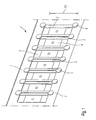
- Fig. 1 is shown in a perspective view of an interposer belt 1, as it can be used in the device according to the invention.
- the interposer belt 1 has a series-arranged interposer 2 with a length dimension 2a, wherein the interposer show two contact adhesive surfaces 3 on the left and right sides. Between the contact adhesive surfaces 3 components 4 are arranged.
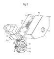
- Fig. 2 is shown in a perspective view of the device according to the invention.
- the interposer belt 1 is on a feed unit 8 with a surface 8a along the direction of the arrow 9 intermittently moved by means of engaging webs 10 in the direction of a cutting device 12 cyclically.
- a pressure stamp presses from above for fixing during the cutting process onto the interposer belt As soon as the interposer belt 1 has covered the path length of a module bridge width, a pressure stamp presses from above for fixing during the cutting process onto the interposer belt.
- a displacement of a cutting blade 13 or of cutting rollers takes place, as indicated by the double arrow 13a.
- the downwardly moving cutting blade 13 separates the protruding interposer from the interposer belt 1.
- the cutting blade 13 is formed such that it only cuts through the edge arranged holding webs 7 of the interposer belt 1.
- the remaining band area between the interposers has already been severed during the perforation process. In this way, the required cutting forces are reduced.
- the cutter blade 13 continues to move downwardly while tilting the entire cutter 12 with respect to the placement wheel to thereby create a gap between the rest of the interposer belt and the cut off interposer.
- the cutting blades are designed such that the cutting forces act during the separation process of the retaining webs 7 inwards, ie to the center of the tape, so as to avoid burring on the outer edge of the interposer.
- An insertion wheel 14 receives on its peripheral edge side 14 a the isolated Interposer 2 by means of Mit videkrallen and rotates about an axis 15th
- the placement wheel 14 has a width which is less than the gap between the two-part cutting blades, so that during the cutting process and the tilting operation, the cutting blades 13 are moved past the loading wheel 14 on the right and left.
- Fig. 3 is in a plan view the in Fig. 2 shown embodiment of the device shown.
- the Be Glaerrad has in predetermined sections on its peripheral edge side Mit videkrallen 16, which serve to fix the Interposer 2 on the Be Glaerrad.
- Mit videkrallen are equipped with a spring element and are used to take over the isolated Interposer after their separation from the Interposerband. 1
- the width of the placement wheel 14 corresponds to a length dimension 2 a of an interposer, preferably a length dimension of the transport edge 5.
- the placement wheel 14 has two edge-surrounding webs 18 and 19, on which the interposer rest. Recesses are arranged between these webs, which serve to receive the arranged on the Interposem components.
- the webs 18, 19 can be used as pressing elements for the fixation of attachment points 17, which correspond to the adhesive surfaces 3, on the moving support element.
- Fig. 4 is shown in a perspective view of the Be Publishedungsrad with a braking device for the device according to the invention.
- the brake device 20 has a brake pad 21 which is formed complementary to the peripheral edge side 14a of the mounting wheel 14.
- a heating element 22 is installed in the braking device, which activates the adhesive surface 3 at an attachment point 17 of the interposer 2 by heat conduction or thermal radiation.
- the interposer 2 is deposited on the support element and fixed by means of a counter-roller 24 by pressure and activation of the adhesive surfaces.
- Fig. 5 the braking device with the interposer belt 1 is shown in a perspective view.
- the brake pad 21 has left and right side brake pads 25 and 26, against the pressing elements 27 and 28, which are mounted on the placement press. Between the pressing elements 27, 28 and the brake pads 25, 26th are the Interposer 2 clamped in aligned position.
- Fig. 6 is shown in a perspective view of another embodiment of the invention. As can be seen from this illustration, the placement wheel 14 is coupled to a belt 29 which handles the transport of the singulated interposers.
- the fixation of the individual interposer between the counter-roller 24 and the placement wheel 14 is such that the pressure on the adhesive-adherent attachment points 17 and thus a prefixing is achieved by the individual interposer in a gap between the lying on the counter-roller 24 support member 23 and the Webs 18, 19 of the mounting wheel 14 is pushed.
- the gap is adjustable; whereby a contact pressure on the Interposer is changeable. It should be noted that the interposer is not pushed into the gap until it has been accelerated by means of the placement wheel. This prevents slippage between the interposer and the support element 23.
Landscapes
- Engineering & Computer Science (AREA)
- Physics & Mathematics (AREA)
- Condensed Matter Physics & Semiconductors (AREA)
- General Physics & Mathematics (AREA)
- Manufacturing & Machinery (AREA)
- Computer Hardware Design (AREA)
- Microelectronics & Electronic Packaging (AREA)
- Power Engineering (AREA)
- Folding Of Thin Sheet-Like Materials, Special Discharging Devices, And Others (AREA)
- Braking Arrangements (AREA)
- Container, Conveyance, Adherence, Positioning, Of Wafer (AREA)
- Special Conveying (AREA)
- Waveguide Aerials (AREA)
- Perforating, Stamping-Out Or Severing By Means Other Than Cutting (AREA)
- Coupling Device And Connection With Printed Circuit (AREA)
- Wire Bonding (AREA)
- Basic Packing Technique (AREA)
Abstract
Description
Die Erfindung betrifft eine Vorrichtung zur Vereinzelung von in einem Modulbrückenband oder Modulbrückenverbund angeordneten Modulbrücken und zur Positionierung der vereinzelten Modulbrücken auf einem Auflageelement gemäß dem Oberbegriff des Patentanspruches 1.The invention relates to a device for separating module bridges arranged in a module bridge band or module bridge assembly and for positioning the isolated module bridges on a support element according to the preamble of
Modulbrücken, die als Interposer in Form eines Interposerbandes beziehungsweise Modulbrückenbandes reihenartig angeordnet vorliegen, sind bisher mittels einer Trennvorrichtung derart geschnitten worden, dass sich die Modulbrücken aus dem Modulbrückenband vereinzelt herauslösten. Anschließend werden die Modulbrücken mittels einer weiteren Einrichtung über einem stehenden Auflageelement positioniert und durch eine abwärts gerichtete Verschiebebewegung dieser Einrichtung einzeln auf dem angehaltenen Auflageelement abgelegt. Alternativ kann die Positionierungseinrichtung ohne Abwärtsbewegung oberhalb des Auflageelementes gehalten werden, während sich das Auflageelement mittels einer Aufwärtsverschiebebewegung zu der festgehaltenen Modulbrücke hinbewegt.Module bridges, which are arranged as an interposer in the form of an interposer band or module bridge band arranged in rows, have hitherto been cut by means of a separating device such that the module bridges detached from the module bridge band isolated. Subsequently, the module bridges are positioned by means of a further device on a stationary support element and stored by a downward sliding movement of this device individually on the stopped support element. Alternatively, the positioning device may be held without downward movement above the support element while the support element moves by means of an upward sliding movement towards the retained module bridge.
Nach Ablegen einer Modulbrücke auf dem Auflageelement wird das Auflageelement um einen vorbestimmten Streckenabschnitt in seiner Laufrichtung weiterbewegt, um an einem neuen Ort eine weitere Modulbrücke aufnehmen zu können.After placing a module bridge on the support element, the support element is moved by a predetermined distance section in its direction in order to record at a new location another module bridge can.
Derartige Vorrichtungen erfordern das Anhalten des Auflageelementes während der Ablage einer Modulbrücke auf diesen. Dadurch wird der Durchsatz einer Bestückungsvorrichtung, die derartige Vorrichtungen beinhaltet, reduziert. Zudem erfordert das getrennte Anordnen von der Trennvorrichtung und der Positionierungsvorrichtung ein erneutes Ausrichten der Modulbrücke bei der Aufnahme einer abgetrennten Modulbrücke durch die Positionierungsvorrichtung.Such devices require the stopping of the support element during the storage of a module bridge on this. As a result, the throughput of a placement device, which includes such devices, reduced. In addition, the separate placement of the separation device and the positioning device requires reorienting the module bridge upon receipt of a detached module bridge by the positioning device.
Demzufolge liegt der vorliegenden Erfindung die Aufgabe zugrunde, eine Vorrichtung zur Vereinzelung und einer sich anschließenden gegenüber einem Auflageelement stattfindenden Positionierung von Modulbrücken aus einem Modulbrückenband zur Verfügung zu stellen, die einen höheren Durchsatz bei einem Vorgang des Bestückens von Modulbrücken ermögl icht.Accordingly, the present invention has for its object to provide a device for separating and a subsequent relative to a support element positioning positioning of module bridges from a module bridge band available that allows a higher throughput in a process of the assembly of module bridges.
Diese Aufgabe wird gemäß den Merkmalen des Patentanspruches 1 gelöst.This object is achieved according to the features of
Ein wesentlicher Punkt der Erfindung liegt darin, dass bei einer Vorrichtung zur Vereinzelung von in einem Modulbrückenband oder Modulbrückenverbund angeordneten Modulbrücken und zur Positionierung der vereinzelten Modulbrücken auf einem Auflageelement eine Trenneinrichtung zum Trennen des Modulbrückenbandes in dessen Randbereichen zwischen jeweils zwei Modulbrücken sowie ein Bestückungsrad zum vereinzelten Aufnehmen der abgetrennten Modulbrücken an dessen Umfangsrandseite angeordnet ist, wobei das Bestückungsrad zum Ablegen der Modulbrücken auf das sich bewegende Auflageelement nach einer durchgeführten Drehbewegung des Bestückungsrades um eine parallel zur Modulbrückenebene ausgerichtete Achse vorgesehen ist. Durch eine derartige Vorrichtung können Modulbrückenbänder, die derart perforiert sind, dass sie lediglich in ihren Randbereichen zwischen den Modulbrücken noch Haltestege aufweisen, in einem fortlaufenden Arbeitsablauf zur Vereinzelung der Modulbrücken geschnitten werden und anschließend durch das Bestückerrad, dessen Drehgeschwindigkeit einer Geschwindigkeit des Auflageelementes angepasst wird, auf dem sich bewegenden Auflageelement, welches beispielsweise bandartig ausgebildet sein kann, abgelegt werden. Eine solche Bestückung des Auflageelementes erfordert also für die Positionierung der Modulbrücke kein Anhalten des Auflageelementes, woraus sich ein erhöhter Durchsatz einer Bestückungsvorrichtung ergibt.An essential point of the invention is that in a device for singling arranged in a module bridge band or module bridge composite module bridges and positioning of the isolated module bridges on a support element a separator for separating the module bridge band in the edge regions between each two module bridges and a placement wheel for isolated recording the separated module bridges is arranged at its peripheral edge side, wherein the placement wheel is provided for storing the module bridges on the moving support element after a rotary movement of the placement wheel about a parallel to the module bridge plane aligned axis. By such a device module bridge bands that are perforated so that they still have holding webs only in their edge areas between the module bridges are cut in a continuous workflow for separating the module bridges and then adjusted by the Bestückerrad whose rotational speed of a speed of the support element on the moving support element, which may for example be band-like, are stored. Such placement of the support element thus requires for the positioning of the module bridge no stopping of the support element, resulting in an increased throughput of a placement device.
Da das perforierte Modulbrückenband zwischen den Modulbrücken Durchgangsöffnungen, vorzugsweise Löcher aufweist, die zum Eingreifen von Stiften oder Stegen, für den Transport des Modulbrückenbandes auf einer Zuführeinheit zu der Trenneinrichtung hin dienen, kann eine genaue Ausrichtung des Modulbrückenbandes im Bereich eines Schneidemessers erreicht werden. Auf diese Weise erübrigt sich die Anordnung einer bisher üblichen Erfassungskamera zur Ausrichtung des Modulbrückenbandes und der anschließend vereinzelten Modulbrücken.As the perforated module bridge band between the module bridges has through openings, preferably holes, which serve for the engagement of pins or webs, for the transport of the module strap on a feeding unit towards the separator precise alignment of the module bridge band in the area of a cutting knife can be achieved. In this way, the arrangement of a conventional detection camera for aligning the module bridge band and the then isolated module bridges is unnecessary.
Gemäß einer bevorzugten Ausführungsform weist das Bestückungsrad an seiner Umfangsrandseite voneinander beabstandete, vorzugsweise federbeaufschlagte als Mitnehmer ausgebildete Arretierungselemente zum Arretieren einzelner Modulbrücken auf der Umfangsrandseite auf. Diese Arretierungselemente dienen zudem zum Ausrichten der vereinzelten Modulbrücken auf dem Bestückungsrad und gegenüber dem Auflageelement, auf welchem sie abschließend abgelegt werden.According to a preferred embodiment, the placement wheel on its peripheral edge side spaced apart, preferably spring-loaded trained as a driver locking elements for locking individual module bridges on the peripheral edge side. These locking elements also serve to align the isolated module bridges on the placement and against the support element on which they are finally stored.
Das Bestückungsrad weist an seine Umfangsrandseite eine Breitenabmessung auf, die einer Längenabmessung einer Modulbrücke entspricht, sodass mittels zusätzlicher Führungselemente, die an einem komplementär zu der Umfangsrandseite des Bestückungsrades ausgebildeten und an dieser anliegenden Bremsklotz einer Bremseinrichtung angeordnet sind, ein seitliches Führen und zugleich Ausrichten der Modulbrücken während der Drehbewegung des Bestückungsrades möglich ist.The placement wheel has at its peripheral edge side a width dimension corresponding to a length dimension of a module bridge, so that by means of additional guide elements which are arranged on a complementary to the peripheral edge side of the mounting wheel and applied to this brake pad of a braking device, a lateral guiding and at the same time aligning the module bridges during the rotational movement of the mounting wheel is possible.
Vorzugsweise ist das Bestückungsrad derart ausgebildet, dass es an seiner Umfangsrandseite zumindestens in dem Bereich, in dem die Modulbrücken aufgenommen sind, zwischen einem linksseitig und einem rechtsseitig angeordneten Steg Ausnehmungen zur Aufnahme von auf den Modulbrücken angeordneten Bauelementen aufweist. Somit ist eine Beschädigung der Bauelemente bei einem Auffliegen der Modulbrücken auf der Umfangsrandseite ausgeschlossen.Preferably, the placement wheel is designed such that it has on its peripheral edge side at least in the area in which the module bridges are accommodated between a left side and a right side arranged web recesses for receiving arranged on the module bridges components. Thus, damage to the components is excluded in a fly-up of the module bridges on the peripheral edge side.
Die Trenneinrichtung beinhaltet das senkrecht zur Modulbrückenbandebene verschiebbare Schneidmesser zum Durchtrennen des Modulbrückenbandes in dessen Randbereichen, nachdem es über die Zuführeinheit taktweise um jeweils einen Weg, der der Breite einer Modulbrücke entspricht, dem Schneidmesser zugeführt worden ist.The separating device contains the cutting knife, which can be displaced perpendicularly to the module bridge belt plane, for severing the module bridge belt in its edge regions, after it has been cyclically fed via the feed unit by one path, which corresponds to the width of a module bridge, to the cutting blade.
Um einen sauberen Schnitt mittels des Schneidemessers ohne Verschieben des Modulbrückenbandes zu ermöglichen, weist die Trenneinrichtung einen Druckstempel zum Andrücken des Modulbrückenbandes auf eine Oberfläche der Zuführeinheit auf.In order to enable a clean cut by means of the Schneidemessers without moving the module bridge strap, the separator has a plunger for pressing the module bridge strap on a surface of the feed unit.
Zudem kann die Zuführeinheit Führungselemente zur seitlichen Führung des Modulbrückenbandes beinhalten.In addition, the feed unit may include guide elements for lateral guidance of the module bridge strap.
Nachdem das Schneidmesser das Modulbrückenband durchtrennt hat, wird die gesamte Trenneinrichtung während einer weiteren Vorwärtsbewegung des Schneidmessers gegenüber dem Bestückungsrad gekippt, sodass ein Abstand zwischen dem restlichen Modulbrückenband und der abgetrennten Modulbrücke, die von dem Bestückungsrad aufgenommen wird, geschaffen wird.After the cutting blade has severed the module bridgewire, the entire divider is tilted relative to the placement wheel during further forward movement of the cutting knife so as to provide a clearance between the remainder of the module bridgewire and the severed module bridge received by the placement wheel.
Zwischen der Trenneinrichtung und dem Auflageelement ist die an einem Teil der Umfangsrandseite des Bestückungsrades anliegende Bremseinrichtung mit dem Bremsklotz zum Bremsen des sich drehenden Bestückungsrades angeordnet. Die Bremseinrichtung sorgt im Zusammenspiel mit einem das Bestückungsrad antreibenden Motor dafür, dass das Bestückungsrad nach Aufnahme einer Modulbrücke auf die Drehgeschwindigkeit beschleunigt wird, deren Umfangsgeschwindigkeit der Geschwindigkeit des sich fortlaufend bewegenden Auflageelementes entspricht.Between the separator and the support member which abuts against a part of the peripheral edge side of the placement wheel brake device is arranged with the brake pad for braking the rotating placement wheel. The braking device, in conjunction with a motor driving the placement wheel, ensures that the placement wheel, after receiving a module bridge, is accelerated to the rotational speed whose peripheral speed corresponds to the speed of the continuously moving support element.
Die Bremseinrichtung ist zusätzlich mit einem Heizelement zum Erwärmen von Kontaktklebestellen der Modulbrücken, die auf dem Bestückungsrad angeordnet sind, ausgestattet, sodass ein auf den Modulbrücken angeordneter Klebstoff aktiviert wird, um anschließend mit dem Auflageelement eine Klebeverbindung einzugehen.The braking device is additionally equipped with a heating element for heating Kontaktklebestellen the module bridges, which are arranged on the mounting wheel, so that an arranged on the module bridges adhesive is activated to then enter into an adhesive bond with the support element.
Der Bremsklotz weist vorzugsweise zwei randseitig verlaufende Bremsbelege auf, gegen welche zwei komplementär ausgebildete auf der Umfangsrandseite des Bestückungsrades angeordnete Andrückelemente drückbar sind, wobei zwischen den Andrückelementen und den Bremsbelägen die Modulbrücken angeordnet sind. Somit ist eine zuverlässige zusätzliche Fixierung der auf dem Bestückungsrad vorhandenen Modulbrücken während seiner Drehbewegung möglich.The brake pad preferably has two edge-extending brake pads, against which two complementary formed arranged on the peripheral edge side of the Bestückungsrades pressing elements can be pressed, wherein the module bridges are arranged between the pressing elements and the brake pads. Thus, a reliable additional fixation of existing on the mounting wheel module bridges during its rotation is possible.
Um die einzelnen Modulbrücken auf dem Auflageelement zu fixieren, ist auf der dem Bestückungsrad entgegengesetzten Seite des Auflageelementes eine Gegenrolle angeordnet, die gegen das Bestückungsrad mit dazwischenliegendem Auflageelement und Modulbrücke drücktIn order to fix the individual module bridges on the support element, a counter-roller is arranged on the mounting wheel opposite side of the support element, which presses against the placement wheel with intermediate support element and module bridge
Weitere vorteilhafte Ausführungsformen ergeben sich aus den Unteransprüchen.Further advantageous embodiments will become apparent from the dependent claims.
Vorteile und Zweckmäßigkeiten sind der nachfolgenden Beschreibung in Verbindung mit der Zeichnung zu entnehmen. Hierbei zeigen:
- Fig. 1
- in einer perspektivischen Ansicht ein bereits perforiertes Interposerband zur Verwendung in einer erfindungsgemäßen Vorrichtung;
- Fig. 2
- in einer perspektivischen Ansicht eine Vorrichtung zum Vereinzeln und Positionieren von Modulbrücken gemäß einer Ausführungsform der Erfindung;
- Fig. 3
- in einer Draufsicht die in
Fig. 2 gezeigte Vorrichtung gemäß einer Ausführungsform der Erfindung; - Fig. 4
- in einer perspektivischen Ansicht ein Bestückungsrad mit einer Bremseinrichtung für die erfindungsgemäße Vorrichtung;
- Fig. 5
- in einer perspektivischen Ansicht eine Bremseinrichtung mit einem Interposerband für die erfindungsgemäße Vorrichtung;
- Fig. 6
- in einer perspektivischen Darstellung eine Vorrichtung gemäß einer weiteren Ausführungsform der Erfindung.
- Fig. 1
- in a perspective view an already perforated interposer tape for use in a device according to the invention;
- Fig. 2
- in a perspective view of an apparatus for separating and positioning of module bridges according to an embodiment of the invention;
- Fig. 3
- in a plan view the in
Fig. 2 shown device according to an embodiment of the invention; - Fig. 4
- in a perspective view of a loading wheel with a braking device for the device according to the invention;
- Fig. 5
- in a perspective view of a braking device with an interposer belt for the device according to the invention;
- Fig. 6
- in a perspective view of a device according to another embodiment of the invention.
In
Ein derartiges einreihiges Interposerband 1, welches auch als Mehrspurband ausgebildet sein kann, ist derart perforiert, dass es zwischen den Interposerschnitt und -transportkanten 5 Perforationslöcher 6 aufweist. Auf diese Weise bestehen in dem Randbereich des Interposerbandes 1 Haltestege 7, die die einzelnen Interposer 2 zu dem Interposerband 1 zusammenhalten.Such a single-
In
Anschließend findet eine Verschiebung eines Schneidemessers 13 bzw. von Schneidrollen statt, wie es durch den Doppelpfeil 13a angedeutet wird. Das sich nach unten bewegende Schneidemesser 13 trennt den hervorstehenden Interposer von dem Interposerband 1 ab. Hierfür ist das Schneidemesser 13 derart ausgebildet, dass es lediglich die randseitig angeordneten Haltestege 7 des Interposerbandes 1 durchtrennt. Der restliche Bandbereich zwischen den Interposem ist bereits während des Perforationsvorganges durchtrennt worden. Auf diese Weise verringern sich die aufzuwendenden Schnittkräfte.Subsequently, a displacement of a
Anschließend bewegt sich das Schneidemesser 13 weiterhin abwärts, während die gesamte Schneideeinrichtung 12 gegenüber dem Bestückungsrad gekippt wird, um auf diese Weise eine Lücke zwischen dem restlichen Interposerband und dem abgeschnittenen Interposer zu schaffen.Subsequently, the
Die Schneidmesser sind derart gestaltet, dass die Schnittkräfte während des Trennvorganges der Haltestege 7 nach innen, also zur Bandmitte hin wirken, um so eine Gratbildung am Außenrand des Interposers zu vermeiden.The cutting blades are designed such that the cutting forces act during the separation process of the retaining
Ein Bestückungsrad 14 nimmt an seiner Umfangsrandseite 14a den vereinzelten Interposer 2 mittels Mitnehmerkrallen auf und dreht sich um eine Achse 15.An
Das Bestückungsrad 14 weist eine Breite auf, die geringer als der Zwischenraum zwischen den zweitteilig ausgebildeten Schneidemessern ist, sodass während des Schneidvorganges und des Kippvorganges die Schneidemesser 13 rechts und links am Bestückungsrad vorbeibewegt 14 werden.The
In
Die Breite des Bestückungsrades 14 entspricht einer Längenabmessung 2a eines Interposers, vorzugsweise einer Längenabmessung der Transportkante 5.The width of the
Das Bestückungsrad 14 weist zwei randseitig umlaufende Stege 18 und 19 auf, auf welchen die Interposer aufliegen. Zwischen diesen Stegen sind Ausnehmungen angeordnet, die zur Aufnahme der auf den Interposem angeordneten Bauteile dienen.The
Die Stege 18, 19 können als Andrückelemente für die Fixierung von Befestigungspunkten 17, die den Klebeflächen 3 entsprechen, auf dem sich bewegenden Auflageelement verwendet werden.The
In
Sobald das Bestückungsrad 14 eine Drehgeschwindigkeit im Zusammenspiel mit der Bremseinrichtung 20 erreicht hat, die einer Geschwindigkeit eines Auflageelementes 23 entspricht, wird der Interposer 2 auf dem Auflageelement abgelegt und mittels einer Gegenrolle 24 durch Druck und Aktivierung der Klebeflächen fixiert.Once the
In
In
Für die exakte Fixierung der Interposer auf dem bewegten Ablageelement ist eine genaue Lagebestimmung in X- und Y-Richtung der Interposer erforderlich. Eine derartige Ausrichtung wird durch Bewegung an definierten Körperkanten des Interposers realisiert. Für die Fixierung in Y-Richtung sind seitliche Führungen an den Bremsklotz 21 montiert. Der einzelne Interposer wird mit der Mitnehmerkralle 16 am Bestückungsrad in X-Richtung transportiert, wobei die Mitnehmerkralle immer an der definierten Transportkante 5 des Interposers anliegen muss. Ein Verrutschen des Interposers wird dadurch verhindert, dass die Andrückelemente 27, 28 den Interposer gegen die Bremsbeläge 25, 26 drücken.For the exact fixation of the interposer on the moving storage element a precise position determination in the X and Y direction of the interposer is required. Such alignment is realized by movement at defined body edges of the interposer. For fixing in the Y direction lateral guides are mounted on the
Die Fixierung der einzelnen Interposer zwischen der Gegenrolle 24 und dem Bestückungsrad 14 erfolgt derart, dass der Druck auf die klebstoffhaftenden Befestigungspunkte 17 und somit eine Vorfixierung dadurch erreicht wird, indem der einzelne Interposer in einem Spalt zwischen dem auf der Gegenrolle 24 liegende Auflageelement 23 und den Stegen 18, 19 des Bestückungsrades 14 geschoben wird. Der Spalt ist einstellbar; wodurch eine Anpresskraft auf den Interposer veränderbar ist. Es ist zu beachten, dass der Interposer erst dann in den Spalt geschoben wird, nachdem er mittels des Bestückungsrads beschleunigt worden ist. Damit wird ein Schlupf zwischen den Interposer und dem Auflageelement 23 vermieden.The fixation of the individual interposer between the counter-roller 24 and the
Sämtliche in den Anmeldungsunterlagen offenbarten Merkmale werden als erfindungswesentlich beansprucht, sofern sie einzeln oder in Kombination gegenüber dem Stand der Technik neu sind.All disclosed in the application documents features are claimed as essential to the invention, provided they are new individually or in combination over the prior art.
- 11
- InterposerbandInterposer tape
- 22
- Interposerinterposer
- 2a2a
- Längsseite des InterposerLong side of the interposer
- 33
- Klebeflächen der InterposerAdhesive surfaces of the interposer
- 44
- Bauteilbereich des InterposersComponent area of the interposer
- 55
- Transportkante der InterposerTransport edge of the interposer
- 66
- Perforationslöcherperforation
- 77
- Haltestegeretaining webs
- 88th
- Zuführeinheitfeed
- 8a8a
- Oberfläche der ZuführeinheitSurface of the feed unit
- 99
- Transportrichtung des InterposerbandesTransport direction of the interposer belt
- 1010
- Stege, formschlüssige ElementeWebs, form-fitting elements
- 1111
- Druckstempelplunger
- 1212
- Schneideeinrichtungcutter
- 1313
- Schneidemesser, SchneidrollenCutting knife, cutting rollers
- 13a13a
- Verschieberichtung der SchneidemesserDisplacement direction of the cutting blades
- 1414
- Bestückungsradplacement wheel
- 14a14a
- Umfangsrandseite des BestückungsradesPeripheral edge side of the mounting wheel
- 1515
- Achseaxis
- 1616
- MitnehmerkralleMitnehmerkralle
- 1717
- Befestigungspunkte der InterposerAttachment points of the interposer
- 18, 1918, 19
- Stege des BestückungsradesWebs of the mounting wheel
- 2020
- Bremseinrichtungbraking means
- 2121
- Bremsklotzbrake pad
- 2222
- Heizelementheating element
- 2323
- Auflageelementsupport element
- 2424
- Gegenrollecounter-roller
- 25, 2625, 26
- Bremsbelegebrake pads
- 27,2827.28
- Andrückelementepressing elements
- 2929
- Bandtape
Claims (18)
- Device for separating module bridges (2) arranged in a module bridge strip (1) or module bridge set and for positioning the separated module bridges (2) on a support element (23), characterised by a dividing device (11, 12, 13) for dividing the module bridge strip (1) in the edge regions (7) thereof between in each case two module bridges (2), and a placement wheel (14) for separately receiving and transporting in a slip-free manner the separated module bridges (2) on its peripheral edge side (14a) and for depositing the module bridges (2) onto the moving support element (23) after a rotational movement of the placement wheel (14) has been carried out about an axis (15) oriented parallel to the module bridge plane.
- Device according to Claim 1, characterised in that the placement wheel (14) has, on its peripheral edge side (14a), spring-loaded carrier claws (16) which are spaced apart from one another and are provided for holding and carrying individual module bridges (2) on the peripheral edge side (14a).
- Device according to Claim 1 or 2, characterised in that the placement wheel (14) has, on its peripheral edge side (14a), a width dimension which corresponds to a length dimension (2a) of a module bridge (2).
- Device according to one of the preceding claims, characterised in that the placement wheel (14) has, on its peripheral edge side (14a), at least in the region in which the module bridges (2) are received, between a web (18, 19) arranged on the left side and on the right side, recesses for receiving components (4) arranged on the module bridges (2).
- Device according to one of the preceding claims, characterised in that the dividing device (11, 12, 13) has a cutting blade (13) or cutting rollers which can be displaced perpendicular to the plane of the module bridge strip and is/are provided for cutting through the module bridge strip (1) in the edge regions (7) thereof.
- Device according to Claim 5, characterised in that the dividing device (11, 12, 13) is connected to a feed unit (8) for feeding the module bridge strip (1) to the cutting blade (13).
- Device according to Claim 6, characterised in that the dividing device (11, 12, 13) has a pressure ram (11) for pressing the module bridge strip (1) against a surface (8a) of the feed unit (8) during a dividing operation.
- Device according to Claim 6 or 7, characterised in that the feed unit (8) has guide elements for laterally guiding the module bridge strip.
- Device according to one of Claims 6 to 8, characterised in that the feed unit (8) has form-fitting elements (10) for engaging in through-apertures (6) of the module bridge strip (1).
- Device according to one of the preceding claims, characterised in that the dividing device (11, 12, 13) can be tilted with respect to the placement wheel (14) during a dividing operation.
- Device according to one of the preceding claims, characterised in that a brake device (20) which bears against part of the peripheral edge side (14a) of the placement wheel (14) and is provided for braking the rotating placement wheel (14) is arranged between the dividing device (11, 12, 13) and the support element (23).
- Device according to Claim 11, characterised in that the placement wheel (14), under the effect of the brake device (20) and a motor, can be accelerated to a rotational speed at which the circumferential speed corresponds to a speed of the moving support element (23).
- Device according to Claim 11 or 12, characterised in that the brake device (20) includes a heating element (22) for heating contact adhesive points (3) on the module bridges (2).
- Device according to one of Claims 11 to 13, characterised in that the brake device (20) has, on a brake shoe (21) which bears against the peripheral edge side (14a) of the placement wheel (14), guide elements for laterally guiding the module bridges (2) during the rotational movement of the placement wheel (14).
- Device according to Claim 14, characterised in that the brake shoe (21) has two brake linings (25, 26) running along the edge, against which two pressing elements (27, 28) of complementary shape press, said pressing elements being arranged on the peripheral edge side (14a), wherein the module bridges (2) are arranged between the pressing elements (27, 28) and the brake linings (25, 26).
- Device according to one of the preceding claims, characterised by a counter-roller (24) which is arranged on a side of the support element (23) opposite the placement wheel (14) and is provided for fixing the module bridges (2) on the support element (23).
- Device according to one of the preceding claims, characterised by a perforation device for perforating the module bridge strip (1) in such a way that the module bridges (2) are separated from one another with the exception of the edge region (7) of the module bridge strip (1), in order to minimise a cutting force of the dividing device (11, 12, 13).
- Device according to Claim 17, characterised in that the perforation device is suitable for creating defined interposer edges for transporting the separated interposers in a slip-free and precise manner.
Applications Claiming Priority (2)
| Application Number | Priority Date | Filing Date | Title |
|---|---|---|---|
| DE102004015994A DE102004015994B9 (en) | 2004-04-01 | 2004-04-01 | Device for separating and positioning module bridges |
| PCT/EP2005/051353 WO2005096349A1 (en) | 2004-04-01 | 2005-03-24 | Device for separating and positioning module bridges |
Publications (2)
| Publication Number | Publication Date |
|---|---|
| EP1730767A1 EP1730767A1 (en) | 2006-12-13 |
| EP1730767B1 true EP1730767B1 (en) | 2009-09-23 |
Family
ID=34964668
Family Applications (1)
| Application Number | Title | Priority Date | Filing Date |
|---|---|---|---|
| EP05733613A Not-in-force EP1730767B1 (en) | 2004-04-01 | 2005-03-24 | Device for separating and positioning module bridges |
Country Status (8)
| Country | Link |
|---|---|
| US (1) | US20070209125A1 (en) |
| EP (1) | EP1730767B1 (en) |
| JP (1) | JP2007531295A (en) |
| CN (1) | CN1950927A (en) |
| AT (1) | ATE443924T1 (en) |
| DE (2) | DE102004015994B9 (en) |
| IL (1) | IL178146A0 (en) |
| WO (1) | WO2005096349A1 (en) |
Families Citing this family (6)
| Publication number | Priority date | Publication date | Assignee | Title |
|---|---|---|---|---|
| EP2264651A3 (en) | 2003-07-07 | 2011-01-26 | Avery Dennison Corporation | RFID device with changeable characteristics |
| US7500307B2 (en) | 2004-09-22 | 2009-03-10 | Avery Dennison Corporation | High-speed RFID circuit placement method |
| US7555826B2 (en) | 2005-12-22 | 2009-07-07 | Avery Dennison Corporation | Method of manufacturing RFID devices |
| US7154283B1 (en) | 2006-02-22 | 2006-12-26 | Avery Dennison Corporation | Method of determining performance of RFID devices |
| US7812731B2 (en) | 2006-12-22 | 2010-10-12 | Vigilan, Incorporated | Sensors and systems for detecting environmental conditions or changes |
| US8502684B2 (en) | 2006-12-22 | 2013-08-06 | Geoffrey J. Bunza | Sensors and systems for detecting environmental conditions or changes |
Family Cites Families (15)
| Publication number | Priority date | Publication date | Assignee | Title |
|---|---|---|---|---|
| DE3407234A1 (en) * | 1984-02-28 | 1985-08-29 | Georg 8411 Zeitlarn Sillner | Method for belting different electrical components on a common belt, and a device for carrying out this method |
| DE8807239U1 (en) * | 1988-06-03 | 1988-11-03 | Fritsch, Adalbert, 8455 Kastl, De | |
| DE3903865C1 (en) * | 1989-02-10 | 1990-07-12 | Zevatech Ag, Bellach, Ch | Supply unit for components packed in belts for feeding automatic fitting machines |
| GB2250496B (en) * | 1990-12-04 | 1994-07-27 | Nitto Kogyo Kk | Automatic chip separating and feeding apparatus |
| JP2002037211A (en) * | 2000-07-24 | 2002-02-06 | Ueno Seiki Kk | Automatic handling apparatus for electronic component |
| DE10038163A1 (en) * | 2000-08-04 | 2002-02-14 | Infineon Technologies Ag | Device and method for loading conveyor belts |
| US6893528B2 (en) * | 2000-11-01 | 2005-05-17 | Adalis Corporation | Web material advance system for web material applicator |
| US6456063B1 (en) * | 2000-11-03 | 2002-09-24 | Delphi Technologies, Inc. | Self compensating control circuit for digital magnetic sensors |
| US6951596B2 (en) * | 2002-01-18 | 2005-10-04 | Avery Dennison Corporation | RFID label technique |
| JP2003006596A (en) * | 2001-06-25 | 2003-01-10 | Navitas Co Ltd | Manufacturing device data carrier sheet |
| JP4011866B2 (en) * | 2001-07-05 | 2007-11-21 | 株式会社 東京ウエルズ | Electronic component separation / conveyance apparatus and separation / conveyance method |
| DE10136359C2 (en) * | 2001-07-26 | 2003-06-12 | Muehlbauer Ag | Method for connecting microchip modules with antennas arranged on a first carrier tape for producing a transponder |
| US6821348B2 (en) * | 2002-02-14 | 2004-11-23 | 3M Innovative Properties Company | In-line deposition processes for circuit fabrication |
| US6982190B2 (en) * | 2003-03-25 | 2006-01-03 | Id Solutions, Inc. | Chip attachment in an RFID tag |
| US7242996B2 (en) * | 2003-03-25 | 2007-07-10 | Id Solutions, Inc. | Attachment of RFID modules to antennas |
-
2004
- 2004-04-01 DE DE102004015994A patent/DE102004015994B9/en not_active Expired - Fee Related
-
2005
- 2005-03-24 DE DE502005008183T patent/DE502005008183D1/en active Active
- 2005-03-24 US US10/594,938 patent/US20070209125A1/en not_active Abandoned
- 2005-03-24 WO PCT/EP2005/051353 patent/WO2005096349A1/en active Application Filing
- 2005-03-24 JP JP2007505548A patent/JP2007531295A/en active Pending
- 2005-03-24 CN CNA2005800090257A patent/CN1950927A/en active Pending
- 2005-03-24 AT AT05733613T patent/ATE443924T1/en not_active IP Right Cessation
- 2005-03-24 EP EP05733613A patent/EP1730767B1/en not_active Not-in-force
-
2006
- 2006-09-18 IL IL178146A patent/IL178146A0/en unknown
Also Published As
| Publication number | Publication date |
|---|---|
| IL178146A0 (en) | 2006-12-31 |
| US20070209125A1 (en) | 2007-09-13 |
| WO2005096349A1 (en) | 2005-10-13 |
| JP2007531295A (en) | 2007-11-01 |
| DE102004015994B4 (en) | 2006-05-18 |
| ATE443924T1 (en) | 2009-10-15 |
| CN1950927A (en) | 2007-04-18 |
| EP1730767A1 (en) | 2006-12-13 |
| DE502005008183D1 (en) | 2009-11-05 |
| DE102004015994A1 (en) | 2005-11-03 |
| DE102004015994B9 (en) | 2006-09-07 |
Similar Documents
| Publication | Publication Date | Title |
|---|---|---|
| EP1730767B1 (en) | Device for separating and positioning module bridges | |
| EP1593434B1 (en) | Method for manufacturing a test strip for fluid samples | |
| DE3430739C2 (en) | Process for cutting, punching and feeding stickers of various shapes | |
| EP1751005B1 (en) | Method and device for packaging flat articles | |
| EP0983579B1 (en) | Method for producing a multi-layer label and device for implementing said method | |
| EP3702169B1 (en) | Semi-finished product and method for producing a semi-finished product | |
| DE102008000036B4 (en) | Method for making histological sections and microtome with an applicator and cutter | |
| EP2144833B1 (en) | Tape application method and tape application device | |
| EP3741528B1 (en) | Device for coating a surface and method for coating a surface | |
| EP0999015B1 (en) | Endless cutting apparatus with an integrated blade assembly for rotary printing devices | |
| EP1445082B1 (en) | Edge-banding machine | |
| DE2414262C3 (en) | Method and apparatus for producing a nail strip | |
| EP3515721B1 (en) | Device and method for separating and sorting double pages for a book-type indentification, value or security document, method and system for producing a book-type identification, value or security document | |
| DE2639216C2 (en) | Method and device for severing blanks for cigarette packs or the like. From the front end of a continuous web of material | |
| EP3556567B1 (en) | Method and device for applying an adhesive film section separated from a strip to a book cover | |
| EP1030075B1 (en) | Method and device for bonding of friction lining segments on a support ring | |
| EP2248721A1 (en) | Device and Method for Packaging Objects | |
| DE10320843B3 (en) | Device for connecting microchip modules with antennas | |
| EP1410925A2 (en) | Clamping method and device for chamfering book spines | |
| EP3670206B1 (en) | Device and method for applying an adhesive layer to an adhesive-free tape of an id, valuable or security document | |
| EP0250709B1 (en) | Method and device for attaching together webs of form sets | |
| CH637059A5 (en) | EDGE BANDING MACHINE. | |
| DE19948955B4 (en) | Web cutting device with an integrated knife assembly in a web-fed rotary printing machine | |
| WO2020030771A1 (en) | Device for cutting and removing strapping wires | |
| EP2103398B1 (en) | Method and device for cutting folded printed products |
Legal Events
| Date | Code | Title | Description |
|---|---|---|---|
| PUAI | Public reference made under article 153(3) epc to a published international application that has entered the european phase |
Free format text: ORIGINAL CODE: 0009012 |
|
| 17P | Request for examination filed |
Effective date: 20061019 |
|
| AK | Designated contracting states |
Kind code of ref document: A1 Designated state(s): AT BE BG CH CY CZ DE DK EE ES FI FR GB GR HU IE IS IT LI LT LU MC NL PL PT RO SE SI SK TR |
|
| DAX | Request for extension of the european patent (deleted) | ||
| GRAP | Despatch of communication of intention to grant a patent |
Free format text: ORIGINAL CODE: EPIDOSNIGR1 |
|
| GRAS | Grant fee paid |
Free format text: ORIGINAL CODE: EPIDOSNIGR3 |
|
| GRAA | (expected) grant |
Free format text: ORIGINAL CODE: 0009210 |
|
| AK | Designated contracting states |
Kind code of ref document: B1 Designated state(s): AT BE BG CH CY CZ DE DK EE ES FI FR GB GR HU IE IS IT LI LT LU MC NL PL PT RO SE SI SK TR |
|
| REG | Reference to a national code |
Ref country code: GB Ref legal event code: FG4D Free format text: NOT ENGLISH |
|
| REG | Reference to a national code |
Ref country code: CH Ref legal event code: EP Ref country code: CH Ref legal event code: NV Representative=s name: ROTTMANN, ZIMMERMANN + PARTNER AG |
|
| REG | Reference to a national code |
Ref country code: IE Ref legal event code: FG4D |
|
| REF | Corresponds to: |
Ref document number: 502005008183 Country of ref document: DE Date of ref document: 20091105 Kind code of ref document: P |
|
| PG25 | Lapsed in a contracting state [announced via postgrant information from national office to epo] |
Ref country code: LT Free format text: LAPSE BECAUSE OF FAILURE TO SUBMIT A TRANSLATION OF THE DESCRIPTION OR TO PAY THE FEE WITHIN THE PRESCRIBED TIME-LIMIT Effective date: 20090923 Ref country code: SE Free format text: LAPSE BECAUSE OF FAILURE TO SUBMIT A TRANSLATION OF THE DESCRIPTION OR TO PAY THE FEE WITHIN THE PRESCRIBED TIME-LIMIT Effective date: 20090923 |
|
| LTIE | Lt: invalidation of european patent or patent extension |
Effective date: 20090923 |
|
| PG25 | Lapsed in a contracting state [announced via postgrant information from national office to epo] |
Ref country code: PL Free format text: LAPSE BECAUSE OF FAILURE TO SUBMIT A TRANSLATION OF THE DESCRIPTION OR TO PAY THE FEE WITHIN THE PRESCRIBED TIME-LIMIT Effective date: 20090923 Ref country code: SI Free format text: LAPSE BECAUSE OF FAILURE TO SUBMIT A TRANSLATION OF THE DESCRIPTION OR TO PAY THE FEE WITHIN THE PRESCRIBED TIME-LIMIT Effective date: 20090923 |
|
| PG25 | Lapsed in a contracting state [announced via postgrant information from national office to epo] |
Ref country code: CY Free format text: LAPSE BECAUSE OF FAILURE TO SUBMIT A TRANSLATION OF THE DESCRIPTION OR TO PAY THE FEE WITHIN THE PRESCRIBED TIME-LIMIT Effective date: 20090923 |
|
| REG | Reference to a national code |
Ref country code: IE Ref legal event code: FD4D |
|
| PG25 | Lapsed in a contracting state [announced via postgrant information from national office to epo] |
Ref country code: CZ Free format text: LAPSE BECAUSE OF FAILURE TO SUBMIT A TRANSLATION OF THE DESCRIPTION OR TO PAY THE FEE WITHIN THE PRESCRIBED TIME-LIMIT Effective date: 20090923 Ref country code: RO Free format text: LAPSE BECAUSE OF FAILURE TO SUBMIT A TRANSLATION OF THE DESCRIPTION OR TO PAY THE FEE WITHIN THE PRESCRIBED TIME-LIMIT Effective date: 20090923 Ref country code: ES Free format text: LAPSE BECAUSE OF FAILURE TO SUBMIT A TRANSLATION OF THE DESCRIPTION OR TO PAY THE FEE WITHIN THE PRESCRIBED TIME-LIMIT Effective date: 20100103 Ref country code: EE Free format text: LAPSE BECAUSE OF FAILURE TO SUBMIT A TRANSLATION OF THE DESCRIPTION OR TO PAY THE FEE WITHIN THE PRESCRIBED TIME-LIMIT Effective date: 20090923 Ref country code: PT Free format text: LAPSE BECAUSE OF FAILURE TO SUBMIT A TRANSLATION OF THE DESCRIPTION OR TO PAY THE FEE WITHIN THE PRESCRIBED TIME-LIMIT Effective date: 20100125 Ref country code: IE Free format text: LAPSE BECAUSE OF FAILURE TO SUBMIT A TRANSLATION OF THE DESCRIPTION OR TO PAY THE FEE WITHIN THE PRESCRIBED TIME-LIMIT Effective date: 20090923 Ref country code: IS Free format text: LAPSE BECAUSE OF FAILURE TO SUBMIT A TRANSLATION OF THE DESCRIPTION OR TO PAY THE FEE WITHIN THE PRESCRIBED TIME-LIMIT Effective date: 20100123 |
|
| PG25 | Lapsed in a contracting state [announced via postgrant information from national office to epo] |
Ref country code: SK Free format text: LAPSE BECAUSE OF FAILURE TO SUBMIT A TRANSLATION OF THE DESCRIPTION OR TO PAY THE FEE WITHIN THE PRESCRIBED TIME-LIMIT Effective date: 20090923 |
|
| PGFP | Annual fee paid to national office [announced via postgrant information from national office to epo] |
Ref country code: FI Payment date: 20100324 Year of fee payment: 6 Ref country code: FR Payment date: 20100330 Year of fee payment: 6 |
|
| PG25 | Lapsed in a contracting state [announced via postgrant information from national office to epo] |
Ref country code: DK Free format text: LAPSE BECAUSE OF FAILURE TO SUBMIT A TRANSLATION OF THE DESCRIPTION OR TO PAY THE FEE WITHIN THE PRESCRIBED TIME-LIMIT Effective date: 20090923 |
|
| PLBE | No opposition filed within time limit |
Free format text: ORIGINAL CODE: 0009261 |
|
| STAA | Information on the status of an ep patent application or granted ep patent |
Free format text: STATUS: NO OPPOSITION FILED WITHIN TIME LIMIT |
|
| PGFP | Annual fee paid to national office [announced via postgrant information from national office to epo] |
Ref country code: DE Payment date: 20100325 Year of fee payment: 6 Ref country code: NL Payment date: 20100324 Year of fee payment: 6 |
|
| 26N | No opposition filed |
Effective date: 20100624 |
|
| BERE | Be: lapsed |
Owner name: MUHLBAUER A.G. Effective date: 20100331 |
|
| PG25 | Lapsed in a contracting state [announced via postgrant information from national office to epo] |
Ref country code: MC Free format text: LAPSE BECAUSE OF NON-PAYMENT OF DUE FEES Effective date: 20100331 Ref country code: GR Free format text: LAPSE BECAUSE OF FAILURE TO SUBMIT A TRANSLATION OF THE DESCRIPTION OR TO PAY THE FEE WITHIN THE PRESCRIBED TIME-LIMIT Effective date: 20091224 |
|
| REG | Reference to a national code |
Ref country code: CH Ref legal event code: PL |
|
| GBPC | Gb: european patent ceased through non-payment of renewal fee |
Effective date: 20100324 |
|
| PG25 | Lapsed in a contracting state [announced via postgrant information from national office to epo] |
Ref country code: BE Free format text: LAPSE BECAUSE OF NON-PAYMENT OF DUE FEES Effective date: 20100331 Ref country code: CH Free format text: LAPSE BECAUSE OF NON-PAYMENT OF DUE FEES Effective date: 20100331 Ref country code: LI Free format text: LAPSE BECAUSE OF NON-PAYMENT OF DUE FEES Effective date: 20100331 |
|
| PG25 | Lapsed in a contracting state [announced via postgrant information from national office to epo] |
Ref country code: IT Free format text: LAPSE BECAUSE OF FAILURE TO SUBMIT A TRANSLATION OF THE DESCRIPTION OR TO PAY THE FEE WITHIN THE PRESCRIBED TIME-LIMIT Effective date: 20090923 Ref country code: GB Free format text: LAPSE BECAUSE OF NON-PAYMENT OF DUE FEES Effective date: 20100324 |
|
| PG25 | Lapsed in a contracting state [announced via postgrant information from national office to epo] |
Ref country code: AT Free format text: LAPSE BECAUSE OF NON-PAYMENT OF DUE FEES Effective date: 20100324 |
|
| REG | Reference to a national code |
Ref country code: NL Ref legal event code: V1 Effective date: 20111001 |
|
| PG25 | Lapsed in a contracting state [announced via postgrant information from national office to epo] |
Ref country code: FI Free format text: LAPSE BECAUSE OF NON-PAYMENT OF DUE FEES Effective date: 20110324 |
|
| REG | Reference to a national code |
Ref country code: FR Ref legal event code: ST Effective date: 20111130 |
|
| PG25 | Lapsed in a contracting state [announced via postgrant information from national office to epo] |
Ref country code: NL Free format text: LAPSE BECAUSE OF NON-PAYMENT OF DUE FEES Effective date: 20111001 Ref country code: FR Free format text: LAPSE BECAUSE OF NON-PAYMENT OF DUE FEES Effective date: 20110331 Ref country code: DE Free format text: LAPSE BECAUSE OF NON-PAYMENT OF DUE FEES Effective date: 20111001 |
|
| REG | Reference to a national code |
Ref country code: DE Ref legal event code: R119 Ref document number: 502005008183 Country of ref document: DE Effective date: 20111001 |
|
| PG25 | Lapsed in a contracting state [announced via postgrant information from national office to epo] |
Ref country code: BG Free format text: LAPSE BECAUSE OF FAILURE TO SUBMIT A TRANSLATION OF THE DESCRIPTION OR TO PAY THE FEE WITHIN THE PRESCRIBED TIME-LIMIT Effective date: 20090923 Ref country code: LU Free format text: LAPSE BECAUSE OF NON-PAYMENT OF DUE FEES Effective date: 20100324 Ref country code: HU Free format text: LAPSE BECAUSE OF FAILURE TO SUBMIT A TRANSLATION OF THE DESCRIPTION OR TO PAY THE FEE WITHIN THE PRESCRIBED TIME-LIMIT Effective date: 20100324 |
|
| PG25 | Lapsed in a contracting state [announced via postgrant information from national office to epo] |
Ref country code: TR Free format text: LAPSE BECAUSE OF FAILURE TO SUBMIT A TRANSLATION OF THE DESCRIPTION OR TO PAY THE FEE WITHIN THE PRESCRIBED TIME-LIMIT Effective date: 20090923 |