EP1728996A1 - Procédé et dispositif de commande de combustion pour un moteur à injection directe et allumage commandé - Google Patents
Procédé et dispositif de commande de combustion pour un moteur à injection directe et allumage commandé Download PDFInfo
- Publication number
- EP1728996A1 EP1728996A1 EP06011018A EP06011018A EP1728996A1 EP 1728996 A1 EP1728996 A1 EP 1728996A1 EP 06011018 A EP06011018 A EP 06011018A EP 06011018 A EP06011018 A EP 06011018A EP 1728996 A1 EP1728996 A1 EP 1728996A1
- Authority
- EP
- European Patent Office
- Prior art keywords
- temperature
- engine
- combustion
- control unit
- combustion mode
- Prior art date
- Legal status (The legal status is an assumption and is not a legal conclusion. Google has not performed a legal analysis and makes no representation as to the accuracy of the status listed.)
- Withdrawn
Links
Images


Classifications
-
- F—MECHANICAL ENGINEERING; LIGHTING; HEATING; WEAPONS; BLASTING
- F02—COMBUSTION ENGINES; HOT-GAS OR COMBUSTION-PRODUCT ENGINE PLANTS
- F02D—CONTROLLING COMBUSTION ENGINES
- F02D37/00—Non-electrical conjoint control of two or more functions of engines, not otherwise provided for
- F02D37/02—Non-electrical conjoint control of two or more functions of engines, not otherwise provided for one of the functions being ignition
-
- F—MECHANICAL ENGINEERING; LIGHTING; HEATING; WEAPONS; BLASTING
- F02—COMBUSTION ENGINES; HOT-GAS OR COMBUSTION-PRODUCT ENGINE PLANTS
- F02D—CONTROLLING COMBUSTION ENGINES
- F02D41/00—Electrical control of supply of combustible mixture or its constituents
- F02D41/02—Circuit arrangements for generating control signals
- F02D41/021—Introducing corrections for particular conditions exterior to the engine
- F02D41/0235—Introducing corrections for particular conditions exterior to the engine in relation with the state of the exhaust gas treating apparatus
- F02D41/024—Introducing corrections for particular conditions exterior to the engine in relation with the state of the exhaust gas treating apparatus to increase temperature of the exhaust gas treating apparatus
- F02D41/0255—Introducing corrections for particular conditions exterior to the engine in relation with the state of the exhaust gas treating apparatus to increase temperature of the exhaust gas treating apparatus to accelerate the warming-up of the exhaust gas treating apparatus at engine start
-
- F—MECHANICAL ENGINEERING; LIGHTING; HEATING; WEAPONS; BLASTING
- F02—COMBUSTION ENGINES; HOT-GAS OR COMBUSTION-PRODUCT ENGINE PLANTS
- F02D—CONTROLLING COMBUSTION ENGINES
- F02D41/00—Electrical control of supply of combustible mixture or its constituents
- F02D41/30—Controlling fuel injection
- F02D41/38—Controlling fuel injection of the high pressure type
- F02D41/40—Controlling fuel injection of the high pressure type with means for controlling injection timing or duration
- F02D41/401—Controlling injection timing
-
- F—MECHANICAL ENGINEERING; LIGHTING; HEATING; WEAPONS; BLASTING
- F02—COMBUSTION ENGINES; HOT-GAS OR COMBUSTION-PRODUCT ENGINE PLANTS
- F02D—CONTROLLING COMBUSTION ENGINES
- F02D41/00—Electrical control of supply of combustible mixture or its constituents
- F02D41/30—Controlling fuel injection
- F02D41/38—Controlling fuel injection of the high pressure type
- F02D2041/389—Controlling fuel injection of the high pressure type for injecting directly into the cylinder
-
- F—MECHANICAL ENGINEERING; LIGHTING; HEATING; WEAPONS; BLASTING
- F02—COMBUSTION ENGINES; HOT-GAS OR COMBUSTION-PRODUCT ENGINE PLANTS
- F02D—CONTROLLING COMBUSTION ENGINES
- F02D2200/00—Input parameters for engine control
- F02D2200/02—Input parameters for engine control the parameters being related to the engine
- F02D2200/08—Exhaust gas treatment apparatus parameters
- F02D2200/0802—Temperature of the exhaust gas treatment apparatus
- F02D2200/0804—Estimation of the temperature of the exhaust gas treatment apparatus
-
- F—MECHANICAL ENGINEERING; LIGHTING; HEATING; WEAPONS; BLASTING
- F02—COMBUSTION ENGINES; HOT-GAS OR COMBUSTION-PRODUCT ENGINE PLANTS
- F02D—CONTROLLING COMBUSTION ENGINES
- F02D2200/00—Input parameters for engine control
- F02D2200/02—Input parameters for engine control the parameters being related to the engine
- F02D2200/08—Exhaust gas treatment apparatus parameters
- F02D2200/0816—Oxygen storage capacity
-
- F—MECHANICAL ENGINEERING; LIGHTING; HEATING; WEAPONS; BLASTING
- F02—COMBUSTION ENGINES; HOT-GAS OR COMBUSTION-PRODUCT ENGINE PLANTS
- F02D—CONTROLLING COMBUSTION ENGINES
- F02D41/00—Electrical control of supply of combustible mixture or its constituents
- F02D41/02—Circuit arrangements for generating control signals
- F02D41/04—Introducing corrections for particular operating conditions
- F02D41/06—Introducing corrections for particular operating conditions for engine starting or warming up
- F02D41/068—Introducing corrections for particular operating conditions for engine starting or warming up for warming-up
-
- F—MECHANICAL ENGINEERING; LIGHTING; HEATING; WEAPONS; BLASTING
- F02—COMBUSTION ENGINES; HOT-GAS OR COMBUSTION-PRODUCT ENGINE PLANTS
- F02D—CONTROLLING COMBUSTION ENGINES
- F02D41/00—Electrical control of supply of combustible mixture or its constituents
- F02D41/02—Circuit arrangements for generating control signals
- F02D41/04—Introducing corrections for particular operating conditions
- F02D41/08—Introducing corrections for particular operating conditions for idling
- F02D41/086—Introducing corrections for particular operating conditions for idling taking into account the temperature of the engine
-
- F—MECHANICAL ENGINEERING; LIGHTING; HEATING; WEAPONS; BLASTING
- F02—COMBUSTION ENGINES; HOT-GAS OR COMBUSTION-PRODUCT ENGINE PLANTS
- F02D—CONTROLLING COMBUSTION ENGINES
- F02D41/00—Electrical control of supply of combustible mixture or its constituents
- F02D41/02—Circuit arrangements for generating control signals
- F02D41/14—Introducing closed-loop corrections
- F02D41/1438—Introducing closed-loop corrections using means for determining characteristics of the combustion gases; Sensors therefor
- F02D41/1444—Introducing closed-loop corrections using means for determining characteristics of the combustion gases; Sensors therefor characterised by the characteristics of the combustion gases
- F02D41/1446—Introducing closed-loop corrections using means for determining characteristics of the combustion gases; Sensors therefor characterised by the characteristics of the combustion gases the characteristics being exhaust temperatures
-
- F—MECHANICAL ENGINEERING; LIGHTING; HEATING; WEAPONS; BLASTING
- F02—COMBUSTION ENGINES; HOT-GAS OR COMBUSTION-PRODUCT ENGINE PLANTS
- F02D—CONTROLLING COMBUSTION ENGINES
- F02D41/00—Electrical control of supply of combustible mixture or its constituents
- F02D41/30—Controlling fuel injection
- F02D41/38—Controlling fuel injection of the high pressure type
- F02D41/40—Controlling fuel injection of the high pressure type with means for controlling injection timing or duration
- F02D41/402—Multiple injections
-
- Y—GENERAL TAGGING OF NEW TECHNOLOGICAL DEVELOPMENTS; GENERAL TAGGING OF CROSS-SECTIONAL TECHNOLOGIES SPANNING OVER SEVERAL SECTIONS OF THE IPC; TECHNICAL SUBJECTS COVERED BY FORMER USPC CROSS-REFERENCE ART COLLECTIONS [XRACs] AND DIGESTS
- Y02—TECHNOLOGIES OR APPLICATIONS FOR MITIGATION OR ADAPTATION AGAINST CLIMATE CHANGE
- Y02T—CLIMATE CHANGE MITIGATION TECHNOLOGIES RELATED TO TRANSPORTATION
- Y02T10/00—Road transport of goods or passengers
- Y02T10/10—Internal combustion engine [ICE] based vehicles
- Y02T10/12—Improving ICE efficiencies
-
- Y—GENERAL TAGGING OF NEW TECHNOLOGICAL DEVELOPMENTS; GENERAL TAGGING OF CROSS-SECTIONAL TECHNOLOGIES SPANNING OVER SEVERAL SECTIONS OF THE IPC; TECHNICAL SUBJECTS COVERED BY FORMER USPC CROSS-REFERENCE ART COLLECTIONS [XRACs] AND DIGESTS
- Y02—TECHNOLOGIES OR APPLICATIONS FOR MITIGATION OR ADAPTATION AGAINST CLIMATE CHANGE
- Y02T—CLIMATE CHANGE MITIGATION TECHNOLOGIES RELATED TO TRANSPORTATION
- Y02T10/00—Road transport of goods or passengers
- Y02T10/10—Internal combustion engine [ICE] based vehicles
- Y02T10/40—Engine management systems
Definitions
- the present invention relates generally to direct-injection spark-ignition internal combustion engines, and more particularly to combustion control for direct-injection spark-ignition internal combustion engines in the presence of a request for rapid temperature rise of an exhaust purifier of the engine.
- Japanese Patent No. 3325230 shows a technique for warming up an exhaust purifier of a direct-injection spark-ignition internal combustion engine when the exhaust purifier is not fully warmed up to its activation temperature.
- This technique employs split fuel injection during a period from intake stroke to ignition timing.
- the split fuel injection includes at least two fuel injection steps, i.e.
- a later fuel injection step carried out in the middle or later stage of compression stroke e.g., from 120°BTDC to 45°BTDC (phase in crank angle before top dead center)
- a later fuel injection step carried out prior to the later fuel injection step to form an air-fuel mixture leaner than stoichiometric so that ignition of the later charge may initiate complete combustion of the earlier charge by flame propagation.
- the ignition timing is retarded by a predetermined amount from an MBT (minimum advance for best torque) point.
- MBT minimum advance for best torque
- the ignition timing is set to be before compression top dead center (TDC).
- TDC compression top dead center
- the ignition timing is retarded to be after compression TDC.
- Retardation of ignition timing of an internal combustion engine is effective for rapid thermal activation of an exhaust purifier and reduction of HC (hydrocarbon) emissions due to afterburning when the engine is in a cold state. It is more preferred that the ignition timing is after compression TDC (henceforth referred to as "ATDC ignition"). For stabilizing such combustion based on ATDC ignition, it is effective to enhance turbulence in incylinder flow so that the combustion speed (flame propagation speed) rises and thereby the combustion period decreases.
- the later fuel injection step is carried out at a timing from 120°BTDC to 45°BTDC before compression TDC.
- the incylinder turbulence even though enhanced by such BTDC fuel injection, diminishes after compression TDC so as not to serve for increasing the flame propagation speed in combustion based on ATDC ignition.
- FIG. 24 is a graph showing changes in the incylinder turbulence of an internal combustion engine equipped with a gas flow control valve such as a tumble control valve in an intake port.
- a gas flow control valve such as a tumble control valve in an intake port.
- solid lines represents a case in which the gas flow control valve is operative, while broken lines represents a case in which the gas flow control valve is inoperative.
- the incylinder turbulence is enhanced during intake stroke as shown in a region indicated by "A” in FIG. 24, and diminishes over the course of compression stroke.
- the incylinder turbulence is temporarily enhanced due to decay of the tumble flow in the late stage of compression stroke as shown in a region indicated by "B” in FIG. 24, but is rapidly weakened after compression TDC as shown in a region indicated by "C” in FIG. 24. It is also unlikely that such gas flow control valve serves to improvement in the flame propagation speed.
- the ignition timing is set to be before compression TDC (BTDC ignition) in the no-load engine operation region in order to ensure combustion stability, although ATDC ignition is more advantageous for raising exhaust gas temperature and reducing HC emissions.
- a combustion control apparatus for an internal combustion engine comprises: a fuel injector configured to inject fuel into a combustion chamber of the internal combustion engine at a fuel injection timing; a spark plug configured to produce a spark in the combustion chamber at an ignition timing; and a control unit connected to the fuel injector and the spark plug and configured to perform the following in an extremely retarded combustion mode while the internal combustion engine is in a predetermined operating state: setting the ignition timing to be after compression top dead center; and setting the fuel injection timing to be before the ignition timing and after compression top dead center, the control unit being configured to inhibit the extremely retarded combustion mode while an exhaust purifier of the internal combustion engine is in a predetermined cold state.
- a combustion control apparatus for an internal combustion engine comprises: fuel injection means for injecting fuel into a combustion chamber of the internal combustion engine at a fuel injection timing; spark means for producing a spark in the combustion chamber at an ignition timing; and control means for performing the following in an extremely retarded combustion mode while the internal combustion engine is in a predetermined operating state: setting the ignition timing to be after compression top dead center; and setting the fuel injection timing to be before the ignition timing and after compression top dead center, and the control means being configured to inhibit the extremely retarded combustion mode while an exhaust purifier of the internal combustion engine is in a predetermined cold state.
- a method of controlling an internal combustion engine including a fuel injector configured to inject fuel into a combustion chamber of the internal combustion engine at a fuel injection timing, and a spark plug configured to produce a spark in the combustion chamber at an ignition timing, comprises: performing the following in an extremely retarded combustion mode while the internal combustion engine is in a predetermined operating state: setting the ignition timing to be after compression top dead center; and setting the fuel injection timing to be before the ignition timing and after compression top dead center; and inhibiting the extremely retarded combustion mode while an exhaust purifier of the internal combustion engine is in a predetermined cold state.
- FIG. 1 is a schematic block diagram showing system configuration of an internal combustion engine with a combustion control apparatus in accordance with accompanying embodiments.
- FIGS. 2A, 2B, and 2C are characteristic diagrams showing three examples of fuel injection timing and ignition timing in an extremely retarded combustion mode in the accompanying embodiments.
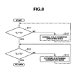
- FIG. 3 is a flow chart showing a process of combustion mode shift for engine start in accordance with a first embodiment.
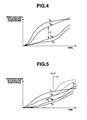
- FIG. 4 is a graph showing changes in temperature of each reference point of a catalytic converter when the catalytic converter is subjected under a high exhaust gas temperature in the first embodiment.
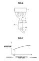
- FIG. 5 is a graph showing changes in temperature of each reference point of the catalytic converter when the catalytic converter is subjected under a low exhaust gas temperature in the first embodiment.
- FIG. 6 is a schematic plan view of an exhaust system of the engine, showing the position of each reference point whose temperature is measured as in the graphs of FIGS. 4 and 5.
- FIG. 7 is a graph showing relationship between fuel injection timing and exhaust gas temperature in the first embodiment.
- FIG. 8 is a flow chart showing a process of combustion mode shift for engine start in accordance with a second embodiment.
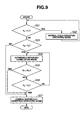
- FIG. 9 is a flow chart showing a process of combustion mode shift for engine start in accordance with a third embodiment.
- FIG. 10 is a flow chart showing a process of combustion mode shift for engine start in accordance with a first variation of the third embodiment in which a process of detecting changes in engine load is modified.
- FIG. 11 is a flow chart showing a process of combustion mode shift for engine start in accordance with a second variation of the third embodiment in which the process of detecting changes in engine load is modified.
- FIG. 12 is a flow chart showing a process of combustion mode shift for engine start in accordance with a fourth embodiment.
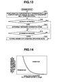
- FIG. 13 is a flow chart showing a process of combustion mode shift for engine start in accordance with a fifth embodiment.
- FIG. 14 is a characteristic diagram showing a permission region and an inhibition region for the extremely retarded combustion mode in the fifth embodiment.
- FIG. 15 is a graph showing changes in an inlet temperature and an internal temperature of a catalytic converter in case the extremely retarded combustion mode is employed, as contrasted with the case where a normal combustion mode is employed.
- FIG. 16 is a graph showing changes in the catalytic converter inlet temperature and catalytic converter internal temperature in case the extremely retarded combustion mode is canceled when the catalytic internal temperature reaches its activation temperature.
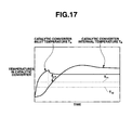
- FIG. 17 is a graph showing changes in the catalytic converter inlet temperature and catalytic converter internal temperature in the fifth embodiment.
- FIG. 18 is a flow chart showing a process of combustion mode shift for engine start in accordance with a sixth embodiment.
- FIG. 19 is a graph showing a permission region and an inhibition region for the extremely retarded combustion mode in the sixth embodiment.
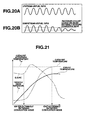
- FIGS. 20A and 20B are graphs showing an air-fuel ratio measured by an upstream air-fuel ratio sensor, and an air-fuel ratio measured by a downstream air-fuel ratio sensor, respectively.
- FIG. 21 is a graph showing changes in an engine temperature, a catalyst temperature, and a quantity of engine-out HC emissions in cold start in accordance with a seventh embodiment.
- FIG. 22 is a graph showing changes in the engine temperature, the catalyst temperature, and the quantity of engine-out HC emissions in cold start in case the catalyst temperature reaches a predetermined temperature T 22 before the engine temperature exceeds a predetermined temperature T 21 .
- FIG. 23 is a graph showing changes in the engine temperature, the catalyst temperature, and the quantity of engine-out HC emissions in cold start in a reference example in which the extremely retarded combustion is continuously employed immediately after engine start.
- FIG. 24 is a graph showing changes in incylinder turbulence in related technology.
- FIG. 1 is a schematic block diagram showing system configuration of an internal combustion engine with a combustion control apparatus in accordance with accompanying embodiments.
- each piston 2 defines a combustion chamber 3, which is connected to an intake air passage 4 via each intake valve not shown, and is connected to an exhaust gas passage 5 via each exhaust valve not shown.
- intake air passage 4 In intake air passage 4 are arranged an air flow meter 6 adapted to measure the amount of intake air, and an electronically controlled throttle valve 7 whose opening is controlled by an actuator 8 in accordance with a control signal from a below-mentioned control unit 25.
- an exhaust purifier 10 such as a catalytic converter having a monolith ceramic catalyst carrier for purifying the exhaust gas.
- air-fuel ratio sensors 11 and 12 In upstream and downstream positions are arranged air-fuel ratio sensors 11 and 12, respectively. Near upstream air-fuel ratio sensor 11 is arranged an exhaust gas temperature sensor 13 adapted to measure the temperature of the exhaust gas at an inlet point of catalytic converter 10.
- a catalyst temperature sensor 31 is disposed in a longitudinally central position of the catalyst carrier of catalytic converter 10, while a catalytic converter outlet temperature sensor 32 is disposed in an outlet position of catalytic converter 10. These sensors 31 and 32 serve for measuring a thermal state of catalytic converter 10.
- a spark plug 14 is disposed in a central apex portion of the roof of combustion chamber 3 to produce a spark within combustion chamber 3.
- a fuel injection valve 15 as a fuel injector is disposed in a portion of the side wall of combustion chamber 3 nearer to intake air passage 4, and adapted to inject or spray fuel directly into combustion chamber 3.
- Fuel is regulated to a predetermined pressure by a high pressure fuel pump 16 and a pressure regulator 17, and then supplied to fuel injection valve 15 via a high pressure fuel passage 18.
- Receiving a control pulse signal fuel injection valve 15 opens to spray the fuel into combustion chamber 3.
- the fuel injection quantity is adjusted in accordance with the period in which fuel injection valve 15 is in an open state.
- a fuel pressure sensor 19 is disposed in high pressure fuel passage 18.
- a low pressure fuel pump 20 feeds fuel to high pressure fuel pump 16.
- Coolant temperature sensor 21 is adapted to measure the temperature of an engine coolant.
- Crank angle sensor 22 is adapted to measure the crank angle.
- Accelerator opening sensor 23 is adapted to measure the depression of an accelerator pedal.
- An electrical control unit 25 is configured to control the quantity and timing of fuel injection, the ignition timing, of internal combustion engine 1.
- the fuel injection timing may be represented by a fuel injection start timing, and the fuel injection quantity may be changed in accordance with the period of fuel injection.
- control unit 25 is configured to receive sensing signals from the above-mentioned sensors. In accordance with engine operating conditions determined in accordance with the input signals, control unit 25 selects one of a homogeneous charge combustion mode and a stratified charge combustion mode, and accordingly controls the opening of electronically controlled throttle valve 7, the quantity and timing of fuel injection of fuel injection valve 15, the ignition timing of spark plug 14, etc.
- control unit 25 selects a normal stratified charge combustion mode to control the fuel injection timing at a proper timing during compression stroke, and to control the ignition timing to be before compression TDC.
- a layer of fuel spray is formed intensively around spark plug 14 and thereby internal combustion engine 1 performs extremely lean stratified charge combustion with an overall air-fuel ratio of about from 30 to 40.
- control unit 25 selects a normal homogeneous charge combustion mode to control the fuel injection timing to be in intake stroke, and to control the ignition timing at or near the MBT point before compression TDC.
- the air-fuel mixture is homogeneous in combustion chamber 3.
- the homogeneous charge combustion mode specifically has a homogeneous stoichiometric combustion mode with a stoichiometric air-fuel ratio, and a homogeneous lean combustion mode with a lean air-fuel ratio of about from 20 to 30.
- Control unit 25 also controls internal combustion engine 1 in a special combustion mode referred to as an extremely retarded combustion mode to retard the combustion so as to raise the exhaust gas temperature quickly when engine 1 is in a cold start state where a request to rapidly raise the temperature of catalytic converter 10 or to rapidly raise the exhaust gas temperature is active.
- a special combustion mode referred to as an extremely retarded combustion mode to retard the combustion so as to raise the exhaust gas temperature quickly when engine 1 is in a cold start state where a request to rapidly raise the temperature of catalytic converter 10 or to rapidly raise the exhaust gas temperature is active.
- the following describes the fuel injection timing and the ignition timing of this extremely retarded combustion mode, with reference to FIGS. 2A through 2C.
- FIGS. 2A, 2B, and 2C are characteristic diagrams showing three examples of the fuel injection timing and the ignition timing of the extremely retarded combustion mode.
- the ignition timing is set within a range of 15°ATDC to 30°ATDC, e.g., at 20°ATDC (phase in crank angle after top dead center) during expansion stroke, while the fuel injection timing or specifically fuel injection start timing is set to be after compression TDC and before the ignition timing.
- the air-fuel ratio is set to be stoichiometric or slightly leaner, such as a value of about 16 to 17.
- the ignition timing specifically to retard the ignition timing to be after compression TDC (ATDC ignition), for promoting catalyst activation and reducing engine out HC emissions.
- the combustion based on ATDC ignition may be stabilized by reducing the period of the combustion.
- the incylinder turbulence serves for promoting flame propagation to enhance the combustion speed.
- high pressure fuel injection in expansion stroke after compression TDC is effective for generating and enhancing the incylinder turbulence in the first example of the extremely retarded combustion. This promotes the flame propagation and enhances the combustion stability in the combustion based on ATDC ignition.
- the first fuel injection prior to the second fuel injection is effective little for enhancing the incylinder turbulence since the incylinder turbulence diminishes during the late stage of compression stroke, but effective for reducing engine out HC emissions and raising the exhaust gas temperature since the injected fuel is dispersed enough within the combustion chamber to promote afterburning of HC emissions due to the ATDC ignition.
- fuel is injected twice in split timings, in which the first fuel injection timing is in compression stroke and the second fuel injection timing is after compression TDC.
- the ignition timing and air-fuel ratio in consideration of two fuel injection steps are the same as in the first example.
- the incylinder turbulence generated by the first fuel injection prior to the second fuel injection diminishes more slowly than in the second example so that the second injection is carried out in the presence of the incylinder turbulence to enhance the incylinder gas flow and turbulence at or near compression TDC.
- the first fuel injection of the third example may be in the first half of compression stroke, it is preferred to set the first fuel injection timing to be in the second half of compression stroke, i.e. at or after 90°BTDC so that the incylinder turbulence is more effectively enhanced near compression TDC.
- the first fuel injection timing is preferably after 45°BTDC, more preferably after 20°BTDC, for enhancing the incylinder gas flow after compression TDC.
- the fuel injection generates and enhances the incylinder turbulence immediately before ignition, and thereby promotes the flame propagation and stabilizes the combustion.
- the late ignition timing of from 15 to 30°ATDC is effective for rapid catalyst activation and afterburning to reduce the engine out HC emissions.
- fuel injection timing retarded to be immediately before the ignition timing is effective for retarding the timing of occurrence and development of the incylinder turbulence, and improving the combustion in flame propagation.
- control unit 25 operates internal combustion engine 1 in a plurality of combustion modes, which are switched in accordance with a thermal state of catalytic converter 10.
- FIG. 3 is a flow chart showing a process of combustion mode shift for engine start to be performed by control unit 25.
- Control unit 25 repeatedly executes the routine of FIG. 3 at intervals of a predetermined processing time interval.
- control unit 25 compares a predetermined first reference temperature T 1 with a catalytic converter outlet temperature T c as defined as the temperature of an inlet point of catalytic converter 10 measured by catalytic converter outlet temperature sensor 32.
- control unit 25 determines whether or not catalytic converter outlet temperature T C is higher than first reference temperature T 1 .
- First reference temperature T 1 is substantially identical to the lowest activation temperature of the associated catalyst, such as a temperature of from 150°C to 200°C.
- control unit 25 operates the engine in a normal cold condition operating mode.
- the engine In the normal cold condition operating mode, the engine is controlled to moderately increase the exhaust gas temperature. The temperature increase is not so rapid as in the extremely retarded combustion mode.
- the fuel injection timing is set to be in intake stroke, and the ignition timing is set to be a little before the MBT point before compression TDC. Fuel injection may be performed during compression stroke in addition to the intake stroke fuel injection.
- control unit 25 operates the engine in the normal cold condition operating mode so that the temperature of catalytic converter 10 gradually increases.
- step S3 control unit 25 compares a predetermined second reference temperature T 2 with a catalyst temperature T B as defined as the temperature of a portion of the catalyst carrier of catalytic converter 10 measured by catalyst temperature sensor 31. Specifically, control unit 25 determines whether or not catalyst temperature T B is higher than second reference temperature T 2 .
- Second reference temperature T 2 is substantially identical to a catalyst full activation temperature for full activity of the catalyst, particularly a little lower than the catalyst full activation temperature, such as a temperature of from 250°C to 300°C.
- control unit 25 operates the engine in the extremely retarded combustion mode.
- catalyst temperature T B is usually lower than second reference temperature T 2 . Accordingly, during cold start, the engine operating mode is shifted from the normal cold condition operating mode to the extremely retarded combustion mode.
- extremely retarded combustion mode the exhaust gas temperature rapidly rises to rapidly warm up catalytic converter 10. The extremely retarded combustion mode continues until catalyst temperature T B exceeds second reference temperature T 2 .
- control unit 25 exits the process for the period when the engine is in a cold state, and enters a normal warmed-up condition operating mode. Specifically, in the normal warmed-up condition operating mode, the engine is operated in the homogeneous charge combustion mode, or in the normal stratified charge combustion mode.
- the extremely retarded combustion mode is inhibited until catalytic converter outlet temperature T C exceeds first reference temperature T 1 . This is effective for avoiding thermal degradation of catalytic converter 10 while reducing the period of catalyst full activation in the extremely retarded combustion mode.
- FIGS. 4 and 5 are graphs showing changes in temperature of each reference point of catalytic converter 10.
- FIG. 4 shows a case where catalytic converter 10 is subjected under a very high exhaust gas temperature.
- FIG. 5 shows a case where catalytic converter 10 is subjected under a relatively low exhaust gas temperature.
- FIG. 6 is a schematic plan view of an exhaust system of the engine, showing the position of each reference point whose temperature is measured as in the graphs of FIGS. 4 and 5.
- the sensors measure a temperature T A at an inlet point A of catalytic converter 10, a temperature T B1 at an upstream point B1 of the catalyst carrier, a temperature T B2 at a downstream point B2 of the catalyst carrier, and temperature T C at an outlet point of catalytic converter 10.
- control unit 25 may be configured to perform the following in the extremely retarded combustion mode: controlling fuel injection valve 15 to inject fuel at a prior fuel injection timing during intake and compression strokes and at a second fuel injection timing; and retarding the second fuel injection timing gradually to a predetermined timing point in an initial stage of the extremely retarded combustion mode.
- control unit 25 may be configured to perform the following in the extremely retarded combustion mode: controlling fuel injection valve 15 to inject fuel at a prior fuel injection timing during intake and compression strokes and at a second fuel injection timing; and retarding the second fuel injection timing gradually to a predetermined timing point in an initial stage of the extremely retarded combustion mode.
- the exhaust gas temperature varies in accordance with the second fuel injection timing as shown in FIG. 7.
- the exhaust gas temperature increases as the second fuel injection timing is retarded.
- the second fuel injection timing may be controlled in such a manner to be advanced near TDC just after shift into the extremely retarded combustion mode, and then to be retarded gradually toward a predetermined timing. This may raise the exhaust gas temperature gradually, which is effective for reducing the thermal distortion of the catalyst carrier more reliably.
- the second fuel injection timing may be temporarily before compression TDC. For example, the period of fuel injection may straddle compression TDC.
- the extremely retarded combustion mode is employed from engine start when catalytic converter 10 is in a completely cold state, it is possible that catalytic converter 10 has a large amount of thermal strain.
- the engine is operated in a plurality of combustion modes, which are switched in accordance with the thermal state of catalytic converter 10. Specifically, the extremely retarded combustion mode is inhibited during catalytic converter 10 being in a predetermined low thermal state. More specifically, the extremely retarded combustion mode is inhibited until catalytic converter outlet temperature T C exceeds first reference temperature T 1 .
- the increase in catalytic converter outlet temperature T C may be considered as indicating that temperatures of catalytic converter 10 rises as a whole. Accordingly, the extremely retarded combustion mode, when employed to raise the exhaust gas temperature after catalytic converter outlet temperature T C exceeds first reference temperature T 1 , does not cause an excessive amount of heat distortion.
- FIG. 8 is a flow chart showing a process of combustion mode shift for engine start in accordance with a second embodiment.
- control unit 25 compares a predetermined third reference temperature T 3 with catalyst temperature T B measured by catalyst temperature sensor 31. Specifically, control unit 25 determines whether or not catalyst temperature T B is higher than third reference temperature T 3 .
- Third reference temperature T 3 is substantially identical to the lowest catalyst activation temperature, such as a temperature of from 150°C to 200°C.
- the routine proceeds to step S12.
- control unit 25 operates the engine in the normal cold condition operating mode.
- step S13 control unit 25 determines whether or not catalyst temperature T B is higher than second reference temperature T 2 .
- step S14 control unit 25 operates the engine in the extremely retarded combustion mode.
- catalyst temperature T B is generally lower than second reference temperature T 2 and the extremely retarded combustion mode is employed at step S14. This raises the exhaust gas temperature and thereby warms up catalytic converter 10. The extremely retarded combustion mode continues until catalyst temperature T B exceeds second reference temperature T 2 .
- control unit 25 terminates the process for the period when the engine is in a cold state and operates the engine in the normal warmed-up condition operating mode, that is, in the homogeneous charge combustion mode, or in the normal stratified charge combustion mode.
- the extremely retarded combustion mode is inhibited until catalyst temperature T B exceeds third reference temperature T 3 .
- This is effective for avoiding thermal degradation of catalytic converter 10 while reducing the period of catalyst full activation in the extremely retarded combustion mode.
- the combustion control apparatus may be constructed without catalytic converter outlet temperature sensor 32.
- the extremely retarded combustion mode is inhibited until catalyst temperature T B exceeds third reference temperature T 3 .
- catalyst temperature T B exceeds third reference temperature T 3
- the catalyst activation is started.
- the internal temperature of the catalyst rises due to the released heat of reaction. Accordingly, even when the exhaust gas temperature rises very high, the spatial thermal gradient in catalytic converter 10 is not so large.
- FIG. 9 is a flow chart showing a process of combustion mode shift for engine start in accordance with a third embodiment.
- control unit 25 compares first reference temperature T 1 with catalytic converter outlet temperature T c measured by catalytic converter outlet temperature sensor 32. Specifically, control unit 25 determines whether or not catalytic converter outlet temperature T C is lower than first reference temperature T 1 .
- the routine proceeds to step S22.
- control unit 25 operates the engine in a normal cold condition operating mode. In the normal cold condition operating mode, the engine is controlled to moderately increase the exhaust gas temperature. The temperature increase is not so rapid as in the extremely retarded combustion mode.
- control unit 25 operates the engine in the normal cold condition operating mode so that the temperature of catalytic converter 10 gradually increases.
- step S21 determines whether or not catalyst temperature T B is lower than second reference temperature T 2 .
- step S23 determines whether or not catalyst temperature T B is lower than second reference temperature T 2 .
- step S24 determines whether or not catalyst temperature T B is lower than second reference temperature T 2 .
- step S24 control unit 25 operates the engine in the extremely retarded combustion mode. In cold start, at the moment catalytic converter outlet temperature T C exceeds first reference temperature T 1 , catalyst temperature T B is usually lower than second reference temperature T 2 .
- control unit 25 determines whether or not catalyst temperature T B is higher than or equal to second reference temperature T 2 .
- the routine proceeds to step S27.
- the routine proceeds back to step S24.
- the extremely retarded combustion mode is active until catalyst temperature T B exceeds second reference temperature T 2 .
- control unit 25 operates the engine in the normal warmed-up condition operating mode. Specifically, in the normal warmed-up condition operating mode, the engine is operated in the homogeneous charge combustion mode, or in the normal stratified charge combustion mode.
- step S25 is executed.
- control unit 25 determines whether or not a throttle opening Th of electronically controlled throttle valve 7 is higher than a predetermined threshold value Th 1 .
- the routine proceeds to step S27.
- the routine proceeds to step S26.
- control unit 25 exits the extremely retarded combustion mode, even when catalyst temperature T B does not exceed second reference temperature T 2 , if throttle opening Th exceeds threshold value Th 1 .
- the extremely retarded combustion mode is shifted to the normal warmed-up condition operating mode.
- the normal cold condition operating mode may be employed until catalyst temperature T B exceeds second reference temperature T 2 .
- the extremely retarded combustion mode is inhibited until catalytic converter outlet temperature T C exceeds first reference temperature T 1 . This is effective for avoiding thermal degradation of catalytic converter 10 while reducing the period of catalyst full activation in the extremely retarded combustion mode.
- FIGS. 10 and 11 are flow charts showing modifications to the routine of FIG. 9.
- Step S25 in the routine of FIG. 9 is replaced with step S25A and S25B to provide the routine of FIGS. 10 and 11, respectively, in which whether the engine load is above a predetermined level is determined in accordance with engine operating conditions such as the operating state of auxiliary equipment and the operating state of an idle switch.
- control unit 25 determines whether or not an auxiliary load is ON.
- the auxiliary load is a load of auxiliary equipment such as a compressor for air-conditioner.
- the routine proceeds to step S27.
- step S25A is NO, the routine proceeds to step S26.
- control unit 25 exits the extremely retarded combustion mode, even when catalyst temperature T B does not exceed second reference temperature T 2 , if the auxiliary load is ON.
- control unit 25 may exit the extremely retarded combustion mode when the sum of loads of auxiliary devices exceeds a predetermined level.
- control unit 25 determines whether or not an idle switch is ON.
- the routine proceeds to step S27.
- the routine proceeds to step S26.
- control unit 25 exits the extremely retarded combustion mode, even when catalyst temperature T B does not exceed second reference temperature T 2 , if the idle switch is ON.
- the ON signal of the idle switch indicates that the depression of the accelerator pedal or throttle opening Th of electronically controlled throttle valve 7 is zero.
- the idle switch signal may be produced in a non-physical process.
- the idle switch signal may be generated by processing the sensing data from accelerator opening sensor 23.
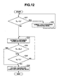
- FIG. 12 is a flow chart showing a process of combustion mode shift for engine start in accordance with a fourth embodiment.
- control unit 25 compares a predetermined third reference temperature T 3 with catalyst temperature T B measured by catalyst temperature sensor 31. Specifically, control unit 25 determines whether or not catalyst temperature T B is lower than third reference temperature T 3 .
- Third reference temperature T 3 is substantially identical to the lowest catalyst activation temperature, such as a temperature from 150°C to 200°C.
- the routine proceeds to step S32.
- control unit 25 operates the engine in the normal cold condition operating mode.
- step S33 control unit 25 operates the engine in the extremely retarded combustion mode.
- step S35 control unit 25 determines whether or not catalyst temperature T B is higher than or equal to second reference temperature T 2 .
- step S36 the routine proceeds back to step S33.
- the extremely retarded combustion mode is active until catalyst temperature T B exceeds second reference temperature T 2 .
- control unit 25 operates the engine in the normal warmed-up condition operating mode, that is, in the homogeneous charge combustion mode, or in the normal stratified charge combustion mode.
- step S34 is executed.
- control unit 25 determines whether or not throttle opening Th of electronically controlled throttle valve 7 is higher than threshold value Th 1 .
- the routine proceeds to step S36.
- the routine proceeds to step S35.
- control unit 25 exits the extremely retarded combustion mode, even when catalyst temperature T B does not exceed second reference temperature T 2 , if throttle opening Th exceeds threshold value Th 1 .
- the extremely retarded combustion mode is inhibited until catalyst temperature T B exceeds third reference temperature T 3 .
- This is effective for avoiding thermal degradation of catalytic converter 10 while reducing the period of catalyst full activation in the extremely retarded combustion mode.
- the combustion control apparatus may be constructed without catalytic converter outlet temperature sensor 32.
- Step S34 in the routine of FIG. 12 may be replaced with step S25A concerning the auxiliary load, or step S25B concerning the idle switch signal, as the modifications of FIGS. 10 and 11.
- FIG. 13 is a flow chart showing a process of combustion mode shift for engine start in accordance with a fifth embodiment.
- control unit 25 reads a catalytic converter inlet temperature T A defined as the temperature of an inlet point of catalytic converter 10 which is measured by exhaust gas temperature sensor 13, and determines or computes the rate of change dT A of catalytic converter inlet temperature T A , specifically the amount of change per unit time in catalytic converter inlet temperature T A .
- control unit 25 determines whether or not the catalyst is activated based on engine conditions such as a coolant temperature at engine start and catalytic converter inlet temperature T A at engine start.
- control unit 25 operates the engine in the normal warmed-up condition operating mode, specifically in the homogeneous charge combustion mode, or in the normal stratified charge combustion mode.
- control unit 25 operates the engine in the extremely retarded combustion mode. Thereby, the exhaust gas temperature rises rapidly.
- control unit 25 determines or judges based on catalytic converter inlet temperature T A and its rate of change dT A whether or not the thermal state of catalytic converter 10 has reached a predetermined stage before full activation. Specifically, control unit 25 judges whether the point indicative of catalytic converter inlet temperature T A and its rate of change dT A is in an inhibition region or a permission region of the graph as shown in FIG. 14. While the engine is in the permission region, control unit 25 continues the extremely retarded combustion mode until the engine enters the inhibition region. When control unit 25 judges that the engine enters the inhibition region, the routine proceeds to step S45, where the extremely retarded combustion mode is canceled and shifted into the normal warmed-up condition operating mode.
- the above-mentioned region of inhibition conditions is defined in such a manner that the catalyst temperature does not rise to excessively overshoot the full activation temperature after cancellation of the extremely retarded combustion mode.
- the lowest value of catalytic converter inlet temperature T A at which the extremely retarded combustion mode is cancelled or inhibited decreases with increasing rate of change of catalytic converter inlet temperature dT A . This prevents excessive overshoot of the catalyst temperature and heat strain due to extremely large spatial thermal gradients.
- FIG. 15 is a graph showing changes in catalytic converter inlet temperature T A (substantially identical to the exhaust gas temperature) and catalytic converter internal temperature T B in case the extremely retarded combustion mode continues after cold start, as contrasted with the case as indicated by broken lines where the normal combustion mode continues after cold start.
- the exhaust gas temperature catalytic converter inlet temperature
- the exhaust gas temperature rises rapidly after cold start so that the internal temperature reaches a catalyst activation temperature (full activation temperature) T 11 within a very short period of time.
- the difference between the inlet temperature and internal temperature, namely the spatial thermal gradient in the catalyst carrier is lager at catalyst activation temperature T 11 in the case of the extremely retarded combustion mode as indicated by solid lines than in the case of mild heating as indicated by broken lines.
- the rapid heating due to the extremely retarded combustion mode tends to cause a large amount of heat strain in catalytic converter 10.
- FIG. 16 is a graph showing changes in the catalytic converter inlet temperature and catalytic converter internal temperature when catalytic internal temperature T B reaches catalyst activation temperature T 11 and the extremely retarded combustion mode is canceled.
- the heat in components in upstream of the exhaust system and the reaction heat of the catalyst itself continue to raise the internal temperature of catalytic converter 10.
- the internal temperature of catalytic converter 10 overshoots a temperature of degrading the catalyst.
- FIG. 17 is a graph showing changes in the catalytic converter inlet temperature and the catalytic converter internal temperature in the case of the fifth embodiment where the extremely retarded combustion mode is canceled before internal temperature T B reaches catalyst activation temperature T 11 .
- the extremely retarded combustion mode is cancelled when the internal temperature is a temperature T 12 which is lower than catalyst activation temperature T 11 , so that the internal temperature rises even after the cancellation of the extremely retarded combustion mode but does not reach the temperature of degrading the catalyst.
- catalytic converter inlet temperature T A decreases immediately, and the difference ⁇ T between internal temperature T B and catalytic converter inlet temperature T A when internal temperature T B reaches catalyst activation temperature T 11 is smaller than in the cases of FIGS. 15 and 16.
- catalytic converter inlet temperature T A of catalytic converter 10 is measured directly by exhaust gas temperature sensor 13 in the above-mentioned embodiment, catalytic converter inlet temperature T A may be estimated in accordance with the intake air quantity since catalytic converter inlet temperature T A is correlated with the intake air quantity of the internal combustion engine.
- FIGS. 18 and 19 show a sixth embodiment.
- the thermal state of catalytic converter 10 is determined by means of both exhaust gas temperature sensor 13 and catalyst temperature sensor 31. That is, catalytic converter inlet temperature T A and internal temperature T B of catalytic converter 10 are both measured.
- FIG. 18 is a flow chart showing a process of combustion mode shift for engine start in accordance with the sixth embodiment.
- control unit 25 reads catalytic converter inlet temperature T A of catalytic converter 10 measured by exhaust gas temperature sensor 13 and internal temperature T B of catalytic converter 10 measured by catalyst temperature sensor 31.
- control unit 25 determines whether or not the catalyst is activated based on engine conditions such as the coolant temperature at engine start and internal temperature T B at engine start. For example, during engine restart in warmed-up conditions, the catalyst is already activated.
- the routine proceeds to step S45.
- control unit 25 operates the engine in the normal warmed-up condition operating mode, namely in the homogeneous charge combustion mode, or in the normal stratified charge combustion mode.
- control unit 25 operates the engine in the extremely retarded combustion mode. Thereby, the exhaust gas temperature rises rapidly.
- control unit 25 determines or judges based on catalytic converter inlet temperature T A and catalytic converter internal temperature T B whether or not the thermal state of catalytic converter 10 has reached a predetermined stage before full activation. Specifically, control unit 25 judges whether the point of catalytic converter inlet temperature T A and catalytic converter internal temperature T B is in an inhibition region or a permission region of the graph as shown in FIG. 19. While the engine in the permission region, control unit 25 continues the extremely retarded combustion mode until the engine enters the inhibition region. When control unit 25 judges that the engine enters the inhibition region, the routine proceeds to step S45, where the extremely retarded combustion mode is canceled and shifted into the normal combustion mode.
- the above-mentioned region of inhibition conditions is defined in such a manner that the catalyst temperature does not rise to excessively overshoot the full activation temperature after cancellation of the extremely retarded combustion mode.
- the lowest value of catalytic converter internal temperature T B at which the extremely retarded combustion mode is cancelled or inhibited decreases with increasing catalytic converter inlet temperature T A . This prevents excessive overshoot of the catalyst temperature and heat strain due to extremely large spatial thermal gradients.
- the catalytic converter inlet temperature T A of catalytic converter 10 is measured directly by exhaust gas temperature sensor 13 in the above-mentioned embodiment, the catalytic converter inlet temperature T A may be estimated in accordance with the intake air quantity since catalytic converter inlet temperature T A is correlated with the intake air quantity of the internal combustion engine.
- the internal temperature T B of catalytic converter 10 is measured directly by catalyst temperature sensor 31 in the above-mentioned embodiment, the internal temperature T B may be estimated in accordance with other parameters such as the oxygen storage ability of catalytic converter 10 which is correlated with the catalyst temperature.
- the exhaust air-fuel ratio of the internal combustion engine is controlled to fluctuate in a suitable period and amplitude as shown in FIG. 20A.
- This control is implemented by general technology of air-fuel ratio feedback control.
- the air-fuel ratio measured by upstream air-fuel ratio sensor 11 changes in accordance with the exhaust air-fuel ratio of the engine.
- the air-fuel ratio measured by downstream air-fuel ratio sensor 12 changes as shown in FIG.
- control unit 25 judges that the catalyst temperature reaches the lowest activation temperature before full activation.
- FIG. 23 is a graph showing changes in the engine temperature (coolant temperature or lubricating oil temperature), the catalyst temperature, and the generated quantity of HC (called engine-out HC emissions) in cold start in a reference example in which the extremely retarded combustion is continuously employed immediately after engine start.
- the engine temperature gradually increases with time after engine start.
- the catalyst temperature of catalytic converter 10 also immediately and gradually increases effectively heated by the extremely retarded combustion.
- the quantity of engine-out HC emissions is large due to increase of the fuel wall flows just after cold start, and decreases with increase in the engine temperature.
- control unit 25 inhibits the extremely retarded combustion mode while the engine is in a predetermined low thermal state. Specifically, control unit 25 inhibits the extremely retarded combustion mode after cold start while the engine temperature is in a predetermined cold state, i.e. until the engine temperature exceeds a predetermined first threshold temperature T 21 , as shown in FIG. 21.
- the normal cold condition operating mode serves to increase the exhaust gas temperature without increasing the wall flows of the fuel spray.
- the normal cold condition operating mode also serves to gradually warm up catalytic converter 10 by the heat of the exhaust gas.
- the wall flows of the fuel spray is in a lower level, and thereby the quantity of engine-out HC emissions is smaller than in the case of FIG. 23.
- control unit 25 initiates or enters the extremely retarded combustion mode.
- the exhaust gas temperature rapidly increases to heat catalytic converter 10.
- catalytic converter 10 is activated, the temperature of catalytic converter 10 further rapidly rises.
- the quantity of engine-out HC emissions temporarily and slightly increases just after the entrance into the extremely retarded combustion mode, and rapidly decreases with increase in the engine temperature.
- Second threshold temperature T 22 is substantially identical to a catalyst activation temperature of catalytic converter 10. As shown in FIG. 22, if the temperature of catalytic converter 10 reaches or exceeds second threshold temperature T 22 before the engine temperature exceeds first threshold temperature T 21 , the initiating the extremely retarded combustion mode is inhibited, that is, the normal cold condition operating mode is not switched to the extremely retarded combustion mode but directly to the normal warmed-up condition operating mode. This avoids adverse effects in fuel consumption due to the extremely retarded combustion mode.
- the combustion control apparatus in accordance with the above-mentioned seventh embodiment wherein the extremely retarded combustion mode is employed after the engine temperature exceeds first threshold temperature T 21 , is effective for preventing the quantity of engine-out HC emissions from transiently and excessively increasing due to the increase in the wall flows of the fuel spray in cold start.
- the extremely retarded combustion mode serves to rapidly raise the exhaust gas temperature and thereby to rapidly raise the temperature of catalytic converter 10, so that the period required for catalyst activation is comparable to that in the case where the extremely retarded combustion mode is used just after cold start as shown in FIG. 23.
- the exhaust gas temperature is very high in the extremely retarded combustion mode. Accordingly, in case the extremely retarded combustion mode is employed just after cold start in which catalytic converter 10 is in a completely cold state, it is possible that catalytic converter 10 is rapidly heated, and that thermal strain is generated in catalytic converter 10.
- the combustion control apparatus in accordance with this embodiment wherein the extremely retarded combustion mode is entered after catalytic converter 10 is heated above a predetermined level, is effective for reducing the period required for full activation of the catalyst and for avoiding large thermal strain or thermal degradation of catalytic converter 10.
- the extremely retarded combustion mode of the above-mentioned embodiments may be employed in an engine system including a NOx trap catalyst as catalytic converter 10 to recover sulfur poisoning thereof.
- a NOx trap catalyst serves to adsorb NOx when the air-fuel ratio of the exhaust gas flowing into the catalyst is lean, and to perform a purifying process by releasing the adsorbed NOx when the exhaust air-fuel ratio is rich.
- SOx sulfur content
- the NOx trap catalyst is degraded in the performance of NOx adsorption.
- the extremely retarded combustion of the shown embodiments may be employed to obtain the exhaust gas of high temperatures.
Landscapes
- Engineering & Computer Science (AREA)
- Chemical & Material Sciences (AREA)
- Combustion & Propulsion (AREA)
- Mechanical Engineering (AREA)
- General Engineering & Computer Science (AREA)
- Electrical Control Of Air Or Fuel Supplied To Internal-Combustion Engine (AREA)
- Exhaust Gas After Treatment (AREA)
- Combined Controls Of Internal Combustion Engines (AREA)
Applications Claiming Priority (4)
| Application Number | Priority Date | Filing Date | Title |
|---|---|---|---|
| JP2005158509A JP4577091B2 (ja) | 2005-05-31 | 2005-05-31 | 筒内直接噴射式火花点火内燃機関の制御装置 |
| JP2005158507A JP2006336473A (ja) | 2005-05-31 | 2005-05-31 | 筒内直接噴射式火花点火内燃機関の制御装置 |
| JP2005158510A JP4544036B2 (ja) | 2005-05-31 | 2005-05-31 | 筒内直接噴射式火花点火内燃機関の制御装置 |
| JP2005185909A JP4581867B2 (ja) | 2005-06-27 | 2005-06-27 | 筒内直接噴射式火花点火内燃機関の制御装置 |
Publications (1)
| Publication Number | Publication Date |
|---|---|
| EP1728996A1 true EP1728996A1 (fr) | 2006-12-06 |
Family
ID=37025019
Family Applications (1)
| Application Number | Title | Priority Date | Filing Date |
|---|---|---|---|
| EP06011018A Withdrawn EP1728996A1 (fr) | 2005-05-31 | 2006-05-29 | Procédé et dispositif de commande de combustion pour un moteur à injection directe et allumage commandé |
Country Status (2)
| Country | Link |
|---|---|
| US (1) | US7958720B2 (fr) |
| EP (1) | EP1728996A1 (fr) |
Cited By (3)
| Publication number | Priority date | Publication date | Assignee | Title |
|---|---|---|---|---|
| EP2806127A4 (fr) * | 2012-01-18 | 2017-05-17 | Toyota Jidosha Kabushiki Kaisha | Dispositif de régulation pour moteur à combustion interne |
| EP3115586A4 (fr) * | 2014-03-05 | 2018-04-11 | Yanmar Co., Ltd. | Dispositif de commande d'injection de carburant pour moteur à combustion interne |
| WO2021091752A1 (fr) * | 2019-11-07 | 2021-05-14 | Saudi Arabian Oil Company | Moteurs à allumage par compression et leurs procédés de fonctionnement dans des conditions de ralenti rapide à démarrage à froid |
Families Citing this family (17)
| Publication number | Priority date | Publication date | Assignee | Title |
|---|---|---|---|---|
| US7505845B2 (en) * | 2006-12-25 | 2009-03-17 | Nissan Motor Co., Ltd. | Control of internal combustion engine |
| DE102007056217A1 (de) * | 2007-11-22 | 2009-05-28 | Robert Bosch Gmbh | Verfahren und Steuergerät zum Aufheizen eines Katalysators im Abgassystem eines aufgeladenen Verbrennungsmotors |
| JP4992704B2 (ja) * | 2007-12-25 | 2012-08-08 | 日産自動車株式会社 | 筒内直接燃料噴射式火花点火エンジンの排気制御装置 |
| US8370017B2 (en) | 2009-07-13 | 2013-02-05 | Ford Global Technologies, Llc | Smart vehicle sensor |
| JP4858582B2 (ja) * | 2009-07-16 | 2012-01-18 | マツダ株式会社 | 火花点火式エンジンの制御方法および火花点火式エンジン |
| JP5310644B2 (ja) * | 2010-04-28 | 2013-10-09 | 株式会社デンソー | 触媒温度状態診断装置 |
| US8267067B2 (en) * | 2011-03-08 | 2012-09-18 | Ford Global Technologies, Llc | Method for starting an engine automatically |
| US9133782B1 (en) * | 2011-03-24 | 2015-09-15 | Plant Oil Powered Diesel Fuel Systems, Inc. | System and method of multi-fuel engine control |
| JP5839006B2 (ja) * | 2013-08-27 | 2016-01-06 | トヨタ自動車株式会社 | 内燃機関の自動停止制御装置 |
| DE102014000467A1 (de) * | 2014-01-16 | 2015-07-16 | Andreas Stihl Ag & Co. Kg | "Arbeitsgerät und Verfahren zur Ermittlung der Startbedingungen eines Arbeitsgerätes" |
| CN105865140B (zh) * | 2016-04-20 | 2020-04-17 | 合肥华凌股份有限公司 | 制冷设备 |
| GB2560303B (en) * | 2017-02-24 | 2019-10-16 | Jaguar Land Rover Ltd | Exhaust gas treatment system and method |
| DE102017208857A1 (de) * | 2017-05-24 | 2018-12-13 | Volkswagen Aktiengesellschaft | Verfahren zum Betreiben einer Brennkraftmaschine, Brennkraftmaschine und Kraftfahrzeug |
| EP3784893B1 (fr) * | 2018-04-25 | 2023-11-08 | Volvo Truck Corporation | Agencement de moteur à combustion interne et procédé de commande du fonctionnement de celui-ci |
| GB2575091B (en) * | 2018-06-29 | 2021-09-29 | Jaguar Land Rover Ltd | Controller for a fuel injection system |
| WO2020002440A1 (fr) * | 2018-06-29 | 2020-01-02 | Jaguar Land Rover Limited | Dispositif de commande pour système d'injection de carburant |
| GB2575092B (en) * | 2018-06-29 | 2021-09-22 | Jaguar Land Rover Ltd | Controller for a fuel injection system |
Citations (10)
| Publication number | Priority date | Publication date | Assignee | Title |
|---|---|---|---|---|
| US6112716A (en) * | 1998-04-13 | 2000-09-05 | Mitsubishi Denki Kabushiki Kaisha | Fuel injection control system for internal combustion engine of cylinder injection type |
| EP1158150A2 (fr) * | 2000-05-24 | 2001-11-28 | Mitsubishi Jidosha Kogyo Kabushiki Kaisha | Moteur à combustion à injection directe et méthode de contrôle du moteur |
| JP3325230B2 (ja) | 1998-08-03 | 2002-09-17 | マツダ株式会社 | 筒内噴射式エンジンの触媒暖機方法及び同装置 |
| US20040163379A1 (en) * | 2001-03-15 | 2004-08-26 | Ekkehard Pott | Method for warming up a catalytic converter arranged downstream from a spark-ignition, direct injection internal combustion engine |
| DE10305941A1 (de) * | 2003-02-12 | 2004-08-26 | Daimlerchrysler Ag | Verfahren zum Betrieb einer Brennkraftmaschine mit Kraftstoffdirekteinspritzung |
| JP2005158510A (ja) | 2003-11-26 | 2005-06-16 | Nissan Motor Co Ltd | 燃料電池車両用の熱交換器 |
| JP2005158509A (ja) | 2003-11-26 | 2005-06-16 | Nissan Motor Co Ltd | 燃料電池システム |
| JP2005158507A (ja) | 2003-11-26 | 2005-06-16 | Jst Mfg Co Ltd | プレスフィット用コンタクト及びこれを用いたプレスフィットコネクタ |
| JP2005185909A (ja) | 2003-12-25 | 2005-07-14 | Snt Co | コーティング方法及び装置 |
| EP1643107A1 (fr) * | 2004-09-30 | 2006-04-05 | Nissan Motor Co., Ltd. | Procédé et dispositif de commande de combustion pour un moteur à injection directe et allumage commandé |
Family Cites Families (23)
| Publication number | Priority date | Publication date | Assignee | Title |
|---|---|---|---|---|
| JPH03246335A (ja) | 1990-02-23 | 1991-11-01 | Nissan Motor Co Ltd | 車両用駆動力制御装置 |
| JPH06159109A (ja) | 1992-11-27 | 1994-06-07 | Nippondenso Co Ltd | 車両用駆動力制御装置 |
| JP3157061B2 (ja) * | 1993-04-26 | 2001-04-16 | 株式会社日立製作所 | 触媒劣化診断システム |
| JPH08303337A (ja) | 1995-05-09 | 1996-11-19 | Mitsubishi Motors Corp | エンジンの点火時期制御装置 |
| JP3309669B2 (ja) | 1995-10-02 | 2002-07-29 | 日産自動車株式会社 | 内燃機関の二次空気供給装置 |
| JPH09310636A (ja) | 1996-05-20 | 1997-12-02 | Unisia Jecs Corp | 内燃機関の空燃比制御装置 |
| JP3257420B2 (ja) | 1996-11-21 | 2002-02-18 | 三菱自動車工業株式会社 | 筒内噴射型内燃機関 |
| JP3796919B2 (ja) | 1997-03-19 | 2006-07-12 | トヨタ自動車株式会社 | 筒内直接噴射式内燃機関の燃料噴射制御装置 |
| JP3812154B2 (ja) | 1997-08-06 | 2006-08-23 | マツダ株式会社 | エンジンの制御装置 |
| JP3409696B2 (ja) | 1998-06-01 | 2003-05-26 | 日産自動車株式会社 | 内燃機関の排気浄化装置 |
| JP3613023B2 (ja) | 1998-08-26 | 2005-01-26 | マツダ株式会社 | 筒内噴射式エンジンの制御装置 |
| DE10007242C2 (de) * | 2000-02-17 | 2003-03-20 | Daimler Chrysler Ag | Verfahren und Vorrichtung zum Schutz des Katalysators einer Brennkraftmaschine gegen Überhitzung |
| DE10020104A1 (de) * | 2000-04-22 | 2001-10-31 | Bosch Gmbh Robert | Verfahren zum Starten einer mehrzylindrigen Brennkraftmaschine |
| JP4038989B2 (ja) | 2001-02-09 | 2008-01-30 | 三菱自動車工業株式会社 | 筒内噴射型内燃機関 |
| JP4560978B2 (ja) | 2001-03-30 | 2010-10-13 | マツダ株式会社 | ターボ過給機付火花点火式直噴エンジン |
| DE60211990T2 (de) * | 2001-03-30 | 2007-01-25 | Mazda Motor Corp. | Direkteinspritz- und Funkengezündeter Motor mit einer Turboaufladevorrichtung, Steuermethode und rechnerlesbares Speichermedium dafür |
| US7198952B2 (en) * | 2001-07-18 | 2007-04-03 | Toyota Jidosha Kabushiki Kaisha | Catalyst deterioration detecting apparatus and method |
| JP4062990B2 (ja) | 2002-07-02 | 2008-03-19 | トヨタ自動車株式会社 | 筒内噴射式火花点火内燃機関 |
| JP4093919B2 (ja) | 2003-06-03 | 2008-06-04 | 株式会社日立製作所 | ヒータ付き排気ガスセンサを備えた内燃機関の制御装置 |
| JP4345397B2 (ja) | 2003-07-30 | 2009-10-14 | 日産自動車株式会社 | エンジンの排気浄化装置 |
| JP4428974B2 (ja) | 2003-09-11 | 2010-03-10 | トヨタ自動車株式会社 | 内燃機関の排気浄化装置 |
| JP2005113885A (ja) | 2003-10-10 | 2005-04-28 | Nissan Motor Co Ltd | 内燃機関 |
| US7096853B2 (en) * | 2004-01-28 | 2006-08-29 | Nissan Motor Co., Ltd. | Direct fuel injection/spark ignition engine control device |
-
2006
- 2006-05-29 EP EP06011018A patent/EP1728996A1/fr not_active Withdrawn
- 2006-05-31 US US11/443,179 patent/US7958720B2/en not_active Expired - Fee Related
Patent Citations (10)
| Publication number | Priority date | Publication date | Assignee | Title |
|---|---|---|---|---|
| US6112716A (en) * | 1998-04-13 | 2000-09-05 | Mitsubishi Denki Kabushiki Kaisha | Fuel injection control system for internal combustion engine of cylinder injection type |
| JP3325230B2 (ja) | 1998-08-03 | 2002-09-17 | マツダ株式会社 | 筒内噴射式エンジンの触媒暖機方法及び同装置 |
| EP1158150A2 (fr) * | 2000-05-24 | 2001-11-28 | Mitsubishi Jidosha Kogyo Kabushiki Kaisha | Moteur à combustion à injection directe et méthode de contrôle du moteur |
| US20040163379A1 (en) * | 2001-03-15 | 2004-08-26 | Ekkehard Pott | Method for warming up a catalytic converter arranged downstream from a spark-ignition, direct injection internal combustion engine |
| DE10305941A1 (de) * | 2003-02-12 | 2004-08-26 | Daimlerchrysler Ag | Verfahren zum Betrieb einer Brennkraftmaschine mit Kraftstoffdirekteinspritzung |
| JP2005158510A (ja) | 2003-11-26 | 2005-06-16 | Nissan Motor Co Ltd | 燃料電池車両用の熱交換器 |
| JP2005158509A (ja) | 2003-11-26 | 2005-06-16 | Nissan Motor Co Ltd | 燃料電池システム |
| JP2005158507A (ja) | 2003-11-26 | 2005-06-16 | Jst Mfg Co Ltd | プレスフィット用コンタクト及びこれを用いたプレスフィットコネクタ |
| JP2005185909A (ja) | 2003-12-25 | 2005-07-14 | Snt Co | コーティング方法及び装置 |
| EP1643107A1 (fr) * | 2004-09-30 | 2006-04-05 | Nissan Motor Co., Ltd. | Procédé et dispositif de commande de combustion pour un moteur à injection directe et allumage commandé |
Cited By (5)
| Publication number | Priority date | Publication date | Assignee | Title |
|---|---|---|---|---|
| EP2806127A4 (fr) * | 2012-01-18 | 2017-05-17 | Toyota Jidosha Kabushiki Kaisha | Dispositif de régulation pour moteur à combustion interne |
| EP3115586A4 (fr) * | 2014-03-05 | 2018-04-11 | Yanmar Co., Ltd. | Dispositif de commande d'injection de carburant pour moteur à combustion interne |
| US10612487B2 (en) | 2014-03-05 | 2020-04-07 | Yanmar Co., Ltd. | Fuel injection control device for internal combustion engine |
| WO2021091752A1 (fr) * | 2019-11-07 | 2021-05-14 | Saudi Arabian Oil Company | Moteurs à allumage par compression et leurs procédés de fonctionnement dans des conditions de ralenti rapide à démarrage à froid |
| US11391230B2 (en) | 2019-11-07 | 2022-07-19 | Saudi Arabian Oil Company | Compression ignition engines and methods for operating the same under cold start fast idle conditions |
Also Published As
| Publication number | Publication date |
|---|---|
| US7958720B2 (en) | 2011-06-14 |
| US20060266020A1 (en) | 2006-11-30 |
Similar Documents
| Publication | Publication Date | Title |
|---|---|---|
| US7958720B2 (en) | Combustion control apparatus for direct-injection spark-ignition internal combustion engine | |
| US7159566B2 (en) | Control method and apparatus for direct injection spark ignited internal combustion engine | |
| JP4250856B2 (ja) | 筒内噴射型内燃機関 | |
| US10309327B2 (en) | Control device for internal combustion engine | |
| EP1647690B1 (fr) | Procédé et dispositif de commande de combustion pour un moteur à injection directe et allumage commandé | |
| US6438943B1 (en) | In-cylinder injection type internal combustion engine | |
| US7690369B2 (en) | Fuel pressure controlling device of engine | |
| JP2006258027A (ja) | 内燃機関の制御装置 | |
| JP4840240B2 (ja) | 内燃機関の制御システム | |
| JP4631725B2 (ja) | 筒内直接噴射式火花点火内燃機関の制御装置 | |
| JP4581887B2 (ja) | 内燃機関の制御装置 | |
| JP3582415B2 (ja) | 直噴火花点火式内燃機関の制御装置 | |
| JP4702214B2 (ja) | 筒内噴射式内燃機関の始動制御装置 | |
| JP5831160B2 (ja) | 内燃機関の制御装置 | |
| JP3613020B2 (ja) | 筒内噴射式エンジンの制御装置 | |
| JP4333548B2 (ja) | 筒内直接噴射式火花点火内燃機関の制御装置 | |
| JP4581867B2 (ja) | 筒内直接噴射式火花点火内燃機関の制御装置 | |
| JP4385916B2 (ja) | 筒内直接噴射式火花点火内燃機関の制御装置 | |
| JP2010163930A (ja) | 直噴火花点火式内燃機関の制御装置 | |
| JP4631724B2 (ja) | 筒内直接噴射式火花点火内燃機関の制御装置 | |
| JP2008075533A (ja) | 筒内直接噴射式火花点火内燃機関の制御装置及び制御方法 | |
| JP4544036B2 (ja) | 筒内直接噴射式火花点火内燃機関の制御装置 | |
| JP4577091B2 (ja) | 筒内直接噴射式火花点火内燃機関の制御装置 | |
| JP4525468B2 (ja) | 筒内直接噴射式火花点火内燃機関の制御装置 | |
| JP2023030452A (ja) | 内燃エンジンの制御装置 |
Legal Events
| Date | Code | Title | Description |
|---|---|---|---|
| PUAI | Public reference made under article 153(3) epc to a published international application that has entered the european phase |
Free format text: ORIGINAL CODE: 0009012 |
|
| 17P | Request for examination filed |
Effective date: 20060529 |
|
| AK | Designated contracting states |
Kind code of ref document: A1 Designated state(s): AT BE BG CH CY CZ DE DK EE ES FI FR GB GR HU IE IS IT LI LT LU LV MC NL PL PT RO SE SI SK TR |
|
| AX | Request for extension of the european patent |
Extension state: AL BA HR MK YU |
|
| AKX | Designation fees paid |
Designated state(s): DE FR GB |
|
| 17Q | First examination report despatched |
Effective date: 20080201 |
|
| STAA | Information on the status of an ep patent application or granted ep patent |
Free format text: STATUS: THE APPLICATION IS DEEMED TO BE WITHDRAWN |
|
| 18D | Application deemed to be withdrawn |
Effective date: 20161201 |