EP1727979B1 - Vorrichtung und verfahren zur steuerung einer dickstoffpumpe - Google Patents
Vorrichtung und verfahren zur steuerung einer dickstoffpumpe Download PDFInfo
- Publication number
- EP1727979B1 EP1727979B1 EP05716190A EP05716190A EP1727979B1 EP 1727979 B1 EP1727979 B1 EP 1727979B1 EP 05716190 A EP05716190 A EP 05716190A EP 05716190 A EP05716190 A EP 05716190A EP 1727979 B1 EP1727979 B1 EP 1727979B1
- Authority
- EP
- European Patent Office
- Prior art keywords
- piston
- cylinder
- time
- pump
- reversing
- Prior art date
- Legal status (The legal status is an assumption and is not a legal conclusion. Google has not performed a legal analysis and makes no representation as to the accuracy of the status listed.)
- Expired - Lifetime
Links
- 238000000034 method Methods 0.000 title claims abstract description 18
- 230000002441 reversible effect Effects 0.000 claims abstract description 23
- 238000005259 measurement Methods 0.000 claims abstract description 18
- 230000002123 temporal effect Effects 0.000 claims abstract description 6
- 238000006073 displacement reaction Methods 0.000 claims abstract 3
- 238000011156 evaluation Methods 0.000 claims description 14
- 239000000463 material Substances 0.000 claims description 7
- 230000000977 initiatory effect Effects 0.000 claims 11
- 230000003116 impacting effect Effects 0.000 claims 2
- 238000000926 separation method Methods 0.000 claims 2
- 230000035484 reaction time Effects 0.000 claims 1
- 238000004364 calculation method Methods 0.000 abstract description 7
- 230000001960 triggered effect Effects 0.000 abstract description 7
- 238000001514 detection method Methods 0.000 description 5
- 239000002002 slurry Substances 0.000 description 4
- 230000004044 response Effects 0.000 description 3
- 239000010802 sludge Substances 0.000 description 3
- 230000001419 dependent effect Effects 0.000 description 2
- 238000010586 diagram Methods 0.000 description 2
- 230000007246 mechanism Effects 0.000 description 2
- 230000001133 acceleration Effects 0.000 description 1
- 230000008901 benefit Effects 0.000 description 1
- 230000008859 change Effects 0.000 description 1
- 238000012986 modification Methods 0.000 description 1
- 230000004048 modification Effects 0.000 description 1
- 238000005086 pumping Methods 0.000 description 1
- 230000011664 signaling Effects 0.000 description 1
Images

Classifications
-
- F—MECHANICAL ENGINEERING; LIGHTING; HEATING; WEAPONS; BLASTING
- F04—POSITIVE - DISPLACEMENT MACHINES FOR LIQUIDS; PUMPS FOR LIQUIDS OR ELASTIC FLUIDS
- F04B—POSITIVE-DISPLACEMENT MACHINES FOR LIQUIDS; PUMPS
- F04B7/00—Piston machines or pumps characterised by having positively-driven valving
- F04B7/02—Piston machines or pumps characterised by having positively-driven valving the valving being fluid-actuated
-
- F—MECHANICAL ENGINEERING; LIGHTING; HEATING; WEAPONS; BLASTING
- F04—POSITIVE - DISPLACEMENT MACHINES FOR LIQUIDS; PUMPS FOR LIQUIDS OR ELASTIC FLUIDS
- F04B—POSITIVE-DISPLACEMENT MACHINES FOR LIQUIDS; PUMPS
- F04B15/00—Pumps adapted to handle specific fluids, e.g. by selection of specific materials for pumps or pump parts
- F04B15/02—Pumps adapted to handle specific fluids, e.g. by selection of specific materials for pumps or pump parts the fluids being viscous or non-homogeneous
- F04B15/023—Pumps adapted to handle specific fluids, e.g. by selection of specific materials for pumps or pump parts the fluids being viscous or non-homogeneous supply of fluid to the pump by gravity through a hopper, e.g. without intake valve
-
- F—MECHANICAL ENGINEERING; LIGHTING; HEATING; WEAPONS; BLASTING
- F04—POSITIVE - DISPLACEMENT MACHINES FOR LIQUIDS; PUMPS FOR LIQUIDS OR ELASTIC FLUIDS
- F04B—POSITIVE-DISPLACEMENT MACHINES FOR LIQUIDS; PUMPS
- F04B15/00—Pumps adapted to handle specific fluids, e.g. by selection of specific materials for pumps or pump parts
-
- F—MECHANICAL ENGINEERING; LIGHTING; HEATING; WEAPONS; BLASTING
- F04—POSITIVE - DISPLACEMENT MACHINES FOR LIQUIDS; PUMPS FOR LIQUIDS OR ELASTIC FLUIDS
- F04B—POSITIVE-DISPLACEMENT MACHINES FOR LIQUIDS; PUMPS
- F04B7/00—Piston machines or pumps characterised by having positively-driven valving
- F04B7/02—Piston machines or pumps characterised by having positively-driven valving the valving being fluid-actuated
- F04B7/0233—Piston machines or pumps characterised by having positively-driven valving the valving being fluid-actuated a common distribution member forming a single discharge distributor for a plurality of pumping chambers
- F04B7/0241—Piston machines or pumps characterised by having positively-driven valving the valving being fluid-actuated a common distribution member forming a single discharge distributor for a plurality of pumping chambers and having an oscillating movement
-
- F—MECHANICAL ENGINEERING; LIGHTING; HEATING; WEAPONS; BLASTING
- F04—POSITIVE - DISPLACEMENT MACHINES FOR LIQUIDS; PUMPS FOR LIQUIDS OR ELASTIC FLUIDS
- F04B—POSITIVE-DISPLACEMENT MACHINES FOR LIQUIDS; PUMPS
- F04B9/00—Piston machines or pumps characterised by the driving or driven means to or from their working members
-
- F—MECHANICAL ENGINEERING; LIGHTING; HEATING; WEAPONS; BLASTING
- F04—POSITIVE - DISPLACEMENT MACHINES FOR LIQUIDS; PUMPS FOR LIQUIDS OR ELASTIC FLUIDS
- F04B—POSITIVE-DISPLACEMENT MACHINES FOR LIQUIDS; PUMPS
- F04B9/00—Piston machines or pumps characterised by the driving or driven means to or from their working members
- F04B9/08—Piston machines or pumps characterised by the driving or driven means to or from their working members the means being fluid
- F04B9/10—Piston machines or pumps characterised by the driving or driven means to or from their working members the means being fluid the fluid being liquid
- F04B9/109—Piston machines or pumps characterised by the driving or driven means to or from their working members the means being fluid the fluid being liquid having plural pumping chambers
- F04B9/117—Piston machines or pumps characterised by the driving or driven means to or from their working members the means being fluid the fluid being liquid having plural pumping chambers the pumping members not being mechanically connected to each other
- F04B9/1176—Piston machines or pumps characterised by the driving or driven means to or from their working members the means being fluid the fluid being liquid having plural pumping chambers the pumping members not being mechanically connected to each other the movement of each piston in one direction being obtained by a single-acting piston liquid motor
- F04B9/1178—Piston machines or pumps characterised by the driving or driven means to or from their working members the means being fluid the fluid being liquid having plural pumping chambers the pumping members not being mechanically connected to each other the movement of each piston in one direction being obtained by a single-acting piston liquid motor the movement in the other direction being obtained by a hydraulic connection between the liquid motor cylinders
-
- F—MECHANICAL ENGINEERING; LIGHTING; HEATING; WEAPONS; BLASTING
- F04—POSITIVE - DISPLACEMENT MACHINES FOR LIQUIDS; PUMPS FOR LIQUIDS OR ELASTIC FLUIDS
- F04B—POSITIVE-DISPLACEMENT MACHINES FOR LIQUIDS; PUMPS
- F04B2201/00—Pump parameters
- F04B2201/02—Piston parameters
- F04B2201/0201—Position of the piston
-
- F—MECHANICAL ENGINEERING; LIGHTING; HEATING; WEAPONS; BLASTING
- F04—POSITIVE - DISPLACEMENT MACHINES FOR LIQUIDS; PUMPS FOR LIQUIDS OR ELASTIC FLUIDS
- F04B—POSITIVE-DISPLACEMENT MACHINES FOR LIQUIDS; PUMPS
- F04B2203/00—Motor parameters
- F04B2203/09—Motor parameters of linear hydraulic motors
- F04B2203/0903—Position of the driving piston
-
- Y—GENERAL TAGGING OF NEW TECHNOLOGICAL DEVELOPMENTS; GENERAL TAGGING OF CROSS-SECTIONAL TECHNOLOGIES SPANNING OVER SEVERAL SECTIONS OF THE IPC; TECHNICAL SUBJECTS COVERED BY FORMER USPC CROSS-REFERENCE ART COLLECTIONS [XRACs] AND DIGESTS
- Y10—TECHNICAL SUBJECTS COVERED BY FORMER USPC
- Y10S—TECHNICAL SUBJECTS COVERED BY FORMER USPC CROSS-REFERENCE ART COLLECTIONS [XRACs] AND DIGESTS
- Y10S417/00—Pumps
- Y10S417/90—Slurry pumps, e.g. concrete
Definitions
- the invention relates to an apparatus and a method for controlling a sludge pump with two opening on the front side openings in a material feed container, by means of a hydraulic reversing and controlled by these hydraulic drive cylinder push-pull delivery cylinders, arranged with an inside of the material feed container, the inlet side alternately to the openings of the Conveyor cylinder connectable and the other opening releasing and the outlet side connected to a feed line, hydraulically actuated diverter, wherein at each delivery stroke in at least two at predetermined distances from each other and located by the rod and / or bottom ends of the drive cylinder sensor positions detected the passage of the piston and at the end of a delivery stroke, a reversing operation of the reversing pump and the pipe switch is triggered.
- the pipe switch is also reversed with one and the same hydraulic pump. This must be done exactly in the time in which the pistons have arrived at the bottom or rod end. Only then is the pump pressure sufficient for reversing the diverter valve.
- a particular problem of the single-circuit pump is therefore that the times of reversing the reversing pump, the stopping of the piston and the reversal of the pipe switch must be exactly matched.
- the voting problems are somewhat lower. However, however, it is also here by means of a suitable vote to ensure that the piston moves off the cylinder completely to avoid unwanted residues in the cylinders.
- the present invention seeks to develop a device and a method for controlling a sludge pump of the type described above, whereby a complete emptying of the cylinder at each piston stroke is possible and yet undesirable striking the piston is avoided at the ends of the drive cylinder ,
- a device, or a method, with the features of the preambles of claims 1 and 6 is eg from the document DE 42 06 576 A1 known.
- the solution according to the invention is based on the idea that with at least two cylinder shift sensors arranged at arbitrary positions of the working cylinder, which are arranged at a distance from each other and from the two end positions, a movement detection of the drive pistons is possible, with the aid of a computer-aided reversing device with suitable software complete detection of the movement of the pistons along the cylinder and thus allow a solution to the above problem.
- the computer-aided reversing device a measurement and evaluation routine for metrological and / or arithmetic detection of the temporal movement of the pistons on their way between the two cylinder ends and for calculating a triggering time derived therefrom for a reversal the reversing pump and the pipe switch has.
- a preferred embodiment of the invention provides that the measurement and evaluation routine an algorithm for time detection of the piston passage at the location of the cylinder switching sensors and for calculating a triggering time derived therefrom for reversing the reversing and diverter valve in each piston stroke under consideration a predetermined or calculated braking time of the piston has up to the respective stop at the cylinder end.
- the braking time of the pistons is essentially composed of the response time of the reversing relay and the switching time of the reversing pump.
- each time interval which is measured as the reference value for the speed, can be assigned a release time for reversing the reversing pump and the diverter valve.
- the time recording can be done in this case, for example, via the switching pulse for the pipe switch.
- the distance between two diverter switches then corresponds to the stroke duration.
- the triggering time for the reversal is then determined during the passage of the piston through one of the two cylinder shift sensors. This value is approximately constant for the same pump type.
- a special feature arises when the flow rate is changed within a pump stroke. In this case, the new flow rate must be taken into account and converted into a corresponding residual maturity to determine the exact triggering time.
- a preferred embodiment of the invention accordingly provides that the measurement and evaluation routine an algorithm for calculating the speed of the piston on its way between the cylinder switch sensors and a triggering time derived therefrom for Um tenutexrud taking into account a predetermined or calculated braking time of the piston to the respective End stops in the cylinders has.
- a preferred embodiment of the invention provides that the measurement and evaluation routine responds to preferably set to a remote control device default values for the flow rate of the reversing and an algorithm for determining the course of the piston speed and the next derived triggering time for the Um Kunststoffvorentrée in accordance with the currently set default values. It is of particular advantage if the measurement and evaluation routine has an algorithm for determining the braking time or the braking distance of the pistons in accordance with the momentarily measured or calculated piston speed and a triggering time point derived therefrom for the switching operations.
- the chronological sequence of movement of the pistons is measured and / or calculated on their way between the two cylinder ends and from this the respective next triggering time for the reversal operations is derived.
- a preferred embodiment of the invention provides that the piston passages are detected at the location of the cylinder shaft sensors in temporal relation to each other and that from the triggering time for the respective subsequent reversal of the reversing and diverter under consideration of a predetermined or calculated braking time of the piston to the respective end stop on Cylinder is calculated.
- the speed of the piston can be calculated on its way between the selected cylinder switch sensors and from this the next point in time for the Um tenuvortician be derived.
- a further preferred procedure is that the time sequence of movement of the piston is changed by remote controlled values for the flow rate and that is derived from the calculated according to the default values movement sequence of the piston taking into account a thus modified braking time of the next triggering time for Um tenuvortician.
- the braking time or the braking distance of the piston from the measured or calculated instantaneous piston speed, taking into account the device-specific response and switching times of the reversible pump determined and from this the next triggering time is calculated.
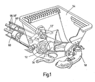
- the control arrangement shown in Fig. 2 and 3 is determined for a slurry pump according to FIG. 1.
- the sludge pump has two delivery cylinders 50,50 ', the front-side openings 52 open into a material feed tank 54 and alternately during the pressure stroke via a diverter 56 to a delivery line 58 are connectable.
- the delivery cylinders 50,50 ' are driven in a push-pull manner via hydraulic drive cylinders 5,5' and a reversible hydraulic pump 6.
- the delivery pistons 60, 60 'of the delivery cylinders 50, 50' are connected to the pistons 8, 8 'of the drive cylinders 5, 5' via a common piston rod 9, 9 '.
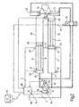
- the drive cylinder 5,5 ' are in the embodiment shown on the bottom side via hydraulic lines 11, 11' of the hydraulic circuit with the aid of Reverse pump 6 pressurized oil and are hydraulically connected to each other at its rod end via a swing oil line 12.
- the direction of movement of the drive pistons 8,8 'and thus of the common piston rod 9,9' is thereby reversed, that the direction of flow of the reversing pump 6 is reversed via a reversing device 18 containing a computer 14 and an adjusting mechanism 16.
- the reversing pump 6 has a swash plate 62, which is swiveled through its zero position during the reversal, so that the conveying direction of the pressure oil in the hydraulic lines 11, 11 'is reversed.
- the delivery rate of the reversing pump 6 can be varied by the swivel angle of the swash plate 62 at a predetermined speed of a drive motor, not shown.
- the swivel angle of the swash plate 62 can be adjusted via a remote control device 64 with the assistance of the computer 14.
- the reversal of the reversing pump and the pipe switch 56 takes place as soon as the pistons 8, 8 'of the drive cylinders 5, 5' reach their end position.
- the reversing device utilizes output signals of each of the rod-side and bottom ends of the two drive cylinders 5,5 'arranged Zylinderschaltsensoren 20,22 and 20', 22 ', which are connected on the output side to the computer 14 of the reversing device 18.
- the cylinder switch sensors respond to the drive piston 8,8 'passing by during the pumping operation and signal this event to the computer input 66,68.
- a reversing signal 76 is triggered in the reversing device with a time delay, which reverses the reversing pump 6 via the adjusting mechanism 16.
- Um variably a reversal of the diverter 56 via the directional control valve 79 and the plunger cylinder 72,72 'is also triggered by a signal 77.
- the computer 14 has a measurement and evaluation routine 40 (see Fig. 5), in which the output signals of the rod-side Zylinderschaltsensoren 20,20 'are evaluated to form a reversing signal 76,77 for the reversing pump 6 and / or the diverter 56.
- the rod-side Zylinderschaltsensoren 20,20 'with S 1 and S 2 are designated. Accordingly, the sensor positions from the bottom end of the drive cylinder with X S1 and X S2 are designated, while the useful length of the cylinder, which is calculated from the cylinder length minus the piston length, designated X Zyl . This is the maximum piston stroke.
- the positions X S1 , X S2 of the cylinder shift sensors and the effective length X Zyl are known.
- the aim of the invention is the calculation of a position X x or the associated time t x for the piston travel at the point X x , from which the reversible pump must be reversed, so that a complete piston stroke can be achieved without hard hitting the cylinder bottom.
- This position is dependent on the delivery rate, but independent of the position of the cylinder shift sensors (see Fig. 4).
- the velocity V K of the piston results from the usage length X Zyl and the stroke time t stroke as well as the acceleration and braking paths and times X Acc , X Brake , t Acc , t Brake to:
- V K X Zyl - X Accel - X brake t stroke - t Accel - t brake
- the time .DELTA.t x1 or .DELTA.t x2 will begin after passing the cylinder switch sensor. If the cylinder switch sensors are behind the tripping position, the tripping time is calculated from the beginning of the stroke.
- the triggering time can also be determined when the delivery rate changes.
- the effective length X Zyl is divided as a function of the flow rate change and to set the new speed V K of the piston for the calculation of the braking time. This is known due to the given flow rate.
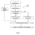
- the flow chart of the measurement and evaluation routine 40 in FIG. 5 illustrates the measurement and control operations during the piston movement in the working cylinders.
- the time t s1 and t s2 of the passing piston is determined and from this the theoretical stroke time t stroke is calculated. If in between the flow rate is changed, this affects the stroke time t stroke and thus also on the piston speed. These values are then taken into account in the calculation of the tripping time, which finally lead to the triggering of the reversing movements in the diverter switch and in the reversing pump at the time t x or ⁇ t x .
- a lead time for the stroke time is set parallel to the event measurements on the cylinder switch sensors, which independently of the measuring operations on the cylinder switch sensors via a parallel branch a reversal of the pipe switch and the reversing pump can trigger.
- the invention relates to an apparatus and a method for controlling a two-cylinder slurry pump, whose delivery pistons are actuated in push-pull mode by means of a hydraulic reversing pump 6 and via these actuated hydraulic drive cylinders.
- the delivery cylinders 50, 50 ' are connected to a delivery line 58 via a diverter 56 at each pressure stroke. At the end of each pressure stroke, a reversing operation of the reversing pump 6 and the pipe switch 56 is triggered.
- a computer-aided reversing device is provided, the measuring and Evaluation routine for metrological and / or arithmetic detection of the temporal movement of the piston on its way between the two cylinder ends and to calculate a derived triggering time for the next reversal of the reversing pump and the pipe switch has.
Landscapes
- Engineering & Computer Science (AREA)
- Mechanical Engineering (AREA)
- General Engineering & Computer Science (AREA)
- Reciprocating Pumps (AREA)
- Control Of Positive-Displacement Pumps (AREA)
- Compression-Type Refrigeration Machines With Reversible Cycles (AREA)
Description
- Die Erfindung betrifft eine Vorrichtung und ein Verfahren zur Steuerung einer Dickstoffpumpe mit zwei über stirnseitige Öffnungen in einen Materialaufgabebehälter mündenden, mittels einer hydraulischen Reversierpumpe und über diese angesteuerter hydraulischer Antriebszylinder im Gegentakt betätigbaren Förderzylindern, mit einer innerhalb des Materialaufgabebehälters angeordneten, eintrittsseitig abwechselnd an die Öffnungen der Förderzylinder anschließbaren und die jeweils andere Öffnung freigebenden und austrittsseitig mit einer Förderleitung verbundenen, hydraulisch betätigbaren Rohrweiche, wobei bei jedem Förderhub in mindestens zwei in vorgegebenen Abständen voneinander und von den stangen- und/oder bodenseitigen Enden der Antriebszylinder befindlichen Sensorpositionen das Vorbeilaufen der Kolben erfaßt und bei Beendigung eines Förderhubs ein Umsteuervorgang der Reversierpumpe und der Rohrweiche ausgelöst wird.
- Es ist eine Vorrichtung zur Steuerung einer Zweizylinder-Dickstoffpumpe dieser Art bekannt (
DE 195 42 258 ), bei welcher die Endlagen der Kolben der Antriebszylinder mittels Zylinderschaltsensoren zur Erzeugung von Endlagensignalen abgreifbar sind. Die Durchflussumkehr der Reversierpumpe ist dort über die Endlagensignale der Antriebszylinder auslösbar. In der Praxis werden die Endlagensignale üblicherweise über die beiden stangenseitigen Zylinderschaltsensoren ausgelöst. Beim Umsteuern der Reversierpumpe und der Rohrweiche kommt es immer wieder zu Problemen, wenn beispielsweise über eine Fernsteuerung unterschiedliche Fördermengen gefahren werden sollen. Dabei ist zu berücksichtigen, dass die Umsteuerung der Reversierpumpe nicht momentan erfolgt. Es bedarf vielmehr einer gewissen Umschaltzeit, innerhalb der die in einer Reversierpumpe vorhandene Schrägscheibe durchgefahren werden kann. Die Umschaltzeiten liegen bei gängigen Reversierpumpen bei ca. 0,1 sec. Bei einem Zwei-Sekunden-Hub entspricht diese Umschaltdauer etwa 5 % der Hubstrecke. Hinzu kommen weitere Verzögerungszeiten, beispielsweise für die Umschaltung der Relais, die in der gleichen Größenordnung liegen können. Dies bedeutet, dass für das Umsteuern der Reversierpumpe je nach Kolbengeschwindigkeit Strecken errechnet werden, die entweder zu einem Anschlagen der Kolben am Boden oder zu einer unvollständigen Entleerung der Zylinder führen können. Aus diesem Grund wurden schon bisher die Zylinderschaltsensoren zur Signalisierung des Kolbendurchlaufs im Bereich der Endpositionen im Abstand vom stangen- oder bodenseitigen Ende der Zylinder angeordnet. Wenn also der Kolben die Sensorposition durchläuft, steht immer noch eine Kolbenlaufstrecke für die Umschaltung zur Verfügung. Bei bekannten ZweizylinderDickstoffpumpen wurde die Position der Zylinderschaltsensoren so gewählt, dass bei maximal möglicher Kolbengeschwindigkeit eine Umsteuerung der Reversierpumpe möglich war, die gerade zu einem Bodenkontakt des Kolbens geführt hat. Wenn der Kolben langsamer läuft, führt dies aufgrund der konstanten Umschaltdauer der Reversierpumpe und der Ansprechzeit der Relais dazu, dass die Kolben während dieser Zeit nicht ganz bis zum benachbarten Boden laufen. Im Zylinder verbleibt also immer eine Restmenge Beton, die bei einem Kolbenhub nicht aus dem Zylinder herausgefördert wird. Dies kann zu einem Aushärten des Betons und zu Stopfem führen. Bei Einkreispumpen wird mit ein und derselben Hydraulikpumpe auch die Rohrweiche umgesteuert. Dies muß exakt in der Zeit erfolgen, in der die Kolben am bodenseitigen oder stangenseitigen Ende angelangt sind. Nur dann ist der Pumpendruck für die Umsteuerung der Rohrweiche ausreichend. Ein besonderes Problem der Einkreispumpe besteht also darin, dass die Zeitpunkte der Umsteuerung der Reversierpumpe, des Anhaltens der Kolben und der Umsteuerung der Rohrweiche exakt aufeinander abgestimmt werden müssen. Bei Zweikreispumpen, bei welchen die Rohrweiche über einen Druckspeicher umgesteuert wird, sind die Abstimmungsprobleme zwar etwas geringer. Gleichwohl ist jedoch auch hier durch eine geeignete Abstimmung dafür zu sorgen, dass der Kolben den Zylinder vollständig abfährt, um unerwünschte Restmengen in den Zylindern zu vermeiden. - Ausgehend hiervon liegt der Erfindung die Aufgabe zugrunde, eine Vorrichtung und ein Verfahren zur Steuerung einer Dickstoffpumpe der eingangs angegebenen Art zu entwickeln, womit ein vollständiges Entleeren der Zylinder bei jedem Kolbenhub möglich ist und dennoch ein unerwünschtes Anschlagen der Kolben an den Enden der Antriebszylinder vermieden wird.
- Eine Vorrichtung, bzw. ein Verfahren, mit den Merkmalen der Oberbegriffe der Ansprüche 1 und 6 ist z.B. aus dem Dokument
DE 42 06 576 A1 bekannt. - Zur Lösung dieser Aufgabe werden die in den Ansprüchen 1 und 6 angegebenen Merkmalskombinationen vorgeschlagen. Vorteilhafte Ausgestaltungen und Weiterbildungen der Erfindung ergeben sich aus den abhängigen Ansprüchen.
- Die erfindungsgemäße Lösung geht von dem Gedanken aus, dass mit mindestens zwei an beliebigen Stellen der Arbeitszylinder angeordneten Zylinderschaltsensoren, die im Abstand voneinander und von den beiden Endlagen angeordnet sind, eine Bewegungserfassung der Antriebskolben möglich ist, die unter Zuhilfenahme einer rechnergestützten Umsteuereinrichtung mit geeigneter Software eine vollständige Erfassung des Bewegungsablaufs der Kolben entlang der Arbeitszylinder und damit eine Lösung des vorstehend angegebenen Problems erlauben. Um dies zu erreichen, wird gemäß der Erfindung primär vorgeschlagen, dass die rechnergestützte Umsteuereinrichtung eine Mess- und Auswerteroutine zur messtechnischen und/oder rechnerischen Erfassung des zeitlichen Bewegungsablaufs der Kolben auf ihrem Weg zwischen den beiden Zylinderenden sowie zur Berechnung eines hieraus abgeleiteten Auslösezeitpunkts für eine Umsteuerung der Reversierpumpe und der Rohrweiche aufweist.
- Eine bevorzugte Ausgestaltung der Erfindung sieht vor, dass die Mess- und Auswerteroutine einen Algorithmus zur zeitlichen Erfassung des Kolbendurchgangs am Ort der Zylinderschaltsensoren sowie zur Berechnung eines hieraus abgeleiteten Auslösezeitpunkts für eine Umsteuerung der Reversierpumpe und der Rohrweiche bei jedem Kolbenhub unter Berücksichtigung einer vorgegebenen oder berechneten Bremszeit der Kolben bis zum jeweiligen Anschlag am Zylinderende aufweist. Die Bremszeit der Kolben setzt sich im Wesentlichen zusammen aus der Ansprechzeit der Umsteuerrelais und der Durchschaltzeit der Reversierpumpe.
- Bei konstanter Betriebsweise ohne Fördermengenwechsel kann jedem Zeitintervall, das als Referenzwert für die Geschwindigkeit gemessen wird, ein Auslösezeitpunkt für die Umsteuerung der Reversierpumpe und der Rohrweiche zugeordnet werden. Die Zeiterfassung kann in diesem Fall beispielsweise über den Umschaltimpuls für die Rohrweiche erfolgen. Der Abstand zwischen zwei Rohrweichenumschaltungen entspricht dann der Hubdauer. Unter Berücksichtigung der gemessenen Hubdauer wird beim Durchgang des Kolbens durch einen der beiden Zylinderschaltsensoren dann der Auslösezeitpunkt für die Umsteuerung bestimmt. Dieser Wert ist bei ein und derselben Pumpenbauart etwa konstant. Eine Besonderheit ergibt sich, wenn die Fördermenge innerhalb eines Pumpenhubs verändert wird. In diesem Fall muß die neue Fördermenge berücksichtigt und in eine entsprechende Restlaufzeit umgerechnet werden, um den exakten Auslösezeitpunkt zu ermitteln.
- Eine bevorzugte Ausgestaltung der Erfindung sieht demgemäß vor, dass die Mess- und Auswerteroutine einen Algorithmus zur Berechnung der Geschwindigkeit der Kolben auf ihrem Weg zwischen den Zylinderschaltsensoren und eines hieraus abgeleiteten Auslösezeitpunkts für die Umsteuervorgänge unter Berücksichtigung einer vorgegebenen oder berechneten Bremszeit der Kolben bis zu den jeweiligen Endanschlägen in den Zylindern aufweist.
- Eine bevorzugte Ausgestaltung der Erfindung sieht vor, dass die Mess- und Auswerteroutine auf vorzugsweise an einem Fernsteuerorgan eingestellte Vorgabewerte für die Fördermenge der Reversierpumpe anspricht und einen Algorithmus zur Bestimmung des Verlaufes der Kolbengeschwindigkeit und des daraus abgeleiteten nächsten Auslösezeitpunkts für die Umsteuervorgänge nach Maßgabe der augenblicklich eingestellten Vorgabewerte aufweist. Dabei ist es von besonderem Vorteil, wenn die Mess- und Auswerteroutine einen Algorithmus zur Bestimmung der Bremszeit oder des Bremswegs der Kolben nach Maßgabe der momentan gemessenen oder berechneten Kolbengeschwindigkeit und eines daraus abgeleiteten Auslösezeitpunkts für die Umschaltvorgänge aufweist.
- Verfahrensgemäß wird gemäß der Erfindung primär vorgeschlagen, dass der zeitliche Bewegungsablauf der Kolben auf ihrem Weg zwischen den beiden Zylinderenden gemessen und/oder berechnet und daraus der jeweils nächste Auslösezeitpunkt für die Umsteuervorgänge abgeleitet wird. Eine bevorzugte Ausgestaltung der Erfindung sieht vor, dass die Kolbendurchgänge am Ort der Zylinderschaftsensoren in zeitlicher Relation zueinander erfaßt werden und dass daraus der Auslösezeitpunkt für die jeweils folgende Umsteuerung der Reversierpumpe und der Rohrweiche unter Berücksichtigung einer vorgegebenen oder berechneten Bremszeit der Kolben bis zum jeweiligen Endanschlag am Zylinder berechnet wird. Dabei kann die Geschwindigkeit der Kolben auf ihrem Weg zwischen den ausgewählten Zylinderschaltsensoren berechnet und hieraus der nächste Zeitpunkt für die Umsteuervorgänge abgeleitet werden.
- Eine weitere bevorzugte Verfahrensweise besteht darin, dass der zeitliche Bewegungsablauf der Kolben über ferngesteuerte Vorgabewerte für die Fördermenge geändert wird und dass aus dem nach Maßgabe der Vorgabewerte berechneten Bewegungsablauf der Kolben unter Berücksichtigung einer hierdurch modifizierten Bremszeit der nächste Auslösezeitpunkt für die Umsteuervorgänge abgeleitet wird. Dazu kann es zweckmäßig sein, dass die Bremszeit oder der Bremsweg der Kolben aus der gemessenen oder berechneten momentanen Kolbengeschwindigkeit unter jeweiliger Berücksichtigung der gerätespezifischen Ansprech- und Umschaltzeiten der Reversierpumpe ermittelt und daraus der jeweils nächste Auslösezeitpunkt berechnet wird.
- Im Folgenden wird die Erfindung anhand eines in der Zeichnung in schematischer Weise dargestellten Ausführungsbeispiels näher erläutert. Es zeigen
- Fig. 1
- einen Ausschnitt aus einer Zweizylinder-Dickstoffpumpe in teilweise geschnittener schaubildlicher Darstellung;
- Fig. 2
- ein Schaltschema einer rechnergestützten Antriebshydraulik für die Zweizylinder-Dickstoffpumpe;
- Fig. 3
- einen Ausschnitt aus Fig. 2 mit einigen Maßangaben für die Berechnung eines bevorzugten Auslösezeitpunkts;
- Fig.4
- ein Geschwindigkeits-/Zeit-Diagramm der Kolbenbewegung entlang den Antriebszylindern;
- Fig. 5
- ein Flussdiagramm der Mess- und Auslöseroutine.
- Die in Fig. 2 und 3 dargestellte Steuerungsanordnung ist für eine Dickstoffpumpe entsprechend Fig. 1 bestimmt. Die Dickstoffpumpe weist zwei Förderzylinder 50,50' auf, deren stirnseitige Öffnungen 52 in einen Materialaufgabebehälter 54 münden und abwechselnd während des Druckhubs über eine Rohrweiche 56 mit einer Förderleitung 58 verbindbar sind. Die Förderzylinder 50,50' werden über hydraulische Antriebszylinder 5,5' und eine Reversierhydropumpe 6 im Gegentakt angetrieben. Zu diesem Zweck sind die Förderkolben 60,60' der Förderzylinder 50,50' mit den Kolben 8,8' der Antriebszylinder 5,5' über eine gemeinsame Kolbenstange 9,9' verbunden.
- Die Antriebszylinder 5,5' werden bei dem gezeigten Ausführungsbeispiel bodenseitig über Hydraulikleitungen 11, 11' des Hydraulikkreislaufs mit Hilfe der Reversierpumpe 6 mit Drucköl beaufschlagt und sind an ihrem stangenseitigen Ende über eine Schaukelölleitung 12 hydraulisch miteinander verbunden. Die Bewegungsrichtung der Antriebskolben 8,8' und damit der gemeinsamen Kolbenstange 9,9' wird dadurch umgekehrt, dass die Durchflussrichtung der Reversierpumpe 6 über eine einen Computer 14 und einen Verstellmechanismus 16 enthaltende Umsteuereinrichtung 18 umgekehrt wird. Die Reversierpumpe 6 weist zu diesem Zweck eine Schrägscheibe 62 auf, die bei der Umsteuerung durch ihre Nulllage hindurchgeschwenkt wird, so dass sich die Förderrichtung des Drucköls in den Hydraulikleitungen 11,11' umkehrt. Die Fördermenge der Reversierpumpe 6 kann bei vorgegebener Drehzahl eines nicht dargestellten Antriebsmotors durch den Schwenkwinkel der Schrägscheibe 62 variiert werden. Der Schwenkwinkel der Schrägscheibe 62 kann dabei über ein Fernsteuergerät 64 mit Unterstützung des Computers 14 verstellt werden.
- Die Umsteuerung der Reversierpumpe und der Rohrweiche 56 erfolgt, sobald die Kolben 8, 8' der Antriebszylinder 5, 5' ihre Endlage erreichen. Die Umsteuereinrichtung verwertet Ausgangssignale der jeweils im Abstand von den stangenseitigen und bodenseitigen Enden der beiden Antriebszylinder 5,5' angeordneten Zylinderschaltsensoren 20,22 und 20',22', die ausgangsseitig mit dem Rechner 14 der Umsteuereinrichtung 18 verbunden sind. Die Zylinderschaltsensoren sprechen auf die beim Pumpbetrieb vorbeilaufenden Antriebskolben 8,8' an und signalisieren dieses Ereignis an den Rechnereingang 66,68. Beim Auftreten der Ausgangssignale wird in der Umsteuereinrichtung zeitverzögert ein Umsteuersignal 76 ausgelöst, das die Reversierpumpe 6 über den Verstellmechanismus 16 umsteuert. Im Zuge des Umsteuervorgangs wird außerdem über ein Signal 77 eine Umsteuerung der Rohrweiche 56 über das Wegeventil 79 und die Plungerzylinder 72,72' ausgelöst. Im Normalbetrieb werden primär die Signale der stangenseitigen Zylinderschaltsensoren 20,20' zur Erzeugung eines Umsteuersignals verwendet. Dazu weist der Rechner 14 eine Mess- und Auswerteroutine 40 (vgl. Fig. 5) auf, in welcher die Ausgangssignale der stangenseitigen Zylinderschaltsensoren 20,20' unter Bildung eines Umsteuersignals 76,77 für die Reversierpumpe 6 und/oder die Rohrweiche 56 ausgewertet werden.
- Im Folgenden werden anhand der Fig. 3 und 4 die der Mess- und Auswerteroutine 40 zugrunde liegenden Berechnungsmethoden näher erläutert.
- In Fig. 3 sind die stangenseitigen Zylinderschaltsensoren 20,20' mit S1 und S2 bezeichnet. Dementsprechend sind die Sensorpositionen vom bodenseitigen Ende der Antriebszylinder aus mit XS1 und XS2 bezeichnet, während die Nutzlänge des Zylinders, die sich aus der Zylinderlänge abzüglich Kolbenlänge errechnet, mit XZyl bezeichnet ist. Hierbei handelt es sich um den maximalen Kolbenhub. Die Positionen XS1, XS2 der Zylinderschaltsensoren und die Nutzlänge XZyl sind bekannt.
- Ziel der Erfindung ist die Berechnung einer Position Xx bzw. die zugehörige Zeit tx für den Kolbendurchlauf an der Stelle Xx, von der aus die Reversierpumpe umgesteuert werden muss, damit ein vollständiger Kolbenhub ohne hartes Anschlagen am Zylinderboden erzielt werden kann. Diese Position ist abhängig von der Fördermenge, jedoch unabhängig von der Position der Zylinderschaltsensoren (vgl. Fig. 4). Die Geschwindigkeit VK des Kolbens ergibt sich aus der Nutzungslänge XZyl und der Hubzeit tHub sowie den Beschleunigungs- und Bremswegen und -zeiten XBeschl, XBrems, tBeschl, tBrems zu:

- Der Brems- oder Auslösepunkt für die Umsteuerung ergibt sich zu:


- Hieraus ergibt sich

- Der Bremszeitpunkt bestimmt sich demgemäß zu

- Eine genauere Bestimmung des Auslösezeitpunkts ist möglich, wenn zusätzlich die Informationen des Kolbendurchlaufs durch die Schalterpositionen S1 bzw. S2 hinzugenommen werden. So errechnet sich beispielsweise die Zeit zwischen dem Hubanfang und dem Schalter 1 zu

- Für die Auslösezeit vom Schalter 1 aus ergibt sich ein Wert

- Entsprechendes gilt für die Position x S
2 des Zylinderschaltsensors S2:
- Falls die Schalter S1 bzw. S2 vor dem Auslösezeitpunkt überfahren werden, wird die Zeit Δtx1 bzw. Δtx2 nach dem Überfahren des Zylinderschaltsensors beginnen. Liegen die Zylinderschaltsensoren hinter der Auslöseposition, so wird die Auslösezeit ab Hubbeginn berechnet.
- Analog zu den vorstehend beschriebenen Berechnungsmethoden kann der Auslösezeitpunkt auch bei einer Änderung der Fördermenge bestimmt werden. Dazu ist die Nutzlänge XZyl in Abhängigkeit von der Fördermengenänderung aufzuteilen und die neue Geschwindigkeit VK des Kolbens für die Berechnung der Bremszeit anzusetzen. Diese ist aufgrund der vorgegebenen Fördermenge bekannt.
- Das Flussdiagramm der Mess- und Auswerteroutine 40 in Fig. 5 veranschaulicht die Mess- und Steuerungsvorgänge während der Kolbenbewegung in den Arbeitszylindern. An den Positionen S1 und S2 der Zylinderschaltsensoren wird der Zeitpunkt ts1 und ts2 des vorbeilaufenden Kolbens ermittelt und daraus die theoretische Hubzeit tHub berechnet. Falls zwischendurch die Fördermenge geändert wird, wirkt sich dies auf die Hubzeit tHub und damit auch auf die Kolbengeschwindigkeit aus. Diese Werte werden dann berücksichtigt bei der Berechnung der Auslösezeit, die schließlich im Zeitpunkt tx bzw. Δtx zur Auslösung der Umsteuerbewegungen in der Rohrweiche und in der Reversierpumpe führen.
- Um einen sicheren Betontransport auch beim Ausfallen des einen oder anderen Zylinderschaltsensors S1,S2 zu gewährleisten, wird parallel zu den Ereignismessungen an den Zylinderschaltsensoren eine Vorhaltezeit für die Hubzeit vorgegeben, die unabhängig von den Messvorgängen an den Zylinderschaltsensoren über einen Parallelzweig eine Umsteuerung der Rohrweiche und der Reversierpumpe auslösen kann.
- Zusammenfassend ist folgendes festzuhalten: Die Erfindung bezieht sich auf eine Vorrichtung und ein Verfahren zur Steuerung einer Zweizylinder-Dickstoffpumpe, deren Förderkolben mittels einer hydraulischen Reversierpumpe 6 und über diese angesteuerter hydraulischer Antriebszylinder im Gegentakt betätigt werden. Die Förderzylinder 50, 50' werden bei jedem Druckhub über eine Rohrweiche 56 mit einer Förderleitung 58 verbunden. Bei Beendigung eines jeden Druckhubs wird ein Umsteuervorgang der Reversierpumpe 6 und der Rohrweiche 56 ausgelöst. Um auch bei Änderung der Förderleistung eine gezielte Umsteuerung der Reversierpumpe und der Rohrweiche zu erreichen, bei denen eine vollständige Entleerung der Förderzylinder ohne Kolbenschläge in den Antriebszylindern gewährleistet ist, wird gemäß der Erfindung vorgeschlagen, dass eine rechnergestützte Umsteuereinrichtung vorgesehen ist, die eine Mess- und Auswerteroutine zur messtechnischen und/oder rechnerischen Erfassung des zeitlichen Bewegungsablaufs der Kolben auf ihrem Weg zwischen den beiden Zylinderenden sowie zur Berechnung eines hieraus abgeleiteten Auslösezeitpunkts für die nächste Umsteuerung der Reversierpumpe und der Rohrweiche aufweist.
Claims (10)
- Vorrichtung zur Steuerung einer Dickstoffpumpe mit zwei über stimseitige Öffnungen (52) in einen Materialaufgabebehälter (54) mündenden, mittels mindestens einer hydraulischen Reversierpumpe (6) und über diese angesteuerter hydraulischer Antriebszylinder (5,5') im Gegentakt betätigbaren Förderzylindern (50,50'), mit einer innerhalb des Materialaufgabebehälters (54) angeordneten, eintrittsseitig abwechselnd an die Öffnungen (52) der Förderzylinder (50,50') anschließbaren und die jeweils andere Öffnung freigebenden und austrittsseitig mit einer Förderleitung (58) verbundenen, hydraulisch betätigbaren Rohrweiche (56), wobei die Antriebszylinder (5,5') an ihrem einen Ende über je eine Hydraulikleitung (11,11') mit einem Anschluß der Reversierpumpe (6) und an ihrem anderen Ende über eine Schaukelölleitung (12) miteinander hydraulisch verbunden sind, mit mindestens zwei in vorgegebenen Abständen voneinander und von den stangen- und/oder bodenseitigen Enden der Antriebszylinder (5,5') angeordneten, auf einen vorbeilaufenden Kolben (8,8') der Antriebszylinder ansprechenden Zylinderschaltsensoren (20,20';22,22'), und mit einer auf Ausgangssignale ausgewählter Zylinderschaltsensoren ansprechenden Einrichtung (18) zur Umsteuerung der Reversierpumpe (6) und der Rohrweiche (56) nach Ablauf eines jeden Kolbenhubs, dadurch gekennzeichnet, dass die rechnergestützte Umsteuereinrichtung eine Mess- und Auswerteroutine zur messtechnischen und/oder rechnerischen Erfassung des zeitlichen Bewegungsablaufs der Kolben auf ihrem Weg zwischen den beiden Zylinderenden sowie zur Berechnung eines hieraus abgeleiteten Auslösezeitpunkts für eine Umsteuerung der Reversierpumpe und der Rohrweiche aufweist
- Vorrichtung nach Anspruch 1, dadurch gekennzeichnet, dass die Mess- und Auswerteroutine einen Algorithmus zur zeitlichen Erfassung des Kolbendurchgangs am Ort der Zylinderschaltsensoren sowie zur Berechnung eines hieraus abgeleiteten Auslösezeitpunkts für eine Umsteuerung der Reversierpumpe und der Rohrweiche bei jedem Kolbenhub unter Berücksichtigung einer vorgegebenen oder berechneten Bremszeit der Kolben bis zum jeweiligen Endanschlag am Zylinder aufweist.
- Vorrichtung nach Anspruch 1 oder 2, dadurch gekennzeichnet, dass die Mess- und Auswerteroutine einen Algorithmus zur Berechnung der Geschwindigkeit der Kolben auf ihrem Weg zwischen den Zylinderschaltsensoren und eines hieraus abgeleiteten Auslösezeitpunkts für die nächsten Umsteuervorgänge unter Berücksichtigung einer vorgegebenen oder berechneten Bremszeit der Kolben bis zum jeweiligen Endanschlag am Zylinder aufweist.
- Vorrichtung nach einem der Ansprüche 1 bis 3, dadurch gekennzeichnet, dass die Mess- und Auswerteroutine auf vorzugsweise über ein Fernsteuerorgan eingestellte Vorgabewerte für die Fördermenge der Reversierpumpe anspricht und einen Algorithmus zur Bestimmung des Verlaufs der Kolbengeschwindigkeit und des daraus abgeleiteten Auslösezeitpunkts für die nächsten Umsteuervorgänge nach Maßgabe der augenblicklich eingestellten Vorgabewerte aufweist.
- Vorrichtung nach einem der Ansprüche 1 bis 4, dadurch gekennzeichnet, dass die Mess- und Auswerteroutine einen Algorithmus zur Bestimmung der Bremszeit oder des Bremswegs der Kolben nach Maßgabe der momentan gemessenen oder berechneten Kolbengeschwindigkeit und eines daraus abgeleiteten Auslösezeitpunkts für die Umschaltvorgänge aufweist.
- Verfahren zur Steuerung einer Dickstoffpumpe mit zwei über stirnseitige Öffnungen (52) in einen Materialaufgabebehälter (54) mündenden, mittels einer hydraulischen Reversierpumpe (6) und über diese angesteuerter hydraulischer Antriebszylinder (5,5') im Gegentakt betätigbaren Förderzylindern (50,50'), mit einer innerhalb des Materialaufgabebehälters (54) angeordneten, eintrittsseitig abwechselnd an die Öffnungen (52) der Förderzylinder (50,50') anschließbaren und die jeweils andere Öffnung freigebenden und austrittsseitig mit einer Förderleitung (58) verbundenen, hydraulisch betätigbaren Rohrweiche, wobei bei jedem Förderhub in mindestens zwei in vorgegebenen Abständen voneinander und von den stangen- und bodenseitigen Enden der Antriebszylinder befindlichen Sensorpositionen das Vorbeilaufen der Kolben erfaßt und ein Umsteuervorgang der Reversierpumpe (6) und/oder der Rohrweiche (56) ausgelöst wird, dadurch gekennzeichnet, dass der zeitliche Bewegungsablauf der Kolben auf ihrem Weg zwischen den beiden Zylinderenden gemessen und/oder berechnet und daraus der Auslösezeitpunkt für die jeweils nächsten Umsteuervorgänge abgeleitet wird.
- Verfahren nach Anspruch 6, dadurch gekennzeichnet, dass die Kolbendurchgänge am Ort der Zylinderschaltsensoren in zeitlicher Relation zueinander erfaßt werden und dass daraus der Auslösezeitpunkt für die jeweils folgende Umsteuerung der Reversierpumpe und der Rohrweiche unter Berücksichtigung einer vorgegebenen oder berechneten Bremszeit der Kolben bis zum jeweiligen Endanschlag am Zylinder berechnet wird.
- Verfahren nach Anspruch 6 oder 7, dadurch gekennzeichnet, dass die Geschwindigkeit der Kolben auf ihrem Weg zwischen den ausgewählten Zylinderschaltsensoren berechnet und dass hieraus der Auslösezeitpunkt für die jeweils folgende Umsteuerung der Reversierpumpe und der Rohrweiche unter Berücksichtigung einer vorgegebenen oder berechneten Bremszeit der Kolben bis zum jeweiligen Endanschlag am Zylinder abgeleitet wird.
- Verfahren nach einem der Ansprüche 6 bis 8, dadurch gekennzeichnet, dass der zeitliche Bewegungsablauf der Kolben über femgesteuerte Vorgabewerte für die Fördermenge geändert wird, und dass aus dem nach Maßgabe der Vorgabewerte berechneten Bewegungsablauf der Kolben unter Berücksichtigung einer hierdurch modifizierten Bremszeit der Auslösezeitpunkt für die folgenden Umsteuervorgänge abgeleitet wird.
- Verfahren nach einem der Ansprüche 6 bis 9, dadurch gekennzeichnet, dass die Bremszeit oder der Bremsweg der Kolben aus der gemessenen oder berechneten Kolbengeschwindigkeit unter jeweiliger Berücksichtigung der gerätespezifischen Ansprech- und Umschaltzeiten der Reversierpumpe ermittelt und daraus der jeweils nächste Auslösezeitpunkt berechnet wird.
Applications Claiming Priority (2)
| Application Number | Priority Date | Filing Date | Title |
|---|---|---|---|
| DE102004015416A DE102004015416A1 (de) | 2004-03-26 | 2004-03-26 | Vorrichtung und Verfahren zur Steuerung einer Dickstoffpumpe |
| PCT/EP2005/002893 WO2005093251A1 (de) | 2004-03-26 | 2005-03-18 | Vorrichtung und verfahren zur steuerung einer dickstoffpumpe |
Publications (2)
| Publication Number | Publication Date |
|---|---|
| EP1727979A1 EP1727979A1 (de) | 2006-12-06 |
| EP1727979B1 true EP1727979B1 (de) | 2007-07-18 |
Family
ID=34962417
Family Applications (1)
| Application Number | Title | Priority Date | Filing Date |
|---|---|---|---|
| EP05716190A Expired - Lifetime EP1727979B1 (de) | 2004-03-26 | 2005-03-18 | Vorrichtung und verfahren zur steuerung einer dickstoffpumpe |
Country Status (10)
| Country | Link |
|---|---|
| US (1) | US7581935B2 (de) |
| EP (1) | EP1727979B1 (de) |
| JP (1) | JP2007530853A (de) |
| KR (1) | KR101148579B1 (de) |
| CN (1) | CN100547239C (de) |
| AT (1) | ATE367523T1 (de) |
| DE (2) | DE102004015416A1 (de) |
| EA (1) | EA007861B1 (de) |
| ES (1) | ES2290896T3 (de) |
| WO (1) | WO2005093251A1 (de) |
Families Citing this family (30)
| Publication number | Priority date | Publication date | Assignee | Title |
|---|---|---|---|---|
| PE20130791A1 (es) * | 2010-04-07 | 2013-07-25 | Weir Minerals Netherlands Bv | Controlador de desplazamiento de fase para un sistema de bombas alternativas |
| CN102094799B (zh) * | 2010-12-28 | 2012-03-07 | 长沙中联重工科技发展股份有限公司 | 控制混凝土泵在停机后再次泵送和反泵的方法 |
| CN102410184B (zh) * | 2011-09-09 | 2012-12-26 | 中联重科股份有限公司 | 一种用于泵送装置的泵送换向控制方法、装置以及系统 |
| CN103423139B (zh) * | 2012-05-23 | 2016-04-27 | 中联重科股份有限公司 | 泵送机构及其控制方法以及混凝土泵送设备 |
| CN103423235B (zh) * | 2012-05-23 | 2015-11-25 | 中联重科股份有限公司 | 液压缸缓冲控制方法、缓冲式液压缸控制系统及液压设备 |
| CN103114980B (zh) * | 2012-06-27 | 2014-11-19 | 中联重科股份有限公司 | 双缸泵的泵送行程控制方法以及泵送设备 |
| DE102013104494B4 (de) | 2013-05-02 | 2023-11-30 | MPS-Matter Pumpsysteme GmbH | Dickstoffpumpe |
| CN103573727B (zh) * | 2013-11-07 | 2015-10-14 | 中联重科股份有限公司 | 串联油缸的换向控制方法、装置和混凝土泵送系统 |
| US9765768B2 (en) * | 2014-01-15 | 2017-09-19 | Francis Wayne Priddy | Concrete pump system and method |
| EP2913525A1 (de) * | 2014-02-26 | 2015-09-02 | Garniman SA | Hydraulisch angetriebene Balgpumpe |
| CN104265613B (zh) * | 2014-09-19 | 2016-08-24 | 中国水电基础局有限公司 | 全液压灌浆泵及其实现方法 |
| US10941762B2 (en) | 2015-01-30 | 2021-03-09 | Wagner Spray Tech Corporation | Piston limit sensing and software control for fluid application |
| JP6193291B2 (ja) * | 2015-04-13 | 2017-09-06 | 三井造船株式会社 | 燃料供給装置 |
| JP5934409B1 (ja) * | 2015-04-13 | 2016-06-15 | 三井造船株式会社 | 燃料供給装置 |
| ES2687175T3 (es) * | 2016-04-11 | 2018-10-24 | Epiroc Rock Drills Aktiebolag | Método para transmitir o transportar materiales fluidos o semifluidos por medio de una bomba de doble pistón y bomba de doble pistón para ello |
| WO2017222666A1 (en) | 2016-06-22 | 2017-12-28 | Wagner Spray Tech Corporation | Piston limit sensing and software control for fluid application |
| US12135048B2 (en) * | 2017-09-07 | 2024-11-05 | Wagner Spray Tech Corporation | Piston limit sensing for fluid application |
| WO2020017443A1 (ja) * | 2018-07-18 | 2020-01-23 | 株式会社ニチレイフーズ | 定量分割ユニット、定量分割方法及び食品製造方法 |
| US11248599B2 (en) * | 2018-09-28 | 2022-02-15 | Julio Vasquez | System for monitoring concrete pumping systems |
| US12092136B2 (en) | 2018-11-09 | 2024-09-17 | Flowserve Pte. Ltd. | Fluid exchange devices and related controls, systems, and methods |
| CA3119312A1 (en) | 2018-11-09 | 2020-05-14 | Flowserve Management Company | Fluid exchange devices and related controls, systems, and methods |
| US11891987B2 (en) * | 2018-12-14 | 2024-02-06 | Schwing Gmbh | Piston pump and method for operating a piston pump |
| DE102019212631A1 (de) | 2019-08-22 | 2021-02-25 | Putzmeister Engineering Gmbh | Verfahren zur Zustandsüberwachung einer Vorrichtung und Vorrichtung |
| MX2022005109A (es) * | 2019-12-12 | 2022-05-30 | Flowserve Man Co | Dispositivos de intercambio de fluidos y controles, sistemas y metodos relacionados. |
| DE102020200261A1 (de) * | 2020-01-10 | 2021-07-15 | Putzmeister Engineering Gmbh | Verfahren zum Betreiben einer Dickstoffpumpe und Dickstoffpumpe |
| DE102020207970A1 (de) * | 2020-06-26 | 2021-12-30 | Putzmeister Engineering Gmbh | Verfahren zum Betreiben einer Bau- und/oder Dickstoffpumpe zum Fördern von Bau- und/oder Dickstoff und Bau- und/oder Dickstoffpumpe zum Fördern von Bau- und/oder Dickstoff |
| CN111691674B (zh) * | 2020-07-20 | 2025-01-21 | 三一汽车制造有限公司 | 泵送系统和泵车 |
| CN114687980B (zh) * | 2020-12-29 | 2023-10-10 | 三一汽车制造有限公司 | 泵送设备、泵送系统及其换向参数调节方法 |
| CN113623165A (zh) * | 2021-08-14 | 2021-11-09 | 深圳市东深环保科技有限公司 | 一种双缸注浆泵 |
| DE102024103029A1 (de) * | 2024-02-02 | 2025-08-07 | Putzmeister Engineering Gmbh | Verfahren zum Betreiben eines Bau- und/oder Dickstoffpumpensystems und Bau- und/oder Dickstoffpumpensystem |
Family Cites Families (26)
| Publication number | Priority date | Publication date | Assignee | Title |
|---|---|---|---|---|
| US3663129A (en) * | 1970-09-18 | 1972-05-16 | Leon A Antosh | Concrete pump |
| JPS5864870U (ja) * | 1981-10-27 | 1983-05-02 | 株式会社新潟鐵工所 | コンクリ−トポンプのピストンストロ−ク制御装置 |
| JPS58131403A (ja) * | 1982-01-29 | 1983-08-05 | Hitachi Constr Mach Co Ltd | 油圧シリンダの緩衝装置 |
| US5388965A (en) * | 1990-10-10 | 1995-02-14 | Friedrich Wilhelm Schwing Gmbh | Sludge pump with monitoring system |
| US5106272A (en) * | 1990-10-10 | 1992-04-21 | Schwing America, Inc. | Sludge flow measuring system |
| JPH0633767B2 (ja) * | 1983-07-04 | 1994-05-02 | 三菱重工業株式会社 | スラリ−ポンプ |
| JP2575688B2 (ja) * | 1987-03-06 | 1997-01-29 | 三菱重工業株式会社 | コンクリ−トポンプの制御装置 |
| JP2585615B2 (ja) * | 1987-08-12 | 1997-02-26 | 株式会社日立製作所 | 無脈動ポンプの制御方法 |
| DE3814824A1 (de) * | 1988-05-02 | 1989-11-16 | Putzmeister Maschf | Steuerungsanordnung fuer eine zweizylinder-dickstoffpumpe |
| EP0364823B1 (de) * | 1988-10-18 | 1992-07-29 | Friedrich Wilh. Schwing GmbH | Vorrichtung zum pneumatischen Ausbringen von hydromechanisch im Dichtstrom gefördertem Beton |
| DE4215403C2 (de) * | 1991-05-16 | 2000-10-19 | Mbt Holding Ag Zuerich | Doppelkolbenpumpe zum Fördern von flüssigen Materialien, insbesondere von Beton oder Mörtel |
| JPH05196004A (ja) * | 1992-01-20 | 1993-08-06 | Komatsu Ltd | 作業機シリンダの自動クッション制御装置 |
| DE4206576B4 (de) * | 1992-03-02 | 2005-08-04 | Putzmeister Ag | Verfahren und Anordnung zur Bestimmung der Fördermenge oder des Förderstroms von mittels einer Kolbendickstoffpumpe transportiertem Fördergut |
| ES2090741T3 (es) * | 1992-03-21 | 1996-10-16 | Schwing Gmbh F | Bomba para materiales consistentes. |
| DE4209471A1 (de) * | 1992-03-24 | 1993-09-30 | Schwing Gmbh F | Dickstoffpumpe für Förderzylindern, insbesondere Zweizylinderbetonpumpe |
| DE4214109C2 (de) * | 1992-04-29 | 1994-07-28 | Abel Gmbh & Co | Feststoffpumpe |
| DE19542258A1 (de) * | 1995-11-13 | 1997-05-15 | Putzmeister Maschf | Verfahren und Vorrichtung zur Steuerung einer Zweizylinder-Dickstoffpumpe |
| JP3334525B2 (ja) * | 1996-11-14 | 2002-10-15 | 株式会社日本自動車部品総合研究所 | 可変吐出量高圧ポンプおよびそれを用いた燃料噴射装置 |
| JPH10331762A (ja) * | 1997-05-30 | 1998-12-15 | Niigata Eng Co Ltd | コンクリートポンプの運転方法及びコンクリートポンプ |
| JP3882153B2 (ja) * | 1997-06-05 | 2007-02-14 | 石川島建機株式会社 | 高粘性流体ポンプの切換制御装置 |
| JP3699596B2 (ja) * | 1997-09-11 | 2005-09-28 | 株式会社デンソー | 可変吐出量高圧ポンプ |
| KR100281932B1 (ko) * | 1998-10-10 | 2001-09-22 | 양재신 | 드라이브 실린더 유압장치 |
| DE10036202A1 (de) * | 2000-07-24 | 2002-02-07 | Putzmeister Ag | Dickstoffpumpe |
| DE10038647A1 (de) * | 2000-08-08 | 2002-02-21 | Hudelmaier Joerg | Verfahren und Vorrichtung zum gezielten Steuern einer Dickstofflampe |
| US6779983B1 (en) * | 2001-10-05 | 2004-08-24 | David A. Olson | Sludge pump with management system |
| DE10150467A1 (de) * | 2001-10-16 | 2003-04-17 | Putzmeister Ag | Dickstoffpumpe mit Fördermengenregelung |
-
2004
- 2004-03-26 DE DE102004015416A patent/DE102004015416A1/de not_active Withdrawn
-
2005
- 2005-03-18 EA EA200600260A patent/EA007861B1/ru not_active IP Right Cessation
- 2005-03-18 CN CNB2005800003795A patent/CN100547239C/zh not_active Expired - Fee Related
- 2005-03-18 US US10/558,938 patent/US7581935B2/en active Active
- 2005-03-18 WO PCT/EP2005/002893 patent/WO2005093251A1/de not_active Ceased
- 2005-03-18 AT AT05716190T patent/ATE367523T1/de not_active IP Right Cessation
- 2005-03-18 JP JP2007504319A patent/JP2007530853A/ja active Pending
- 2005-03-18 EP EP05716190A patent/EP1727979B1/de not_active Expired - Lifetime
- 2005-03-18 ES ES05716190T patent/ES2290896T3/es not_active Expired - Lifetime
- 2005-03-18 KR KR1020067009227A patent/KR101148579B1/ko not_active Expired - Fee Related
- 2005-03-18 DE DE502005001072T patent/DE502005001072D1/de not_active Expired - Lifetime
Also Published As
| Publication number | Publication date |
|---|---|
| ES2290896T3 (es) | 2008-02-16 |
| DE102004015416A1 (de) | 2005-10-13 |
| US7581935B2 (en) | 2009-09-01 |
| WO2005093251A1 (de) | 2005-10-06 |
| KR20060127381A (ko) | 2006-12-12 |
| EA007861B1 (ru) | 2007-02-27 |
| ATE367523T1 (de) | 2007-08-15 |
| EA200600260A1 (ru) | 2006-06-30 |
| KR101148579B1 (ko) | 2012-05-25 |
| JP2007530853A (ja) | 2007-11-01 |
| DE502005001072D1 (de) | 2007-08-30 |
| CN100547239C (zh) | 2009-10-07 |
| EP1727979A1 (de) | 2006-12-06 |
| CN1788160A (zh) | 2006-06-14 |
| US20060245942A1 (en) | 2006-11-02 |
Similar Documents
| Publication | Publication Date | Title |
|---|---|---|
| DE102004015416A1 (de) | Vorrichtung und Verfahren zur Steuerung einer Dickstoffpumpe | |
| EP1727980B1 (de) | Vorrichtung und verfahren zur steuerung einer zweizylinder-dickstoffpumpe | |
| EP1727981B1 (de) | Vorrichtung und verfahren zur steuerung einer dickstoffpumpe | |
| EP0562398B1 (de) | Dickstoffpumpe | |
| EP2144087B1 (de) | Verfahren und Ultraschallsensor zur Höhenbestimmung von Objekten auf einer Transporteinrichtung | |
| DE4036918A1 (de) | Verfahren zur anpassung des arbeitsverhaltens eines schlagwerks an die haerte des zerkleinerungsmaterials und einrichtung zur durchfuehrung des verfahrens | |
| EP0446206B1 (de) | Verfahren und vorrichtung zur steuerung einer zweizylinder-dickstoffpumpe | |
| WO2014195305A1 (de) | Anordnung und verfahren zum erfassen eines fördervolumens und eines förderstroms einer diskontinuierlich arbeitenden pumpe | |
| WO1993018301A1 (de) | Dickstoffpumpen-durchflussmessverfahren | |
| DE102019104218A1 (de) | Arbeitszug, umfassend eine Bodenbearbeitungsmaschine und ein weiteres Fahrzeug sowie eine automatisierte Abstandsüberwachung | |
| DE19611339A1 (de) | Verfahren zum Fördern von Werkstoffen und Vorrichtung zur Durchführung des Verfahrens | |
| EP3458201B1 (de) | Beschichtungsmittelpumpe | |
| CH667890A5 (de) | Strassenmarkierungsfahrzeug. | |
| EP2633921A1 (de) | Lackieranlage versorgt durch eine Einkolbenpumpe | |
| DE3504107C2 (de) | ||
| DE4336823A1 (de) | Vorrichtung zur elektronischen Membranlagenkontrolle | |
| DE4214109A1 (de) | Feststoffpumpe | |
| DE202004004839U1 (de) | Schmierstoff-Verteiler | |
| DE102007058118A1 (de) | Vorrichtung und Verfahren zum Ausbringen von Dickstoffen, insbesondere von Flüssigmörtel oder Flüssigbeton | |
| EP1894638B1 (de) | Verfahren zum Spülen einer Druckrohrleitung und Abwasserfördervorrichtung | |
| DE3800539A1 (de) | Schmiervorrichtung fuer walzenlader des untertagebetriebs | |
| DE3108975C2 (de) | ||
| DE4019016A1 (de) | Verfahren zur beeinflussung des betriebsverhaltens eines schlagwerks und einrichtung zur durchfuehrung des verfahrens | |
| DD205355A1 (de) | Vorrichtung zur digitalen messung der elektrodenbewegung beim widerstandsschweissen | |
| DE1527261A1 (de) | Verfahren zur Steuerung eines Manipulators einer Schmiedepresse |
Legal Events
| Date | Code | Title | Description |
|---|---|---|---|
| PUAI | Public reference made under article 153(3) epc to a published international application that has entered the european phase |
Free format text: ORIGINAL CODE: 0009012 |
|
| 17P | Request for examination filed |
Effective date: 20051013 |
|
| AK | Designated contracting states |
Kind code of ref document: A1 Designated state(s): AT BE BG CH CY CZ DE DK EE ES FI FR GB GR HU IE IS IT LI LT LU MC NL PL PT RO SE SI SK TR |
|
| GRAP | Despatch of communication of intention to grant a patent |
Free format text: ORIGINAL CODE: EPIDOSNIGR1 |
|
| GRAS | Grant fee paid |
Free format text: ORIGINAL CODE: EPIDOSNIGR3 |
|
| GRAA | (expected) grant |
Free format text: ORIGINAL CODE: 0009210 |
|
| DAX | Request for extension of the european patent (deleted) | ||
| AK | Designated contracting states |
Kind code of ref document: B1 Designated state(s): AT BE BG CH CY CZ DE DK EE ES FI FR GB GR HU IE IS IT LI LT LU MC NL PL PT RO SE SI SK TR |
|
| REG | Reference to a national code |
Ref country code: GB Ref legal event code: FG4D Free format text: NOT ENGLISH |
|
| REG | Reference to a national code |
Ref country code: CH Ref legal event code: EP |
|
| REF | Corresponds to: |
Ref document number: 502005001072 Country of ref document: DE Date of ref document: 20070830 Kind code of ref document: P |
|
| REG | Reference to a national code |
Ref country code: IE Ref legal event code: FG4D Free format text: LANGUAGE OF EP DOCUMENT: GERMAN |
|
| GBT | Gb: translation of ep patent filed (gb section 77(6)(a)/1977) |
Effective date: 20070822 |
|
| ET | Fr: translation filed | ||
| PG25 | Lapsed in a contracting state [announced via postgrant information from national office to epo] |
Ref country code: NL Free format text: LAPSE BECAUSE OF FAILURE TO SUBMIT A TRANSLATION OF THE DESCRIPTION OR TO PAY THE FEE WITHIN THE PRESCRIBED TIME-LIMIT Effective date: 20070718 Ref country code: PT Free format text: LAPSE BECAUSE OF FAILURE TO SUBMIT A TRANSLATION OF THE DESCRIPTION OR TO PAY THE FEE WITHIN THE PRESCRIBED TIME-LIMIT Effective date: 20071218 Ref country code: LT Free format text: LAPSE BECAUSE OF FAILURE TO SUBMIT A TRANSLATION OF THE DESCRIPTION OR TO PAY THE FEE WITHIN THE PRESCRIBED TIME-LIMIT Effective date: 20070718 Ref country code: BG Free format text: LAPSE BECAUSE OF FAILURE TO SUBMIT A TRANSLATION OF THE DESCRIPTION OR TO PAY THE FEE WITHIN THE PRESCRIBED TIME-LIMIT Effective date: 20071018 Ref country code: FI Free format text: LAPSE BECAUSE OF FAILURE TO SUBMIT A TRANSLATION OF THE DESCRIPTION OR TO PAY THE FEE WITHIN THE PRESCRIBED TIME-LIMIT Effective date: 20070718 Ref country code: IS Free format text: LAPSE BECAUSE OF FAILURE TO SUBMIT A TRANSLATION OF THE DESCRIPTION OR TO PAY THE FEE WITHIN THE PRESCRIBED TIME-LIMIT Effective date: 20071118 |
|
| NLV1 | Nl: lapsed or annulled due to failure to fulfill the requirements of art. 29p and 29m of the patents act | ||
| REG | Reference to a national code |
Ref country code: ES Ref legal event code: FG2A Ref document number: 2290896 Country of ref document: ES Kind code of ref document: T3 |
|
| PG25 | Lapsed in a contracting state [announced via postgrant information from national office to epo] |
Ref country code: PL Free format text: LAPSE BECAUSE OF FAILURE TO SUBMIT A TRANSLATION OF THE DESCRIPTION OR TO PAY THE FEE WITHIN THE PRESCRIBED TIME-LIMIT Effective date: 20070718 |
|
| REG | Reference to a national code |
Ref country code: IE Ref legal event code: FD4D |
|
| RAP2 | Party data changed (patent owner data changed or rights of a patent transferred) |
Owner name: PUTZMEISTER CONCRETE PUMPS GMBH |
|
| PG25 | Lapsed in a contracting state [announced via postgrant information from national office to epo] |
Ref country code: DK Free format text: LAPSE BECAUSE OF FAILURE TO SUBMIT A TRANSLATION OF THE DESCRIPTION OR TO PAY THE FEE WITHIN THE PRESCRIBED TIME-LIMIT Effective date: 20070718 Ref country code: GR Free format text: LAPSE BECAUSE OF FAILURE TO SUBMIT A TRANSLATION OF THE DESCRIPTION OR TO PAY THE FEE WITHIN THE PRESCRIBED TIME-LIMIT Effective date: 20071019 |
|
| PLBE | No opposition filed within time limit |
Free format text: ORIGINAL CODE: 0009261 |
|
| STAA | Information on the status of an ep patent application or granted ep patent |
Free format text: STATUS: NO OPPOSITION FILED WITHIN TIME LIMIT |
|
| PG25 | Lapsed in a contracting state [announced via postgrant information from national office to epo] |
Ref country code: IE Free format text: LAPSE BECAUSE OF FAILURE TO SUBMIT A TRANSLATION OF THE DESCRIPTION OR TO PAY THE FEE WITHIN THE PRESCRIBED TIME-LIMIT Effective date: 20070718 Ref country code: CZ Free format text: LAPSE BECAUSE OF FAILURE TO SUBMIT A TRANSLATION OF THE DESCRIPTION OR TO PAY THE FEE WITHIN THE PRESCRIBED TIME-LIMIT Effective date: 20070718 Ref country code: SK Free format text: LAPSE BECAUSE OF FAILURE TO SUBMIT A TRANSLATION OF THE DESCRIPTION OR TO PAY THE FEE WITHIN THE PRESCRIBED TIME-LIMIT Effective date: 20070718 |
|
| 26N | No opposition filed |
Effective date: 20080421 |
|
| PG25 | Lapsed in a contracting state [announced via postgrant information from national office to epo] |
Ref country code: RO Free format text: LAPSE BECAUSE OF FAILURE TO SUBMIT A TRANSLATION OF THE DESCRIPTION OR TO PAY THE FEE WITHIN THE PRESCRIBED TIME-LIMIT Effective date: 20070718 Ref country code: SE Free format text: LAPSE BECAUSE OF FAILURE TO SUBMIT A TRANSLATION OF THE DESCRIPTION OR TO PAY THE FEE WITHIN THE PRESCRIBED TIME-LIMIT Effective date: 20071018 |
|
| BERE | Be: lapsed |
Owner name: PUTZMEISTER A.G. Effective date: 20080331 |
|
| PG25 | Lapsed in a contracting state [announced via postgrant information from national office to epo] |
Ref country code: MC Free format text: LAPSE BECAUSE OF NON-PAYMENT OF DUE FEES Effective date: 20080331 |
|
| PG25 | Lapsed in a contracting state [announced via postgrant information from national office to epo] |
Ref country code: EE Free format text: LAPSE BECAUSE OF FAILURE TO SUBMIT A TRANSLATION OF THE DESCRIPTION OR TO PAY THE FEE WITHIN THE PRESCRIBED TIME-LIMIT Effective date: 20070718 |
|
| REG | Reference to a national code |
Ref country code: FR Ref legal event code: CJ Ref country code: FR Ref legal event code: CD |
|
| PG25 | Lapsed in a contracting state [announced via postgrant information from national office to epo] |
Ref country code: BE Free format text: LAPSE BECAUSE OF NON-PAYMENT OF DUE FEES Effective date: 20080331 |
|
| PG25 | Lapsed in a contracting state [announced via postgrant information from national office to epo] |
Ref country code: SI Free format text: LAPSE BECAUSE OF FAILURE TO SUBMIT A TRANSLATION OF THE DESCRIPTION OR TO PAY THE FEE WITHIN THE PRESCRIBED TIME-LIMIT Effective date: 20070718 |
|
| PG25 | Lapsed in a contracting state [announced via postgrant information from national office to epo] |
Ref country code: CY Free format text: LAPSE BECAUSE OF FAILURE TO SUBMIT A TRANSLATION OF THE DESCRIPTION OR TO PAY THE FEE WITHIN THE PRESCRIBED TIME-LIMIT Effective date: 20070718 |
|
| PG25 | Lapsed in a contracting state [announced via postgrant information from national office to epo] |
Ref country code: AT Free format text: LAPSE BECAUSE OF NON-PAYMENT OF DUE FEES Effective date: 20080318 |
|
| REG | Reference to a national code |
Ref country code: CH Ref legal event code: PL |
|
| PG25 | Lapsed in a contracting state [announced via postgrant information from national office to epo] |
Ref country code: CH Free format text: LAPSE BECAUSE OF NON-PAYMENT OF DUE FEES Effective date: 20090331 Ref country code: LI Free format text: LAPSE BECAUSE OF NON-PAYMENT OF DUE FEES Effective date: 20090331 |
|
| PG25 | Lapsed in a contracting state [announced via postgrant information from national office to epo] |
Ref country code: LU Free format text: LAPSE BECAUSE OF NON-PAYMENT OF DUE FEES Effective date: 20080318 Ref country code: HU Free format text: LAPSE BECAUSE OF FAILURE TO SUBMIT A TRANSLATION OF THE DESCRIPTION OR TO PAY THE FEE WITHIN THE PRESCRIBED TIME-LIMIT Effective date: 20080119 |
|
| REG | Reference to a national code |
Ref country code: GB Ref legal event code: 732E Free format text: REGISTERED BETWEEN 20110113 AND 20110119 |
|
| REG | Reference to a national code |
Ref country code: ES Ref legal event code: PC2A Owner name: PUTZMEISTER ENGINEERING GMBH Effective date: 20110610 |
|
| REG | Reference to a national code |
Ref country code: FR Ref legal event code: TP |
|
| PGFP | Annual fee paid to national office [announced via postgrant information from national office to epo] |
Ref country code: FR Payment date: 20130408 Year of fee payment: 9 Ref country code: ES Payment date: 20130314 Year of fee payment: 9 Ref country code: GB Payment date: 20130321 Year of fee payment: 9 |
|
| GBPC | Gb: european patent ceased through non-payment of renewal fee |
Effective date: 20140318 |
|
| REG | Reference to a national code |
Ref country code: FR Ref legal event code: ST Effective date: 20141128 |
|
| PG25 | Lapsed in a contracting state [announced via postgrant information from national office to epo] |
Ref country code: GB Free format text: LAPSE BECAUSE OF NON-PAYMENT OF DUE FEES Effective date: 20140318 Ref country code: FR Free format text: LAPSE BECAUSE OF NON-PAYMENT OF DUE FEES Effective date: 20140331 |
|
| REG | Reference to a national code |
Ref country code: ES Ref legal event code: FD2A Effective date: 20150424 |
|
| PG25 | Lapsed in a contracting state [announced via postgrant information from national office to epo] |
Ref country code: ES Free format text: LAPSE BECAUSE OF NON-PAYMENT OF DUE FEES Effective date: 20140319 |
|
| PGFP | Annual fee paid to national office [announced via postgrant information from national office to epo] |
Ref country code: IT Payment date: 20210323 Year of fee payment: 17 |
|
| PGFP | Annual fee paid to national office [announced via postgrant information from national office to epo] |
Ref country code: DE Payment date: 20210324 Year of fee payment: 17 Ref country code: TR Payment date: 20210312 Year of fee payment: 17 |
|
| REG | Reference to a national code |
Ref country code: DE Ref legal event code: R119 Ref document number: 502005001072 Country of ref document: DE |
|
| PG25 | Lapsed in a contracting state [announced via postgrant information from national office to epo] |
Ref country code: DE Free format text: LAPSE BECAUSE OF NON-PAYMENT OF DUE FEES Effective date: 20221001 |
|
| PG25 | Lapsed in a contracting state [announced via postgrant information from national office to epo] |
Ref country code: IT Free format text: LAPSE BECAUSE OF NON-PAYMENT OF DUE FEES Effective date: 20220318 |
|
| PG25 | Lapsed in a contracting state [announced via postgrant information from national office to epo] |
Ref country code: TR Free format text: LAPSE BECAUSE OF NON-PAYMENT OF DUE FEES Effective date: 20220318 |