EP1726514A2 - Wasserkastenstruktur für ein Fahrzeug - Google Patents
Wasserkastenstruktur für ein Fahrzeug Download PDFInfo
- Publication number
- EP1726514A2 EP1726514A2 EP06252744A EP06252744A EP1726514A2 EP 1726514 A2 EP1726514 A2 EP 1726514A2 EP 06252744 A EP06252744 A EP 06252744A EP 06252744 A EP06252744 A EP 06252744A EP 1726514 A2 EP1726514 A2 EP 1726514A2
- Authority
- EP
- European Patent Office
- Prior art keywords
- central panel
- panel
- cowl top
- vehicle
- central
- Prior art date
- Legal status (The legal status is an assumption and is not a legal conclusion. Google has not performed a legal analysis and makes no representation as to the accuracy of the status listed.)
- Granted
Links
- 238000012423 maintenance Methods 0.000 claims abstract description 8
- 238000003780 insertion Methods 0.000 claims abstract description 7
- 230000037431 insertion Effects 0.000 claims abstract description 7
- XLYOFNOQVPJJNP-UHFFFAOYSA-N water Substances O XLYOFNOQVPJJNP-UHFFFAOYSA-N 0.000 description 3
- 239000000919 ceramic Substances 0.000 description 2
- 229920003002 synthetic resin Polymers 0.000 description 2
- 239000000057 synthetic resin Substances 0.000 description 2
- 230000005540 biological transmission Effects 0.000 description 1
- 230000000694 effects Effects 0.000 description 1
- 239000011521 glass Substances 0.000 description 1
- 230000001771 impaired effect Effects 0.000 description 1
- 238000012986 modification Methods 0.000 description 1
- 230000004048 modification Effects 0.000 description 1
- 230000002093 peripheral effect Effects 0.000 description 1
- 238000007789 sealing Methods 0.000 description 1
- 238000000638 solvent extraction Methods 0.000 description 1
- 239000000725 suspension Substances 0.000 description 1
Images


Classifications
-
- B—PERFORMING OPERATIONS; TRANSPORTING
- B60—VEHICLES IN GENERAL
- B60S—SERVICING, CLEANING, REPAIRING, SUPPORTING, LIFTING, OR MANOEUVRING OF VEHICLES, NOT OTHERWISE PROVIDED FOR
- B60S1/00—Cleaning of vehicles
- B60S1/02—Cleaning windscreens, windows or optical devices
- B60S1/04—Wipers or the like, e.g. scrapers
- B60S1/0452—Position of the wipers relative to the vehicle
- B60S1/0458—Arrangement wherein the windscreen frame cooperates with the wipers
- B60S1/0463—Arrangement of the cowl
-
- B—PERFORMING OPERATIONS; TRANSPORTING
- B60—VEHICLES IN GENERAL
- B60S—SERVICING, CLEANING, REPAIRING, SUPPORTING, LIFTING, OR MANOEUVRING OF VEHICLES, NOT OTHERWISE PROVIDED FOR
- B60S1/00—Cleaning of vehicles
- B60S1/02—Cleaning windscreens, windows or optical devices
- B60S1/46—Cleaning windscreens, windows or optical devices using liquid; Windscreen washers
- B60S1/48—Liquid supply therefor
- B60S1/52—Arrangement of nozzles; Liquid spreading means
-
- B—PERFORMING OPERATIONS; TRANSPORTING
- B62—LAND VEHICLES FOR TRAVELLING OTHERWISE THAN ON RAILS
- B62D—MOTOR VEHICLES; TRAILERS
- B62D25/00—Superstructure or monocoque structure sub-units; Parts or details thereof not otherwise provided for
- B62D25/08—Front or rear portions
- B62D25/081—Cowls
Definitions
- the present invention relates to a cowl top structure for a vehicle for introducing the outside air into a vehicle compartment.
- a cowl top is a cover member located above a dashboard for partitioning an engine room and a vehicle compartment, and the cowl top has an air introducing grille.
- cowl tops having various structures in the prior art.
- Japanese Patent Laid-open No. 2003-175862 has proposed a sealing structure for a cowl top for a vehicle, wherein the cowl top is divided into two parts in the lateral direction of the vehicle, and the entry of water droplets into an engine room is prevented.
- Japanese Patent Laid-open No. Hei 8-80869 has proposed a structure of a connected portion of a divided cowl top improved in water tightness of the cowl top divided into two parts.
- a cowl top structure for a vehicle including a left side panel fixed to a vehicle body, the left side panel having a hole for insertion of a rotating shaft for a left wiper arm, a right side panel fixed to the vehicle body, the right side panel having a hole for insertion of a rotating shaft for a right wiper arm, and a central panel detachably mounted on the left and right side panels, whereby the maintenance of parts located under the cowl top can be performed by removing the central panel.
- the maintenance of parts such as engine parts located under the cowl top can be performed by removing only the central panel without the need for removal of the wiper arms and the left and right side panels. Accordingly, the maintainability can be improved.
- the central panel has a vertical wall having an air introducing grille on the side of a driver's seat in the vehicle, and a washer nozzle is provided inside of the central panel so as to open toward the air introducing grille.
- the washer nozzle is concealed behind the air introducing grille to become inconspicuous, thereby improving the marketability.
- the central panel is overlaid on the left and right side panels at portions in the vicinity of left and right ends of the central panel on the side of a vehicle compartment.
- the central panel has means for engaging the left and right side panels at the overlaid portions, and the central panel is detachably mounted through the engaging means to the left and right side panels on the side of the vehicle compartment.
- FIG. 1 is a perspective view of the vehicle including the cowl top structure according to the present invention.
- An engine and a transmission are mounted at a position shown by reference numeral 4 in an engine room covered with a bonnet (hood) 2.
- a cowl top 6 for introducing the outside air into a vehicle compartment is divided into a central panel 8, a left side panel 10, and a right side panel 12.
- a black ceramic film 15 is attached to a windshield (front glass screen) 14 at a lower portion thereof.
- the vehicle further includes a roof 16, a pair of wiper arms 18, a front grille 20, headlights 22, and a front bumper 24.
- a pair of damper housings (strut towers) 26 for supporting dampers (struts) of front suspensions are provided in the engine room.
- FIG. 2 is a schematic side view of FIG. 1, showing the structure that the upper surface of the central panel 8 of the cowl top 6 is substantially flush with the upper surface of the bonnet 2 at a central portion thereof.
- FIG. 3 is a perspective view of the cowl top 6 according to the preferred embodiment of the present invention.
- the cowl top 6 is divided into the central panel 8, the left side panel (left hinge cover) 10, and the right side panel (right hinge cover) 12.
- the left and right side panels 10 and 12 have holes 28 for insertion of rotating shafts for the respective wiper arms 18.
- the central panel 8 has a substantially inverted U-shaped cross section, and it has an upper wall 8a, a front wall 8b, a rear wall 8c on the driver side, and a mounting flange 8d.
- the central panel 8 is formed from a molded synthetic resin, and the left and right side panels 10 and 12 are also formed from a molded synthetic resin.
- the front wall 8b is inclined to the front side with respect to the vertical direction
- the rear wall 8c is inclined to the rear side with respect to the vertical direction.
- the front wall 8b has an air introducing grille 9 defining a plurality of holes
- the rear wall 8c also has an air introducing grille 11 defining a plurality of holes.
- FIG 5 there is shown a perspective view of a connected portion between the left side panel 10 and the central panel 8 as viewed from the lower side thereof.
- the left side panel 10 is fastened at a fixing portion 30 to a left fender (not shown) by a clip, engaged with a windshield lower panel (not shown) by a clip 32, and fixed by a clip 34 to a damper base (not shown) mounted on the left damper housing 26.
- the central panel 8 is partially overlaid on the left side panel 10 and fixed to the left side panel 10 by three clips 38. Further, the central panel 8 is also fixed to both the left side panel 10 and the windshield lower panel by a clip 36.
- Reference numeral 40 denotes a lid for maintenance, which is detachably mounted to the left side panel 10 by hooks 42.
- FIG. 6 is an enlarged perspective view of a part of the overlaid portion shown in FIG. 5 on the driver side
- FIG. 7 is a cross section taken along the line 7-7 in FIG. 6.
- the central panel 8 is integrally formed with a hook 44
- the left side panel 10 is integrally formed with a thin-walled portion 10a for engaging the hook 44 of the central panel 8.
- the hook 44 of the central panel 8 is closely engaged with the thin-walled portion 10a of the left side panel 10, thereby preventing possible floating of the central panel 8 from the left side panel 10 at the overlaid portion.
- the overlaid portion of the central panel 8 on the right side panel 12 has a similar configuration.
- FIG. 8 is a bottom plan view of the cowl top 6, showing the back side thereof.
- two washer nozzles 46 are provided inside of the central panel 8 of the cowl top 6 so as to open toward the air introducing grille 11 formed in the rear wall 8c of the central panel 8.
- the washer nozzles 46 are connected to rubber hoses 48, and the rubber hoses 48 are fixed to the central panel 8 by clips 50.
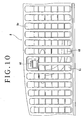
- FIG. 9 is an enlarged perspective view of one of the washer nozzles 46 and its peripheral portion
- FIG 10 is an enlarged top plan view of the central panel 8 at a portion where the washer nozzle 46 shown in FIG. 9 is located.
- FIG. 11 is a cross section taken along the line 11-11 in FIG. 8.
- each clip 54 fixed to the corresponding support 52 is engaged into a hole formed through a windshield lower panel 56, thereby fixing the central panel 8 to the windshield lower panel 56 on the driver side.
- the mounting flange 8d of the central panel 8 is formed with an engagement hole 53, and a clip is inserted in the engagement hole 53. This clip is engaged into an engagement hole formed through a dashboard upper (not shown), thereby fixing the central panel 8 at its front portion to the dashboard upper.
- the cowl top 6 is composed of three divided members, i.e., the central panel 8, the left side panel 10, and the right side panel 12. Accordingly, in performing the maintenance of parts such as engine parts located under the cowl top 6, the wiper arms 18 and the left and right side panels 10 and 12 need not be removed, but only the central panel 8 must be removed. As a result, the maintainability can be improved.
- the washer nozzles 46 are provided inside of the cowl top 6, the washer nozzles 46 are concealed behind the air introducing grille 11 to become inconspicuous, thereby improving the marketability.
- the overlaid portion of the central panel 8 on the left side panel 10 has a hook structure by the hook 44 on the driver side, and the overlaid portion of the central panel 8 on the right side panel 12 has a similar hook structure on the driver side. Accordingly, possible floating of the central panel 8 from the left and right side panels 10 and 12 at each overlaid portion on the driver side can be prevented to thereby improve the marketability.
- the front edge I of the central panel 8 has a radius of curvature smaller than that of the upper edge m of the black ceramic film 15.
- the front wall 8b and the rear wall 8c of the central panel 8 can be increased in height to thereby form sufficient air introducing holes without impairing the forward visibility.
Landscapes
- Engineering & Computer Science (AREA)
- Mechanical Engineering (AREA)
- Chemical & Material Sciences (AREA)
- Combustion & Propulsion (AREA)
- Transportation (AREA)
- Water Supply & Treatment (AREA)
- Body Structure For Vehicles (AREA)
Applications Claiming Priority (1)
| Application Number | Priority Date | Filing Date | Title |
|---|---|---|---|
| JP2005155034A JP4101819B2 (ja) | 2005-05-27 | 2005-05-27 | 車両用カウルトップ構造 |
Publications (3)
| Publication Number | Publication Date |
|---|---|
| EP1726514A2 true EP1726514A2 (de) | 2006-11-29 |
| EP1726514A3 EP1726514A3 (de) | 2007-12-19 |
| EP1726514B1 EP1726514B1 (de) | 2009-04-29 |
Family
ID=36992636
Family Applications (1)
| Application Number | Title | Priority Date | Filing Date |
|---|---|---|---|
| EP20060252744 Expired - Fee Related EP1726514B1 (de) | 2005-05-27 | 2006-05-26 | Wasserkastenstruktur für ein Fahrzeug |
Country Status (4)
| Country | Link |
|---|---|
| EP (1) | EP1726514B1 (de) |
| JP (1) | JP4101819B2 (de) |
| CN (1) | CN100429091C (de) |
| DE (1) | DE602006006499D1 (de) |
Cited By (1)
| Publication number | Priority date | Publication date | Assignee | Title |
|---|---|---|---|---|
| EP3434528A1 (de) * | 2017-07-26 | 2019-01-30 | Audi Ag | Wasserkastenabdeckung |
Families Citing this family (7)
| Publication number | Priority date | Publication date | Assignee | Title |
|---|---|---|---|---|
| JP4962171B2 (ja) * | 2007-06-29 | 2012-06-27 | トヨタ自動車株式会社 | 車体パネル構造 |
| US8888132B2 (en) * | 2012-10-09 | 2014-11-18 | GM Global Technology Operations LLC | Sealing assembly |
| CN103057381B (zh) * | 2012-12-26 | 2015-11-18 | 重庆长安汽车股份有限公司 | 一种暖风机压力室结构 |
| CN103144608B (zh) * | 2013-03-11 | 2016-02-03 | 重庆长安汽车股份有限公司 | 一种前雨刮系统安装结构 |
| JP6252335B2 (ja) * | 2014-04-22 | 2017-12-27 | 株式会社デンソー | 閉塞部材の取付構造 |
| JP6507190B2 (ja) * | 2017-03-10 | 2019-04-24 | 株式会社Subaru | 車両の前部構造 |
| JP7405880B2 (ja) | 2022-02-07 | 2023-12-26 | 本田技研工業株式会社 | カウルトップ構造 |
Citations (3)
| Publication number | Priority date | Publication date | Assignee | Title |
|---|---|---|---|---|
| FR2723051A1 (fr) | 1994-07-26 | 1996-02-02 | Valeo Systemes Essuyage Sa | Dispositif modulaire pour le lavage et l'essuyage d'un pare-brise de vehicule |
| JPH0880869A (ja) | 1994-09-13 | 1996-03-26 | Aichi Mach Ind Co Ltd | 分割式カウルトップカバーの接続部構造 |
| JP2003175862A (ja) | 2001-12-10 | 2003-06-24 | Honda Motor Co Ltd | 車両用カウルトップパネルのシール構造 |
Family Cites Families (6)
| Publication number | Priority date | Publication date | Assignee | Title |
|---|---|---|---|---|
| JPS62273142A (ja) * | 1986-05-20 | 1987-11-27 | Mazda Motor Corp | 自動車のワイパ−格納装置 |
| US5553912A (en) * | 1993-10-01 | 1996-09-10 | Chrysler Corporation | Fluid containment device |
| FR2723058B1 (fr) * | 1994-07-26 | 1996-09-06 | Valeo Systemes D Essuyage Sa | Dispositif modulaire pour le lavage et l'essuyage d'un pare-brise de vehicule |
| JPH08290783A (ja) * | 1995-04-21 | 1996-11-05 | Toyota Auto Body Co Ltd | カウルパネルカバーの取付け構造 |
| US6830288B2 (en) * | 2002-12-27 | 2004-12-14 | Collins & Aikman Automotive Company Inc. | Cowl assembly with snap-on seals |
| JP4207653B2 (ja) * | 2003-05-09 | 2009-01-14 | 三菱自動車工業株式会社 | 前部車体構造 |
-
2005
- 2005-05-27 JP JP2005155034A patent/JP4101819B2/ja not_active Expired - Fee Related
-
2006
- 2006-05-26 DE DE200660006499 patent/DE602006006499D1/de active Active
- 2006-05-26 CN CNB2006100846650A patent/CN100429091C/zh not_active Expired - Fee Related
- 2006-05-26 EP EP20060252744 patent/EP1726514B1/de not_active Expired - Fee Related
Patent Citations (3)
| Publication number | Priority date | Publication date | Assignee | Title |
|---|---|---|---|---|
| FR2723051A1 (fr) | 1994-07-26 | 1996-02-02 | Valeo Systemes Essuyage Sa | Dispositif modulaire pour le lavage et l'essuyage d'un pare-brise de vehicule |
| JPH0880869A (ja) | 1994-09-13 | 1996-03-26 | Aichi Mach Ind Co Ltd | 分割式カウルトップカバーの接続部構造 |
| JP2003175862A (ja) | 2001-12-10 | 2003-06-24 | Honda Motor Co Ltd | 車両用カウルトップパネルのシール構造 |
Cited By (1)
| Publication number | Priority date | Publication date | Assignee | Title |
|---|---|---|---|---|
| EP3434528A1 (de) * | 2017-07-26 | 2019-01-30 | Audi Ag | Wasserkastenabdeckung |
Also Published As
| Publication number | Publication date |
|---|---|
| CN100429091C (zh) | 2008-10-29 |
| JP2006327447A (ja) | 2006-12-07 |
| JP4101819B2 (ja) | 2008-06-18 |
| EP1726514A3 (de) | 2007-12-19 |
| CN1868776A (zh) | 2006-11-29 |
| EP1726514B1 (de) | 2009-04-29 |
| DE602006006499D1 (de) | 2009-06-10 |
Similar Documents
| Publication | Publication Date | Title |
|---|---|---|
| EP1726514B1 (de) | Wasserkastenstruktur für ein Fahrzeug | |
| US7322639B2 (en) | Front structure of vehicle | |
| US8002334B2 (en) | Service panel for a motor vehicle | |
| EP2540597B1 (de) | Vorderteilkonstruktion einer Fahrzeugkarosserie mit verstärktem Bereiche zum Anbau von Motorhaubescharniere | |
| US20110148148A1 (en) | Cowl cover assembly for a motor vehicle | |
| US20110084518A1 (en) | Vehicle front body structure | |
| US5127703A (en) | Front structure between an engine compartment and a passenger compartment of a vehicle body | |
| JP2007320465A (ja) | 自動車の前部構造 | |
| JP6821642B2 (ja) | カウルトップ構造 | |
| CN108068897B (zh) | 商用车的带有摄像机覆盖的可视区的驾驶室 | |
| JP5428434B2 (ja) | カウルトップガーニッシュのシール構造 | |
| JP4064673B2 (ja) | インストルメントパネル | |
| JP2020175897A (ja) | 車載カメラ用カバー構造 | |
| JP4101820B2 (ja) | 車両用カウルトップ構造 | |
| JP2001278117A (ja) | 自動車のカウル部の車体構造 | |
| JP4354332B2 (ja) | 車両のカウルルーバ | |
| JP4044106B2 (ja) | 車両用カウルトップ構造 | |
| KR100514246B1 (ko) | 자동차용 후드 인너 패널의 결합 구조 | |
| US11661019B2 (en) | Vehicle including drainage assembly | |
| JP2005067375A (ja) | カウルトップガーニッシュの水切り構造 | |
| JP6792787B2 (ja) | 車両のカウル構造 | |
| JP3865177B2 (ja) | 樹脂部品の構造 | |
| JPH11189177A (ja) | 自動車のカウル構造 | |
| JPH06127434A (ja) | 自動車のフロントボデー構造及びライトユニット構造 | |
| JP3632438B2 (ja) | 自動車のエアボックス構造 |
Legal Events
| Date | Code | Title | Description |
|---|---|---|---|
| PUAI | Public reference made under article 153(3) epc to a published international application that has entered the european phase |
Free format text: ORIGINAL CODE: 0009012 |
|
| AK | Designated contracting states |
Kind code of ref document: A2 Designated state(s): AT BE BG CH CY CZ DE DK EE ES FI FR GB GR HU IE IS IT LI LT LU LV MC NL PL PT RO SE SI SK TR |
|
| AX | Request for extension of the european patent |
Extension state: AL BA HR MK YU |
|
| PUAL | Search report despatched |
Free format text: ORIGINAL CODE: 0009013 |
|
| AK | Designated contracting states |
Kind code of ref document: A3 Designated state(s): AT BE BG CH CY CZ DE DK EE ES FI FR GB GR HU IE IS IT LI LT LU LV MC NL PL PT RO SE SI SK TR |
|
| AX | Request for extension of the european patent |
Extension state: AL BA HR MK YU |
|
| 17P | Request for examination filed |
Effective date: 20080515 |
|
| AKX | Designation fees paid |
Designated state(s): DE GB |
|
| GRAP | Despatch of communication of intention to grant a patent |
Free format text: ORIGINAL CODE: EPIDOSNIGR1 |
|
| GRAS | Grant fee paid |
Free format text: ORIGINAL CODE: EPIDOSNIGR3 |
|
| GRAA | (expected) grant |
Free format text: ORIGINAL CODE: 0009210 |
|
| AK | Designated contracting states |
Kind code of ref document: B1 Designated state(s): DE GB |
|
| REG | Reference to a national code |
Ref country code: GB Ref legal event code: FG4D |
|
| REF | Corresponds to: |
Ref document number: 602006006499 Country of ref document: DE Date of ref document: 20090610 Kind code of ref document: P |
|
| PLBE | No opposition filed within time limit |
Free format text: ORIGINAL CODE: 0009261 |
|
| STAA | Information on the status of an ep patent application or granted ep patent |
Free format text: STATUS: NO OPPOSITION FILED WITHIN TIME LIMIT |
|
| 26N | No opposition filed |
Effective date: 20100201 |
|
| REG | Reference to a national code |
Ref country code: DE Ref legal event code: R084 Ref document number: 602006006499 Country of ref document: DE |
|
| REG | Reference to a national code |
Ref country code: GB Ref legal event code: 746 Effective date: 20150217 |
|
| REG | Reference to a national code |
Ref country code: DE Ref legal event code: R084 Ref document number: 602006006499 Country of ref document: DE Effective date: 20150210 |
|
| PGFP | Annual fee paid to national office [announced via postgrant information from national office to epo] |
Ref country code: GB Payment date: 20170524 Year of fee payment: 12 Ref country code: DE Payment date: 20170523 Year of fee payment: 12 |
|
| REG | Reference to a national code |
Ref country code: DE Ref legal event code: R119 Ref document number: 602006006499 Country of ref document: DE |
|
| GBPC | Gb: european patent ceased through non-payment of renewal fee |
Effective date: 20180526 |
|
| PG25 | Lapsed in a contracting state [announced via postgrant information from national office to epo] |
Ref country code: GB Free format text: LAPSE BECAUSE OF NON-PAYMENT OF DUE FEES Effective date: 20180526 Ref country code: DE Free format text: LAPSE BECAUSE OF NON-PAYMENT OF DUE FEES Effective date: 20181201 |