EP1724227A1 - Ablenkmodul für einen Aufzug - Google Patents
Ablenkmodul für einen Aufzug Download PDFInfo
- Publication number
- EP1724227A1 EP1724227A1 EP06113722A EP06113722A EP1724227A1 EP 1724227 A1 EP1724227 A1 EP 1724227A1 EP 06113722 A EP06113722 A EP 06113722A EP 06113722 A EP06113722 A EP 06113722A EP 1724227 A1 EP1724227 A1 EP 1724227A1
- Authority
- EP
- European Patent Office
- Prior art keywords
- deflection
- deflecting
- deflection module
- housing
- support means
- Prior art date
- Legal status (The legal status is an assumption and is not a legal conclusion. Google has not performed a legal analysis and makes no representation as to the accuracy of the status listed.)
- Granted
Links
- 239000000725 suspension Substances 0.000 claims description 20
- 238000006073 displacement reaction Methods 0.000 claims description 5
- 210000001520 comb Anatomy 0.000 claims 1
- 238000010276 construction Methods 0.000 description 1
- 230000001419 dependent effect Effects 0.000 description 1
- 238000011161 development Methods 0.000 description 1
- 230000018109 developmental process Effects 0.000 description 1
- 230000000149 penetrating effect Effects 0.000 description 1
- 230000008092 positive effect Effects 0.000 description 1
Images




Classifications
-
- B—PERFORMING OPERATIONS; TRANSPORTING
- B66—HOISTING; LIFTING; HAULING
- B66B—ELEVATORS; ESCALATORS OR MOVING WALKWAYS
- B66B11/00—Main component parts of lifts in, or associated with, buildings or other structures
- B66B11/04—Driving gear ; Details thereof, e.g. seals
-
- B—PERFORMING OPERATIONS; TRANSPORTING
- B66—HOISTING; LIFTING; HAULING
- B66B—ELEVATORS; ESCALATORS OR MOVING WALKWAYS
- B66B7/00—Other common features of elevators
- B66B7/06—Arrangements of ropes or cables
- B66B7/08—Arrangements of ropes or cables for connection to the cars or cages, e.g. couplings
- B66B7/085—Belt termination devices
-
- B—PERFORMING OPERATIONS; TRANSPORTING
- B66—HOISTING; LIFTING; HAULING
- B66B—ELEVATORS; ESCALATORS OR MOVING WALKWAYS
- B66B11/00—Main component parts of lifts in, or associated with, buildings or other structures
-
- B—PERFORMING OPERATIONS; TRANSPORTING
- B66—HOISTING; LIFTING; HAULING
- B66B—ELEVATORS; ESCALATORS OR MOVING WALKWAYS
- B66B11/00—Main component parts of lifts in, or associated with, buildings or other structures
- B66B11/02—Cages, i.e. cars
-
- B—PERFORMING OPERATIONS; TRANSPORTING
- B66—HOISTING; LIFTING; HAULING
- B66B—ELEVATORS; ESCALATORS OR MOVING WALKWAYS
- B66B7/00—Other common features of elevators
Definitions
- each support means is provided a deflection on which at least one axis for rotatably supporting at least one deflection roller is.
Landscapes
- Engineering & Computer Science (AREA)
- Civil Engineering (AREA)
- Mechanical Engineering (AREA)
- Structural Engineering (AREA)
- Lift-Guide Devices, And Elevator Ropes And Cables (AREA)
- Forklifts And Lifting Vehicles (AREA)
- Motorcycle And Bicycle Frame (AREA)
- Valve-Gear Or Valve Arrangements (AREA)
- Control Of Direct Current Motors (AREA)
- Valve Device For Special Equipments (AREA)
- Cage And Drive Apparatuses For Elevators (AREA)
- Electromagnets (AREA)
Abstract
Description
- Die Erfindung betrifft ein Ablenkmodul für einen Aufzug zur Ablenkung von eine Aufzugskabine und ein Gegengewicht tragenden Tragmitteln, wobei die Tragmittel über Ablenkrollen geführt sind, die einen Richtungswechsel der Tragmittel herbeiführen gemäss der Definition des unabhängigen Patentanspruchs.
- Aus der Offenlegungsschrift
DE 23 33 120 ist ein Ablenkmodul mit zwei Ablenkrollen bekannt geworden, wobei jede Rolle ein flaches eine Aufzugskabine und ein Gegengewicht tragendes Tragmittel ablenkt. Die eine Rolle ist fest mit einer drehbaren Achse verbunden, die von einer Konsole getragen wird. Die andere Rolle ist drehbar an der Achse angeordnet. - Ein Nachteil der bekannten Einrichtung liegt darin, dass bei mehreren nebeneinander angeordneten Rollen das Ablenkmodul breit baut und bei engen Schachtverhältnissen nicht in jedem Fall verwendbar ist.
- Hier will die Erfindung Abhilfe schaffen. Die Erfindung, wie sie im unabhängigen Patentanspruch gekennzeichnet ist, löst die Aufgabe, die Nachteile der bekannten Einrichtung zu vermeiden und eine Einrichtung schaffen, die an die Schachtverhältnisse anpassbar ist.
- Vorteilhafte Weiterbildungen der Erfindung sind in den abhängigen Patentansprüchen angegeben.
- Die durch die Erfindung erreichten Vorteile sind im wesentlichen darin zu sehen, dass mit dem erfindungsgemässen, mit mehreren Ablenkelementen versehenen Ablenkmodul, insbesondere bei Riemen als Tragmittel, platzsparende Aufzugsdispositionen realisierbar sind. Weiter vorteilhaft ist, dass das Ablenkmodul leicht veränderbar ist und somit für unterschiedliche Schachtquerschnitte verwendbar ist. Neue Antriebe mit neuen und neu geführten Tragmitteln (beispielsweise Flachriemen) lassen sich ohne weiteres in bestehende Aufzugsanlagen einbauen. (Modernisierungen). Weiter vorteilhaft ist, dass mit der Anordnung des erfindungsgemässen Ablenkmoduls über der Längsachse der Gegengewichtsprojektion Schrägzug und Verdrehen der Tragmittel verhindert werden kann, was sich wiederum positiv auf die Lebensdauer der Tragmittel auswirkt.
- Beim erfindungsgemässen Ablenkmodul für einen Aufzug zur Ablenkung von eine Aufzugskabine und ein Gegengewicht tragenden Tragmitteln sind die Tragmittel über Ablenkrollen geführt, die einen Richtungswechsel der Tragmittel herbeiführen, wobei je Tragmittel ein Ablenkelement vorgesehen ist, an dem mindestens eine Achse zur drehbaren Lagerung mindestens einer Ablenkrolle angeordnet ist.
- Anhand der beiliegenden Figuren wird die vorliegende Erfindung näher erläutert.
-
- Fig. 1
eine Antriebseinheit mit Flachriemen als Tragmittel und Ablenkmodul herkömmlicher Art, - Fig. 2
eine Antriebseinheit mit Flachriemen als Tragmittel und erfindungsgemässem Ablenkmodul, - Fig. 3
eine schematische Darstellung des erfindungsgemässen Ablenkmoduls, - Fig. 4
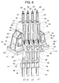
eine dreidimensionale Darstellung des erfindungsgemässen Ablenkmoduls mit integrierten Tragmittelfixpunkten, - Fig. 5
einen Querschnitt durch ein Ablenkelement des Ablenkmoduls für eine 4:1 Tragmittelführung, - Fig. 6
eine dreidimensionale Darstellung des erfindungsgemässen Ablenkmoduls für eine 2:1 Tragmittelführung, - Fig. 7
das erfindungsgemässe Ablenkmodul von unten gesehen, - Fig. 8
Einzelheiten eines Ablenkelementgehäuses und - Fig. 9
Einzelheiten einer Tragmittelendverbindung. - Fig. 1 zeigt eine Antriebseinheit 1 mit Motor 1.1, Treibscheibe 1.2, Bremse 1.3, wobei die Treibscheibe 1.2 Flachriemen 2 als Tragmittel antreibt. Die Mitte der Treibscheibe 1.2 liegt etwa in der Projektionsmitte einer Aufzugskabine 3. Die Flachriemen 2 sind über ein herkömmliches Ablenkmodul 4 geführt. Die Mitte des Ablenkmoduls 4 liegt etwa in der Projektionsmitte eines Gegengewichtes 5. Aufzugskabine 3 und Gegengewicht 5 werden von den Flachriemen 2 getragen und sind mittels der Flachriemen 2 in einem durch Schachtwände 6 begrenzten Aufzugsschacht 7 verfahrbar. Ablenkmodul 4 und Antriebseinheit stützen sich gegenseitig mittels Stangen 8.
- Die in Fig. 1 eingekreisten Stellen zeigen den Konflikt des Ablenkmoduls 4 mit der Schachtwand 6 bei schräger Anordnung, bzw. bei Anordnung des Gegengewichtes 5 in der Schachtecke. Die Ecken des herkömmlichen Ablenkmoduls 4 kollidieren mit der Schachtwand 6. Als Abhilfe kämen lediglich kostspielige Aussparungen in der Schachtwand 6 in Frage.
- Fig. 2 zeigt das erfindungsgemässe Ablenkmodul 9, das an unterschiedliche Platzverhältnisse anpassbar ist. Die Flachriemen 2 als Tragmittel werden etwa über der Längsachse der Gegengewichtsprojektion abgelenkt.
- Fig. 3 zeigt eine schematische Darstellung des erfindungsgemässen Ablenkmoduls 9, wobei Ablenkelemente 10 gegeneinander verschiebbar sind. Die Ablenkelemente 10 stützen sich gegenseitig, wobei je Seite das äusserste Ablenkelement 10 von einem Lagerschild 11 getragen wird. Der mit der gegenseitigen Verschiebbarkeit der Ablenkelemente 10 maximal erreichbare Winkel gegenüber der Rechteckkonstruktion des herkömmlichen Ablenkmoduls 4 ist mit α bezeichnet. Ein Ablenkelement 10 besteht im wesentlichen aus einem eine Achse 12 tragenden Gehäuse 13, welches zur gegenseitigen Verschiebbarkeit einerseits eine Nut 14 und andererseits einen Kamm 15 aufweist. An der Achse 12 ist eine Ablenkrolle 16 drehbar angeordnet, die geeignet ist, das Tragmittel, beispielsweise einen Flachriemen 2 zu führen und abzulenken, bzw. einen Richtungswechsel des Flachriemens 2 von beispielsweise 90° herbeizuführen. Als Tragmittel kann auch ein Keilrippenriemen oder ein Zahnriemen oder ein Seil vorgesehen sein. Wie in den Fig. 4 bis 7 gezeigt, gewährleisten Grundplatten 28 nach dem Prinzip des Parallelogrammes, dass jedes Ablenkelement 10 bzw. Gehäuse 13 um die gleiche Distanz zum benachbarten Ablenkelement 10 bzw. Gehäuse 13 verschiebbar ist.
- Fig. 4 zeigt eine dreidimensionale Darstellung des erfindungsgemässen Ablenkmoduls 9 mit integrierten Tragmittelfixpunkten 17 für eine 4:1 Tragmittelführung. Jedes Lagerschild 11 steht in Verbindung mit der jeweiligen Stange 8, wobei das Lagerschild 11 auf einem Schwingungsdämpfer 11.1 und dieser wiederum auf einer nicht dargestellten Konsole ruht. Ein Tragmittelfixpunkt 17 besteht im wesentlichen aus einer Tragmittelendverbindung 18, einem Bügel 19, einem Gewindebolzen 20 und einer Ausgleichsfeder 21. Die Tragmittelendverbindung 18 hält das Ende des Tragmittels 2 fest. Der das kastenartige Gehäuse 13 des Ablenkelementes 10 durchdringende Bügel 19 steht einerseits mit der Tragmittelendverbindung 18 und andererseits mit dem Gewindebolzen 20 in Verbindung. Die Ausgleichsfeder 21 stützt sich einerseits am Gehäuse 13 ab, andererseits stützt sich der Gewindebolzen 20 mittels Unterlagsscheiben 22 und Muttern 23 an der Ausgleichsfeder 21 ab. Für eine 4:1 Tragmittelführung sind am Ablenkmodul 9 eine erste Ablenkrolle 16.1 mit Achse 12.1 und eine zweite Ablenkrolle 16.2 mit Achse 12.2 notwendig, wobei das Tragmittel 2 wie in Fig. 5 gezeigt von der Tragmittelendverbindung 18 als Strang 2.1 auf eine erste Umlenkrolle 26 des Gegengewichtes 5, dann als Strang 2.2 auf die erste Ablenkrolle 16.1 des Ablenkmoduls 9, weiter als Strang 2.3 auf eine zweite Umlenkrolle 27 des Gegengewichtes 5, weiter als Strang 2.4 auf die zweite Ablenkrolle 16.2 des Ablenkmoduls 9 und weiter als Strang 2.5 auf die Treibscheibe 1.2 geführt ist. Das Tragmittel 2 und die erste Ablenkrolle 16.1 durchdringen den Bügel 19 des Tragmittelfixpunktes 17.
- Fig. 5 zeigt einen Querschnitt durch ein Ablenkelement 10 des Ablenkmoduls 9 für die oben erläuterte 4:1 Tragmittelführung.
- Fig. 6 zeigt eine dreidimensionale Darstellung des erfindungsgemässen Ablenkmoduls 9 für eine 2:1 oder 1:1 Tragmittelführung. Die zweite Ablenkrolle 16.2 des Ablenkmoduls 9 und die zweite Umlenkrolle 27 des Gegengewichtes 5 bzw. der Aufzugskabine 3 entfallen bei der 2:1 Tragmittelführung. Ausser der fehlenden zweiten Ablenkrolle 16.2 ist der Aufbau des Ablenkmoduls 9 identisch mit demjenigen der 4:1 Tragmittelführung. Das Tragmittel 2 ist von der Tragmittelendverbindung 18 als Strang 2.1 auf eine erste Umlenkrolle 26 des Gegengewichtes 5, dann als Strang 2.2 auf die erste Ablenkrolle 16.1 des Ablenkmoduls 9 und dann auf die Treibscheibe 1.2 geführt. Bei der 1:1 Tragmittelführung entfallen die Tragmittelfixpunkte 17 und die Umlenkrollen am Gegengewicht 5 bzw. an der Aufzugskabine 3.
- Ausser Nut 14 und Kamm 15 weist das Ablenkelement 10 einerseits Langlöcher 24 und andererseits Bohrungen 25 auf. Nicht dargestellte Schrauben durchdringen die Bohrungen 25 und die Langlöcher 24 und halten je zwei Ablenkelemente 10 fest zusammen. Die gegenseitige Verschiebbarkeit der Ablenkelemente 10 ist mittels der Langlöcher 24 gewährleistet.
- Fig. 7 zeigt das erfindungsgemässe Ablenkmodul 9 von unten gesehen, wobei jedes Ablenkelement 10 bzw. jedes Gehäuse 13 an jeder Schmalseite mit einer Grundplatte 28 verbindbar ist. Die Grundplatte 28 weist zwei mittlere Langlöcher 28.1 und zwei äussere Langlöcher 28.2 auf. Die mittleren Langlöcher 28.1 sind halb so lang wie die äusseren Langlöcher 21.2. Nicht dargestellt sind Verbindungsmittel, beispielsweise Schrauben, die die Langlöcher 28.1,28.2 und am Gehäuse 13 angeordnete Bohrungen 29 durchdringen und die Grundplatten 28 mit den Gehäusen 13 lösbar verbinden. Die Grundplatten 28 gewährleisten nach dem Prinzip des Parallelogrammes, dass jedes Ablenkelement 10 bzw. Gehäuse 13 um die gleiche Distanz zum benachbarten Ablenkelement 10 bzw. Gehäuse 13 verschiebbar ist. In Fig. 7 bilden die Grundplatten 28 zusammen mit den Ablenkelementen 10 ein Parallelogramm. Ohne Verschiebung der Ablenkelemente 10 bilden die Grundplatten 28 zusammen mit den Ablenkelementen 10 ein Rechteck.
- Fig. 8 zeigt Einzelheiten des Gehäuses 13 mit Nut 14 und Kamm 15 als Führung beim Verschieben der Gehäuse 13 gegeneinander. Mit 30 bzw. mit 31 sind Bohrungen bezeichnet, die der Aufnahme der Achse der Ablenkrolle 16.1 bzw. der Aufnahme der Achse der Ablenkrolle 16.2 dienen. Mit 32 ist eine Bohrung bezeichnet, durch die der Gewindebolzen 20 geführt ist. Der Gewindebolzen 20 ist wie in Fig. 9 gezeigt mit dem Bügel 19 verbunden, an dem wiederum der Tragmittelfixpunkt 17 angeordnet ist.
Claims (9)
- Ablenkmodul für einen Aufzug zur Ablenkung von eine Aufzugskabine und ein Gegengewicht tragenden Tragmitteln (2), wobei die Tragmittel (2) über Ablenkrollen (16) geführt sind, die einen Richtungswechsel der Tragmittel (2) herbeiführen,
dadurch gekennzeichnet,
dass je Tragmittel (2) ein Ablenkelement (10) vorgesehen ist, an dem mindestens eine Achse (12) zur drehbaren Lagerung mindestens einer Ablenkrolle (16) angeordnet ist. - Ablenkmodul nach Anspruch 1,
dadurch gekennzeichnet,
dass die Gehäuse (13) der Ablenkelemente (10) gegeneinander verschiebbar sind und von Lagerschildern (11) getragen werden. - Ablenkmodul nach Anspruch 2,
dadurch gekennzeichnet,
dass zur gegenseitigen Verschiebbarkeit der Ablenkelemente (10) am Gehäuse (13) Nuten, Kämme (15), Langlöcher (24) und Bohrungen (25) angeordnet sind. - Ablenkmodul nach Anspruch 3,
dadurch gekennzeichnet,
dass die Ablenkelemente (10) mittels Grundplatten (28) verbindbar sind, wobei die Grundplatten (28) nach dem Prinzip des Parallelogrammes gewährleisten, dass jedes Ablenkelement (10) bzw. Gehäuse (13) um die gleiche Distanz zum benachbarten Ablenkelement (10) bzw. Gehäuse (13) verschiebbar ist. - Ablenkmodul nach einem der vorhergehenden Ansprüche,
dadurch gekennzeichnet,
dass je Gehäuse (13) ein Tragmittelfixpunkt (17) zum Festhalten des Tragmittelendes vorgesehen ist. - Ablenkmodul nach Anspruch 5,
dadurch gekennzeichnet,
dass der Tragmittelfixpunkt (17) einen in das Gehäuse (13) reichenden Bügel (19) aufweist, an dem einenends eine Tragmittelendverbindung (18) angeordnet ist und der anderenends von einem Gewindebolzen (20) getragen wird, der sich mittels einer Ausgleichsfeder (21) am Gehäuse (13) abstützt. - Ablenkmodul nach einem der Ansprüche 1 bis 6,
dadurch gekennzeichnet,
dass das Ablenkelement (10) eine Ablenkrolle (16) für eine 2:1 oder 1:1 Tragmittelführung aufweist. - Ablenkmodul nach einem der Ansprüche 1 bis 6,
dadurch gekennzeichnet,
dass das Ablenkelement (10) zwei Ablenkrollen (16) für eine 4:1 Tragmittelführung aufweist. - Aufzug mit Ablenkmodul nach einem der Ansprüche 1 bis 8.
Priority Applications (2)
| Application Number | Priority Date | Filing Date | Title |
|---|---|---|---|
| EP06113722A EP1724227B1 (de) | 2005-05-19 | 2006-05-09 | Ablenkmodul für einen Aufzug |
| PL06113722T PL1724227T3 (pl) | 2005-05-19 | 2006-05-09 | Moduł odchylający do dźwigu |
Applications Claiming Priority (2)
| Application Number | Priority Date | Filing Date | Title |
|---|---|---|---|
| EP05104228 | 2005-05-19 | ||
| EP06113722A EP1724227B1 (de) | 2005-05-19 | 2006-05-09 | Ablenkmodul für einen Aufzug |
Publications (2)
| Publication Number | Publication Date |
|---|---|
| EP1724227A1 true EP1724227A1 (de) | 2006-11-22 |
| EP1724227B1 EP1724227B1 (de) | 2008-07-23 |
Family
ID=35892607
Family Applications (1)
| Application Number | Title | Priority Date | Filing Date |
|---|---|---|---|
| EP06113722A Expired - Lifetime EP1724227B1 (de) | 2005-05-19 | 2006-05-09 | Ablenkmodul für einen Aufzug |
Country Status (10)
| Country | Link |
|---|---|
| US (1) | US7261187B2 (de) |
| EP (1) | EP1724227B1 (de) |
| JP (1) | JP2006321656A (de) |
| KR (1) | KR101321151B1 (de) |
| CN (1) | CN1865113B (de) |
| AT (1) | ATE402114T1 (de) |
| CA (1) | CA2547247C (de) |
| DE (1) | DE502006001165D1 (de) |
| ES (1) | ES2310888T3 (de) |
| PL (1) | PL1724227T3 (de) |
Families Citing this family (7)
| Publication number | Priority date | Publication date | Assignee | Title |
|---|---|---|---|---|
| DE50211490D1 (de) * | 2001-11-23 | 2008-02-14 | Inventio Ag | Aufzug mit riemenartigem Übertragungsmittel, insbesondere mit Keilrippen-Riemen, als Tragmittel und/oder Treibmittel |
| US9676594B2 (en) * | 2013-08-28 | 2017-06-13 | Lml Lifts, Llc | Anti-rotation system and anti-rotation device |
| EP3074334B1 (de) * | 2013-11-25 | 2020-09-16 | Otis Elevator Company | Grundplatte für ein aufzugssystem |
| JP6118720B2 (ja) * | 2013-12-19 | 2017-04-19 | 株式会社日立製作所 | エレベーター装置 |
| EP3186184B1 (de) | 2014-08-28 | 2024-07-10 | Otis Elevator Company | Gegengewicht für ein aufzugssystem |
| KR101935634B1 (ko) * | 2016-10-27 | 2019-01-04 | 현대엘리베이터주식회사 | 엘리베이터 탄소섬유벨트의 파단 검출장치 |
| US10941020B2 (en) * | 2018-01-30 | 2021-03-09 | Otis Elevator Company | Deflector sheave bracket for offset bedplate |
Citations (4)
| Publication number | Priority date | Publication date | Assignee | Title |
|---|---|---|---|---|
| DE1208463B (de) * | 1959-11-09 | 1966-01-05 | Anglo Amer Corp South Africa | Selbsttaetige Spannungsausgleichseinrichtung fuer die Foerderseile einer Mehrseilaufzugs-einrichtung fuer Bergwerke |
| DE19839864A1 (de) * | 1998-09-02 | 1999-08-05 | Johannes Rinio | Vorrichtung zur Vertikalverlagerung von Lastaufnahmemitteln für Güter und/oder Personen |
| WO2004069715A1 (en) * | 2003-01-31 | 2004-08-19 | Otis Elevator Company | Integrated support for elevator machine, sheaves and terminations |
| EP1621508A2 (de) * | 2004-07-17 | 2006-02-01 | Inventio Ag | Einrichtung zum Aufhängen einer Kabine in einer Aufzugsanlage |
Family Cites Families (9)
| Publication number | Priority date | Publication date | Assignee | Title |
|---|---|---|---|---|
| US1915486A (en) * | 1932-01-27 | 1933-06-27 | Evans Elevator Equalizer Compa | Device for equalizing strain on hoisting ropes |
| DE2333120A1 (de) | 1973-06-29 | 1975-01-23 | Rudolf Dr Ing Vogel | Treib- und/oder umlenkrollen fuer stahlbaender als traeger von transportmitteln |
| JPH02158587A (ja) * | 1988-12-09 | 1990-06-19 | Nippon Otis Elevator Co | エレベータのシーブ配列構造 |
| JPH0761745A (ja) * | 1993-08-18 | 1995-03-07 | Otis Elevator Co | 巻き上げ式エレベーター |
| JP2729271B2 (ja) * | 1996-02-02 | 1998-03-18 | 株式会社石川精器 | コンベア装置 |
| WO2003074409A1 (en) * | 2002-03-01 | 2003-09-12 | Mitsubishi Denki Kabushiki Kaisha | Elevaltor apparatus |
| BR0317418A (pt) * | 2003-01-11 | 2005-11-08 | Jeong-Du Choi | Aparelho para equilibrar a tensão de cabos principais de elevador |
| JP5214098B2 (ja) | 2004-07-17 | 2013-06-19 | インベンテイオ・アクテイエンゲゼルシヤフト | エレベータ設備におけるケージまたは釣り合いおもりの懸架のための装置、および懸架手段の取り付けおよび保守のための方法 |
| SG119287A1 (en) * | 2004-07-17 | 2006-02-28 | Inventio Ag | Elevator installation with flat-belt-type suspension means arranged in parallel |
-
2006
- 2006-04-27 JP JP2006122977A patent/JP2006321656A/ja active Pending
- 2006-05-09 PL PL06113722T patent/PL1724227T3/pl unknown
- 2006-05-09 AT AT06113722T patent/ATE402114T1/de active
- 2006-05-09 DE DE502006001165T patent/DE502006001165D1/de not_active Expired - Lifetime
- 2006-05-09 EP EP06113722A patent/EP1724227B1/de not_active Expired - Lifetime
- 2006-05-09 ES ES06113722T patent/ES2310888T3/es not_active Expired - Lifetime
- 2006-05-17 CA CA2547247A patent/CA2547247C/en not_active Expired - Lifetime
- 2006-05-17 CN CN2006100818754A patent/CN1865113B/zh not_active Expired - Fee Related
- 2006-05-19 US US11/419,223 patent/US7261187B2/en not_active Expired - Lifetime
- 2006-05-19 KR KR1020060044881A patent/KR101321151B1/ko not_active Expired - Fee Related
Patent Citations (4)
| Publication number | Priority date | Publication date | Assignee | Title |
|---|---|---|---|---|
| DE1208463B (de) * | 1959-11-09 | 1966-01-05 | Anglo Amer Corp South Africa | Selbsttaetige Spannungsausgleichseinrichtung fuer die Foerderseile einer Mehrseilaufzugs-einrichtung fuer Bergwerke |
| DE19839864A1 (de) * | 1998-09-02 | 1999-08-05 | Johannes Rinio | Vorrichtung zur Vertikalverlagerung von Lastaufnahmemitteln für Güter und/oder Personen |
| WO2004069715A1 (en) * | 2003-01-31 | 2004-08-19 | Otis Elevator Company | Integrated support for elevator machine, sheaves and terminations |
| EP1621508A2 (de) * | 2004-07-17 | 2006-02-01 | Inventio Ag | Einrichtung zum Aufhängen einer Kabine in einer Aufzugsanlage |
Also Published As
| Publication number | Publication date |
|---|---|
| KR20060120467A (ko) | 2006-11-27 |
| US7261187B2 (en) | 2007-08-28 |
| ATE402114T1 (de) | 2008-08-15 |
| DE502006001165D1 (de) | 2008-09-04 |
| ES2310888T3 (es) | 2009-01-16 |
| CN1865113B (zh) | 2010-05-12 |
| PL1724227T3 (pl) | 2009-01-30 |
| EP1724227B1 (de) | 2008-07-23 |
| KR101321151B1 (ko) | 2013-11-25 |
| US20060260879A1 (en) | 2006-11-23 |
| CN1865113A (zh) | 2006-11-22 |
| CA2547247C (en) | 2016-03-15 |
| JP2006321656A (ja) | 2006-11-30 |
| CA2547247A1 (en) | 2006-11-19 |
Similar Documents
| Publication | Publication Date | Title |
|---|---|---|
| EP1621509B1 (de) | Anordnung von einer Antriebsmaschine einer Aufzugsanlage | |
| EP1640308B1 (de) | Anordnung von Antriebsmaschine einer Aufzuganlage | |
| EP0763495A1 (de) | Maschinenrahmen | |
| EP3052422B1 (de) | Aufzuganlage | |
| EP2082983B1 (de) | Aufzugsanlage | |
| EP1935830A1 (de) | Aufzug mit zwei übereinander liegenden Aufzugskabinen in einem Schacht | |
| DE3907541A1 (de) | Seilaufhaengung eines aufzugs | |
| EP1724227B1 (de) | Ablenkmodul für einen Aufzug | |
| EP1700809B1 (de) | Aufzuganlage | |
| WO2002068307A1 (de) | Anordnung für gewichtsausgleichelemente | |
| EP2714567B1 (de) | Antriebsrahmen in einer aufzugsanlage | |
| EP2492232A1 (de) | Spannvorrichtung in einer Aufzugsanlage | |
| EP1531139A1 (de) | Maschinenrahmenlose Antriebseinheit für einen Aufzug | |
| DE19931396C2 (de) | Seilzug-Aufzuganlage | |
| EP1790608A1 (de) | Aufzugsanlage mit Einrichtung zur Kompensation des Gewichtsunterschieds zwischen den Kabinentrumen und den Gegengewichtstrumen der Tragmittel und Verfahren zur Realisierung einer solchen Kompensation | |
| DE10319731A1 (de) | Aufzug | |
| DE202014102110U1 (de) | Aufzuganlage | |
| DE112005000398T5 (de) | Maschinenraumloser Aufzug | |
| EP1588978B1 (de) | Antrieb für eine Aufzugsanlage | |
| EP4344430B1 (de) | Maschinenraumloses aufzugssystem | |
| DE19963297B4 (de) | Aufzug | |
| EP1621508A2 (de) | Einrichtung zum Aufhängen einer Kabine in einer Aufzugsanlage | |
| EP1045811B1 (de) | Seil-aufzug mit treibscheibe | |
| EP1935826B1 (de) | Aufzugssystem | |
| EP3235770B1 (de) | Verfahren zur nachrüstung eines aufzugs und korrespondierender aufzug |
Legal Events
| Date | Code | Title | Description |
|---|---|---|---|
| PUAI | Public reference made under article 153(3) epc to a published international application that has entered the european phase |
Free format text: ORIGINAL CODE: 0009012 |
|
| AK | Designated contracting states |
Kind code of ref document: A1 Designated state(s): AT BE BG CH CY CZ DE DK EE ES FI FR GB GR HU IE IS IT LI LT LU LV MC NL PL PT RO SE SI SK TR |
|
| AX | Request for extension of the european patent |
Extension state: AL BA HR MK YU |
|
| 17P | Request for examination filed |
Effective date: 20070515 |
|
| AKX | Designation fees paid |
Designated state(s): AT BE BG CH CY CZ DE DK EE ES FI FR GB GR HU IE IS IT LI LT LU LV MC NL PL PT RO SE SI SK TR |
|
| 17Q | First examination report despatched |
Effective date: 20070726 |
|
| GRAP | Despatch of communication of intention to grant a patent |
Free format text: ORIGINAL CODE: EPIDOSNIGR1 |
|
| GRAS | Grant fee paid |
Free format text: ORIGINAL CODE: EPIDOSNIGR3 |
|
| GRAA | (expected) grant |
Free format text: ORIGINAL CODE: 0009210 |
|
| AK | Designated contracting states |
Kind code of ref document: B1 Designated state(s): AT BE BG CH CY CZ DE DK EE ES FI FR GB GR HU IE IS IT LI LT LU LV MC NL PL PT RO SE SI SK TR |
|
| REG | Reference to a national code |
Ref country code: GB Ref legal event code: FG4D Free format text: NOT ENGLISH |
|
| REG | Reference to a national code |
Ref country code: CH Ref legal event code: EP |
|
| REG | Reference to a national code |
Ref country code: IE Ref legal event code: FG4D Free format text: LANGUAGE OF EP DOCUMENT: GERMAN |
|
| REF | Corresponds to: |
Ref document number: 502006001165 Country of ref document: DE Date of ref document: 20080904 Kind code of ref document: P |
|
| REG | Reference to a national code |
Ref country code: SE Ref legal event code: TRGR |
|
| REG | Reference to a national code |
Ref country code: ES Ref legal event code: FG2A Ref document number: 2310888 Country of ref document: ES Kind code of ref document: T3 |
|
| PG25 | Lapsed in a contracting state [announced via postgrant information from national office to epo] |
Ref country code: IS Free format text: LAPSE BECAUSE OF FAILURE TO SUBMIT A TRANSLATION OF THE DESCRIPTION OR TO PAY THE FEE WITHIN THE PRESCRIBED TIME-LIMIT Effective date: 20081123 Ref country code: LT Free format text: LAPSE BECAUSE OF FAILURE TO SUBMIT A TRANSLATION OF THE DESCRIPTION OR TO PAY THE FEE WITHIN THE PRESCRIBED TIME-LIMIT Effective date: 20080723 |
|
| REG | Reference to a national code |
Ref country code: PL Ref legal event code: T3 |
|
| PG25 | Lapsed in a contracting state [announced via postgrant information from national office to epo] |
Ref country code: BG Free format text: LAPSE BECAUSE OF FAILURE TO SUBMIT A TRANSLATION OF THE DESCRIPTION OR TO PAY THE FEE WITHIN THE PRESCRIBED TIME-LIMIT Effective date: 20081023 Ref country code: LV Free format text: LAPSE BECAUSE OF FAILURE TO SUBMIT A TRANSLATION OF THE DESCRIPTION OR TO PAY THE FEE WITHIN THE PRESCRIBED TIME-LIMIT Effective date: 20080723 Ref country code: SI Free format text: LAPSE BECAUSE OF FAILURE TO SUBMIT A TRANSLATION OF THE DESCRIPTION OR TO PAY THE FEE WITHIN THE PRESCRIBED TIME-LIMIT Effective date: 20080723 Ref country code: PT Free format text: LAPSE BECAUSE OF FAILURE TO SUBMIT A TRANSLATION OF THE DESCRIPTION OR TO PAY THE FEE WITHIN THE PRESCRIBED TIME-LIMIT Effective date: 20081223 |
|
| REG | Reference to a national code |
Ref country code: IE Ref legal event code: FD4D |
|
| PG25 | Lapsed in a contracting state [announced via postgrant information from national office to epo] |
Ref country code: DK Free format text: LAPSE BECAUSE OF FAILURE TO SUBMIT A TRANSLATION OF THE DESCRIPTION OR TO PAY THE FEE WITHIN THE PRESCRIBED TIME-LIMIT Effective date: 20080723 Ref country code: EE Free format text: LAPSE BECAUSE OF FAILURE TO SUBMIT A TRANSLATION OF THE DESCRIPTION OR TO PAY THE FEE WITHIN THE PRESCRIBED TIME-LIMIT Effective date: 20080723 Ref country code: IE Free format text: LAPSE BECAUSE OF FAILURE TO SUBMIT A TRANSLATION OF THE DESCRIPTION OR TO PAY THE FEE WITHIN THE PRESCRIBED TIME-LIMIT Effective date: 20080723 |
|
| PG25 | Lapsed in a contracting state [announced via postgrant information from national office to epo] |
Ref country code: SK Free format text: LAPSE BECAUSE OF FAILURE TO SUBMIT A TRANSLATION OF THE DESCRIPTION OR TO PAY THE FEE WITHIN THE PRESCRIBED TIME-LIMIT Effective date: 20080723 Ref country code: CZ Free format text: LAPSE BECAUSE OF FAILURE TO SUBMIT A TRANSLATION OF THE DESCRIPTION OR TO PAY THE FEE WITHIN THE PRESCRIBED TIME-LIMIT Effective date: 20080723 Ref country code: RO Free format text: LAPSE BECAUSE OF FAILURE TO SUBMIT A TRANSLATION OF THE DESCRIPTION OR TO PAY THE FEE WITHIN THE PRESCRIBED TIME-LIMIT Effective date: 20080723 |
|
| PLBE | No opposition filed within time limit |
Free format text: ORIGINAL CODE: 0009261 |
|
| STAA | Information on the status of an ep patent application or granted ep patent |
Free format text: STATUS: NO OPPOSITION FILED WITHIN TIME LIMIT |
|
| 26N | No opposition filed |
Effective date: 20090424 |
|
| PG25 | Lapsed in a contracting state [announced via postgrant information from national office to epo] |
Ref country code: MC Free format text: LAPSE BECAUSE OF NON-PAYMENT OF DUE FEES Effective date: 20090531 |
|
| PG25 | Lapsed in a contracting state [announced via postgrant information from national office to epo] |
Ref country code: GR Free format text: LAPSE BECAUSE OF FAILURE TO SUBMIT A TRANSLATION OF THE DESCRIPTION OR TO PAY THE FEE WITHIN THE PRESCRIBED TIME-LIMIT Effective date: 20081024 |
|
| PG25 | Lapsed in a contracting state [announced via postgrant information from national office to epo] |
Ref country code: LU Free format text: LAPSE BECAUSE OF NON-PAYMENT OF DUE FEES Effective date: 20090509 |
|
| PG25 | Lapsed in a contracting state [announced via postgrant information from national office to epo] |
Ref country code: HU Free format text: LAPSE BECAUSE OF FAILURE TO SUBMIT A TRANSLATION OF THE DESCRIPTION OR TO PAY THE FEE WITHIN THE PRESCRIBED TIME-LIMIT Effective date: 20090124 |
|
| PG25 | Lapsed in a contracting state [announced via postgrant information from national office to epo] |
Ref country code: CY Free format text: LAPSE BECAUSE OF FAILURE TO SUBMIT A TRANSLATION OF THE DESCRIPTION OR TO PAY THE FEE WITHIN THE PRESCRIBED TIME-LIMIT Effective date: 20080723 |
|
| REG | Reference to a national code |
Ref country code: FR Ref legal event code: PLFP Year of fee payment: 11 |
|
| REG | Reference to a national code |
Ref country code: FR Ref legal event code: PLFP Year of fee payment: 12 |
|
| PGFP | Annual fee paid to national office [announced via postgrant information from national office to epo] |
Ref country code: NL Payment date: 20170519 Year of fee payment: 12 |
|
| PGFP | Annual fee paid to national office [announced via postgrant information from national office to epo] |
Ref country code: FR Payment date: 20170523 Year of fee payment: 12 Ref country code: GB Payment date: 20170519 Year of fee payment: 12 Ref country code: CH Payment date: 20170519 Year of fee payment: 12 Ref country code: DE Payment date: 20170523 Year of fee payment: 12 |
|
| PGFP | Annual fee paid to national office [announced via postgrant information from national office to epo] |
Ref country code: IT Payment date: 20170526 Year of fee payment: 12 Ref country code: BE Payment date: 20170519 Year of fee payment: 12 Ref country code: ES Payment date: 20170628 Year of fee payment: 12 Ref country code: AT Payment date: 20170522 Year of fee payment: 12 Ref country code: FI Payment date: 20170511 Year of fee payment: 12 Ref country code: SE Payment date: 20170519 Year of fee payment: 12 |
|
| PGFP | Annual fee paid to national office [announced via postgrant information from national office to epo] |
Ref country code: TR Payment date: 20170427 Year of fee payment: 12 |
|
| PGFP | Annual fee paid to national office [announced via postgrant information from national office to epo] |
Ref country code: PL Payment date: 20170502 Year of fee payment: 12 |
|
| REG | Reference to a national code |
Ref country code: DE Ref legal event code: R119 Ref document number: 502006001165 Country of ref document: DE |
|
| REG | Reference to a national code |
Ref country code: CH Ref legal event code: PL |
|
| REG | Reference to a national code |
Ref country code: SE Ref legal event code: EUG Ref country code: NL Ref legal event code: MM Effective date: 20180601 |
|
| REG | Reference to a national code |
Ref country code: AT Ref legal event code: MM01 Ref document number: 402114 Country of ref document: AT Kind code of ref document: T Effective date: 20180509 |
|
| GBPC | Gb: european patent ceased through non-payment of renewal fee |
Effective date: 20180509 |
|
| REG | Reference to a national code |
Ref country code: BE Ref legal event code: MM Effective date: 20180531 |
|
| PG25 | Lapsed in a contracting state [announced via postgrant information from national office to epo] |
Ref country code: SE Free format text: LAPSE BECAUSE OF NON-PAYMENT OF DUE FEES Effective date: 20180510 Ref country code: FI Free format text: LAPSE BECAUSE OF NON-PAYMENT OF DUE FEES Effective date: 20180509 Ref country code: AT Free format text: LAPSE BECAUSE OF NON-PAYMENT OF DUE FEES Effective date: 20180509 |
|
| PG25 | Lapsed in a contracting state [announced via postgrant information from national office to epo] |
Ref country code: CH Free format text: LAPSE BECAUSE OF NON-PAYMENT OF DUE FEES Effective date: 20180531 Ref country code: LI Free format text: LAPSE BECAUSE OF NON-PAYMENT OF DUE FEES Effective date: 20180531 |
|
| PG25 | Lapsed in a contracting state [announced via postgrant information from national office to epo] |
Ref country code: FR Free format text: LAPSE BECAUSE OF NON-PAYMENT OF DUE FEES Effective date: 20180531 Ref country code: GB Free format text: LAPSE BECAUSE OF NON-PAYMENT OF DUE FEES Effective date: 20180509 Ref country code: DE Free format text: LAPSE BECAUSE OF NON-PAYMENT OF DUE FEES Effective date: 20181201 Ref country code: NL Free format text: LAPSE BECAUSE OF NON-PAYMENT OF DUE FEES Effective date: 20180601 Ref country code: IT Free format text: LAPSE BECAUSE OF NON-PAYMENT OF DUE FEES Effective date: 20180509 |
|
| PG25 | Lapsed in a contracting state [announced via postgrant information from national office to epo] |
Ref country code: BE Free format text: LAPSE BECAUSE OF NON-PAYMENT OF DUE FEES Effective date: 20180531 |
|
| REG | Reference to a national code |
Ref country code: ES Ref legal event code: FD2A Effective date: 20190913 |
|
| PG25 | Lapsed in a contracting state [announced via postgrant information from national office to epo] |
Ref country code: ES Free format text: LAPSE BECAUSE OF NON-PAYMENT OF DUE FEES Effective date: 20180510 |
|
| PG25 | Lapsed in a contracting state [announced via postgrant information from national office to epo] |
Ref country code: PL Free format text: LAPSE BECAUSE OF NON-PAYMENT OF DUE FEES Effective date: 20180509 |
|
| PG25 | Lapsed in a contracting state [announced via postgrant information from national office to epo] |
Ref country code: TR Free format text: LAPSE BECAUSE OF NON-PAYMENT OF DUE FEES Effective date: 20180509 |