EP1724176B1 - Einrichtung zur gelenkigen Verbindung von Eisenbahnfahrzeugen - Google Patents
Einrichtung zur gelenkigen Verbindung von Eisenbahnfahrzeugen Download PDFInfo
- Publication number
- EP1724176B1 EP1724176B1 EP06110906A EP06110906A EP1724176B1 EP 1724176 B1 EP1724176 B1 EP 1724176B1 EP 06110906 A EP06110906 A EP 06110906A EP 06110906 A EP06110906 A EP 06110906A EP 1724176 B1 EP1724176 B1 EP 1724176B1
- Authority
- EP
- European Patent Office
- Prior art keywords
- longitudinal direction
- joint
- displacement
- joint half
- forces
- Prior art date
- Legal status (The legal status is an assumption and is not a legal conclusion. Google has not performed a legal analysis and makes no representation as to the accuracy of the status listed.)
- Expired - Lifetime
Links
Images


Classifications
-
- B—PERFORMING OPERATIONS; TRANSPORTING
- B61—RAILWAYS
- B61D—BODY DETAILS OR KINDS OF RAILWAY VEHICLES
- B61D3/00—Wagons or vans
- B61D3/10—Articulated vehicles
-
- B—PERFORMING OPERATIONS; TRANSPORTING
- B61—RAILWAYS
- B61G—COUPLINGS; DRAUGHT AND BUFFING APPLIANCES
- B61G5/00—Couplings for special purposes not otherwise provided for
- B61G5/02—Couplings for special purposes not otherwise provided for for coupling articulated trains, locomotives and tenders or the bogies of a vehicle; Coupling by means of a single coupling bar; Couplings preventing or limiting relative lateral movement of vehicles
Definitions
- the invention relates to a device for the articulated connection of supported on a common bogie car bodies of railway vehicles, which has fixed to each car body hinge halves, which allow rotation about one or more axes and / or a displacement along one or more axes, wherein at least one Joint half is designed such that this joint half allows a certain displaceability of the two bodies against each other in the longitudinal direction under certain operating circumstances.
- a common construction is that the two car bodies are supported on a bogie via a pair of spring elements on the bogie.
- the articulated connection of both car bodies and the transmission of forces and moments between the two car bodies takes place via a joint, which usually consists of an inner joint, an outer joint and a spherical bearing arranged therebetween.
- This design is used, for example, in railcar trains of the class 642 and 425 of the Irish Bahn AG and is, inter alia, in DE 196 38 763 C2 described.
- the joints used in the vehicle longitudinal direction allow no or only a small, limited by the construction of Sphotrolagers displaceability of the two car bodies against each other.
- EP 1 312 527 B1 and DE 101 53 460 A1 Joint designs are described in which an articulated arm or both articulated arms a shift in Allow vehicle longitudinal direction, as in the articulated arms energy-absorbing surge protection are integrated.
- a mobility within the joint components may also be desirable for other reasons, for example, because resilient elements are to be arranged in the power flow.
- a guide is required between the mutually displaceable parts, which also serves to transmit forces in the vertical direction.
- tensile and compressive forces in the longitudinal direction are usually transmitted via different components.
- the invention has for its object to improve a device of the generic type, which is formed for any reasons for longitudinal displacement, with respect to the longitudinal guidance and the transmission of forces in the vehicle longitudinal direction.
- This object is achieved in accordance with the invention in that the transmission of the compressive forces in the longitudinal direction takes place via the at least one articulated half designed for displaceability without the involvement of components connected to one another by fastening means (eg screws) and this articulated half for transmitting the compressive forces in the longitudinal direction via a pressure piece, which is guided within a lid in the longitudinal direction.
- fastening means eg screws
- Fig. 1 to 3 show a first embodiment of the invention, in Fig. 3 in perspective view.
- Fig. 1 is the associated side view, partially in section along the line B - B in Fig. 2 , In the Fig. 2
- the top view shown in the lower half of the figure shows the section along the line C - C in Fig. 1
- the 4 and 5 each show individual parts of the joint design Fig. 1 to 3 on an enlarged scale.
- the transmission of compressive forces in the longitudinal direction takes place in a form-fitting manner via any force transmission member 7 (shown here by way of example as a helical spring) directly on the cup-shaped flange 8 in its rear part and from there into the carbody 1A, to which the flange 8 by fastening means 4A is releasably attached.
- the transmission of the tensile forces takes place over the surfaces 5.2 of the pressure piece 5 on the surface 9.2 of in Fig. 5
- For safe transmission of forces from the cover 9 on the flange 8 of the cover 9 is located with its surfaces 9.3 to corresponding mating surfaces of the flange 8 at.
- an intermediate piece 11 is arranged between the force transmission member 7 and the cup-shaped flange 8 as a further component which allows a tolerance compensation in the longitudinal direction, for example, characterized in that the intermediate piece 11 is arranged by means of fine thread in the flange 8.
- the advantage of the invention is ensured, according to which the transmission of the compressive forces does not take place via hinge components, which are clamped together by fastening means.
- the fine thread between the flange 8 and the intermediate piece 11 is not the bracing of the components against each other. This bracing is done rather in the basis of Fig. 1 to 3 described manner by the fastening means 10 between the lid 9 and the flange. 8
- a displaceability is provided only in a joint half, in which the pressure piece 5, the cup-shaped flange 8 and the lid 9 having outer joint.
- the inner joint 2 than other joint half in Execute a sense of displacement or both halves of the joint, so the outer joint and the inner joint 2 to make according to this mobility.
Landscapes
- Engineering & Computer Science (AREA)
- Mechanical Engineering (AREA)
- Transportation (AREA)
- Pivots And Pivotal Connections (AREA)
- Electric Propulsion And Braking For Vehicles (AREA)
- Forklifts And Lifting Vehicles (AREA)
- Agricultural Machines (AREA)
- Vehicle Cleaning, Maintenance, Repair, Refitting, And Outriggers (AREA)
Description
- Die Erfindung betrifft eine Einrichtung zur gelenkigen Verbindung von auf einem gemeinsamen Drehgestell abgestützten Wagenkästen von Eisenbahnfahrzeugen, welche an jeweils einem Wagenkasten festgelegte Gelenkhälften aufweist, die eine Verdrehung um eine oder mehrere Achsen und/oder eine Verschiebung entlang einer oder mehrerer Achsen ermöglichen, wobei mindestens eine Gelenkhälfte derart ausgebildet ist, dass diese Gelenkhälfte unter bestimmten Betriebsumständen eine Verschieblichkeit der beiden Wagenkästen gegeneinander in Längsrichtung ermöglicht.
- Solche Einrichtungen zur gelenkigen Verbindung von Wagenkästen von Eisenbahnfahrzeugen gehen beispielsweise aus den Druckschriften
FR-A-2111470 EP-A-151905 DE 24 488 89 A1 undWO 2005/023619 A hervor. - Bei Gliederfahrzeugen mit Jacobsdrehgestellen besteht eine gängige Bauweise darin, dass sich die beiden Wagenkästen an einem Drehgestell über jeweils ein Paar Federelemente auf dem Drehgestell abstützen. Die gelenkige Verbindung beider Wagenkästen und die Übertragung von Kräften und Momenten zwischen beiden Wagenkästen erfolgt dabei über ein Gelenk, das üblicherweise aus einem Innengelenk, einem Außengelenk und einem dazwischen angeordneten Sphärolager besteht. Diese Bauweise kommt beispielsweise bei Triebwagenzügen der Baureihen 642 und 425 der Deutschen Bahn AG zum Einsatz und ist u. a. in
DE 196 38 763 C2 beschrieben. - Üblicherweise erlauben die eingesetzten Gelenke in Fahrzeuglängsrichtung keine oder nur eine geringe, durch die Bauweise des Sphärolagers begrenzte Verschieblichkeit der beiden Wagenkästen gegeneinander. In
EP 1 312 527 B1 undDE 101 53 460 A1 sind Gelenkbauarten beschrieben, bei denen ein Gelenkarm oder beide Gelenkarme eine Verschiebung in Fahrzeuglängsrichtung zulassen, da in den Gelenkarmen Energieverzehrende Überstoßsicherungen integriert sind. Eine Verschieblichkeit innerhalb der Gelenkbauteile kann jedoch auch aus anderen Gründen erwünscht sein, beispielsweise weil im Kraftfluss federnde Elemente angeordnet werden sollen. In diesem Falle ist zwischen den gegeneinander verschieblichen Teilen eine Führung erforderlich, die auch der Übertragung von Kräften in Vertikalrichtung dient. Ferner werden Zug- und Druckkräfte in Längsrichtung in der Regel über unterschiedliche Bauteile übertragen. In den Ansprüchen derEP 1 312 527 B1 wird die Frage der Führung nicht behandelt, inDE 101 53 460 A1 ist lediglich in einem Unteranspruch eine Führung in Längsrichtung erwähnt. Nachteilig bei den Ausführungsbeispielen in beiden Schriften ist ferner die Übertragung der hohen Druckkräfte über durch Schrauben verspannte Gelenkbauteile, während die in der Regel niedrigeren Zugkräfte durch Formschluss direkt übertragen werden. - Der Erfindung liegt die Aufgabe zugrunde, eine Einrichtung der gattungsgemäßen Art, die aus beliebigen Gründen für eine Längsverschieblichkeit ausgebildet ist, hinsichtlich der Längsführung und der Übertragung von Kräften in Fahrzeuglängsrichtung zu verbessern.
- Diese Aufgabe wird erfindungsgemäß dadurch gelöst, dass die Übertragung der Druckkräfte in Längsrichtung über die mindestens eine, für die Verschieblichkeit ausgebildete Gelenkhälfte ohne eine Beteiligung von miteinander durch Befestigungsmittel (z. B. Schrauben) verbundenen Bauteilen erfolgt und diese Gelenkhälfte zur Übertragung der Druckkräfte in Längsrichtung über ein Druckstück erfolgt, das innerhalb eines Deckels in Längsrichtung geführt ist.
- Vorteilhafte Ausgestaltungen der Erfindung sind in den Unteransprüchen angegeben.
- Im Weiteren wird die Erfindung anhand von zwei Ausführungsbeispielen näher beschrieben, die in der Zeichnung prinzipartig dargestellt sind.
- Die
Fig. 1 bis 3 zeigen ein erstes Ausführungsbeispiel der Erfindung, und zwar inFig. 3 in perspektivischer Ansicht.Fig. 1 ist die zugehörige Seitenansicht, teilweise im Schnitt nach der Linie B - B inFig. 2 . Die inFig. 2 gezeigte Draufsicht enthält in der unteren Bildhälfte den Schnitt nach der Linie C - C inFig. 1 . DieFig. 4 und 5 zeigen jeweils Einzelteile der Gelenkausführung nachFig. 1 bis 3 in vergrößertem Maßstab. - Aus den
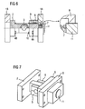
Fig. 6 und 7 ist eine gegenüber denFig. 1 bis 3 modifizierte Ausführungsform ersichtlich. - Die gelenkige Verbindung der beiden Wagenkästen 1A und 1B erfolgt über ein mehrteiliges Sphärolager 3. Dieses Sphärolager 3 ist einerseits mit seiner Außenhülse in einem feststehenden Innengelenk 2 angeordnet, das wiederum mittels Befestigungsmitteln 4B lösbar mit dem Wagenkasten 1B verbunden ist. Die Lagerung des Sphärolagerbolzens erfolgt mittels abnehmbarer Lagerschalen 6 in einem zum Außengelenk gehörenden Druckstück 5. Dieses Druckstück 5 ist in
Fig. 4 dargestellt. Die Übertragung von Druckkräften in Längsrichtung erfolgt dabei formschlüssig über ein beliebiges Kraftübertragungsglied 7 (hier beispielhaft als Schraubenfeder dargestellt) direkt auf den in seinem hinteren Teil topfförmig ausgebildeten Flansch 8 und von dort in den Wagenkasten 1A, an dem der Flansch 8 durch Befestigungsmittel 4A lösbar angebracht ist. Die Übertragung der Zugkräfte erfolgt über die Flächen 5.2 des Druckstücks 5 auf die Fläche 9.2 des inFig. 5 einzeln dargestellten Deckels 9 und von dort aus über Befestigungselemente 10 ebenfalls in den Flansch 8. Die Übertragung von Vertikalkräften und die Führung in Längsrichtung erfolgen über die am Druckstück 5 angeordneten Vorsprünge 5.1, die in den jeweiligen Nuten 9.1 des Deckels 9 angeordnet sind. Zur sicheren Übertragung der Kräfte vom Deckel 9 auf den Flansch 8 liegt der Deckel 9 mit seinen Flächen 9.3 an entsprechenden Gegenflächen des Flansches 8 an. - Bei der in
Fig. 6 und 7 gezeigten Variante der Erfindung ist zwischen dem Kraftübertragungsglied 7 und dem topfförmig ausgebildeten Flansch 8 ein Zwischenstück 11 als weiteres Bauteil angeordnet, das einen Toleranzausgleich in Längsrichtung ermöglicht, beispielsweise dadurch, dass das Zwischenstück 11 mittels Feingewinde im Flansch 8 angeordnet ist. Auch bei Anordnung dieses Zwischenstücks 11 wird der Vorteil der Erfindung gewahrt, wonach die Übertragung der Druckkräfte nicht über Gelenkbauteile erfolgt, die durch Befestigungsmittel miteinander verspannt sind. Das Feingewinde zwischen dem Flansch 8 und dem Zwischenstück 11 dient nicht dem Verspannen der Bauteile gegeneinander. Dieses Verspannen erfolgt vielmehr in der anhand derFig. 1 bis 3 beschriebenen Weise durch die Befestigungsmittel 10 zwischen dem Deckel 9 und dem Flansch 8. - In beiden Ausführungsbeispielen ist eine Verschieblichkeit nur in einer Gelenkhälfte vorgesehen, und zwar in dem das Druckstück 5, den topfförmigen Flansch 8 und den Deckel 9 aufweisenden Außengelenk. Alternativ besteht durchaus die Möglichkeit, das Innengelenk 2 als andere Gelenkhälfte im Sinne einer Verschieblichkeit auszuführen oder aber beide Gelenkhälften, also das Außengelenk und das Innengelenk 2, entsprechend dieser Verschieblichkeit zu gestalten.
Claims (6)
- Einrichtung zur gelenkigen Verbindung von auf einem gemeinsamen Drehgestell abgestützten Wagenkästen (1A, 1B) von Eisenbahnfahrzeugen, welche an jeweils einem Wagenkasten festlegbare Gelenkhälften aufweist, die eine Verdrehung um eine oder mehrere Achsen und/oder eine Verschiebung entlang einer oder mehrerer Achsen ermöglichen, wobei mindestens eine Gelenkhälfte derart ausgebildet ist, dass diese Gelenkhälfte unter bestimmten Betriebsumständen eine Verschieblichkeit der beiden Wagenkästen (1A, 1B) gegeneinander in Längsrichtung ermöglicht, dadurch gekennzeichnet, dass die Übertragung der Druckkräfte in Längsrichtung über die mindestens eine, für die Verschieblichkeit ausgebildete Gelenkhälfte ohne eine Beteiligung von miteinander durch Befestigungsmittel verbundenen Bauteilen erfolgt und diese Gelenkhälfte zur Übertragung der Druckkräfte in Längsrichtung ein Druckstück (5) aufweist, das innerhalb eines Deckels (9) in Längsrichtung geführt ist.
- Einrichtung nach Anspruch 1, dadurch gekennzeichnet, dass die Übertragung der Druckkräfte durch die mindestens eine, für die Verschieblichkeit ausgebildete Gelenkhälfte ausschließlich durch Formschluss erfolgt.
- Einrichtung nach Anspruch 1 oder 2, dadurch gekennzeichnet, dass im Kraftfluss der Druckkräfte in der mindestens einen, für die Verschieblichkeit ausgebildeten Gelenkhälfte ein Zwischenstück (11) zum Ausgleich von Maßtoleranzen in Längsrichtung angeordnet ist.
- Einrichtung nach einem der Ansprüche 1 bis 3, dadurch gekennzeichnet, dass die Übertragung der Zugkräfte, die Übertragung der Vertikalkräfte und die Führung der beweglichen Teile in Längsrichtung in der mindestens einen, für die Verschieblichkeit ausgebildeten Gelenkhälfte über den Deckel (9) erfolgt, der mit einem am Wagenkasten (1A) befestigten Flansch (8) durch Befestigungselemente (10) verbunden ist.
- Einrichtung nach einem der Ansprüche 1 bis 4, dadurch gekennzeichnet, dass eine Verschieblichkeit nur in einer der Gelenkhälften vorgesehen ist.
- Einrichtung nach einem der Ansprüche 1 bis 4, dadurch gekennzeichnet, dass eine Verschieblichkeit in beiden Gelenkhälften vorgesehen ist.
Applications Claiming Priority (1)
| Application Number | Priority Date | Filing Date | Title |
|---|---|---|---|
| DE102005023946A DE102005023946A1 (de) | 2005-05-20 | 2005-05-20 | Einrichtung zur gelenkigen Verbindung von Eisenbahnfahrzeugen |
Publications (2)
| Publication Number | Publication Date |
|---|---|
| EP1724176A1 EP1724176A1 (de) | 2006-11-22 |
| EP1724176B1 true EP1724176B1 (de) | 2009-05-06 |
Family
ID=36863876
Family Applications (1)
| Application Number | Title | Priority Date | Filing Date |
|---|---|---|---|
| EP06110906A Expired - Lifetime EP1724176B1 (de) | 2005-05-20 | 2006-03-09 | Einrichtung zur gelenkigen Verbindung von Eisenbahnfahrzeugen |
Country Status (4)
| Country | Link |
|---|---|
| EP (1) | EP1724176B1 (de) |
| AT (1) | ATE430678T1 (de) |
| DE (2) | DE102005023946A1 (de) |
| ES (1) | ES2325454T3 (de) |
Families Citing this family (2)
| Publication number | Priority date | Publication date | Assignee | Title |
|---|---|---|---|---|
| DE102009017041B4 (de) * | 2009-04-09 | 2014-11-20 | Sigmund Geggerle | Teilbares, zwei Wagenenden abstützendes Drehgestell für Schienenfahrzeuge |
| DE102017114376A1 (de) | 2017-06-28 | 2019-01-03 | Axtone S.A. | Gelenkanordnung für ein Drehgestell umfassend zumindest ein Deformationselement und ein Verfahren zur Energieumwandlung |
Family Cites Families (7)
| Publication number | Priority date | Publication date | Assignee | Title |
|---|---|---|---|---|
| BE757499A (fr) * | 1970-10-14 | 1971-03-16 | Auxiliaire Internationale De C | Dispositif de stabilisation de vehicules sur rails pourvus de l'attelage automatique central. |
| DD107878A1 (de) * | 1973-10-26 | 1974-08-20 | ||
| DE19838763C2 (de) | 1998-08-26 | 2002-01-03 | W Greifenhagen | Vorrichtung zum Tragen und Fahren von Ausrüstung |
| DE10021967A1 (de) * | 2000-05-05 | 2001-11-08 | Scharfenbergkupplung Gmbh & Co | Vorrichtung zur gelenkigen Verbindung von Wagenkästen eines mehrgliedrigen Schienenfahrzeuges |
| DK1312527T3 (da) | 2001-09-17 | 2003-09-29 | Voith Turbo Scharfenberg Gmbh | Leddelt sammenkobling |
| DE10153460A1 (de) | 2001-10-30 | 2003-05-22 | Voith Turbo Scharfenberg Gmbh | Kupplungsvorrichtung für die auf einem gemeinsamen Fahrwerk abgestützten Enden zweier gelenkig miteinander verbundenen, benachbarten Fahrzeugeinheiten eines schienengebundenen Gliederfahrzeuges |
| SE526057C2 (sv) * | 2003-09-10 | 2005-06-21 | Dellner Couplers Ab | Rälsbunden vagn jämte länkanordning för permanent hopkoppling av två i en dylik vagn ingående chassin |
-
2005
- 2005-05-20 DE DE102005023946A patent/DE102005023946A1/de not_active Withdrawn
-
2006
- 2006-03-09 DE DE502006003649T patent/DE502006003649D1/de not_active Expired - Lifetime
- 2006-03-09 EP EP06110906A patent/EP1724176B1/de not_active Expired - Lifetime
- 2006-03-09 AT AT06110906T patent/ATE430678T1/de active
- 2006-03-09 ES ES06110906T patent/ES2325454T3/es not_active Expired - Lifetime
Also Published As
| Publication number | Publication date |
|---|---|
| DE502006003649D1 (de) | 2009-06-18 |
| ES2325454T3 (es) | 2009-09-04 |
| EP1724176A1 (de) | 2006-11-22 |
| ATE430678T1 (de) | 2009-05-15 |
| DE102005023946A1 (de) | 2006-11-23 |
Similar Documents
| Publication | Publication Date | Title |
|---|---|---|
| EP2243680B1 (de) | Anlenkung zum gelenkigen Verbinden einer Kupplungsstange mit einem Wagenkasten | |
| DE102016104188B4 (de) | Vorrichtung zum Aktivieren von mindestens einer Funktionskomponente einer automatischen Mittelpufferkupplung | |
| EP3288814B1 (de) | Schienenfahrzeug mit einer anlenkung zum gelenkigen verbinden eines wagenkastenseitigen endbereiches einer kupplungsstange mit einem wagenkasten | |
| EP0567950A1 (de) | Schienenfahrzeug | |
| EP3686078A1 (de) | Schienenfahrzeug | |
| DE19543183A1 (de) | Lange Kupplung für Eisenbahnwagen | |
| EP1946988B1 (de) | Vorrichtung zur gelenkigen Anbindung einer Kupplungsstange an ein Fahrzeug | |
| EP2167362B1 (de) | Fahrzeug mit gelenkig verbundenen wagenkästen | |
| EP2562062B1 (de) | Abstützvorrichtung zum vertikalen Abstützen einer an einem Wagenkastenuntergestell eines spurgeführten Fahrzeuges angelenkten Kupplungsstange | |
| EP2598391B1 (de) | Mehrteiliges schienenfahrzeug mit wenigstens zwei, über ein doppelgelenk verbundenen wagenkästen | |
| EP3098133B1 (de) | Vorrichtung zum adaptieren eines kupplungskopfes einer mittelpufferkupplung der willison-bauart mit einer gelenkhälfte einer gelenkanordnung | |
| EP3837148A1 (de) | Gelenkanordnung zum gelenkigen verbinden von zwei benachbarten wagenkästen eines spurgeführten fahrzeuges | |
| DE10121266B4 (de) | Vorrichtung zur Führung eines Drehgestells | |
| EP1342637A1 (de) | Kuppelstange | |
| DE102004050369A1 (de) | Großräumiges Fahrzeug zur Personenbeförderung, insbesondere Schienenfahrzeug, mit gelenkig verbundenen Wagenkästen | |
| DE433463C (de) | Zug- und Stossvorrichtung | |
| EP3490869B1 (de) | Querweiches einfachgelenk mit angenäherter geradführung mittels deichsel | |
| EP1724176A1 (de) | Einrichtung zur gelenkigen Verbindung von Eisenbahnfahrzeugen | |
| EP1897777B1 (de) | Drehgestell | |
| EP1897776B1 (de) | Drehgestell | |
| EP3429899B1 (de) | Vorrichtung zur blockierung der torsionsbewegung zwischen zwei gekuppelten schienenfahrzeugen | |
| EP1763466B1 (de) | Kupplungsmuffenverbindung mit dreiteiliger übergangsabstützplatte | |
| EP2559605A2 (de) | Schienenfahrzeug mit einstufiger Federung | |
| DE102016219201A1 (de) | Kupplungsvorrichtung für auf einem gemeinsamen Fahrwerk abgestützte Wagenkästen eines Schienenfahrzeugs | |
| AT528290B1 (de) | Anlenkstange |
Legal Events
| Date | Code | Title | Description |
|---|---|---|---|
| PUAI | Public reference made under article 153(3) epc to a published international application that has entered the european phase |
Free format text: ORIGINAL CODE: 0009012 |
|
| AK | Designated contracting states |
Kind code of ref document: A1 Designated state(s): AT BE BG CH CY CZ DE DK EE ES FI FR GB GR HU IE IS IT LI LT LU LV MC NL PL PT RO SE SI SK TR |
|
| AX | Request for extension of the european patent |
Extension state: AL BA HR MK YU |
|
| 17P | Request for examination filed |
Effective date: 20070521 |
|
| 17Q | First examination report despatched |
Effective date: 20070621 |
|
| AKX | Designation fees paid |
Designated state(s): AT BE BG CH CY CZ DE DK EE ES FI FR GB GR HU IE IS IT LI LT LU LV MC NL PL PT RO SE SI SK TR |
|
| R17C | First examination report despatched (corrected) |
Effective date: 20070717 |
|
| GRAP | Despatch of communication of intention to grant a patent |
Free format text: ORIGINAL CODE: EPIDOSNIGR1 |
|
| GRAS | Grant fee paid |
Free format text: ORIGINAL CODE: EPIDOSNIGR3 |
|
| GRAA | (expected) grant |
Free format text: ORIGINAL CODE: 0009210 |
|
| AK | Designated contracting states |
Kind code of ref document: B1 Designated state(s): AT BE BG CH CY CZ DE DK EE ES FI FR GB GR HU IE IS IT LI LT LU LV MC NL PL PT RO SE SI SK TR |
|
| REG | Reference to a national code |
Ref country code: GB Ref legal event code: FG4D Free format text: NOT ENGLISH |
|
| REG | Reference to a national code |
Ref country code: CH Ref legal event code: EP Ref country code: CH Ref legal event code: NV Representative=s name: SIEMENS SCHWEIZ AG |
|
| REG | Reference to a national code |
Ref country code: IE Ref legal event code: FG4D |
|
| REF | Corresponds to: |
Ref document number: 502006003649 Country of ref document: DE Date of ref document: 20090618 Kind code of ref document: P |
|
| REG | Reference to a national code |
Ref country code: SE Ref legal event code: TRGR |
|
| REG | Reference to a national code |
Ref country code: ES Ref legal event code: FG2A Ref document number: 2325454 Country of ref document: ES Kind code of ref document: T3 |
|
| PG25 | Lapsed in a contracting state [announced via postgrant information from national office to epo] |
Ref country code: PT Free format text: LAPSE BECAUSE OF FAILURE TO SUBMIT A TRANSLATION OF THE DESCRIPTION OR TO PAY THE FEE WITHIN THE PRESCRIBED TIME-LIMIT Effective date: 20090906 Ref country code: FI Free format text: LAPSE BECAUSE OF FAILURE TO SUBMIT A TRANSLATION OF THE DESCRIPTION OR TO PAY THE FEE WITHIN THE PRESCRIBED TIME-LIMIT Effective date: 20090506 Ref country code: LT Free format text: LAPSE BECAUSE OF FAILURE TO SUBMIT A TRANSLATION OF THE DESCRIPTION OR TO PAY THE FEE WITHIN THE PRESCRIBED TIME-LIMIT Effective date: 20090506 |
|
| PG25 | Lapsed in a contracting state [announced via postgrant information from national office to epo] |
Ref country code: SI Free format text: LAPSE BECAUSE OF FAILURE TO SUBMIT A TRANSLATION OF THE DESCRIPTION OR TO PAY THE FEE WITHIN THE PRESCRIBED TIME-LIMIT Effective date: 20090506 Ref country code: PL Free format text: LAPSE BECAUSE OF FAILURE TO SUBMIT A TRANSLATION OF THE DESCRIPTION OR TO PAY THE FEE WITHIN THE PRESCRIBED TIME-LIMIT Effective date: 20090506 Ref country code: LV Free format text: LAPSE BECAUSE OF FAILURE TO SUBMIT A TRANSLATION OF THE DESCRIPTION OR TO PAY THE FEE WITHIN THE PRESCRIBED TIME-LIMIT Effective date: 20090506 Ref country code: IS Free format text: LAPSE BECAUSE OF FAILURE TO SUBMIT A TRANSLATION OF THE DESCRIPTION OR TO PAY THE FEE WITHIN THE PRESCRIBED TIME-LIMIT Effective date: 20090906 |
|
| REG | Reference to a national code |
Ref country code: IE Ref legal event code: FD4D |
|
| PG25 | Lapsed in a contracting state [announced via postgrant information from national office to epo] |
Ref country code: IE Free format text: LAPSE BECAUSE OF FAILURE TO SUBMIT A TRANSLATION OF THE DESCRIPTION OR TO PAY THE FEE WITHIN THE PRESCRIBED TIME-LIMIT Effective date: 20090506 Ref country code: DK Free format text: LAPSE BECAUSE OF FAILURE TO SUBMIT A TRANSLATION OF THE DESCRIPTION OR TO PAY THE FEE WITHIN THE PRESCRIBED TIME-LIMIT Effective date: 20090506 Ref country code: EE Free format text: LAPSE BECAUSE OF FAILURE TO SUBMIT A TRANSLATION OF THE DESCRIPTION OR TO PAY THE FEE WITHIN THE PRESCRIBED TIME-LIMIT Effective date: 20090506 Ref country code: RO Free format text: LAPSE BECAUSE OF FAILURE TO SUBMIT A TRANSLATION OF THE DESCRIPTION OR TO PAY THE FEE WITHIN THE PRESCRIBED TIME-LIMIT Effective date: 20090506 |
|
| PG25 | Lapsed in a contracting state [announced via postgrant information from national office to epo] |
Ref country code: SK Free format text: LAPSE BECAUSE OF FAILURE TO SUBMIT A TRANSLATION OF THE DESCRIPTION OR TO PAY THE FEE WITHIN THE PRESCRIBED TIME-LIMIT Effective date: 20090506 |
|
| PLBE | No opposition filed within time limit |
Free format text: ORIGINAL CODE: 0009261 |
|
| STAA | Information on the status of an ep patent application or granted ep patent |
Free format text: STATUS: NO OPPOSITION FILED WITHIN TIME LIMIT |
|
| PG25 | Lapsed in a contracting state [announced via postgrant information from national office to epo] |
Ref country code: BG Free format text: LAPSE BECAUSE OF FAILURE TO SUBMIT A TRANSLATION OF THE DESCRIPTION OR TO PAY THE FEE WITHIN THE PRESCRIBED TIME-LIMIT Effective date: 20090806 |
|
| 26N | No opposition filed |
Effective date: 20100209 |
|
| PGFP | Annual fee paid to national office [announced via postgrant information from national office to epo] |
Ref country code: CZ Payment date: 20100308 Year of fee payment: 5 |
|
| PGFP | Annual fee paid to national office [announced via postgrant information from national office to epo] |
Ref country code: NL Payment date: 20100303 Year of fee payment: 5 |
|
| PG25 | Lapsed in a contracting state [announced via postgrant information from national office to epo] |
Ref country code: MC Free format text: LAPSE BECAUSE OF NON-PAYMENT OF DUE FEES Effective date: 20100331 Ref country code: GR Free format text: LAPSE BECAUSE OF FAILURE TO SUBMIT A TRANSLATION OF THE DESCRIPTION OR TO PAY THE FEE WITHIN THE PRESCRIBED TIME-LIMIT Effective date: 20090807 |
|
| PGFP | Annual fee paid to national office [announced via postgrant information from national office to epo] |
Ref country code: SE Payment date: 20100309 Year of fee payment: 5 |
|
| PGFP | Annual fee paid to national office [announced via postgrant information from national office to epo] |
Ref country code: BE Payment date: 20110414 Year of fee payment: 6 |
|
| REG | Reference to a national code |
Ref country code: NL Ref legal event code: V1 Effective date: 20111001 |
|
| REG | Reference to a national code |
Ref country code: SE Ref legal event code: EUG |
|
| PG25 | Lapsed in a contracting state [announced via postgrant information from national office to epo] |
Ref country code: CZ Free format text: LAPSE BECAUSE OF NON-PAYMENT OF DUE FEES Effective date: 20110309 |
|
| PG25 | Lapsed in a contracting state [announced via postgrant information from national office to epo] |
Ref country code: DE Free format text: LAPSE BECAUSE OF NON-PAYMENT OF DUE FEES Effective date: 20111001 Ref country code: NL Free format text: LAPSE BECAUSE OF NON-PAYMENT OF DUE FEES Effective date: 20111001 |
|
| PG25 | Lapsed in a contracting state [announced via postgrant information from national office to epo] |
Ref country code: CY Free format text: LAPSE BECAUSE OF FAILURE TO SUBMIT A TRANSLATION OF THE DESCRIPTION OR TO PAY THE FEE WITHIN THE PRESCRIBED TIME-LIMIT Effective date: 20090506 |
|
| PG25 | Lapsed in a contracting state [announced via postgrant information from national office to epo] |
Ref country code: LU Free format text: LAPSE BECAUSE OF NON-PAYMENT OF DUE FEES Effective date: 20100309 Ref country code: HU Free format text: LAPSE BECAUSE OF FAILURE TO SUBMIT A TRANSLATION OF THE DESCRIPTION OR TO PAY THE FEE WITHIN THE PRESCRIBED TIME-LIMIT Effective date: 20091107 |
|
| BERE | Be: lapsed |
Owner name: SIEMENS A.G. Effective date: 20120331 |
|
| PG25 | Lapsed in a contracting state [announced via postgrant information from national office to epo] |
Ref country code: TR Free format text: LAPSE BECAUSE OF FAILURE TO SUBMIT A TRANSLATION OF THE DESCRIPTION OR TO PAY THE FEE WITHIN THE PRESCRIBED TIME-LIMIT Effective date: 20090506 |
|
| PG25 | Lapsed in a contracting state [announced via postgrant information from national office to epo] |
Ref country code: BE Free format text: LAPSE BECAUSE OF NON-PAYMENT OF DUE FEES Effective date: 20120331 |
|
| PGFP | Annual fee paid to national office [announced via postgrant information from national office to epo] |
Ref country code: AT Payment date: 20120207 Year of fee payment: 7 |
|
| PG25 | Lapsed in a contracting state [announced via postgrant information from national office to epo] |
Ref country code: SE Free format text: LAPSE BECAUSE OF NON-PAYMENT OF DUE FEES Effective date: 20110310 |
|
| REG | Reference to a national code |
Ref country code: AT Ref legal event code: MM01 Ref document number: 430678 Country of ref document: AT Kind code of ref document: T Effective date: 20130309 |
|
| PG25 | Lapsed in a contracting state [announced via postgrant information from national office to epo] |
Ref country code: AT Free format text: LAPSE BECAUSE OF NON-PAYMENT OF DUE FEES Effective date: 20130309 |
|
| PGFP | Annual fee paid to national office [announced via postgrant information from national office to epo] |
Ref country code: CH Payment date: 20140605 Year of fee payment: 9 |
|
| PGFP | Annual fee paid to national office [announced via postgrant information from national office to epo] |
Ref country code: IT Payment date: 20150328 Year of fee payment: 10 |
|
| PGFP | Annual fee paid to national office [announced via postgrant information from national office to epo] |
Ref country code: ES Payment date: 20150409 Year of fee payment: 10 |
|
| REG | Reference to a national code |
Ref country code: CH Ref legal event code: PL |
|
| PG25 | Lapsed in a contracting state [announced via postgrant information from national office to epo] |
Ref country code: CH Free format text: LAPSE BECAUSE OF NON-PAYMENT OF DUE FEES Effective date: 20150331 Ref country code: LI Free format text: LAPSE BECAUSE OF NON-PAYMENT OF DUE FEES Effective date: 20150331 |
|
| REG | Reference to a national code |
Ref country code: FR Ref legal event code: PLFP Year of fee payment: 11 |
|
| PG25 | Lapsed in a contracting state [announced via postgrant information from national office to epo] |
Ref country code: IT Free format text: LAPSE BECAUSE OF NON-PAYMENT OF DUE FEES Effective date: 20160309 |
|
| REG | Reference to a national code |
Ref country code: FR Ref legal event code: PLFP Year of fee payment: 12 |
|
| PGFP | Annual fee paid to national office [announced via postgrant information from national office to epo] |
Ref country code: DE Payment date: 20170519 Year of fee payment: 12 |
|
| REG | Reference to a national code |
Ref country code: FR Ref legal event code: PLFP Year of fee payment: 13 |
|
| PGFP | Annual fee paid to national office [announced via postgrant information from national office to epo] |
Ref country code: GB Payment date: 20180312 Year of fee payment: 13 |
|
| PG25 | Lapsed in a contracting state [announced via postgrant information from national office to epo] |
Ref country code: ES Free format text: LAPSE BECAUSE OF NON-PAYMENT OF DUE FEES Effective date: 20160310 |
|
| PGFP | Annual fee paid to national office [announced via postgrant information from national office to epo] |
Ref country code: FR Payment date: 20180312 Year of fee payment: 13 |
|
| REG | Reference to a national code |
Ref country code: DE Ref legal event code: R119 Ref document number: 502006003649 Country of ref document: DE |
|
| REG | Reference to a national code |
Ref country code: ES Ref legal event code: FD2A Effective date: 20181207 |
|
| GBPC | Gb: european patent ceased through non-payment of renewal fee |
Effective date: 20190309 |
|
| PG25 | Lapsed in a contracting state [announced via postgrant information from national office to epo] |
Ref country code: GB Free format text: LAPSE BECAUSE OF NON-PAYMENT OF DUE FEES Effective date: 20190309 |
|
| PG25 | Lapsed in a contracting state [announced via postgrant information from national office to epo] |
Ref country code: FR Free format text: LAPSE BECAUSE OF NON-PAYMENT OF DUE FEES Effective date: 20190331 |
|
| PG25 | Lapsed in a contracting state [announced via postgrant information from national office to epo] |
Ref country code: DE Free format text: LAPSE BECAUSE OF NON-PAYMENT OF DUE FEES Effective date: 20181002 |