EP1714798A1 - Leichtlegierungsrad - Google Patents
Leichtlegierungsrad Download PDFInfo
- Publication number
- EP1714798A1 EP1714798A1 EP04787915A EP04787915A EP1714798A1 EP 1714798 A1 EP1714798 A1 EP 1714798A1 EP 04787915 A EP04787915 A EP 04787915A EP 04787915 A EP04787915 A EP 04787915A EP 1714798 A1 EP1714798 A1 EP 1714798A1
- Authority
- EP
- European Patent Office
- Prior art keywords
- rim
- wall
- tubular
- rim part
- wheel
- Prior art date
- Legal status (The legal status is an assumption and is not a legal conclusion. Google has not performed a legal analysis and makes no representation as to the accuracy of the status listed.)
- Granted
Links
Images


Classifications
-
- B—PERFORMING OPERATIONS; TRANSPORTING
- B60—VEHICLES IN GENERAL
- B60B—VEHICLE WHEELS; CASTORS; AXLES FOR WHEELS OR CASTORS; INCREASING WHEEL ADHESION
- B60B21/00—Rims
- B60B21/02—Rims characterised by transverse section
- B60B21/025—Rims characterised by transverse section the transverse section being hollow
-
- B—PERFORMING OPERATIONS; TRANSPORTING
- B60—VEHICLES IN GENERAL
- B60B—VEHICLE WHEELS; CASTORS; AXLES FOR WHEELS OR CASTORS; INCREASING WHEEL ADHESION
- B60B21/00—Rims
- B60B21/02—Rims characterised by transverse section
- B60B21/028—Rims characterised by transverse section the shape of hump
-
- B—PERFORMING OPERATIONS; TRANSPORTING
- B60—VEHICLES IN GENERAL
- B60B—VEHICLE WHEELS; CASTORS; AXLES FOR WHEELS OR CASTORS; INCREASING WHEEL ADHESION
- B60B21/00—Rims
- B60B21/10—Rims characterised by the form of tyre-seat or flange, e.g. corrugated
- B60B21/102—Rims characterised by the form of tyre-seat or flange, e.g. corrugated the shape of bead seats
-
- B—PERFORMING OPERATIONS; TRANSPORTING
- B60—VEHICLES IN GENERAL
- B60B—VEHICLE WHEELS; CASTORS; AXLES FOR WHEELS OR CASTORS; INCREASING WHEEL ADHESION
- B60B21/00—Rims
- B60B21/10—Rims characterised by the form of tyre-seat or flange, e.g. corrugated
- B60B21/104—Rims characterised by the form of tyre-seat or flange, e.g. corrugated the shape of flanges
Definitions
- This invention relates to a wheel formed of lightweight metal for two-wheeled vehicles and motorcycles as well as automobiles having at least four wheels; in which cavity is formed and rigidity is enhanced in rim part so as to enlarge width of outer rim and avoid weight increase due to such enlarging, in order to achieve broad extent of flexibility on ornamental designing of the outer rim part of the wheel, such as "soft rim” that is trendy in recent years.
- the light alloy wheel is made from aluminum or magnesium and is light-weight and easy to be worked.
- the light alloy wheels excellent in ornamental appearance are provided; and mounting ratio or share of the light alloy wheels is increased to an extent that such light alloy wheels are mounted on vehicles at their assembly lines.
- Exterior contour of the outer rim is restricted by ETRTO (European Tire and Rim Technical Organization) standard or by JATMA (Japan Automobile Tire Manufactures Association) standard; in regard to contour of tire-mounting side of the outer rim, such as contours of a bead seat, a hump, a slope extending between the hump and a rim well, as well as of inner face of a rim flange.
- outer circumferential part of the rim Due to contour-wise restrictions by the standards, even though there are some contour-wise deviations, outer circumferential part of the rim has to have a large width when to adopt the so-called soft rim or the like, in which exterior side of the rim is formed to have gentle curvature. Thus, areal size of the cross section of the outer rim become large and thereby causing disadvantage of weight increase of the wheel.
- Inclination of the slope extending between the hump to the rim well, in the four-wheel automobile is stipulated to be 20 degree or more in respect of a plane perpendicular to the rotational axis in the ETRTO standard, and is stipulated to be 20 ⁇ 5 degree in the JATMA standard.
- Dimension of the slope in regard to "height" or dimension in wheel-radial direction between the bead seat and the rim well is stipulated to be 17.3mm or more in the ETRTO standard, and is stipulated to be 17.0mm or more in the JATMA standard.
- the dimension of the slope tends to become large, and thereby forming the wheel that has small offset dimension.
- distinctive fashionability is achieved as a disc face is arranged at depth-wise inward of the wheel.
- strength of the rim is deteriorated and weight of the wheel is increased because wall thickness is increased to increase weight of the wheel.
- Such wheels are taken up to be favorable in aftermarket or spare wheel market, but are not adopted by automobile makers.
- Reason for this is as follows; rigidity of the wheel is decreased and construction of the braking mechanism is enlarged, so that offset dimension is enlarged and the disc has to be arranged in vicinity of the outer rim flange.
- the inclination of the slope makes a large difference in rigidity of the rim, and thus it is desirable to set the inclination in view of such difference.
- Wheels for the two-wheeled vehicles are also specified in the ETRTO and JATMA standards: the inclination of the slope extending from the rim well to the hump is around 22 degree with tolerance of 5 degree; the height or radial dimension of the hump is 12.5-13mm; and the inclination of the bead seat is 5 ⁇ 1 degree.
- the wheel for the two-wheeled vehicles is almost homothetic to that for the four-wheeled vehicles except that inner and outer rims are indistinctive with each other and have same contour.
- the invention-wise light alloy wheel comprises an outer rim having a tubular rim part that is consisting of: a bead seat (B); a hump (H); a slope wall (S); an ornamental wall (D); and a cavity defined by these four walls; and wherein, when assuming a solid rim part that is consisting of the bead seat, the hump and the slope wall and has a typical standardized shaping construction in respect of inclination, dimensions and wall thicknesses, and in conformity mainly with design specification of a tire;
- shaping of the outer rim is modified to have the cavity so that ornamental design on exterior view of the outer rim is freely set irrespective of contour on tire-mounting face of the outer rim, which is more or less restricted by shaping or dimension of the wheel based on the ETRTO or JATMA standard.
- exterior face of the rim may be provided with any of various ornamental design in a manner to widen a range of adoptable variations of ornamental design of wheel, which match up ornamental design of the body of the automobile.
- the bead seat, the hump and the slope wall, which forms a rim wall of the light alloy wheel, are integrally formed with additional rim wall, as to form a cavity.
- Fig. 1(a) is a sectional view showing an outer rim 1 that is manufactured by conventional forging technique; a rim wall 1a, which is designated by hatching, is consisting of a bead seat B, a hump H and a slope wall S; and the outer rim 1 is formed of the rim wall 1 a and a flange wall F that forms an outer flange 2.
- the outer flange 2 is required to be shaped to have a thickness enough for bearing stress in axial direction, while areal size of the outer flange 2 is rather small or insufficient to form main part of the ornamental design and thus, the outer flange 2 makes an ornamental exterior face appendant to the ornamental wall D.
- a rim well 3 that is continuous with inner rim is formed to have a radius from the axis in an extent to avoid contact with braking device. Height or radius from the axis, of the bead seat raised from the rim well 3 is determined as to form a recess required for deeply placing of a tire on course of mounting the tire. Walls of the rim well and the bead seat have thickness of about 3-8mm while the thickness varies depending to manufacturing method adopted among forging, casting and die casting and the like.
- outer face of a rim wall 1a consisting of the bead seat B, the hump H and the slope wall S is shaped as similar with tire-mounting face of the rim wall and would realize ornamental appearance of the outer rim 1.
- an additional rim wall 4 as an ornamental wall D is integrally formed as to bridge between the flange wall and the rim well, so that outer face of the ornamental wall makes exterior face realizing the ornamental appearance and may be modified to take various contours.
- Fig. 1(b) is a cross-sectional contour of the outer rim 1' of a wheel that is manufactured by casting technique and has inner diameter same with that of the above-described wheel. Due to difference in strength of the metal, a rim wall 1b is thick-walled and additional rim wall 4b as an ornamental wall D is formed integrally with the main rim wall 1 b. Thus, a cavity 5 or 5b is formed by providing the additional rim wall 4 or 4b respectively.
- wall thickness of the additional rim wall 4 shown in Fig. 1(a) may be variously set, excess thickening is not desirable because cross-sectional area of solid part of the tubular rim part increases with the increase of the wall thickness.
- the rim wall 1 a and the additional rim wall 4 forms a cavity 5 as to form a tubular rim part that improves resistibility against deformation of the wheel by an external force.
- the resistibility may be calculated as geometrical moment of inertia, while the resistibility may also be called as rigidity.
- a cross section of tubular rim part having the tubular shaping construction 2-2 in the Fig. 2 is substantially triangular, and has the additional rim wall 4 integrally formed with the rim wall 1a.
- the coordinate axis "x" is taken as a direction along diameter of the wheel; and the coordinate axis "y” is taken as a width direction of the rim.
- the ornamental wall D, as the additional rim wall, of tubular shaping constructions 2-3 to 2-7 is formed of; a pair of flat faces having an angle between them, and/or a smoothly curved face. Percentage values for each of the tubular shaping construction are on basis of amounts for the conventional shaping 2-1.
- tubular shaping constructions 2-3 and 2-5 are preferable also in view of ornamental appearance; and when to prescribe the geometrical moment of inertia about the x axis and y axis in a well-balanced manner, the tubular shaping construction 2-5 is advantageous in which the geometrical moment of inertia about the y axis is increased.
- casting technique is preferred in view of production cost and process steps, while the forging technique is also adoptable.
- the additional rim wall 4 is added for forming the cavity onto the rim wall 1a that is shaped as a result of pursuing a light-weight structure.
- decreasing of weight is not achievable, while rigidity of the rim is increased due to increase of the cross-sectional area.
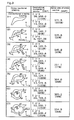
- a basic shaping as shown in Fig. 3.
- ratios of the aerial size of the cross section and the geometrical moments of inertia with regard to the basic shaping 3-1 are calculated and shown in the Fig. 3.
- the casted wheel is inferior to the forged wheel in view of compression and tensile strengths of the light alloy material.
- thickness of rim wall 1 a is designed to be large.
- cross sectional area of the rim wall 1a becomes about 1.5 time of that of the forged one.
- a tubular shaping construction 3-2 on Fig. 3 the additional rim wall 4b (please see Fig. 1(b)) is integrally formed to form a cavity 5b. Shaping of the additional rim 4b is modified to give tubular shaping construction 3-3 to 3-7 as shown in the figure.
- Tubular shaping constructions 3-3 and 3-5 give cross-sectional areas no more than that of the typical conventional shaping 3-1; and have well-balanced geometrical moments of inertia about the x axis and the y axis.
- Tubular shaping construction 3-4 gives low geometrical moment of inertia although giving a light weight construction, compared with the tubular shaping construction 3-2. Hence, the additional rim 4b is preferred to protrude outwardly.
- Tubular shaping construction 3-5 is constructed such that flat walls are added onto the smoothly curved walls of the tubular shaping construction 3-3, and has a large extent of variability and best balancing. Thus, further investigations and modifications are made onto the tubular shaping construction 3-5.
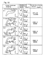
- the bead seat B, the hump H, the slope wall S and the additional rim wall 4b, which consist the tubular rim part having the cavity, are varied in shape and wall thickness "t".
- the geometrical moments of inertia are calculated and shown in Figs. 4 and 5.
- Increase of thickness of the walls certainly causes increase in cross-sectional area and the geometrical moments of inertia. Because outside contour of the tubular rim part is kept constant at this varying, cross-sectional areal size of the cavity varies.
- Fig. 7 is a table showing the aerial size of the cross section and the geometrical moment of inertia, which are obtained by varying wall thicknesses of the bead seat B, the slope wall S and the additional rim wall 4b so as to give the aerial size in a range of 70-100% of the typical conventional shaping 3-1 for casting technique.
- tubular shaping constructions 4-4 and 4-5 are preferred.
- the tubular shaping constructions 4-2 to 4-5 have well-balanced geometrical moments of inertia about the x axis and the y axis. It is known from these results that thicknesses St, Bt and Dt of the slope wall, the bead seat and the ornamental wall may be varied.
- wall thickness may be gradually or smoothly varied from one portion to another, according to running condition, time-wise change of production specification of tires, distribution of weight of automobile, fore-rear-wise distribution of driving force in 4-wheel drive vehicles, and time-wise change of seat suspension performance.
- Fig. 8 is a graph showing plots of results already shown in Figs. 4-6, aiming for obtaining optimum wall thickness "t".
- the per-sectional-area geometrical moments of inertia about the x axis and the y axis decrease with increase of wall thickness "t"; and the geometrical moments of inertia increase with increase of wall thickness "t".
- a horizontal line 10 is drawn to a level of the geometrical moments of inertia at 100% of that of the typical conventional shaping construction 3-1; a vertical line 12 is drawn at an intersection point P between the horizontal line 10 and a curve 11 of the geometrical moment of inertia about x axis; and a vertical line 13 is drawn at a point of 3.75mm thickness where the aerial size becomes 100% of that of the typical conventional shaping construction.
- Optimum area is designated by a hatched area in the figure, which is surrounded by the two vertical lines 11 and 12 and four curves, which are the curve 13 of the geometrical moment of inertia about x axis, the curve 14 of the geometrical moment of inertia about y axis, a curve 15 for the per-sectional-area geometrical moments of inertia about the x axis and a curve 16 for the per-sectional-area geometrical moments of inertia about the x axis.
- optimum range of wall thickness is 2.3 mm to 4 mm; and 3-4mm is most preferable when both of workability and practical application are taken into consideration.
- Fig. 7 shows, in a tabular form, the aerial size of the cross section, the geometrical moments of inertia and their ratio when thicknesses Bt, St and Dt of the bead seat, the slope wall and the ornamental wall D are set at thought-to-be preferred values.
- Fig. 9 is a graph plotting the results on the Fig. 7. Hatched area on the Fig. 9 represents considerably limited conditions in respect of shaping construction; the aerial size of the cross section is no more than 100% and the geometrical moments of inertia are no less than 100%.
- a cavity is formed by the additional rim wall 4b as shown in Fig. 1(b).
- a cavity is formed by the additional rim wall 4b as shown in Fig. 1(b).
- thicknesses Bt, St and Dt of the bead seat, the slope wall and the ornamental wall D may be portion-to-portion wise varied as to improve the geometrical moments of inertia, in a scope of the invention.
- a portion having an enlarged thickness may be provided to any of the wall elements forming the tubular construction, so as to facilitate flow of molten metal during the casting process.
- the results of Fig. 10 is useful when to take such construction and useful for suppressing the cross section to be no more than 100% of that of the typical conventional shaping construction.
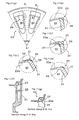
- Fig. 11 (a) in a partial elevation view showing a wheel 20 in which hollow spokes are joined with the rim having a cavity.
- Figs. 11 (f) and 11 (g) are cross-sectional views respectively along A-A' line and B-B' line in Fig. 11 (a).
- Fig. 11(f) shows a vertical cross section along a center line of the spoke 21, whose cavity 22 is communicated with cavity 24 of the rim.
- Fig. 11 (g) shows a vertical cross section of rim part 23 having the cavity.
- a dashed-line circle 29 in Fig. 11 (a) and shown in enlarged sectional views of Figs. 11 (b)-(e).
- junctions 25 will have a simple structure when the walls are joined to form nearly right-angled corners; nevertheless, such junctures will lead to stress concentration and cracks. Hence, preferably, augmentation is made to hatched area 26 in the Fig. 11 (c) in a manner that thickness is gradually enlarged.
- the augmentation will increase wall thickness of the spoke 21, the augmentation has to make a curved face longer at along the rim than that at along the spoke, as indicated by a dashed line 27.
- core molds for removing the hatched areas 28 are prepared as shown in Fig. 11 (b), or the trim-wise rounding is made by cutting.
- Fig. 11 (d) shows a construction in which walls of the spokes 21 are connected with the rim as to be inclined to the rim wall. In this way, angle between the walls at the junction 25 becomes small.
- the augmentation 31 is made in a manner to form a curved face with small curvature by eliminating corner edges and to be extended onto the rim wall 12a for its reinforcing, as indicated by a hatched area 26. On end of the extension of the augmentation, a concave portion 32 is formed.
- 11 (e) shows a construction in which the augmentation 31 is formed at junction between the rim's cavity and the spoke's cavity; and an undulation 33 is formed on the opening 30 and at along surface of the spokes 21 as to reinforce the wheel.
- the junction acts as a shock absorber by forming portions having large aerial size of cross section where stress-applying direction varies.
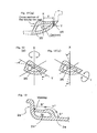
- Fig. 13 shows a construction in which the tubular rim construction as explained above is employed for inner rim.
- a bead seat B', a hump H', a slope wall S' and outer rim flange 2a' may be formed as same as above.
- the ornamental wall D is not viewable when the wheels are mounted on a vehicle and thus, an ornamental appeal is not required to the wall.
- a wall corresponding to the ornamental wall D is formed as an extension of the rim well 3a.
- rigidity of the wheel is increased and thus, wall thickness at the rim well 3a may be made to be smaller as to decrease weight of the wheel as a whole.
- Fig. 14 exemplarily illustrates one of the techniques.
- Fig. 14(a) shows a process step for forming the tubular rim construction and shows a rim 36a directly after the casting.
- Outer rim flange 2a, rim well 3a and part of the tubular construction are formed by the casting, simultaneously with a flange 37.
- the flange 37 is reclined to a position indicated by dashed lines, by pressing a roller tool of spinning machine.
- end of the flange 37 is welded onto a portion that is to comprise the tubular construction.
- Fig. 14(a) shows a process step for forming the tubular rim construction and shows a rim 36a directly after the casting.
- Outer rim flange 2a, rim well 3a and part of the tubular construction are formed by the casting, simultaneously with a flange 37.
- the flange 37 is reclined to a position indicated by dashed lines, by pressing a roller tool of spinning machine.
- FIG. 14(b) shows a completed rim 36 comprised of the tubular rim part 39, which is obtained after cutting on a side face of the flange 37 as to form the slope wall S, the hump H and the bead seat B, which define a cavity 38.
- a rib may be formed on inner face on the cavity 42, at a time freely designing the ornamental wall.
- Fig. 15 exemplarily shows such a construction.
- a rib 43 is formed annularly on cavity-side face of a wall of the tubular rim part, which wall is integrally connected with the spokes, in order to increase rigidity of the tubular construction.
- the rib may be simultaneously formed at the casting by making direction of projecting the rib agree with direction of removing from a mold tool.
- the annular rib may also be attached by welding after the casting; and in such case, the rib may be provided on any position at inside of the cavity in ways to improve the geometrical moments of inertia.
- the rim having a cavity and light-weight construction as well as excellent rigidity is obtained.
- the rim may be connected with hollow spokes so that cavities in the spokes are communicated with the cavity in the rim.
- the rim may also be connected with solid or be connected by screws with the rim, when for two-piece wheel for example. In any of such connecting manners, wheels with improved ornamental appeal are obtained due to the rims having the cavities as to further improve quality of the wheel.
- liquid metal forging, die casting or any other technique may be employed for producing a wheel or semi-finished wheel, as far as the technique employs a process for pouring heat-wise molten light metal into a mold and then cooling the metal in the mold.
- Reference numerals or marks 1 outer rim obtained by forging technique; 1' outer rim obtained by casting technique; 1 a a rim wall by the forging technique; 1b a rim wall by the casting technique; 2 outer rim; 3 rim well; 4 a rim wall; 5 a cavity by the forging technique; 5' a cavity by the casting technique; 20 a wheel having cavities; 21 a spoke; 23 a rim; 25 a joint; 30 an opening; 31 augmentation; 33 undulation; 37 a flange; 38 a cavity; and 43 a rib.
Landscapes
- Engineering & Computer Science (AREA)
- Mechanical Engineering (AREA)
- Molds, Cores, And Manufacturing Methods Thereof (AREA)
- Tires In General (AREA)
- Forging (AREA)
Applications Claiming Priority (2)
| Application Number | Priority Date | Filing Date | Title |
|---|---|---|---|
| JP2004027360 | 2004-02-03 | ||
| PCT/JP2004/013732 WO2005075220A1 (ja) | 2004-02-03 | 2004-09-21 | 軽合金製ホイール |
Publications (3)
| Publication Number | Publication Date |
|---|---|
| EP1714798A1 true EP1714798A1 (de) | 2006-10-25 |
| EP1714798A4 EP1714798A4 (de) | 2007-04-11 |
| EP1714798B1 EP1714798B1 (de) | 2012-09-12 |
Family
ID=34835890
Family Applications (1)
| Application Number | Title | Priority Date | Filing Date |
|---|---|---|---|
| EP04787915A Expired - Fee Related EP1714798B1 (de) | 2004-02-03 | 2004-09-21 | Leichtlegierungsrad |
Country Status (5)
| Country | Link |
|---|---|
| US (1) | US20080277996A1 (de) |
| EP (1) | EP1714798B1 (de) |
| JP (1) | JP4880305B2 (de) |
| CN (1) | CN1914051A (de) |
| WO (1) | WO2005075220A1 (de) |
Cited By (3)
| Publication number | Priority date | Publication date | Assignee | Title |
|---|---|---|---|---|
| EP2033809A1 (de) * | 2007-09-07 | 2009-03-11 | Kunshan Vuelta Wheel Co. Ltd. | Motorradfelge und Verfahren zu ihrer Herstellung |
| EP1986871A4 (de) * | 2005-08-30 | 2010-06-09 | Wilderness Trail Bikes Licensi | Fahrradradfelge |
| DE102013212120A1 (de) * | 2013-06-25 | 2015-01-08 | Bayerische Motoren Werke Aktiengesellschaft | Felge eines Kraftfahrzeug-Rades sowie Herstellverfahren hierfür |
Families Citing this family (12)
| Publication number | Priority date | Publication date | Assignee | Title |
|---|---|---|---|---|
| DE102004028841A1 (de) * | 2004-06-16 | 2006-01-19 | Bbs Motorsport & Engineering Gmbh | Leichtmetallrad |
| AT9907U1 (de) * | 2007-03-01 | 2008-05-15 | Austria Alu Guss Ges M B H | Gussrad sowie gussform zur herstellung eines gussrads |
| US20100096910A1 (en) * | 2008-10-21 | 2010-04-22 | Topy America, Inc. | High Rigidity Wheel Rim |
| JP5463162B2 (ja) * | 2010-02-24 | 2014-04-09 | 中央精機株式会社 | 車両用ホイールの製造方法 |
| CN102107582B (zh) * | 2011-01-20 | 2012-10-24 | 中北大学 | 一种重型车辆用铝合金车轮 |
| FR3015360B1 (fr) * | 2013-12-20 | 2016-01-01 | Michelin & Cie | Jante souple a crochets flottants |
| FR3015359B1 (fr) * | 2013-12-20 | 2016-01-01 | Michelin & Cie | Jante souple a crochets flottants |
| WO2015135155A1 (zh) * | 2014-03-12 | 2015-09-17 | 成都优阳机电产品设计有限公司 | 一种轮胎钢圈结构及轮胎 |
| CN104527324A (zh) * | 2014-12-04 | 2015-04-22 | 中信戴卡股份有限公司 | 一种改进的j型车轮轮辋 |
| WO2017159830A1 (ja) * | 2016-03-16 | 2017-09-21 | 本田技研工業株式会社 | 車両用ホイール |
| FR3082144B1 (fr) * | 2018-06-12 | 2021-12-31 | Renault Sas | Jante pour roue de vehicule |
| CN111559199B (zh) * | 2020-05-22 | 2022-03-15 | 福建申利卡铝业发展有限公司 | 一种刹车性能佳的新型车轮毂 |
Citations (2)
| Publication number | Priority date | Publication date | Assignee | Title |
|---|---|---|---|---|
| JPS6012314A (ja) * | 1983-06-30 | 1985-01-22 | Yamaha Motor Co Ltd | 車輪 |
| WO2001017799A1 (de) * | 1999-09-08 | 2001-03-15 | Bbs Motorsport & Engineering Gmbh | Leichtmetallrad |
Family Cites Families (17)
| Publication number | Priority date | Publication date | Assignee | Title |
|---|---|---|---|---|
| JPS5967305U (ja) * | 1982-10-29 | 1984-05-07 | 株式会社高砂製作所 | 軽合金製車輪リム |
| US5575539A (en) * | 1991-11-23 | 1996-11-19 | Dr. Ing. H.C.F. Porsche Ag | Wheel rim for a motor vehicle and process for making same |
| EP0547313B1 (de) * | 1991-11-23 | 1995-12-20 | Dr.Ing.h.c. F. Porsche Aktiengesellschaft | Felge und ein Verfahren zum Herstellen der Felge |
| US5538329A (en) * | 1991-11-23 | 1996-07-23 | Dr. Ing. H.C.F. Porsche Ag | Wheel for a motor vehicle and method of making same |
| DE4430489C1 (de) * | 1994-08-27 | 1995-10-26 | Porsche Ag | Rad |
| EP0698508A3 (de) * | 1994-08-27 | 1997-04-09 | Porsche Ag | Rad für ein Kraftfahrzeug |
| DE4430488A1 (de) * | 1994-08-27 | 1996-02-29 | Porsche Ag | Rad für ein Kraftfahrzeug |
| DE59603215D1 (de) * | 1995-10-11 | 1999-11-04 | Porsche Ag | Rad für ein Kraftfahrzeug |
| NO954273D0 (no) * | 1995-10-26 | 1995-10-26 | Norsk Hydro As | Hjulfelg |
| AU711230B2 (en) * | 1996-06-25 | 1999-10-07 | Dr. Ing H.C.F. Porsche Aktiengesellschaft | Wheel for a motor vehicle |
| DE19754959C2 (de) * | 1997-12-11 | 2001-05-17 | Porsche Ag | Rad für ein Kraftfahrzeug mit Hohlspeichen |
| JP2000108602A (ja) * | 1998-10-05 | 2000-04-18 | Daido Kogyo Co Ltd | 軽合金製車輪リム |
| JP2000142007A (ja) * | 1998-11-17 | 2000-05-23 | Topy Ind Ltd | 軽量化アルミホイールおよびその製造方法 |
| WO2000076785A1 (de) * | 1999-06-11 | 2000-12-21 | Dr. Ing. H.C. F. Porsche Aktiengesellschaft | Rad für ein kraftfahrzeug |
| DE19957255C2 (de) * | 1999-11-27 | 2001-10-31 | Bbs Motorsport & Eng Gmbh | Rad |
| AT4936U1 (de) * | 2000-10-06 | 2002-01-25 | Austria Alu Guss Ges M B H | Rad-gussfelge |
| BR0203723A (pt) * | 2002-09-12 | 2004-05-25 | Meritor Do Brasil Ltda | Roda e disco de roda |
-
2004
- 2004-09-21 US US10/588,355 patent/US20080277996A1/en not_active Abandoned
- 2004-09-21 WO PCT/JP2004/013732 patent/WO2005075220A1/ja active Application Filing
- 2004-09-21 JP JP2005517616A patent/JP4880305B2/ja not_active Expired - Fee Related
- 2004-09-21 CN CNA2004800413314A patent/CN1914051A/zh active Pending
- 2004-09-21 EP EP04787915A patent/EP1714798B1/de not_active Expired - Fee Related
Patent Citations (2)
| Publication number | Priority date | Publication date | Assignee | Title |
|---|---|---|---|---|
| JPS6012314A (ja) * | 1983-06-30 | 1985-01-22 | Yamaha Motor Co Ltd | 車輪 |
| WO2001017799A1 (de) * | 1999-09-08 | 2001-03-15 | Bbs Motorsport & Engineering Gmbh | Leichtmetallrad |
Non-Patent Citations (1)
| Title |
|---|
| See also references of WO2005075220A1 * |
Cited By (3)
| Publication number | Priority date | Publication date | Assignee | Title |
|---|---|---|---|---|
| EP1986871A4 (de) * | 2005-08-30 | 2010-06-09 | Wilderness Trail Bikes Licensi | Fahrradradfelge |
| EP2033809A1 (de) * | 2007-09-07 | 2009-03-11 | Kunshan Vuelta Wheel Co. Ltd. | Motorradfelge und Verfahren zu ihrer Herstellung |
| DE102013212120A1 (de) * | 2013-06-25 | 2015-01-08 | Bayerische Motoren Werke Aktiengesellschaft | Felge eines Kraftfahrzeug-Rades sowie Herstellverfahren hierfür |
Also Published As
| Publication number | Publication date |
|---|---|
| WO2005075220A1 (ja) | 2005-08-18 |
| EP1714798A4 (de) | 2007-04-11 |
| JP4880305B2 (ja) | 2012-02-22 |
| JPWO2005075220A1 (ja) | 2008-04-24 |
| US20080277996A1 (en) | 2008-11-13 |
| EP1714798B1 (de) | 2012-09-12 |
| CN1914051A (zh) | 2007-02-14 |
Similar Documents
| Publication | Publication Date | Title |
|---|---|---|
| EP1714798B1 (de) | Leichtlegierungsrad | |
| EP3172059B1 (de) | Gegossenes aluminiumrad | |
| US8814187B2 (en) | Transverse link, and method for producing a transverse link | |
| US8800148B2 (en) | Method of manufacturing an automotive wheel | |
| JPH09309479A (ja) | テーパー付角パイプ部材を使用した自動2輪車のリヤスイングアーム及びこの車体用テーパー付角パイプ部材の製法 | |
| CN102905911B (zh) | 汽车用车轮 | |
| EP4052922B1 (de) | Gegossenes rad für ein grätschsitzfahrzeug und verfahren zur herstellung davon | |
| JP4827507B2 (ja) | アクスルハウジング | |
| TW201819210A (zh) | 用於車輪的輻條和用於製造該輻條的方法 | |
| JP5091829B2 (ja) | 車両用ホイール | |
| JP3900434B2 (ja) | 車両用ホイール | |
| JP3778475B2 (ja) | テーパー付角パイプ部材の製法 | |
| KR101406498B1 (ko) | 자동차용 휠 제조방법 및 이에 의해 제조된 자동차용 휠 | |
| JP2005001549A (ja) | 車両用ホイール | |
| JP4068849B2 (ja) | オフセット部を有する自動車用サスペンション部品 | |
| CN212194915U (zh) | 轮圈和铝辐条焊接轮毂 | |
| JP4622337B2 (ja) | 自動車用ロードホイール | |
| KR20090064684A (ko) | 알루미늄 휠과 그의 제조방법 | |
| WO2020066446A1 (ja) | 二輪自動車用軽合金製リム | |
| CN111301055A (zh) | 轮圈和铝辐条焊接轮毂 | |
| JP3781271B2 (ja) | 車両用軽合金製ホイール | |
| US20050034305A1 (en) | Method of producing a light alloy wheel rim and an improved light alloy wheel rim for a motor vehicle | |
| JP2000203205A (ja) | ボス付きカップ部材及び車両用ホイ―ル | |
| JP2003226124A (ja) | サスペンション用ロアアーム | |
| JP2020131867A (ja) | 車両用ホイール |
Legal Events
| Date | Code | Title | Description |
|---|---|---|---|
| PUAI | Public reference made under article 153(3) epc to a published international application that has entered the european phase |
Free format text: ORIGINAL CODE: 0009012 |
|
| 17P | Request for examination filed |
Effective date: 20060829 |
|
| AK | Designated contracting states |
Kind code of ref document: A1 Designated state(s): DE FR GB IT |
|
| A4 | Supplementary search report drawn up and despatched |
Effective date: 20070312 |
|
| DAX | Request for extension of the european patent (deleted) | ||
| RBV | Designated contracting states (corrected) |
Designated state(s): DE FR GB IT |
|
| 17Q | First examination report despatched |
Effective date: 20071121 |
|
| GRAP | Despatch of communication of intention to grant a patent |
Free format text: ORIGINAL CODE: EPIDOSNIGR1 |
|
| RIN1 | Information on inventor provided before grant (corrected) |
Inventor name: ONO, KOTARO |
|
| GRAS | Grant fee paid |
Free format text: ORIGINAL CODE: EPIDOSNIGR3 |
|
| GRAA | (expected) grant |
Free format text: ORIGINAL CODE: 0009210 |
|
| AK | Designated contracting states |
Kind code of ref document: B1 Designated state(s): DE FR GB IT |
|
| REG | Reference to a national code |
Ref country code: GB Ref legal event code: FG4D |
|
| REG | Reference to a national code |
Ref country code: DE Ref legal event code: R096 Ref document number: 602004039316 Country of ref document: DE Effective date: 20121108 |
|
| PLBE | No opposition filed within time limit |
Free format text: ORIGINAL CODE: 0009261 |
|
| STAA | Information on the status of an ep patent application or granted ep patent |
Free format text: STATUS: NO OPPOSITION FILED WITHIN TIME LIMIT |
|
| 26N | No opposition filed |
Effective date: 20130613 |
|
| REG | Reference to a national code |
Ref country code: DE Ref legal event code: R097 Ref document number: 602004039316 Country of ref document: DE Effective date: 20130613 |
|
| PGFP | Annual fee paid to national office [announced via postgrant information from national office to epo] |
Ref country code: GB Payment date: 20140929 Year of fee payment: 11 |
|
| PGFP | Annual fee paid to national office [announced via postgrant information from national office to epo] |
Ref country code: IT Payment date: 20140910 Year of fee payment: 11 |
|
| PGFP | Annual fee paid to national office [announced via postgrant information from national office to epo] |
Ref country code: DE Payment date: 20141118 Year of fee payment: 11 Ref country code: FR Payment date: 20140906 Year of fee payment: 11 |
|
| REG | Reference to a national code |
Ref country code: DE Ref legal event code: R119 Ref document number: 602004039316 Country of ref document: DE |
|
| PG25 | Lapsed in a contracting state [announced via postgrant information from national office to epo] |
Ref country code: IT Free format text: LAPSE BECAUSE OF NON-PAYMENT OF DUE FEES Effective date: 20150921 |
|
| GBPC | Gb: european patent ceased through non-payment of renewal fee |
Effective date: 20150921 |
|
| REG | Reference to a national code |
Ref country code: FR Ref legal event code: ST Effective date: 20160531 |
|
| PG25 | Lapsed in a contracting state [announced via postgrant information from national office to epo] |
Ref country code: DE Free format text: LAPSE BECAUSE OF NON-PAYMENT OF DUE FEES Effective date: 20160401 Ref country code: GB Free format text: LAPSE BECAUSE OF NON-PAYMENT OF DUE FEES Effective date: 20150921 |
|
| PG25 | Lapsed in a contracting state [announced via postgrant information from national office to epo] |
Ref country code: FR Free format text: LAPSE BECAUSE OF NON-PAYMENT OF DUE FEES Effective date: 20150930 |