EP1693933A1 - Steckverbinder für die Datenübertragung über elektrische Leiter - Google Patents
Steckverbinder für die Datenübertragung über elektrische Leiter Download PDFInfo
- Publication number
- EP1693933A1 EP1693933A1 EP05405196A EP05405196A EP1693933A1 EP 1693933 A1 EP1693933 A1 EP 1693933A1 EP 05405196 A EP05405196 A EP 05405196A EP 05405196 A EP05405196 A EP 05405196A EP 1693933 A1 EP1693933 A1 EP 1693933A1
- Authority
- EP
- European Patent Office
- Prior art keywords
- housing
- terminal
- contact elements
- contact
- plug connection
- Prior art date
- Legal status (The legal status is an assumption and is not a legal conclusion. Google has not performed a legal analysis and makes no representation as to the accuracy of the status listed.)
- Withdrawn
Links
Images


Classifications
-
- H—ELECTRICITY
- H01—ELECTRIC ELEMENTS
- H01R—ELECTRICALLY-CONDUCTIVE CONNECTIONS; STRUCTURAL ASSOCIATIONS OF A PLURALITY OF MUTUALLY-INSULATED ELECTRICAL CONNECTING ELEMENTS; COUPLING DEVICES; CURRENT COLLECTORS
- H01R13/00—Details of coupling devices of the kinds covered by groups H01R12/70 or H01R24/00 - H01R33/00
- H01R13/646—Details of coupling devices of the kinds covered by groups H01R12/70 or H01R24/00 - H01R33/00 specially adapted for high-frequency, e.g. structures providing an impedance match or phase match
- H01R13/6461—Means for preventing cross-talk
- H01R13/6464—Means for preventing cross-talk by adding capacitive elements
-
- H—ELECTRICITY
- H01—ELECTRIC ELEMENTS
- H01R—ELECTRICALLY-CONDUCTIVE CONNECTIONS; STRUCTURAL ASSOCIATIONS OF A PLURALITY OF MUTUALLY-INSULATED ELECTRICAL CONNECTING ELEMENTS; COUPLING DEVICES; CURRENT COLLECTORS
- H01R4/00—Electrically-conductive connections between two or more conductive members in direct contact, i.e. touching one another; Means for effecting or maintaining such contact; Electrically-conductive connections having two or more spaced connecting locations for conductors and using contact members penetrating insulation
- H01R4/24—Connections using contact members penetrating or cutting insulation or cable strands
- H01R4/2416—Connections using contact members penetrating or cutting insulation or cable strands the contact members having insulation-cutting edges, e.g. of tuning fork type
- H01R4/242—Connections using contact members penetrating or cutting insulation or cable strands the contact members having insulation-cutting edges, e.g. of tuning fork type the contact members being plates having a single slot
- H01R4/2425—Flat plates, e.g. multi-layered flat plates
- H01R4/2429—Flat plates, e.g. multi-layered flat plates mounted in an insulating base
-
- H—ELECTRICITY
- H01—ELECTRIC ELEMENTS
- H01R—ELECTRICALLY-CONDUCTIVE CONNECTIONS; STRUCTURAL ASSOCIATIONS OF A PLURALITY OF MUTUALLY-INSULATED ELECTRICAL CONNECTING ELEMENTS; COUPLING DEVICES; CURRENT COLLECTORS
- H01R13/00—Details of coupling devices of the kinds covered by groups H01R12/70 or H01R24/00 - H01R33/00
- H01R13/40—Securing contact members in or to a base or case; Insulating of contact members
- H01R13/405—Securing in non-demountable manner, e.g. moulding, riveting
-
- H—ELECTRICITY
- H01—ELECTRIC ELEMENTS
- H01R—ELECTRICALLY-CONDUCTIVE CONNECTIONS; STRUCTURAL ASSOCIATIONS OF A PLURALITY OF MUTUALLY-INSULATED ELECTRICAL CONNECTING ELEMENTS; COUPLING DEVICES; CURRENT COLLECTORS
- H01R13/00—Details of coupling devices of the kinds covered by groups H01R12/70 or H01R24/00 - H01R33/00
- H01R13/646—Details of coupling devices of the kinds covered by groups H01R12/70 or H01R24/00 - H01R33/00 specially adapted for high-frequency, e.g. structures providing an impedance match or phase match
- H01R13/6473—Impedance matching
- H01R13/6477—Impedance matching by variation of dielectric properties
-
- H—ELECTRICITY
- H01—ELECTRIC ELEMENTS
- H01R—ELECTRICALLY-CONDUCTIVE CONNECTIONS; STRUCTURAL ASSOCIATIONS OF A PLURALITY OF MUTUALLY-INSULATED ELECTRICAL CONNECTING ELEMENTS; COUPLING DEVICES; CURRENT COLLECTORS
- H01R24/00—Two-part coupling devices, or either of their cooperating parts, characterised by their overall structure
- H01R24/60—Contacts spaced along planar side wall transverse to longitudinal axis of engagement
- H01R24/62—Sliding engagements with one side only, e.g. modular jack coupling devices
- H01R24/64—Sliding engagements with one side only, e.g. modular jack coupling devices for high frequency, e.g. RJ 45
-
- Y—GENERAL TAGGING OF NEW TECHNOLOGICAL DEVELOPMENTS; GENERAL TAGGING OF CROSS-SECTIONAL TECHNOLOGIES SPANNING OVER SEVERAL SECTIONS OF THE IPC; TECHNICAL SUBJECTS COVERED BY FORMER USPC CROSS-REFERENCE ART COLLECTIONS [XRACs] AND DIGESTS
- Y10—TECHNICAL SUBJECTS COVERED BY FORMER USPC
- Y10S—TECHNICAL SUBJECTS COVERED BY FORMER USPC CROSS-REFERENCE ART COLLECTIONS [XRACs] AND DIGESTS
- Y10S439/00—Electrical connectors
- Y10S439/941—Crosstalk suppression
Definitions
- the present invention relates to a connector for data transmission cable having a plurality of electrical conductors, which are twisted in pairs, for example.
- the invention relates to a connector according to an international standard, for example, the standard IEC 60603-7 (called RJ45 short) or IEC 61076-2-xx (circular connector for the low-voltage range, representative of this: M12).
- Data transmission systems having a plurality of electrical conductors, in particular of the twisted-pair type, are still increasing in importance.
- structured building cabling has been a great success. This is based among other things on standardized connectors.
- the increasing digitization in all areas of daily life means that also originally designed for the telecommunications and office area connectors, for example, the type RJ45, increasingly used in other applications.
- the great success of the structured building cabling in the office area should also be used in other areas of application.
- the industrial, the building automation and the audio area should be mentioned.
- insulation displacement contacts In order to ensure sufficient Bescharis screw and a wide range of applications, the known and often used insulation displacement technology is particularly well suited as a connection technique.
- insulation displacement contacts IDCs
- Terminal block with IDCs have been known for a long time, for example from EP 0 671 780.
- these known IDC block do not meet the compactness requirements.
- connection techniques which have IDCs in the direction of the longitudinal axis of the plug.
- the connecting conductors are introduced in these plug-in systems by a movement in the axial direction in the IDCs, ie in the plugging direction of the RJ45 plug.
- a Bescharis republic is used, in which the conductors are inserted in advance and which is moved for contacting in the axial direction relative to the connector housing.
- Such a connector usually has a central hole through which the cable is made.
- connection techniques have the potential to meet the requirements in terms of size, their handling and stability are not suitable for covering the entire cable cross-sectional area required in the new fields of application.
- the object of the invention is to provide a plug connection part (ie, a plug or a socket) for an electrical data transmission cable which, for example, is based on insulation displacement technology and overcomes the disadvantages of plug connection parts according to the prior art.
- the connector part should be suitable in particular for connectors of the standard RJ45 and preferably also M12 and possibly other standards, the use with different, more stable cables than in the office usual (conductor diameter, etc.) and / or enable the Beschaltles in the field without special tools and / or be very compact to stay compatible with existing devices.
- the invention relates to a plug connection part for a data transmission cable having a plurality of electrical conductors, comprising a connection housing and, per electrical conductor, a connection contact element held by the connection housing, each having an insulation displacement terminal or a piercing contact for contacting the electrical conductor, and a respective contact for contacting corresponding contacts of a corresponding counterpart to the connector part.
- Each insulation displacement terminal or each piercing contact can be electrically connected to one of the contacts.
- the invention is characterized essentially by the fact that the terminal housing is formed so that the terminal contact elements are not inserted from the outside into the terminal housing, whereas generally in the wiring, the conductors are supplied to the housing from the outside.
- connection housing may, for example, have a transverse web which runs in the radial direction outside the connection contact elements and longitudinal webs, between which the isolated conductors are introduced when being contacted, mechanically stabilized.
- the chambers for the example. Used insulation displacement terminals can be formed according to the needs.
- insulation displacement terminals with a relatively large cutting width can be used. This allows a given terminal block to be used for conductors of different diameters.
- the terminal block having the insulation piercing or piercing contacts is at least two parts. Both parts have several connection contact elements, each with a cutting clamp.
- the bipartite allows the connection contact elements run in sections between the housing parts and in the manufacture of the Plug connection part are inserted from an inner side into terminal housing parts.
- an electrically insulating release film may be arranged, which may extend along a (middle) level and the terminal contact elements of the two parts of the terminal block from each other electrically insulated.
- the aforementioned paired flat sections may be electrically isolated from each other by the release film. This allows the thickness of the capacitive coupling to be predetermined by the choice of material and the thickness of the release film.
- the terminal block may also have spacers formed on the housing parts, which prevents electrical contact between terminal contact elements in the first and second housing parts.
- the two housing parts may - but need not - be formed substantially identical.
- An identical shape can be advantageous in terms of manufacturing technology.
- the terminal housing is in one piece.
- the production is carried out by the connection contact elements, for example.
- the connection contact elements for example.
- the housing is formed.
- the procedure according to the invention makes it possible to effect a targeted NEXT (Near End Crosstalk) compensation between (terminal) contact elements carried by the first housing part and (terminal) contact elements carried by the second housing part.
- This can be done, for example, by means of compensation surfaces which are formed on the (terminal) contact elements which run parallel to one another and at least partially overlap, so that they are capacitively coupled.
- the insulation displacement terminals of the first and second parts of the terminal block are open in different directions, preferably in opposite directions ("one of the insulation displacement terminals is looking 'up', the other one downwards' ''). These opening directions are not axial (with respect to the plug axis), i. they form an angle to the axis of the connector part (or of the cable). Preferably, the opening directions are perpendicular to a connector axis. It is then possible on both sides, radial wiring. An analogous structure with a radial wiring is also possible in the case of piercing contacts, i. the piercing tips protrude in different - preferably opposite - non-axial directions. In the case of the above-mentioned NEXT compensation, it is preferable to couple terminal contact elements with different, for example, opposite, insulation displacement opening directions.
- the wiring can be done with the help of one or two Bescharisdeckeln, with which the inserted between longitudinal webs conductors can be inserted from outside to inside between the cutting surfaces of the respective insulation displacement terminal.
- the wiring covers in a conventional manner on Bescharisrippen.
- the wiring cover (s) is / are preferably removable.
- the terminal block (comprising the terminal housing and the terminal contact elements and optionally the separating film) is formed as a separate component of a contact block.
- the Contact block contains contact elements on which the plug or socket contacts are formed.
- the terminal block and the contact block can, for example, be connected to one another by a plug connection.
- a respective terminal contact element is electrically connected to a contact element, for example directly via contact surfaces formed on the terminal contact elements and contact elements.
- This embodiment makes it possible to use the same terminal block for plugs and sockets and / or for different connector standards. Only the contact block must be configured differently at plug / socket or at different connector standards. This embodiment thus brings advantages in terms of rationality and variability. In addition, it may not be necessary to reconnect if an already connected connector part is to be replaced by a connector part according to another standard.
- the plug connection parts according to the invention are formed, for example, according to the RJ45 or M12 standard.
- the external dimensions - measured in a plane perpendicular to the axial direction - do not exceed 13 mm * 13 mm.
- the connector part has a coupling element which selectively selectively capacitively couples sections of parallel, selected conductors of a data transmission cable. Portions of parallel-sided "twisted pair" conductors or associated therewith Contact elements generate a crosstalk from one pair to another. In two pairs which are guided in a plane next to each other, a conductor or contact element of the first pair is located directly next to a conductor or contact element of the second pair. Between these there is a preponderance of capacitive coupling (the inductive coupling also exists, but is not considered here).
- the crosstalk resulting from this coupling can be influenced or compensated by various means.
- Methods are known that e.g. a pair of contact elements crossed in the half of the parallel extension direction or that on individual contact elements compensation surfaces are formed which produce an additional, targeted crosstalk between suitable contacts.
- This additional coupling element includes two surfaces, which produces the desired coupling (here, for example, to 1b and 2b) and a connecting part which connects these two coupling surfaces.
- the connecting part has the smallest possible coupling to the intermediate contact element or conductor. This can be realized in that the connecting part has at least one recess, or that the distance to the intermediate contact element or conductor is greater than in the coupling surfaces.
- the coupling element may for example be hat-shaped or the intermediate contact element or the intermediate conductor may be lowered.
- the big advantage of this type of compensation is that the pair contacts and the coupling elements can be made separately and thus remain very simple and inexpensive (for example, on one level next to each other).
- the investment costs for this type of compensation can be kept relatively small due to the simple tools.
- a coupling element of this type is used as mentioned in connector parts of the type described above. It is also useful with differently designed connector connection parts or in connector systems such as contact elements of connection and distribution strips.
- the drawn in Figure 1 connector part 1 is a plug according to the widely used RJ45 standard.
- a contact housing namely a plug housing 2 with eight grooves 2.1, in which plug contacts are exposed.
- the plug housing has in a conventional manner a pawl 2.4, which causes a reversible attachment of the plug in an associated socket (not shown).
- a connection block which is not visible in the figure, is covered by an over-housing 5 and a shield plate 6.
- a cap nut 7 and a coding ring 8 for a specific color coding are still visible.
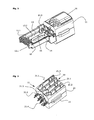
- Figure 2 exposes a view of the terminal block 11 and shows the shape of the shield plate 6 more clearly, which shields the plug inside on the entire length of the plug.
- FIG. 3 shows the contact receptacle 12 present in the interior of the plug housing, which is coupled to the terminal block 11 by means of a plug connection.
- the contacting holds eight plug contact elements 13, on which the Plug contacts 13.1 are formed.
- these contact elements with the plug or socket contacts are simply called “contact elements” 13, in contrast to the "terminal contact elements", which are described below and which have the insulation displacement terminals.
- the contact elements 13 lead from a terminal block facing the rear side with a fork contact 13.3 via a connecting portion 13.2 to the front of the plug with the plug contacts 13.1.
- the connecting sections 13.2 of some of the contact elements 13 are guided along the (in relation to the illustrated orientation) underside of a base area of the plug receptacle, while others extend along the upper side thereof.
- the shape and position of the contact elements with the exception of the plug contacts 13.1 depending on the embodiment chosen differently and, for example, be adapted so that the crosstalk between the contact elements corresponds to a specific specification.
- the position of the contact elements can be determined by their shape and the shape of the contact.
- an electrically conductive coupling element 14 is still drawn, which is isolated by an electrically insulating film 15 of the contact elements and controls the cross-talk (cross-talk ') between cable pairs controlled.
- the coupling element and its function will be described in more detail below.
- the plug housing 2 with inserted contact receptacle (not visible), the shield plate 6, the connection housing of the connection block 11 with wiring cover 16, the housing 5 and the union nut 8, each consisting of two housing parts 21, are each shown as separate components, for clarity, without contact elements.
- the terminal block 11 has, for example, a second wiring cover, which in the illustrated arrangement on the Bottom of the terminal block is detachably arranged.
- This second wiring cover is optional; ie it can also be a single wiring cover for the wiring on the top and on the bottom are used.
- wiring covers of the type drawn are known per se and will not be described further here.
- the plug is assembled from these items by before or after the circuit by means of wiring cover 16 of the terminal block 21 and the contact block - so the connector housing 2 with inserted contact receptacle 12 - are brought together.
- an electrical contact between the terminal contact elements and the contact elements is produced.
- the shield plate 6 is pushed from the front side - ie in the figure from the left side - over connector housing and terminal block.
- the outer casing and the union nut which have already been pushed over the cable before the wiring, are fastened from the rear side.
- the outer housing has elastic clamping elements 5.1, which narrow the passage when attaching the nut and clamp the contacted cable and thereby form a strain relief.
- FIG. 5 shows the terminal block without wiring cover.
- the terminal block 11 has a connection housing consisting of two housing parts 21. Between longitudinally extending intermediate webs 21.1 of the connection housing are Insertion slots 22 formed for the ladder. In each of these insertion slots 22 protrudes from the inside of the insulation displacement terminal 31.1 of a terminal contact element.
- the cutting clamps are offset from one another in the longitudinal direction and are at a 90 ° angle to the longitudinal direction. But there are also conceivable embodiments with not mutually offset insulation displacement terminals and / or aligned at a different angle to the longitudinal insulation displacement terminals.
- the terminal housing ribs 21.2 by means of which the conductors (including insulation) are clamped and which cause a Einzelleiterzugentlastung by preventing longitudinal movements and transverse movements of the inserted conductors. Also visible are laterally into the insertion slots 22 projecting retaining cam 21.3, as they are known from EP 0671780.
- the drawn retaining cams 21.3 are used for the positioning and temporary stabilization of the inserted conductors before the wiring (ie the pressing of the conductors between the insulation displacement terminals).
- second retaining cams could still be present, which are attached to the first holding cams and serve to fix the conductors after the wiring. In the illustrated embodiment, these second retaining cams are not needed, since the ribs 21.2 also stabilize against radial and displacements of the once wired conductors.
- the terminal contact elements each have a front end of the terminal housing projecting contact section 31.2, which have contact surfaces for contacting the contact elements.
- the contact parts 31.2 are pin-shaped and designed to interact with fork contact-like contact parts of the contact elements. Alternatively, they can act as solder pins for connection to a printed circuit.
- two positioning cams 21.4 of the housing parts protrude on the front side. These act when matching the terminal block with the contact block with appropriate not shown depressions in the contact block (eg. In the contact) together.
- connection housing has a transverse web 21.5 which extends transversely to an axial direction and lies in the radial direction outside a section 31.3, 31.4 of the connection contact elements 31.
- the transverse web 21.5 is arranged plug-in contact side in the axial direction in the terminal block, while the insertion slots 22 are open to the cable side.
- FIG. 6 shows the connection block according to FIG. 5 without the upper housing part.
- the terminal contact elements 31 have between the radially outwardly projecting insulation displacement terminals 31.1 and the contact parts 31.2 an axially (ie along the longitudinal direction) and extending between the housing parts connecting portion 31.3. Some of the terminal contact elements have in the region of the connecting portion a compensation surface 31.4, ie a flat, parallel to a (middle) plane extending section. Between a first group of terminal contact members 31 having a first insulation displacement opening direction (corresponding to the direction in which the blades protrude, upward in the figure) and a second group of connection contact elements 31 having a different cutting terminal opening direction (downward) an electrically insulating release film 32.
- both the first group of terminal contact elements 31 and the release film 32 are not drawn. It can be seen that compensation surfaces 31.4 of terminal contact elements 31 of the second group have approximately the same lateral position as corresponding compensation surfaces 31.4 of terminal contact elements 31 of the first group to have. This overlapping of compensation surfaces 31.4 on opposite sides of the release film 32 can also be seen in FIG. 8.
- connection housing parts 21 of the connection housing are shaped such that the connection contact elements 31 can be inserted from the inside, whereas insertion or removal from the outside or in the direction of the outside is not possible. This makes it possible that on the outside no special precautions (recesses, etc.) must be made for the insertion of the terminal contact elements.
- the insertion slots 22, the individual cable strain relief and the shape and position of the insulation displacement terminals can be designed to meet the needs.
- the two housing parts 21 of the terminal housing are joined together after the introduction of the terminal contact elements 31 and, if appropriate, the separation film 32 is connected permanently or reversibly by suitable means.
- suitable means As techniques for assembling the housing parts come snap connections, welding, gluing, etc. in question.
- connection housing In the production of a one-piece connection housing, however, the terminal contact elements and possibly also the separating film are fixed in an arrangement, as it is drawn, for example, in Figure 8.
- the fixation can be done by an injection molding tool, which is used for the production of the connection housing in an injection molding process.
- the release film 32 causes, in addition to an increase in the capacitive coupling between the compensation surfaces 31.4 of the terminal contact elements 31 (depending on Dielectric constant of the release film material) and an electrical separation and a precise definition of the distance between the terminal contact elements of the first and second group. With regard to the dielectric strength between the terminal contact elements, a necessary minimum spacing between the two groups of terminal contact elements is important.
- a release film can also be provided for at least one spacer, which is integrally formed on the housing parts 21 in the simplest case.
- the connecting portions of the terminal contact elements of the first and second group can run in the same plane but at different lateral positions.
- FIG. 9 The function of the compensation surfaces is illustrated in Figure 9 , where schematically four conductors 41, 42, 43, 44 of a data cable are shown. Because the conductors are not twisted in pairs in the wiring area but are guided in parallel, there is a capacitive coupling between adjacent conductors 41, 43 and 42, 44 and an inductive coupling between the conductor loops 41, 42 and 43, 44. in that two diagonally opposite conductors are capacitively coupled by means of the compensation surfaces 45, 46.
- the shape and relative position of the terminal contact elements 31 and contact elements 13 according to an embodiment of the invention is shown in FIG .
- the drawn position corresponds to the relative position of the terminal contact elements and contact elements when the terminal block and the contact block are coupled together.
- the contact parts 31.2 of the terminal contact elements 31 protrude into slots of fork contacts 13.3 of the contact elements, whereby an electrical contact is formed.
- the terminal contact elements of the first, upper group are coupled to contact elements, the connecting portions 13.2 on the upper side of Contact base (not drawn) run. Also visible is the characteristic circuitry that causes the first, second, third and sixth plug contacts 13.1 (from the left) to be connected to the terminal contact elements of the upper group and the fourth, fifth, seventh and eighth male contacts to the terminal contact elements of the lower group.
- Coupling elements 14, as drawn in FIG. 3, serve to compensate for crosstalk effects between pairs of conductors or contact elements extending parallel next to one another. As shown in FIG. 3, they can be present in the contact housing of a connector part designed according to the invention. But they can also be used in other, not inventive plug or socket housings, which are available for plug connections between data transmission cables of the "twisted pair" type, and which otherwise configured according to the prior art or according to a new, not yet known principle could be. They can also be used in strips or other parts of data transmission systems and in particular connector systems.
- the coupling element 14 can be seen in Figure 11b in a view. It has two coupling surfaces 14.1, 14.2, which is capacitively coupled by the dielectric to the contact elements to be coupled. In addition, two connecting parts 14.3 are present, which connect the two coupling surfaces together. In the illustrated arrangement, the connecting parts are present on the front side of the coupling element, ie they form the shorter sides of the almost rectangular coupling element.
- positioning openings 14.4 can still be seen, which interact with corresponding positioning cams (visible in FIG. 3) and, in particular, fix the lateral position.
- corresponding positioning cams visible in FIG. 3
- other positioning means are conceivable.
- the coupling element 114 in FIG. 12 is hat-shaped in a cross-section, so that it has a greater spacing from the contact element K2a located therebetween than from the contact elements K1b, K2b to be coupled.
- the arrangement according to Figure 13 provides that the intermediate contact element K2a is offset away from the coupling element 214 down.
- the coupling element may then be formed in accordance with FIG. 11b or 12, or it may also be simply plate-shaped without a recess as illustrated.
- the coupling element 314 of Figure 14 finally, works similar to that of Figure 11a, but has only one connecting part 314.3.
- the coupling element in a plug connection part, extend parallel to the connecting portion 13.2 of a contact element.
- the contact block can be designed according to a different plug standard than the RJ45 standard, for example according to the M12 standard which is widespread in industry.
- the bipartite terminal block - contact block is not necessary; the terminal housing can instead also form the plug housing.
- separate contact elements are not necessary, the (plug) contacts may be formed on the terminal contact elements.
- the drawn formations of the terminal contact elements and contact elements are to be understood as examples only.
Landscapes
- Details Of Connecting Devices For Male And Female Coupling (AREA)
- Coupling Device And Connection With Printed Circuit (AREA)
- Connections By Means Of Piercing Elements, Nuts, Or Screws (AREA)
- Multi-Conductor Connections (AREA)
- Manufacturing Of Electrical Connectors (AREA)
- Connections Arranged To Contact A Plurality Of Conductors (AREA)
Priority Applications (15)
| Application Number | Priority Date | Filing Date | Title |
|---|---|---|---|
| EP05405196A EP1693933A1 (de) | 2005-02-17 | 2005-02-17 | Steckverbinder für die Datenübertragung über elektrische Leiter |
| PL07021382T PL1883137T3 (pl) | 2005-02-17 | 2006-02-14 | Blok przyłączeniowy do zastosowania w łączniku wtykowym |
| AT07021382T ATE553519T1 (de) | 2005-02-17 | 2006-02-14 | Anschlussblock zur verwendung in einem steckverbindungsteil |
| DK07021382.2T DK1883137T3 (da) | 2005-02-17 | 2006-02-14 | Tilslutningsblok til anvendelse i en stikforbindelsesdel |
| EP07021382A EP1883137B1 (de) | 2005-02-17 | 2006-02-14 | Anschlussblock zur Verwendung in einem Steckverbindungsteil |
| US11/354,309 US7249979B2 (en) | 2005-02-17 | 2006-02-14 | Plug-and-socket connector for data transmission via electrical conductors |
| EP06405067.7A EP1693934B1 (de) | 2005-02-17 | 2006-02-14 | Steckverbinder für die Datenübertragung über elektrische Leiter |
| ES07021382T ES2380945T3 (es) | 2005-02-17 | 2006-02-14 | Bloque de empalme para uso en una pieza de conexión por enchufe |
| EP13182977.2A EP2672576B1 (de) | 2005-02-17 | 2006-02-14 | Steckverbinder für die Datenübertragung über elektrische Leiter |
| JP2006039217A JP2006228735A (ja) | 2005-02-17 | 2006-02-16 | プラグ−ソケット接続部品、プラグ−ソケット接続システム部品、接続ブロック、及びそれらの製造方法 |
| CN2006100090554A CN1835300B (zh) | 2005-02-17 | 2006-02-17 | 经由电导体进行数据传输的插头和插座连接器 |
| UAA200601698A UA88770C2 (ru) | 2005-02-17 | 2006-02-17 | Соединитель для разъемного соединения кабеля передачи данных, присоединительный блок для применения в соединителе и способ изготовления соединителя (варианты) |
| CN2010101491943A CN101901981B (zh) | 2005-02-17 | 2006-02-17 | 经由电导体进行数据传输的插头和插座连接器 |
| SG200601062A SG125219A1 (en) | 2005-02-17 | 2006-02-17 | A plug-and-socket connector for data transmission via electrical conductors |
| US11/828,662 US7540789B2 (en) | 2005-02-17 | 2007-07-26 | Plug-and-socket connector for data transmission via electrical conductors |
Applications Claiming Priority (1)
| Application Number | Priority Date | Filing Date | Title |
|---|---|---|---|
| EP05405196A EP1693933A1 (de) | 2005-02-17 | 2005-02-17 | Steckverbinder für die Datenübertragung über elektrische Leiter |
Publications (1)
| Publication Number | Publication Date |
|---|---|
| EP1693933A1 true EP1693933A1 (de) | 2006-08-23 |
Family
ID=34942923
Family Applications (4)
| Application Number | Title | Priority Date | Filing Date |
|---|---|---|---|
| EP05405196A Withdrawn EP1693933A1 (de) | 2005-02-17 | 2005-02-17 | Steckverbinder für die Datenübertragung über elektrische Leiter |
| EP07021382A Expired - Lifetime EP1883137B1 (de) | 2005-02-17 | 2006-02-14 | Anschlussblock zur Verwendung in einem Steckverbindungsteil |
| EP06405067.7A Expired - Lifetime EP1693934B1 (de) | 2005-02-17 | 2006-02-14 | Steckverbinder für die Datenübertragung über elektrische Leiter |
| EP13182977.2A Expired - Lifetime EP2672576B1 (de) | 2005-02-17 | 2006-02-14 | Steckverbinder für die Datenübertragung über elektrische Leiter |
Family Applications After (3)
| Application Number | Title | Priority Date | Filing Date |
|---|---|---|---|
| EP07021382A Expired - Lifetime EP1883137B1 (de) | 2005-02-17 | 2006-02-14 | Anschlussblock zur Verwendung in einem Steckverbindungsteil |
| EP06405067.7A Expired - Lifetime EP1693934B1 (de) | 2005-02-17 | 2006-02-14 | Steckverbinder für die Datenübertragung über elektrische Leiter |
| EP13182977.2A Expired - Lifetime EP2672576B1 (de) | 2005-02-17 | 2006-02-14 | Steckverbinder für die Datenübertragung über elektrische Leiter |
Country Status (10)
| Country | Link |
|---|---|
| US (2) | US7249979B2 (https=) |
| EP (4) | EP1693933A1 (https=) |
| JP (1) | JP2006228735A (https=) |
| CN (2) | CN1835300B (https=) |
| AT (1) | ATE553519T1 (https=) |
| DK (1) | DK1883137T3 (https=) |
| ES (1) | ES2380945T3 (https=) |
| PL (1) | PL1883137T3 (https=) |
| SG (1) | SG125219A1 (https=) |
| UA (1) | UA88770C2 (https=) |
Cited By (9)
| Publication number | Priority date | Publication date | Assignee | Title |
|---|---|---|---|---|
| WO2007084277A1 (en) * | 2006-01-23 | 2007-07-26 | Commscope, Inc. Of North Carolina | Communications connectors with parasitic and/or inductive coupling elements for reducing crosstalk and related methods |
| WO2008061780A3 (de) * | 2006-11-24 | 2008-07-17 | Phoenix Contact Gmbh & Co | Konfektionierbarer rundsteckverbinder für ethernet |
| EP2063497A1 (de) | 2007-11-26 | 2009-05-27 | Reichle & De-Massari AG | Steckverbinder |
| DE102008064535A1 (de) | 2008-12-19 | 2010-06-24 | Telegärtner Karl Gärtner GmbH | Elektrischer Verbindungsstecker |
| DE102009016875B3 (de) * | 2009-04-08 | 2010-11-04 | Harting Electric Gmbh & Co. Kg | Mehrpoliges Stecksystem und Verfahren zu seiner Herstellung |
| CN101632201B (zh) * | 2007-03-14 | 2013-05-01 | Adc有限公司 | 电连接器 |
| US9553392B2 (en) | 2014-03-28 | 2017-01-24 | Telegaertner Karl Gaertner Gmbh | Electrical plug connector having a plug-connection member and a cable outlet member |
| US9553402B2 (en) | 2014-03-28 | 2017-01-24 | Telegaertner Karl Gaertner Gmbh | Electrical plug connector with plug-in connection and cable outlet member |
| USRE49942E1 (en) * | 2011-10-05 | 2024-04-23 | Senko Advanced Components, Inc. | Latching connector with remote release |
Families Citing this family (68)
| Publication number | Priority date | Publication date | Assignee | Title |
|---|---|---|---|---|
| EP1693933A1 (de) * | 2005-02-17 | 2006-08-23 | Reichle & De-Massari AG | Steckverbinder für die Datenübertragung über elektrische Leiter |
| JP4380598B2 (ja) * | 2005-06-16 | 2009-12-09 | 株式会社日立製作所 | 受信装置及び受信方法 |
| JP4915585B2 (ja) * | 2006-09-21 | 2012-04-11 | パナソニック株式会社 | モジュラプラグ |
| DE102007008465B4 (de) | 2007-02-19 | 2008-10-16 | Tyco Electronics Amp Gmbh | Elektrisches Steckermodul insbesondere für eine RJ 45-Steckverbindung |
| AU2007201114B2 (en) * | 2007-03-14 | 2011-04-07 | Tyco Electronics Services Gmbh | Electrical Connector |
| AU2007201108B2 (en) * | 2007-03-14 | 2012-02-09 | Tyco Electronics Services Gmbh | Electrical Connector |
| AU2007201113B2 (en) * | 2007-03-14 | 2011-09-08 | Tyco Electronics Services Gmbh | Electrical Connector |
| AU2007201109B2 (en) * | 2007-03-14 | 2010-11-04 | Tyco Electronics Services Gmbh | Electrical Connector |
| AU2007201107B2 (en) * | 2007-03-14 | 2011-06-23 | Tyco Electronics Services Gmbh | Electrical Connector |
| AU2007201102B2 (en) * | 2007-03-14 | 2010-11-04 | Tyco Electronics Services Gmbh | Electrical Connector |
| AU2007201106B9 (en) * | 2007-03-14 | 2011-06-02 | Tyco Electronics Services Gmbh | Electrical Connector |
| US7857635B2 (en) * | 2007-09-12 | 2010-12-28 | Commscope, Inc. Of North Carolina | Board edge termination back-end connection assemblies and communications connectors including such assemblies |
| EP2210314A4 (en) * | 2007-11-02 | 2012-05-16 | Siemon Co | INSERT AND OUTDOOR PROTECTION DEVICE |
| DE102008057554B3 (de) * | 2008-11-15 | 2010-04-22 | Tyco Electronics Amp Gmbh | Elektrischer Steckverbinder mit Litzenführung |
| US7878841B2 (en) * | 2009-02-24 | 2011-02-01 | John Mezzalingua Associates, Inc. | Pull through modular jack and method of use thereof |
| JP5112383B2 (ja) * | 2009-05-28 | 2013-01-09 | ヒロセ電機株式会社 | モジュラープラグ |
| DE102010014295A1 (de) * | 2010-04-08 | 2011-10-13 | Phoenix Contact Gmbh & Co. Kg | Steckverbinder zur Aufnahme eines mehradrigen Kabels |
| DE202010010754U1 (de) | 2010-07-28 | 2010-10-21 | Harting Electronics Gmbh & Co. Kg | Steckverbinder mit Schneidklemmen und einem unverlierbaren Isolierkörper |
| US8241068B2 (en) | 2010-08-30 | 2012-08-14 | Tyco Electronics Corporation | Pluggable connector with differential pairs having an air core |
| US20120069516A1 (en) * | 2010-09-22 | 2012-03-22 | Panasonic Corporation | Electronic apparatus |
| CN102255171B (zh) * | 2011-05-09 | 2013-04-24 | 杭州嘉杭科技有限公司 | 插接免剥线式连接器 |
| CN102931521B (zh) * | 2011-08-10 | 2015-02-04 | 富士康(昆山)电脑接插件有限公司 | 线缆连接器组件 |
| DE102011090209B4 (de) * | 2011-12-30 | 2014-10-30 | Ims Connector Systems Gmbh | Elektrische Verbindungseinrichtung |
| US9509107B2 (en) | 2012-02-13 | 2016-11-29 | Commscope, Inc. Of North Carolina | Communication patch cord having a plug with contact blades connected to conductors of a cable |
| US8920199B2 (en) | 2012-02-13 | 2014-12-30 | Commscope, Inc. Of North Carolina | Patch cord having a plug with differential transmission lines |
| CN104247165B (zh) | 2012-02-13 | 2016-11-09 | 美国北卡罗来纳康普公司 | 具有低剖面表面安装的印刷电路板插头叶片的小形状因数模块化插头 |
| DE102012104622B4 (de) * | 2012-05-29 | 2019-04-04 | Phoenix Contact Gmbh & Co. Kg | RJ45-Stecker mit Führungseinrichtung für Litzen |
| US8814589B2 (en) * | 2012-06-04 | 2014-08-26 | Chant Sincere Co., Ltd. | Plug connector |
| KR101994984B1 (ko) | 2012-07-16 | 2019-07-01 | 콤스코프 인코포레이티드 오브 노스 캐롤라이나 | 균형 잡힌 핀 및 소켓 커넥터들 |
| US8714994B2 (en) | 2012-08-15 | 2014-05-06 | Tyco Electronics Corporation | Modular plug for power applications |
| US8979574B2 (en) | 2012-08-15 | 2015-03-17 | Tyco Electronics Corporation | Modular plug |
| DE102012110232B4 (de) * | 2012-10-26 | 2023-11-23 | Dr. Ing. H.C. F. Porsche Aktiengesellschaft | Verbindungsvorrichtung zur Stromübertragung im Kraftfahrzeugbereich |
| US8764476B1 (en) | 2012-12-06 | 2014-07-01 | Frank Ma | Transmission connector |
| US9379500B2 (en) | 2013-03-11 | 2016-06-28 | Panduit Corp. | Front sled assemblies for communication jacks and communication jacks having front sled assemblies |
| US8858267B2 (en) | 2013-03-14 | 2014-10-14 | Commscope, Inc. Of North Carolina | Communications plugs and patch cords with mode conversion control circuitry |
| US10326229B2 (en) | 2013-03-15 | 2019-06-18 | Knxid, Llc | Termination identification device and system |
| DE102013209327B4 (de) | 2013-05-21 | 2015-02-12 | Tyco Electronics Amp Gmbh | Elektrischer Steckverbinder |
| KR20150024088A (ko) * | 2013-08-26 | 2015-03-06 | 주식회사 케이엠더블유 | 엘이디 가로등 |
| DE102013224042A1 (de) * | 2013-11-25 | 2015-05-28 | Tyco Electronics Amp Gmbh | Anordnung für einen elektrischen Stecker |
| DE102014100544A1 (de) * | 2014-01-20 | 2015-07-23 | Reichle + De-Massari Ag | Steckverbindervorrichtung |
| TWM481498U (zh) * | 2014-01-29 | 2014-07-01 | Amphenol Ltw Technology Co Ltd | 電連接器(二) |
| CN104917854B (zh) * | 2014-03-12 | 2017-08-25 | 纬创资通股份有限公司 | 信号传输装置 |
| CN104409925B (zh) * | 2014-11-06 | 2017-04-12 | 北京海航通联光电技术开发有限公司 | 一种小型化圆形网络电连接器 |
| GB2547958B (en) | 2016-03-04 | 2019-12-18 | Commscope Technologies Llc | Two-wire plug and receptacle |
| JP6614051B2 (ja) * | 2016-07-12 | 2019-12-04 | 株式会社オートネットワーク技術研究所 | 電気接続アセンブリの製造方法 |
| TWM536801U (zh) | 2016-10-21 | 2017-02-11 | Jyh Eng Technology Co Ltd | 網路插頭結構 |
| US20180323550A1 (en) * | 2017-03-31 | 2018-11-08 | Sentinel Connector Systems, Inc. | Single-pair ethernet plug |
| US11652322B2 (en) | 2017-04-24 | 2023-05-16 | Commscope Technologies Llc | Connectors for a single twisted pair of conductors |
| WO2018227057A1 (en) | 2017-06-08 | 2018-12-13 | Commscope Technologies Llc | Connectors for a single twisted pair of conductors |
| WO2019147774A1 (en) | 2018-01-26 | 2019-08-01 | Commscope Technologies Llc | Connectors for a single twisted pair of conductors |
| CN108400507A (zh) * | 2018-02-11 | 2018-08-14 | 富延升电子(福建)有限公司 | 一种以太网插头连接器 |
| AU2019223204B2 (en) | 2018-02-26 | 2024-06-06 | Commscope Technologies Llc | Connectors and contacts for a single twisted pair of conductors |
| DE102018214203A1 (de) * | 2018-08-22 | 2020-02-27 | Te Connectivity Germany Gmbh | Kontaktanordnung |
| EP3847720A1 (en) * | 2018-09-05 | 2021-07-14 | Panduit Corp. | Field terminable single pair ethernet connector |
| DE102019104881B4 (de) * | 2019-02-26 | 2020-12-10 | Pilz Gmbh & Co. Kg | Speichervorrichtung zur mobilen Bereitstellung von Daten an einer technischen Einrichtung |
| US11894637B2 (en) * | 2019-03-15 | 2024-02-06 | Commscope Technologies Llc | Connectors and contacts for a single twisted pair of conductors |
| USD962169S1 (en) * | 2019-03-29 | 2022-08-30 | Jyh Eng Technology Co., Ltd. | Network cable plug |
| EP3758163A1 (en) | 2019-06-24 | 2020-12-30 | TE Connectivity Nederland B.V. | Plug insert for a connector assembly and connector assembly |
| US11228132B2 (en) * | 2019-07-01 | 2022-01-18 | Panduit Corp. | Single pair ethernet field terminable connector |
| US12316055B2 (en) | 2019-09-30 | 2025-05-27 | Commscope Technologies Llc | Couplers for single pair connectors |
| WO2021067268A1 (en) | 2019-09-30 | 2021-04-08 | Commscope Technologies Llc | High density coupling panel |
| US12322914B2 (en) | 2019-11-19 | 2025-06-03 | Panduit Corp. | Field terminable single pair ethernet connector with angled contacts |
| US11811181B2 (en) * | 2019-11-19 | 2023-11-07 | Panduit Corp. | Field terminable single pair ethernet connector with angled contacts |
| CN114759382A (zh) * | 2021-01-08 | 2022-07-15 | 康普技术有限责任公司 | 通信线缆连接器 |
| US12199372B2 (en) | 2021-02-26 | 2025-01-14 | Commscope Technologies Llc | Couplers for single pair connectors |
| WO2024049650A1 (en) * | 2022-08-31 | 2024-03-07 | Panduit Corp. | Field terminable single pair ethernet connector with angled contacts |
| CN116231350A (zh) * | 2022-12-27 | 2023-06-06 | 富晋精密工业(晋城)有限公司 | 适配器、连接器以及光电同传连接组件 |
| USD1063863S1 (en) * | 2024-11-09 | 2025-02-25 | Shenzhen Fangzhong Technology Limited | Electrical connecter |
Citations (6)
| Publication number | Priority date | Publication date | Assignee | Title |
|---|---|---|---|---|
| EP0590667A1 (en) * | 1992-10-01 | 1994-04-06 | The Whitaker Corporation | High-density cable connector |
| US5403200A (en) * | 1994-05-04 | 1995-04-04 | Chen; Michael | Electric connecting block |
| WO1997044862A1 (en) * | 1996-05-23 | 1997-11-27 | The Siemon Company | Reduced crosstalk modular outlet |
| US6102730A (en) * | 1995-09-01 | 2000-08-15 | Cekan/Cdt A/S | Connector element for telecommunications |
| US6338655B1 (en) * | 1999-03-16 | 2002-01-15 | Infra + | Low-voltage connector provided with an adapter, and an adapter for such a connector |
| US6786775B1 (en) * | 2003-06-10 | 2004-09-07 | Molex Incorporated | Modular jack assembly |
Family Cites Families (26)
| Publication number | Priority date | Publication date | Assignee | Title |
|---|---|---|---|---|
| GB2271678B (en) * | 1993-12-03 | 1994-10-12 | Itt Ind Ltd | Electrical connector |
| CH687841A5 (de) | 1994-03-10 | 1997-02-28 | Reichle & De Massari Fa | Mehrfach-Kontaktstifthalter fuer Schwachstrom-Anlagen. |
| GB9511777D0 (en) * | 1995-06-09 | 1995-08-02 | Astralux Dynamics Ltd | Connector apparatus |
| JPH09167645A (ja) * | 1995-12-15 | 1997-06-24 | Matsushita Electric Works Ltd | モジュラジャック |
| JPH10134858A (ja) * | 1996-11-01 | 1998-05-22 | Sumitomo Wiring Syst Ltd | コネクタ |
| US5989071A (en) | 1997-09-03 | 1999-11-23 | Lucent Technologies Inc. | Low crosstalk assembly structure for use in a communication plug |
| US5951330A (en) * | 1997-09-03 | 1999-09-14 | Lucent Technologies Inc. | Alignment apparatus for use in the jack interface housing of a communication plug |
| DE29804836U1 (de) | 1998-03-18 | 1998-07-23 | Albert Ackermann GmbH & Co. KG, 51643 Gummersbach | Steckverbinder für ein geschirmtes Kabel |
| US6398591B1 (en) | 1998-05-12 | 2002-06-04 | Stewart Connector Systems, Inc. | Modular jack for tubular enclosures |
| DE19822630C1 (de) * | 1998-05-20 | 2000-09-07 | Krone Gmbh | Anordnung von Kontaktpaaren zur Kompensation des Nahnebensprechens für eine elektrische Steckverbindung |
| CH695034A5 (de) | 1998-09-30 | 2005-11-15 | Reichle & De Massari Fa | Steckverbindungsteil einer Steckverbindung fuer hochfrequente Datenuebertragung ueber elektrische Leiter. |
| GB2343558B (en) * | 1998-11-04 | 2002-10-30 | Itt Mfg Enterprises Inc | Electrical connector |
| US6139368A (en) * | 1998-12-21 | 2000-10-31 | Thomas & Betts International, Inc. | Filtered modular connector |
| JP2001210434A (ja) * | 2000-01-31 | 2001-08-03 | Matsushita Electric Works Ltd | モジュラプラグ |
| EP1128494B1 (de) | 2000-02-24 | 2006-08-02 | Reichle & De-Massari AG | Adapter und Stecker für die Kommunikations- und Steuerungstechnik |
| DE10055148C2 (de) | 2000-11-07 | 2003-05-22 | Phoenix Contact Gmbh & Co | Kabelanschluß- oder -verbindungseinrichtung |
| US6413121B1 (en) * | 2001-05-22 | 2002-07-02 | Hon Hai Precision Ind. Co., Ltd. | RJ modular connector having printed circuit board having conductive trace to balance electrical couplings between terminals |
| JP4081003B2 (ja) | 2001-07-31 | 2008-04-23 | ライヒレ・ウント・デ−マサリ・アクチエンゲゼルシヤフト | 差込式コネクタのための保護装置 |
| CN2575867Y (zh) * | 2002-09-17 | 2003-09-24 | 莫列斯公司 | 线缆连接器 |
| DE10258725B4 (de) | 2002-12-05 | 2005-08-25 | Novar Gmbh | Steckverbinder für informationstechnische Anschlüsse |
| US6890210B2 (en) * | 2003-03-21 | 2005-05-10 | Hon Hai Precision Ind. Co., Ltd. | Cable connector assembly with IDC contacts |
| US6752647B1 (en) | 2003-05-02 | 2004-06-22 | Jyh Eng Industrial Co., Ltd. | Rotary insulation displacement connector |
| US7179115B2 (en) * | 2004-04-26 | 2007-02-20 | Commscope Solutions Properties, Llc | Alien next compensation for adjacently placed connectors |
| US7186149B2 (en) * | 2004-12-06 | 2007-03-06 | Commscope Solutions Properties, Llc | Communications connector for imparting enhanced crosstalk compensation between conductors |
| US7175476B2 (en) * | 2005-01-11 | 2007-02-13 | Daeun Electronics Co., Ltd. | Crosstalk canceling pattern for high-speed communications and modular jack having the same |
| EP1693933A1 (de) * | 2005-02-17 | 2006-08-23 | Reichle & De-Massari AG | Steckverbinder für die Datenübertragung über elektrische Leiter |
-
2005
- 2005-02-17 EP EP05405196A patent/EP1693933A1/de not_active Withdrawn
-
2006
- 2006-02-14 DK DK07021382.2T patent/DK1883137T3/da active
- 2006-02-14 ES ES07021382T patent/ES2380945T3/es not_active Expired - Lifetime
- 2006-02-14 PL PL07021382T patent/PL1883137T3/pl unknown
- 2006-02-14 US US11/354,309 patent/US7249979B2/en not_active Expired - Fee Related
- 2006-02-14 EP EP07021382A patent/EP1883137B1/de not_active Expired - Lifetime
- 2006-02-14 EP EP06405067.7A patent/EP1693934B1/de not_active Expired - Lifetime
- 2006-02-14 EP EP13182977.2A patent/EP2672576B1/de not_active Expired - Lifetime
- 2006-02-14 AT AT07021382T patent/ATE553519T1/de active
- 2006-02-16 JP JP2006039217A patent/JP2006228735A/ja active Pending
- 2006-02-17 CN CN2006100090554A patent/CN1835300B/zh not_active Expired - Fee Related
- 2006-02-17 CN CN2010101491943A patent/CN101901981B/zh not_active Expired - Fee Related
- 2006-02-17 UA UAA200601698A patent/UA88770C2/ru unknown
- 2006-02-17 SG SG200601062A patent/SG125219A1/en unknown
-
2007
- 2007-07-26 US US11/828,662 patent/US7540789B2/en not_active Expired - Lifetime
Patent Citations (6)
| Publication number | Priority date | Publication date | Assignee | Title |
|---|---|---|---|---|
| EP0590667A1 (en) * | 1992-10-01 | 1994-04-06 | The Whitaker Corporation | High-density cable connector |
| US5403200A (en) * | 1994-05-04 | 1995-04-04 | Chen; Michael | Electric connecting block |
| US6102730A (en) * | 1995-09-01 | 2000-08-15 | Cekan/Cdt A/S | Connector element for telecommunications |
| WO1997044862A1 (en) * | 1996-05-23 | 1997-11-27 | The Siemon Company | Reduced crosstalk modular outlet |
| US6338655B1 (en) * | 1999-03-16 | 2002-01-15 | Infra + | Low-voltage connector provided with an adapter, and an adapter for such a connector |
| US6786775B1 (en) * | 2003-06-10 | 2004-09-07 | Molex Incorporated | Modular jack assembly |
Cited By (13)
| Publication number | Priority date | Publication date | Assignee | Title |
|---|---|---|---|---|
| US7381097B2 (en) | 2006-01-23 | 2008-06-03 | Commscope, Inc. Of North Carolina | Communications connectors with parasitic and/or inductive coupling elements for reducing crosstalk and related methods |
| WO2007084277A1 (en) * | 2006-01-23 | 2007-07-26 | Commscope, Inc. Of North Carolina | Communications connectors with parasitic and/or inductive coupling elements for reducing crosstalk and related methods |
| US7938650B2 (en) | 2006-11-24 | 2011-05-10 | Phoenix Contact Gmbh & Co. Kg | Manufactured round plug connector for Ethernet |
| WO2008061780A3 (de) * | 2006-11-24 | 2008-07-17 | Phoenix Contact Gmbh & Co | Konfektionierbarer rundsteckverbinder für ethernet |
| CN101632201B (zh) * | 2007-03-14 | 2013-05-01 | Adc有限公司 | 电连接器 |
| EP2063497A1 (de) | 2007-11-26 | 2009-05-27 | Reichle & De-Massari AG | Steckverbinder |
| WO2010069625A1 (de) * | 2008-12-19 | 2010-06-24 | Telegärtner Karl Gärtner GmbH | Elektrischer verbindungsstecker |
| US8298922B2 (en) | 2008-12-19 | 2012-10-30 | Telegaertner Karl Gaertner Gmbh | Electrical plug connector |
| DE102008064535A1 (de) | 2008-12-19 | 2010-06-24 | Telegärtner Karl Gärtner GmbH | Elektrischer Verbindungsstecker |
| DE102009016875B3 (de) * | 2009-04-08 | 2010-11-04 | Harting Electric Gmbh & Co. Kg | Mehrpoliges Stecksystem und Verfahren zu seiner Herstellung |
| USRE49942E1 (en) * | 2011-10-05 | 2024-04-23 | Senko Advanced Components, Inc. | Latching connector with remote release |
| US9553392B2 (en) | 2014-03-28 | 2017-01-24 | Telegaertner Karl Gaertner Gmbh | Electrical plug connector having a plug-connection member and a cable outlet member |
| US9553402B2 (en) | 2014-03-28 | 2017-01-24 | Telegaertner Karl Gaertner Gmbh | Electrical plug connector with plug-in connection and cable outlet member |
Also Published As
| Publication number | Publication date |
|---|---|
| EP1693934A1 (de) | 2006-08-23 |
| SG125219A1 (en) | 2006-09-29 |
| US7249979B2 (en) | 2007-07-31 |
| JP2006228735A (ja) | 2006-08-31 |
| EP1883137A3 (de) | 2008-03-05 |
| UA88770C2 (ru) | 2009-11-25 |
| CN101901981A (zh) | 2010-12-01 |
| EP2672576B1 (de) | 2016-05-18 |
| CN1835300B (zh) | 2010-06-09 |
| DK1883137T3 (da) | 2012-05-21 |
| EP1883137A2 (de) | 2008-01-30 |
| ATE553519T1 (de) | 2012-04-15 |
| PL1883137T3 (pl) | 2012-09-28 |
| ES2380945T3 (es) | 2012-05-21 |
| CN101901981B (zh) | 2012-04-18 |
| EP2672576A2 (de) | 2013-12-11 |
| CN1835300A (zh) | 2006-09-20 |
| US20060183359A1 (en) | 2006-08-17 |
| EP1883137B1 (de) | 2012-04-11 |
| US7540789B2 (en) | 2009-06-02 |
| EP2672576A3 (de) | 2014-01-15 |
| EP1693934B1 (de) | 2020-08-19 |
| US20080057793A1 (en) | 2008-03-06 |
Similar Documents
| Publication | Publication Date | Title |
|---|---|---|
| EP2672576B1 (de) | Steckverbinder für die Datenübertragung über elektrische Leiter | |
| EP3031103B1 (de) | System aus mehreren elektrischen steckverbindermodulen und einem elektrisch leitfähigen halterahmen | |
| DE69829120T2 (de) | Anschlussblock für Federdrähte für Kommunikationsverbinder | |
| DE69838894T2 (de) | Zugentlastungsvorrichtung für Nachrichtenstecker | |
| EP0595234B1 (de) | Kabelstecker für vieladrige Kabel | |
| DE69836510T2 (de) | Nachrichtenstecker | |
| DE69938109T2 (de) | Elektrisches Filter-Verbindersystem | |
| DE69838896T2 (de) | Kontaktzungenträger für Nachrichtenstecker | |
| DE2301398B2 (de) | Anschlußvorrichtung für elektrische Leitungsadern | |
| EP3701606B1 (de) | Leitungshaltersystem, stromschienenelement, verfahren zur herstellung eines stromschienenelements und verfahren zur herstellung eines stromschienensystems | |
| DE102017120095A1 (de) | Steckverbinder mit Kurzschlussbrücken | |
| DE3843664A1 (de) | Anschlussblock | |
| DE2536135A1 (de) | Elektrische verbindungsanordnung | |
| DE3685814T2 (de) | Zusammenbau eines elektrischen verbinders und verfahren zur ausfuehrung desselben. | |
| DE69931591T2 (de) | Leiterplatte für Modularstecker | |
| DE112022005990T5 (de) | Einpaariges Ethernetverbindungssystem | |
| DE69618615T2 (de) | Elektrischer verbinder mit verschiedenen leiteranordnungen an den gegenueberliegenden enden | |
| EP0660442B1 (de) | Leiterplattenklemme | |
| DE102008045839B4 (de) | Anschlussdose | |
| WO2002095877A1 (de) | Steckverbinder, insbesondere zum kontaktieren einer unterschiedlich ausgebildete kontaktstellen aufweisenden elektrischen leitung, und anordnung aus steckverbinder und elektrischer leitung | |
| DE2829721C3 (de) | Mosaikbaustein für Schalt- und Meldewarten | |
| EP0809332A1 (de) | Steckverbinder | |
| DE4411731B4 (de) | Aufputz-Steckdose | |
| DE69205985T2 (de) | Elektrische Verbinderanordnung mit Isolierungsverdrängung. | |
| EP0296095B1 (de) | Anschlusseinheit für Kabelpaare der Fernmeldetechnik |
Legal Events
| Date | Code | Title | Description |
|---|---|---|---|
| PUAI | Public reference made under article 153(3) epc to a published international application that has entered the european phase |
Free format text: ORIGINAL CODE: 0009012 |
|
| AK | Designated contracting states |
Kind code of ref document: A1 Designated state(s): AT BE BG CH CY CZ DE DK EE ES FI FR GB GR HU IE IS IT LI LT LU MC NL PL PT RO SE SI SK TR |
|
| AX | Request for extension of the european patent |
Extension state: AL BA HR LV MK YU |
|
| AKX | Designation fees paid | ||
| REG | Reference to a national code |
Ref country code: DE Ref legal event code: 8566 |
|
| STAA | Information on the status of an ep patent application or granted ep patent |
Free format text: STATUS: THE APPLICATION IS DEEMED TO BE WITHDRAWN |
|
| 18D | Application deemed to be withdrawn |
Effective date: 20070224 |